murchison decommissioning comparative assessment report · comparative assessment report - 2 -...
TRANSCRIPT
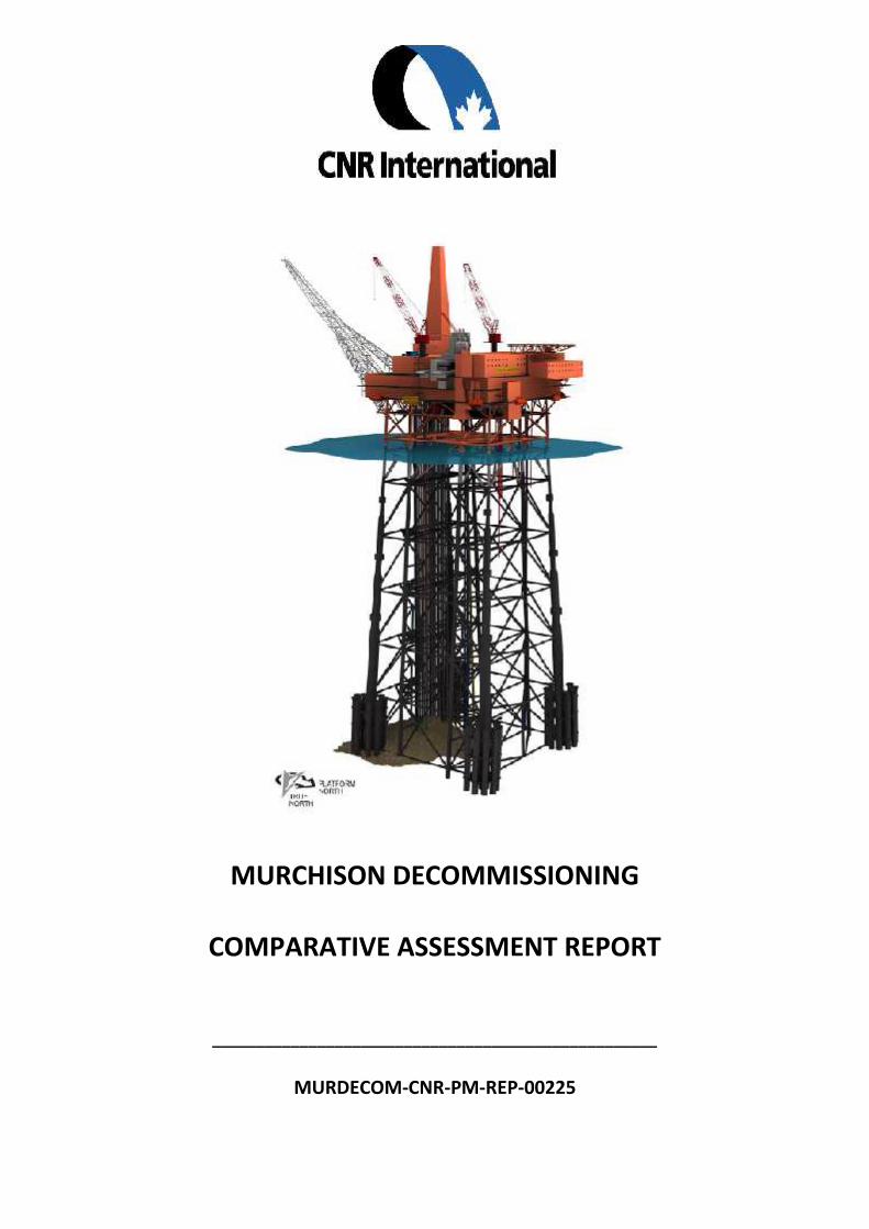
MURCHISON DECOMMISSIONING
COMPARATIVE ASSESSMENT REPORT
___________________________________________________
MURDECOM-CNR-PM-REP-00225
MurchisonComparative Assessment
Report
- 2 - 28/11/2013
Date Issue Description Rev By Chk App
21.09.12 Preliminary draft for Information1 MC CB
26.09.12 Draft for comment 2 MC SG/SE/RA/LG/GP RA
19.10.12 Draft for IRC Review 3 MC CB
23.10.12 Issued as Pre-read for StakeholderReview Nov 2012
4 MC CB RA
30.11.12 Issued in support of Murchison PreviewCopy - Decommissioning Programme
5 MC RA
01.05.13 Issued in Support of MurchisonConsultation Draft Programme
6 MC CB RA
Document Security:(Select one only)
Confidential: Standard: Open:
Restricted to ILT; CNRIManagement Team;Project Team
Restricted to ILT; CNRIManagement Team;Project Team; ProjectTechnical Authorities
Open to all

MurchisonComparative Assessment
Report
- 3 - 28/11/2013
Table of Contents
Preface............................................................................................................................................ 9
1. Executive Summary ................................................................................................................. 14
2 Project Description .................................................................................................................... 23
2.1 Murchison Field Development ........................................................................................... 23
2.2 Murchison Field Layout ...................................................................................................... 24
2.3 Description of the Murchison Platform ............................................................................. 25
2.3.1 The Murchison Jacket.................................................................................................. 25
2.3.2 The Murchison Platform Topsides .............................................................................. 26
2.4 Fabrication and Installation of the Murchison Platform.................................................... 29
2.4.1 Fabrication of the Murchison Jacket ........................................................................... 29
2.4.2 Fabrication of the Murchison Topside Modules ......................................................... 31
2.4.3 Murchison Jacket Condition Survey ............................................................................ 33
2.4.4 Murchison Topside Condition Survey ......................................................................... 33
2.5 Murchison Pipeline Infrastructure ..................................................................................... 34
2.5.1 Murchison Pipeline Bundles............................................................................................ 35
2.5.2 Murchison Pipeline PL115 ........................................................................................... 36
2.5.3 Murchison Gas Import Riser to the NLGP - PL165 ...................................................... 38
2.6 Murchison Operations and Drilling .................................................................................... 39
2.6.1 Murchison Subsea Wells ............................................................................................. 39
2.6.2 Murchison Platform Wells and Characteristics of the Drill Cuttings Pile.................... 41
2.7 The Murchison Environmental Setting .............................................................................. 44
2.7.1 Bathymetry.................................................................................................................. 45
2.7.3 Extreme Metocean Criteria ......................................................................................... 46
2.8 Marine Activity around Murchison .................................................................................... 47
2.8.1 Adjacent Oil and Gas Infrastructure............................................................................ 47
2.8.2 Shipping ....................................................................................................................... 47
2.8.3 Defence ....................................................................................................................... 47
2.8.4 Telecommunications and Cables................................................................................. 47
2.8.5 Wrecks ......................................................................................................................... 47
2.8.6 Fishing.......................................................................................................................... 47
2.8.7 Annex 1 Habitats ......................................................................................................... 48
3 Murchison Decommissioning Options ...................................................................................... 49
3.1 Post CoP Alternate Use Options......................................................................................... 49
3.1.1 Relocation and Reuse of Murchison Platform ............................................................ 49

MurchisonComparative Assessment
Report
- 4 - 28/11/2013
3.1.2 Potential Alternate Reuse for Wind Energy ................................................................ 50
3.1.3 Potential for Wave & Tidal Energy .............................................................................. 51
3.1.4 Potential for Carbon Capture ...................................................................................... 52
3.1.5 Alternate Non Energy Uses for the Murchison Platform ............................................ 54
3.1.6 Conclusion from Alternate Use Appraisal ................................................................... 54
3.2 Platform Removal Technology – Available Options ........................................................... 54
3.2.1 Murchison Platform Vessel Selection ......................................................................... 54
3.2.2 Pipeline Vessel Selection ............................................................................................. 55
3.3 Murchison Decommissioning Options ............................................................................... 57
3.3.1 Well Plug and Abandon (P&A) Procedures ................................................................. 57
3.3.2 Platform Topsides Decommissioning Procedures....................................................... 58
3.3.3 Platform Jacket Decommissioning Options ................................................................ 60
3.3.4 Murchison Drill Cuttings Management Options ......................................................... 67
3.3.5 Jacket and Drill Cuttings Option Interdependence ..................................................... 69
3.3.6 Export Pipeline PL115 Decommissioning Options ...................................................... 70
3.3.7 Pipeline Bundles PL123, PL124, PL125 Decommissioning Options ............................ 73
3.3.8 Seabed Debris Options ................................................................................................ 74
3.3.9 Summary of Options Carried Forward to the Comparative Assessment .................... 74
4 The Comparative Assessment Process ...................................................................................... 76
4.1 Purpose of the Comparative Assessment .......................................................................... 76
4.2 CNRI CA Method Statement............................................................................................... 76
4.3 CA Criteria and Scoring....................................................................................................... 76
4.4 CA Process .......................................................................................................................... 80
5 – The Comparative Assessment Workshop............................................................................... 81
5.1 Introduction........................................................................................................................ 81
5.2 Murchison Jacket – Results of Comparative Assessment .................................................. 82
5.2.1 Jacket Options scoring for sub criteria ........................................................................ 82
5.2.2 Jacket Safety Comparative Assessment ...................................................................... 83
5.2.3 Jacket Environmental Comparative Assessment ........................................................ 84
5.2.4 Jacket Technical Comparative Assessment ................................................................. 85
5.2.5 Jacket Societal Comparative Assessment ................................................................... 87
5.2.6 Jacket Economic Comparative Assessment ................................................................ 87
5.2.7 Stakeholder Concerns on Jacket Removal Options..................................................... 87
5.2.8 Recommended option for Decommissioning the Murchison Jacket .......................... 87
5.2.9 Jacket Sensitivity Analysis of Options’ Performance .................................................. 88
5.3 Murchison drill cuttings pile – Results of Comparative Assessment ................................. 88
5.3.1 Drill Cuttings Pile sub criteria scores........................................................................... 89
MurchisonComparative Assessment
Report
- 5 - 28/11/2013
5.3.2 Drill Cuttings Safety Comparative Assessment ........................................................... 89
5.3.3 Drill Cuttings Environmental Comparative Assessment ............................................. 89
5.3.4 Drill Cuttings Technical Comparative Assessment ...................................................... 90
5.3.5 Drill Cuttings Societal Comparative Assessment......................................................... 91
5.3.6 Drill Cuttings Cost Comparative Assessment .............................................................. 91
5.3.7 Stakeholder Concerns on Drill Cutting management Options .................................... 91
5.3.8 Recommended Option for Decommissioning the Murchison Drill Cuttings Pile........ 92
5.3.9 Sensitivity analysis of options’ performance .............................................................. 92
5.4 Combined Jacket and Drill Cuttings Pile............................................................................. 92
5.5 Murchison Pipeline PL115 Results of Comparative Assessment ....................................... 93
5.5.1 PL115 sub criteria scores............................................................................................. 93
5.5.2 PL115 Safety Comparative Assessment ...................................................................... 94
5.5.3 PL115 Environmental Comparative Assessment ........................................................ 95
5.5.4 PL115 Technical Comparative Assessment ................................................................. 96
5.5.5 PL115 Societal Comparative Assessment.................................................................... 96
5.5.6 PL115 Cost Comparative Assessment ......................................................................... 96
5.5.7 PL115 Stakeholder Concerns....................................................................................... 97
5.5.8 Recommended Option for Decommissioning the Murchison Pipeline PL115............ 97
5.5.9 PL115 Sensitivity analysis of options’ performance.................................................... 97
6 Independent Review Consultants – Verification Certificate ..................................................... 99
7 Reference Documents ............................................................................................................. 101
7.1Regulations and Procedures ............................................................................................. 101
7.2 Surveys ............................................................................................................................. 101
7.3 Removal Studies ............................................................................................................... 102
7.4 Drill Cuttings ..................................................................................................................... 103
7.5 Environment ..................................................................................................................... 103
7.6 Pipeline ............................................................................................................................. 104
7.7 Safety................................................................................................................................ 105
7.8 Comparative Assessment & Stakeholder Workshops ...................................................... 106

MurchisonComparative Assessment
Report
- 6 - 28/11/2013
List of Tables
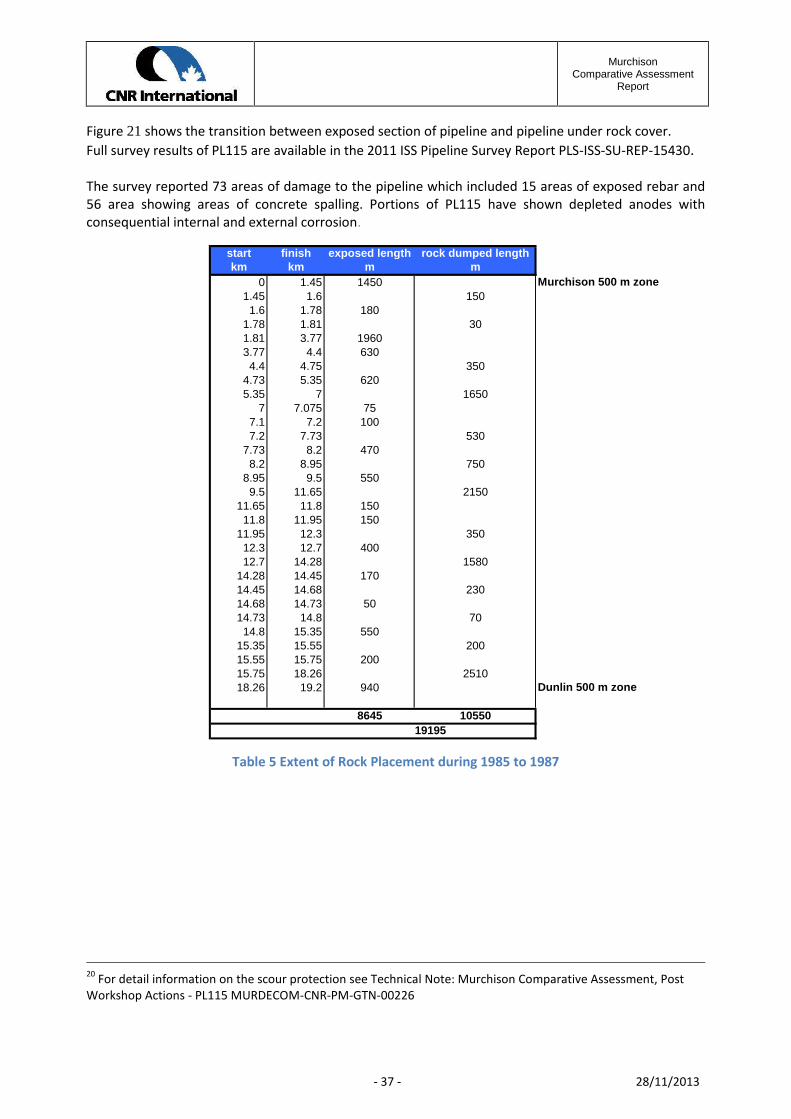
Table 1 OSPAR 2006/5 Thresholds & Murchison Values........................................................................... 20Table 2 Jacket Summary Weights.............................................................................................................. 26Table 3 Murchison Topside Module - Removal Weights........................................................................... 28Table 4 Pipeline Bundle Summary Details................................................................................................. 35Table 5 Extent of Rock Placement during 1985 to 1987 ........................................................................... 37Table 6 Assumed History of Murchison Drilling Muds .............................................................................. 42Table 7 Average Values across Boreholes ................................................................................................. 45Table 8 Extreme Metocean Data............................................................................................................... 46Table 9 Heavy Lift Vessel Capability .......................................................................................................... 54Table 10 Pipeline Vessel Capacities........................................................................................................... 55Table 11 Subsea Cutting Equipment Capability......................................................................................... 56Table 12 Jacket Drill Cutting Options Interdependence............................................................................ 69Table 13 The Criteria and sub criteria used in the CNRI Comparative Assessments................................. 78Table 14 Jacket Options- Sub-criteria Score.............................................................................................. 83Table 15: Ranked Decommissioning Options for the Murchison Jacket ................................................... 88Table 16 Drill Cuttings Pile - Sub-criteria Scores ....................................................................................... 89Table 17: Ranked Decommissioning Options for the Murchison Drill Cuttings Pile ................................. 92Table 18: Combined Ranked Decommissioning Options for the Murchison Jacket and Drill Cuttings Pile
.......................................................................................................................................................... 93Table 19 PL115 Decommissioning Options - Sub-criteria Scoring............................................................. 94Table 20: Ranked decommissioning options for the pipeline PL115 ........................................................ 97

MurchisonComparative Assessment
Report
- 7 - 28/11/2013
List of Figures
Figure 1: Murchison Field Map................................................................................................................. 23Figure 2: Murchison Field Layout ............................................................................................................ 24Figure 3: Murchison Platform Components .............................................................................................. 25Figure 4: Murchison Topside Configuration ............................................................................................. 27Figure 5: Layout of Jacket in Yard............................................................................................................. 29Figure 6: Roll up of Jacket Outer Frame .................................................................................................... 29Figure 7: Installation of the Bottles Legs ................................................................................................... 29Figure 8: The Bottle Leg Assembly............................................................................................................. 30Figure 9: Jacket Prepared for Loadout ...................................................................................................... 30Figure 10: Loadout of the Murchison Jacket ............................................................................................. 30Figure 11: Jacket Being Towed to Site ....................................................................................................... 30Figure 12: Jacket Launch ........................................................................................................................... 31Figure 13: Jacket Piling............................................................................................................................. 31Figure 14: Installation of Topside Modules .............................................................................................. 32Figure 15: First Topside Module Installed ................................................................................................ 32Figure 16: Second Level of Modules Being Installed ................................................................................ 32Figure 17: Hook Up and Commissioning of Modules ................................................................................ 32Figure 18: Murchison Subsea Infrastructure............................................................................................. 34Figure 19: Tow Out of Flowline Bundle ..................................................................................................... 35Figure 20: Laying the 16" OEL to Dunlin .................................................................................................... 36Figure 21: Transition exposed pipeline and rock profile ........................................................................... 38Figure 22: PL115 Schematic...................................................................................................................... 38Figure 23: PL165 Schematic....................................................................................................................... 39Figure 24: 211/19-2 Subsea Installation................................................................................................... 40Figure 25: Murchison Well Slot Diagram................................................................................................... 41Figure 26: Drilling Production Wells on Murchison................................................................................... 41Figure 27: MBES Survey Data of the Murchison Drill Cuttings Pile ........................................................... 43Figure 28: Murchison Environmental Setting............................................................................................ 44Figure 29: Jacket Key Plan ......................................................................................................................... 44Figure 30: Bathymetry Map of the Murchison Area ................................................................................. 45Figure 31: Concept for a 10MW Vertical Axis Turbine .............................................................................. 50Figure 32: Seagen Drive............................................................................................................................. 51Figure 33: Pelamis Device Prototype......................................................................................................... 51Figure 34: CCS Schematic .......................................................................................................................... 53Figure 35: Trenching Equipment V Soil Type............................................................................................. 56Figure 36: SSCV Lifts off Topside Module.................................................................................................. 59Figure 37: Demolition of Topside Modules In Situ .................................................................................... 59Figure 38: Option 1 -Murchison Jacket Full removal................................................................................ 61Figure 39: Option 2 - Murchison Jacket Partial Removed ........................................................................ 61Figure 40: Predicted Degradation Rate of Footings .................................................................................. 62

MurchisonComparative Assessment
Report
- 8 - 28/11/2013
Figure 41: Jacket Removal Using a Heavy Lift Vessel ............................................................................... 64Figure 42: Jacket Removal in Large Sections ............................................................................................. 65Figure 43: Jacket Removal Using a Single Lift Vessel................................................................................. 65Figure 44: Refloat of jacket using added buoyancy tanks ......................................................................... 66Figure 45: Location of Cut Lines in PL115................................................................................................. 71Figure 46: Transition from Rock Placement to Trench.............................................................................. 72Figure 47: Typical Rock Placement Vessel................................................................................................. 72Figure 48: ROV Control of Rock Placement ............................................................................................... 73

MurchisonComparative Assessment
Report
- 9 - 28/11/2013
Preface
This Comparative Assessment Report is part of a suite of documents that support the Murchison FieldDecommissioning Programme. It is issued in support of the Consultation on the Draft DecommissioningProgramme.
The Comparative Assessment Report is one of four key documents that support the DecommissioningProgramme1, all of which are available online at www.cnri-northsea-decom.com or on request in CD orhard copy form.
Other supporting documents, listed in section 7 of the Comparative Assessment Report are available forinspection, during normal office hours, at CNRI’s Aberdeen offices as part of the statutory consultation.Please contact Carol Barbone on 01224 303102 or [email protected] for furtherinformation.
1 The other three documents are the Environmental Statement, Independent Review Consultant’s FinalVerification Report and CNRI’s report on Stakeholder Engagement

MurchisonComparative Assessment
Report
- 10 - 28/11/2013
The Murchison Decommissioning Comparative Assessment Report is arranged in seven sections
Section Description
1 Executive Summary describing the Murchison Field and the rationale behind the selectionof the Field’s recommended decommissioning options
2 The Murchison Field Layout, the main facility components, how they were built andinstalled and their present condition.
Included is a summary of the environmental setting for Murchison and local marineactivities that may impact the assessment of the decommissioning options available
3 Consideration of the alternate use options following cessation of production from thefield and why such options were rejected and not taken further into the comparativeassessment process.
The section also describes the decommissioning technology available and its suitability forMurchison which leads to identifying the decommissioning options available forMurchison’s jacket, drill cuttings and pipelines.
4 Description of the comparative assessment process used on Murchison and details of themethodology used to score and rank the options
5 The proceedings and conclusions from the formal comparative assessment workshop arereported in this section
6 Description of the role of the Independent Review Consultant in the comparativeassessment verification process is reported
7 Details of all the supporting studies, surveys and technical assessments used to inform thecomparative assessment process and workshop

MurchisonComparative Assessment
Report
- 11 - 28/11/2013
AbbreviationsAAHP Analytical Hierarchical ProcessALARP As Low as Reasonably Practicable
BBAT Best Available TechniquesBEP Best Environmental PracticeBOP Blow out preventer (wells)BP BP plcBTA Buoyancy Tank Assemblies
CCA Comparative AssessmentCCS Carbon Capture & StorageCFP Common Fisheries PolicyCNR Canadian Natural ResourcesCO2 Carbon DioxideCoP Cessation of ProductionCRI Cuttings re-injection (well)CSV Construction Support Vessel
DDECC Department of Energy & Climate ChangeDPN Disused Pipeline NotificationDWC Diamond Wire Cutter
EEOR Enhanced Oil RecoveryENVID Environmental Impact Identification
FFLTC Fishermen’s Legacy Trust Company
GGVI General Visual Inspection
MurchisonComparative Assessment
Report
- 12 - 28/11/2013
Abbreviations (continued)HHAZID Hazard Identification (workshop)HLV Heavy Lift VesselHP High PressureHSE Health and Safety ExecutiveHUC Hook Up and CommissioningHVAC Heating, Venting and Air ConditioningHVDC High Voltage Direct Current
IICES International Council for the Exploration of the SeaILT Internal Lifting ToolIRC Independent Review ConsultantIRPA Individual Risk per AnnumISS Integrated Subsea Services Ltd
JJNCC Joint Nature Conservation Committee
Kkm kilometreKV Kilo Volt
LLP Low PressureLTOBM Low Toxic Oil Bases Mud
Mm metersMBES Multi Beam Echo SounderMMO Marine Management OrganisationMOL Main Oil LineMSF Module Support FrameMUR MurchisonMW Mega WattMWh Mega Watt hourMWS Marine Warranty Surveyor
NNLGP Northern Leg Gas PipelineNORM Naturally Occurring Radioactive Material

MurchisonComparative Assessment
Report
- 13 - 28/11/2013
Abbreviations (continued)OOBM Oil Based MudOSPAR Oslo Paris convention
PP&A Plug and Abandon (well)pa Per annumPGB Production Guide base ( part subsea well completion)PLL Potential for Loss of Life (safety metric)POB Personnel on BoardPON Petroleum Offshore NotificationPWA Pipeline Works Authorisation
QQRA Quantitive Risk Analysis
RROC Renewable Obligation CertificateROV Remotely Operated Vehicle
SSBM Synthetic Based MudSCV Small Crane VesselSEPA Scottish Environment Protection AgencySFF Scottish Fishermen’s FederationSHE Safety Health and EnvironmentSLV Single Lift VesselSSCV Semi-submersible Crane vessel
Tte tonne
UUKCS United Kingdom Continental ShelfUPS Uninterrupted Power Supply
WWBM Water Based MudWONS Well Operations Notice SystemWT Wall ThicknessWTG Wind Turbine Generator

MurchisonComparative Assessment
Report
- 14 - 28/11/2013
1. Executive Summary
This document supports a joint draft decommissioning programme for the Murchison Platform andMurchison Pipelines submitted by the Murchison Platform and Pipeline Section 29 Notice Holders tothe Department of Energy and Climate Change (DECC).
The Murchison Field lies within UK Block 211/19 and extends into the Norwegian Block 33/9 in theNorthern North Sea. The field is approximately 150km northeast of the Shetlands Islands in 156m ofwater.
The Murchison platform comprises 24,500te topsides supported by an eight leg tubular steel structure(known as the jacket) weighing 27,584 tonnes in total. Oil is exported to the Dunlin platform and thenonto the Cormorant A platform and finally to the Sullom Voe terminal on Shetland. Fuel gas is importedfrom a tie-in into the NLGP network.
Murchison was discovered in 1975 and received Annex B approval in 1978 for a single drilling,production and accommodation facility. The platform was installed and production started in 1980,initially from three subsea wells tied back to the main platform. A Cessation of Production applicationwas submitted to DECC in 2011 and approved in 2012. Actual Cessation of production is expected in oraround the first quarter (Q1) of 2014.
A number of studies have been undertaken to assess the viability of alternate uses for the Murchisonplatform facility. No commercially or technically viable reuse or alternative uses were identified andconsequently detailed assessment of decommissioning options has been undertaken, in line with therequirements of the Petroleum Act 1998 and in accordance with the OSPAR decision 98/3.
A comparative assessment (CA) of the jacket, drill cuttings and pipeline decommissioning options wasconducted following CNRI’s CA procedure which is based on the OSPAR 98/3 framework for jackets andthe DECC Decommissioning Guidelines for decommissioning offshore oil and gas installations andpipelines.
Decommissioning ProgrammeThe Murchison Field decommissioning programme describes the process by which:
1. Production on the Murchison Platform will cease during Q1 2014 approximately three monthsafter the commencement of Well P&A activities.
2. All platform and subsea wells will be plugged and abandoned in accordance with Oil & Gas UKGuidelines.
3. The platform process systems will be progressively shut down, drained and cleaned beforebeing made ready for removal.
4. The topside modules will be removed and returned to shore for reuse, recycling or disposal

MurchisonComparative Assessment
Report
- 15 - 28/11/2013
5. The process by which the decommissioning options available for the Murchison jacket, drillcuttings pile and pipelines were assessed and the rationale behind the recommended optionsare described fully in this Comparative Assessment report.
6. On completion of the decommissioning programme a seabed survey will be undertaken toidentify oilfield related debris within the platform 500m zone and a 200m wide corridor alongeach pipeline. All items of oilfield debris will be categorised and in consultation with DECC amanagement and recovery plan will be agreed. Following completion of the recovery plan,verification of seabed clearance by an independent organisation will be carried out.
The following decommissioning recommendations for the jacket, drill cuttings pile and pipelines arebased on legal requirements, the results from specialist studies and surveys, verification by anIndependent Review Consultant, stakeholder participation and a detail comparative assessmentworkshop.
Recommended Options
1. The jacket will be removed down to the top of footings at 44m above the seabed and returnedto shore for reuse, recycling or disposal. The jacket footings will be left in place.
2. The drill cuttings pile located within the jacket footings will be left in situ to degrade naturallywith time.
3. The short early production pipeline bundles and associated subsea equipment will be removedand returned to shore for recycling or disposal.
4. The main oil export line (PL115) will be left in situ with remedial rock placement over exposedsections. The main pipeline tie in spools, at either end, will be removed and returned to shorefor recycling or disposal
Legal RequirementsThe decommissioning of disused offshore installations is governed under UK law by the Petroleum Act1998 as amended by the Energy Act 2008. The Petroleum Act enables the Secretary of State to makeregulations as required and advise on complying with the regulations are published as the DECCGuidance Notes. The Petroleum Act also incorporates the UK Government’s international obligationsrelating to the decommissioning of offshore installations that arise from The Oslo Paris Convention forthe Protection of the Marine Environment of the North East Atlantic – the ‘OSPAR’ conventions.
OSPAR Decision 98/3 entered into force in 1999. OSPAR Decision 98/3 requires that the topsides of allinstallations and jackets weighing less than 10,000 tonnes are removed and returned to shore for reuse,recycling or disposal.
Decision 98/3 recognises that there may be difficulty in removing the footings of the large steel jacketsweighing more than 10,000 tonnes that were installed before 1999. As a result there is a provision forderogation from the presumption of total removal for such jackets. The Murchison jacket has amaximum gross weight of 27,584 tonnes and was installed in 1979 and as such is a potential derogationcandidate. Nevertheless, there is a presumption that the jacket will be removed entirely andderogation granted only if a detailed comparative assessment of options and consultation withstakeholders demonstrates that there is a better alternate disposal option.

MurchisonComparative Assessment
Report
- 16 - 28/11/2013
There are no international guidelines covering the decommissioning of disused pipelines. The DECCGuidance Notes have therefore been followed. In particular, following the DECC guidance, the smalldiameter early production pipeline bundles will be removed completely and returned to shore forrecycling or disposal. The main oil export pipeline which is intermittently stabilised by rock placementwas, however, subject to comparative assessment of the options for decommissioning.
Studies and Surveys68 studies and condition surveys were undertaken for the Murchison Platform and PipelineDecommissioning Programmes. The studies and surveys were designed to inform the followingcomparative assessment criteria, conducted by external contractors, consultants and other specialists.
1. Safety risk for all personnel involved in, or affected by, the various decommissioning optionsboth offshore and onshore, including the residual risks to fishermen and marine personnel whowill take part in post decommissioning surveys and debris clearance.
2. Environmental impact of all activities at the offshore location and onshore reception site.
3. Technical feasibility of implementing the decommissioning operation and recovery from anyunplanned excursion2 with the level of new technology utilised in each operation.
4. Societal impact on other users of the sea and businesses or communities with the potential tobe impacted by the decommissioning activity
5. Economic impacts of the decommissioning works programme.
The studies were broadly categorised into:
1. Surveys of the Murchison platform and pipelines to verify condition and integrity
2. Desk studies of historic documents to determine the original construction methods andoutcomes
3. Studies to identify alternatives to decommissioning or other uses for the platform either in thecurrent location or other locations.
4. Removal studies using different methods covering existing and developing technologies toevaluate the full removal of the Murchison platform and all associated material
5. Studies to identify, and incorporate, lessons learnt from other decommissioning projects, anddevelopments in the supply chain capability
6. Impact assessments of the different options being developed covering safety, environmental,societal and economic.
2 An unplanned excursion is any deviation from a planned operation caused by equipment failure or changes inconditions.
MurchisonComparative Assessment
Report
- 17 - 28/11/2013
The studies were supplemented by in-house technical expertise, technical authorities with specificMurchison operating experience and meetings with contractors and suppliers to establish the supplychain experience, capabilities and equipment availability.
The results of the option studies and surveys were reviewed, and the relative merits of each optionwere assessed numerically in seven specialist assessment workshops attended by the CNRI project teamspecialists, CNRI Technical Authorities, specialist consultants and contractor study teams. The sevenspecialist workshops separately addressed:
Safety assessment of jacket and pipeline options Environmental assessment of jacket and pipeline options Technical assessment of jacket removal options Technical assessment of pipeline options Drill cuttings pile assessment Societal assessment of jacket and pipeline options Economic assessment of jacket and pipeline options
Each session was chaired by an independent chairman and secretary. The summary findings from thespecialist assessment workshops were reported to the main comparative assessment workshopattended by the full CNRI and Wintershall project teams and Technical Authorities. A list of the outputfrom the seven specialist workshops is given in section 7.8 of this report.
VerificationDECC’s Decommissioning Guidelines define the requirements for independent verification of thecomparative assessment process. The purpose of such verification is to confirm that data used aresound and appropriate, the assessment reliable, the comparative assessment process transparent andthe chosen decommissioning option supported by credible and verifiable data.
A review was conducted by the Independent Review Consultant (IRC) during 2011/2012 and theirverification report is being published alongside this document.
StakeholdersAn open stakeholder workshop was held in March 2012 at which CNRI as the Murchison Field Section29 Notice Holders presented the decommissioning options available for Murchison. This was followedby several one to one sessions on specific interest subjects. The results from both the open workshopand the one to one sessions were then reported to the comparative assessment workshops held overthe period May 2012 to July 2012.
A follow up open stakeholder workshop was held in November 2012 at which the recommendedoptions were tabled for comment. All comments raised were addressed and have been incorporatedinto this edition of the Comparative Assessment Report.
Transcripts from both open stakeholder workshops are recorded in section 7.8 of this report and havebeen published on the website www.cnri-northsea-decom.com
A report on Stakeholder Engagement is also published alongside this document.
MurchisonComparative Assessment
Report
- 18 - 28/11/2013
Comparative Assessment WorkshopsA comparative assessment (CA) of the jacket, drill cuttings pile and export pipeline removal options wasconducted following CNRI’s CA procedure (based on the OSPAR 98/3 framework). The CA usedquantitative and qualitative data to draw a balanced assessment across the main criteria of safety,technical feasibility, environmental impacts, societal impacts and project cost.
Jacket Comparative AssessmentThe jacket is an eight leg, all welded steel tubular jacket. The legs are stiffened by horizontal anddiagonal bracing that provides the overall structural strength. Each of the four corner legs has eight82inch diameter piles securing it to the seabed. The cluster of piles at each corner leg is referred to as abottle assembly with each weighing 3,000 tonnes. Each pile is driven into the seabed to a depth ofbetween 40 and 50m.
The section of the jacket from the seabed to the top of the bottle assemblies together with piles isreferred to collectively as the footings. The top of the footings is approximately 44m above the seabedand the footings weigh approximately 12,700 tonnes.
The comparative assessment process examined a number of methods for removing the Murchisonjacket completely compared with removing the jacket down to top of the footings. Both the fullremoval and partial removal options require an intensive period of offshore activity involving a largenumber of specialist vessels, equipment and personnel. The activity is technically challenging as theMurchison jacket will be the largest jacket to be decommissioned in the North Sea to date. CNRI studiesincluded reviews of new and emerging technology to assess whether the new single lift vessel conceptscould remove the Murchison jacket as a single lift. The reviews concluded that the Murchison jacketweight was outside the capacity of the new vessel concepts and as a consequence the Murchison jacketwill have to be removed in sections.
The number of subsea cuts will depend on the removal method employed. Subsea cutting techniquesare prone to operational difficulties resulting from the reliability of cutting equipment used in deepwater and the size of equipment required to cut the large structural members (from 4m to 6m indiameter). The difficulties include: handling of the cutting equipment; ensuring that cut sections aresecurely rigged; positive confirmation of cut around large diameter tubulars; and rigging and handlingof the equipment in restricted areas of the jacket. The cut sections of the jacket have to be lifted, backloaded and sea fastened onto cargo barges or crane vessels in open sea operations which are weathersensitive and need to be carefully managed.
Progressive cutting of the jacket members renders the remaining jacket less rigid and potentiallyunstable. Removal of the jacket’s four bottle leg assemblies involve complex operations requiring somesupport to the bottle legs when they are free standing after the planned horizontal bracing and all thepiles are cut. The cutting of the piles requires removal of the debris and soil plug from inside the pilesdown to -5m below seabed. The drill cuttings pile3 would have to be disturbed or removed from aroundthe base of the legs to allow safe access to the footings for cutting and confirmation of cuttingcompletion.
3 During drilling of the initial platform wells, the resulting produced drill cuttings were deposited onto the seabedwhere they formed what is described as a drill cuttings pile. This is discussed in more detail in s 2.6.2 of this report
MurchisonComparative Assessment
Report
- 19 - 28/11/2013
The comparative assessment identified the following key issues:
1. Whilst the operational Individual Risk Per Annum (IRPA) for both options is less than the Healthand Safety Executive (HSE) tolerable region of 1 in 1000, the full jacket removal would increasethe Potential Loss of Life (PLL) by 100% compared to the partial removal option. This increase inrisk is unjustifiable as it goes against the principle of reducing risks to as low as reasonablypractical.
2. Partial removal creates a long term and persistent risk to fishermen from the potential snaggingof their fishing gear on the remaining footings. The PLL for fishermen, directly attributable tothe Murchison footings is 1.5 x 10⁻⁵ per annum or 1 in 65,000 years.
3. The footings are expected to remain for up to 1000 years. If the snagging risk profile and thusthe PLL is held constant over the 1000 year life of the footings and then added to theoperational PLL to partially remove the jacket then, on comparison, the full jacket removalwould have a total PLL 23% higher than the combined partial removal option.
4. While both options cause some environmental disturbance, this is localised and of shortduration. There was found to be no significant difference in the energy and emissions in the fullcompared to partial removal options when the implications of replacing the material left on theseabed are factored in.
5. Full jacket removal is technically more challenging than partial jacket removal. The equipmentand techniques required to remove and recover the footings of large steel jackets do not have ademonstrable track record. There is therefore a higher probability of project failure for fulljacket removal compared to partial jacket removal particularly when considering innovativeremoval methods.
6. Partial removal of the Murchison jacket creates a physical obstruction for fishing activity,Murchison is not a major fishing ground in comparison with other areas of the North Sea. Thefishing effort in the Murchison area contained within the ICES rectangle 51F1 (approximately900 nm2) averaged 158 to 230 vessels per annum over the period 2008 to 2010. Theobstruction caused by the Murchison footings with a footprint of less than 0.01km2 is extremelysmall in comparison with the size of 51F1.
7. The cost of full jacket removal is approximately 75% higher than for the partial removal option.
In summary, there is a significant increase in operational safety risk, technical complexity and costassociated with the full jacket removal compared to partial jacket removal. For the partial removal casethere will be an increase in snagging risk to fishermen which will be mitigated by supporting theprogrammes set up by the UK Fisheries Offshore Oil and Gas Legacy Trust Fund Limited (FLTC).
The differences between full and partial removal of the Murchison jacket are material and significant.The Murchison Platform Section 29 Notice Holders therefore recommend that the Murchison jacket ispartially removed down to the top of footings.
Drill Cuttings Pile Comparative AssessmentThe Murchison cuttings pile was assessed against the OSPAR Management Regime for Offshore CuttingsPiles Recommendation 2006/5. The results shown in Table 1 are significantly below the OSPAR Regime

MurchisonComparative Assessment
Report
- 20 - 28/11/2013
Stage 1 thresholds, for undisturbed cuttings, and therefore the Murchison drill cutting pile could be leftin situ to degrade naturally.
Metric OSPAR Threshold Murchison Value
Rate of oil loss (Tonnes/year) 10 1.2
Persistence over the area of contaminated seabed(km2 years)
500 25.0
Table 1 OSPAR 2006/5 Thresholds & Murchison Values
The Murchison drill cuttings pile lies within the footprint of the Murchison jacket structure and theoptions to fully remove the jacket will impact the cuttings pile. The Murchison Field section 29 NoticeHolders therefore decided to undertake a Stage 2 assessment to fully characterise the pile and toreview the short and long term disturbance impacts in a formal comparative assessment consideringthe best available techniques (BAT) and best environmental practice (BEP).
The comparative assessment process considered five management options: the first to leave thecuttings pile in situ; the second to distribute the cuttings pile over a wider area sufficient to expose thejacket lower bracing members; and a further three options for recovering the cuttings pile from theseabed to the surface with different treatment options at surface. In the recovery options concernswere raised over the availability, within the project timeframe, of proven or even development of,technology for recovery to surface.
On the basis of the difference in consideration of technical feasibility, safety and environmental criteriathe management strategy is to leave the cuttings pile in situ to degrade and allow the seabed to recovernaturally.
Pipeline PL115 Comparative AssessmentCrude oil processed on the Murchison platform is transported 19.2km through pipeline PL115, south-west to Dunlin Alpha for onward transport to Sullom Voe via Cormorant and the Brent pipeline system.
PL115 consists of a 16 inch diameter steel pipeline with concrete weight coating. The pipeline was laidin 1980. The original Pipeline Works Authorisation specified that the pipeline would lie directly on theseabed as trenching was not required because of the protective concrete weight coating provided onthe pipeline.
Between 1983 and 1987, some 63,000 tonnes of rock placement was used as scour protection at 13intermittent locations along 10.6km of the length of PL115. A general visual survey completed in 2011found the rock profiles were stable and conformed to the as-built drawing of 1985.

MurchisonComparative Assessment
Report
- 21 - 28/11/2013
The comparative assessment process examined six options for decommissioning PL115:
1. Leave the pipeline in situ – this is the minimum work scope leaving the pipeline in its existingconfiguration. Over time the exposed sections of the pipeline would corrode and break upwhich would require periodic debris clearance operations to minimise future snagging risk tofishermen.
2. Leave the pipeline in situ with removal of tie-in spools at Murchison and Dunlin. This is thesame as option 1 with the addition of removing the end tie-in spool sections.
3. Remove the exposed sections of pipeline by cut and lift including the tie-in spool atMurchison and Dunlin. This option would use proven technology but requires 746 subsea cutsto remove the 17 exposed pipeline lengths in 12m sections. Each section will be cut using oneof a number of tools including hydraulic shears, diamond wire cutting (DWC) or abrasive waterjet cutting (AWJC). To make the cut using the DWC or AWJC tools, either the pipeline would belifted off the seabed using a deployed lifting frame with hydraulic operated clamps, or a trenchwould be excavated to allow tool access. Cutting excavation trenches in the very stiff Murchisonboulder clays is problematic. The hydraulic shears do not require the pipeline to be lifted ortrenched however the resulting cut is jagged with exposed reinforcing bars creating concern forfuture snagging and increasing the need for long term monitoring. Approximately 3,000 tonnesof new rock placement would be required to cover all of the pipeline’s 34 cut ends in order toprovide protection against snagging of fishing nets.
4. Trench and bury the exposed section of pipeline. Trenching in the very stiff boulder claysalong the PL115 route is problematic, exacerbated by the fact that some of the exposed lengthsof pipeline are very short (the shortest is 50m) which would make deployment of the ploughsand burial of the ends challenging. It is estimated that up to 12,000 tonnes of rock will berequired to cover the pipeline transition lengths into the trenches.
5. Remedial rock placement over exposed sections of pipeline. The rock placement would usegraded crushed rock that matches the existing rock material as closely as possible. The gradedrock would be placed over the exposed pipeline sections in a carefully controlled operation.Some 53,000 tonnes of material would be required to cover the exposed pipeline sections tomatch the existing rock profile.
6. Total removal by cut and lift. For the total removal option, the existing 63,000 tonnes ofcrushed rock cover would have to be displaced to permit access to the pipeline cuttinglocations. There are a number of live pipelines running up and over PL115 such that sections ofPL115 will remain in situ until the future decommissioning of the live pipelines. To remove thetotal pipeline in 12m long sections will require 1600 subsea cuts.
The comparative assessment identified the following key issues:
1. Whilst the Individual Risk Per Annum (IRPA) for all options are less than the Health and SafetyExecutive (HSE) tolerable region of 1 in 1000, the leave in situ option has a lower risk comparedto the option of remedial rock placement. The cut and lift of exposed section of pipeline has aPLL of 7.19 x 10⁻³ which is more than five times that for remedial rock placement PLL of 1.33 x10⁻³. This is a very significant difference.
MurchisonComparative Assessment
Report
- 22 - 28/11/2013
2. The different decommissioning options have different impacts on the long term snagging risk tofishing. The sections of the pipeline that are currently covered with crushed rock have a rockprofile that is designed to be safely over trawl able by fishing gear. The PLL per annum due tosnagging risk was highest for the leave in situ option because of the long term degradation ofthe exposed sections of line. There was no significant difference in the PLL per annum (to thefishing industry) for the remedial rock placement option compared with the removal ofexposed sections of pipeline by cut and lift option (3.5 x 10⁻⁴ compared to 3.3 x 10⁻⁴). The cutand lift option carries five times the PLL risk (for the removal operations team described in 1.above) compared to that for remedial rock placement, with no discernable benefits tofishermen between the two options.
3. The leave in situ options would have very little impact on the environment. At the otherextreme total removal and the trench and bury of either the whole pipeline or just the exposedsections of pipeline would have a much greater environmental impact from seabeddisturbance. Remedial rock placement over the exposed sections would physically disturb lessthan approximately 0.045km2 of the seabed sediment and will modify the habitat byintroducing additional hard substrate into a predominately soft sediment habitat. Thepresence of naturally occurring hard substrate at Murchison, together with the existing rockcover material, suggests that organisms associated with hard substrates will already be presentand not be introduced as a result of additional remedial rock placement. There are no Annex 1habitats within the length of the PL115 pipeline.
4. Remedial rock placement and the leave in situ options are both technically feasible usingindustry standard operations. The removal of exposed sections by cut and lift also usesstandard operations but becomes more complex when considering the large number of cutsrequired compared to the more conventional single length pipeline repairs. The trench andbury option scored low technically because of concerns over the ability to trench efficiently inthe stiff boulder clays at Murchison and the short exposed lengths.
5. Societal criteria were not found to be a driver in the ranking of the PL115 decommissioningoptions. There would be no long term negative impacts on commercial fisheries from removaloperations, or from the remedial rock placement option because it would be designed to beover trawlable. The leave in situ options would create small restrictions on fishing access asfishermen took action to avoid the snagging risk of the degraded pipeline.
6. There was a significant difference in the total cost of the options assessed, with the cut and liftoptions being the most expensive at ten times the cost for the leave in situ option.
In summary, there is a significant increase in safety risk, technical complexity and cost associated withthe pipeline cut and lift options compared to the remedial rock placement option. There was found tobe no discernable difference in residual fishing risk for these two options but there is a significantincrease in risk for the leave in situ options.
The differences between the PL115 decommissioning options are material and significant. TheMurchison Platform Section 29 Notice Holders therefore recommend the remedial rock placement overthe exposed sections of PL115 as the decommissioning option.

MurchisonComparative Assessment
Report
- 23 - 28/11/2013
2 Project DescriptionThis section describes the Murchison platform and related infrastructure that constitutes theMurchison Decommissioning Project and the environment in which the decommissioningoperations will be undertaken.
2.1 Murchison Field DevelopmentThe Murchison Field is located in UKCS Block 211/19 and the Norwegian Block 33/9 in the NorthernNorth Sea. The field lies approximately 150 km northeast of Shetland in 156m of water and is 2km awayfrom the UK Norway median line. Murchison is among the largest and most northerly of fields in the UKsector of the North Sea.
Conoco discovered the Murchison Fieldin 1975 and submitted a developmentplan known as an Annex B to theDepartment of Energy in 1976. Thedevelopment plan was to develop asingle drilling and production platformwith wells deviating from it. Theplatform was to be a steel jacket piledinto the seabed which would support atopside modular structure comprisingprocess, utility, drilling andaccommodation facilities.
The Murchison development planenvisaged production starting in 1980and continuing through until 1997. InJanuary 1995 Conoco relinquishedoperatorship to Oryx. In January 1999,Kerr–McGee acquired the assets of Oryxand assumed the operatorship ofMurchison. CNRI subsequently acquiredKerr-McGee’s interest in Murchison in2002 and assumed operatorship.
The current Murchison co-venturers are as follows:
CNRI International (U.K.) Limited (Operator) 77.8 % Wintershall Norge AS 22.2%
Substantial efforts have been made by the Murchison co-venturers over recent years to extend field lifebeyond the originally anticipated date of 1999 to increase production and ultimate economic recoveryfrom the reservoirs by measures including: well interventions; optimisation of production and injection;plant upgrades and modifications; additional drilling; and, assessing options for third party use, as wellas cost management initiatives to improve overall economics. The result is a current forecast forCessation of Production to be around the first quarter of 2014.
Figure 1: Murchison Field Map
MurchisonComparative Assessment
Report
- 24 - 28/11/2013
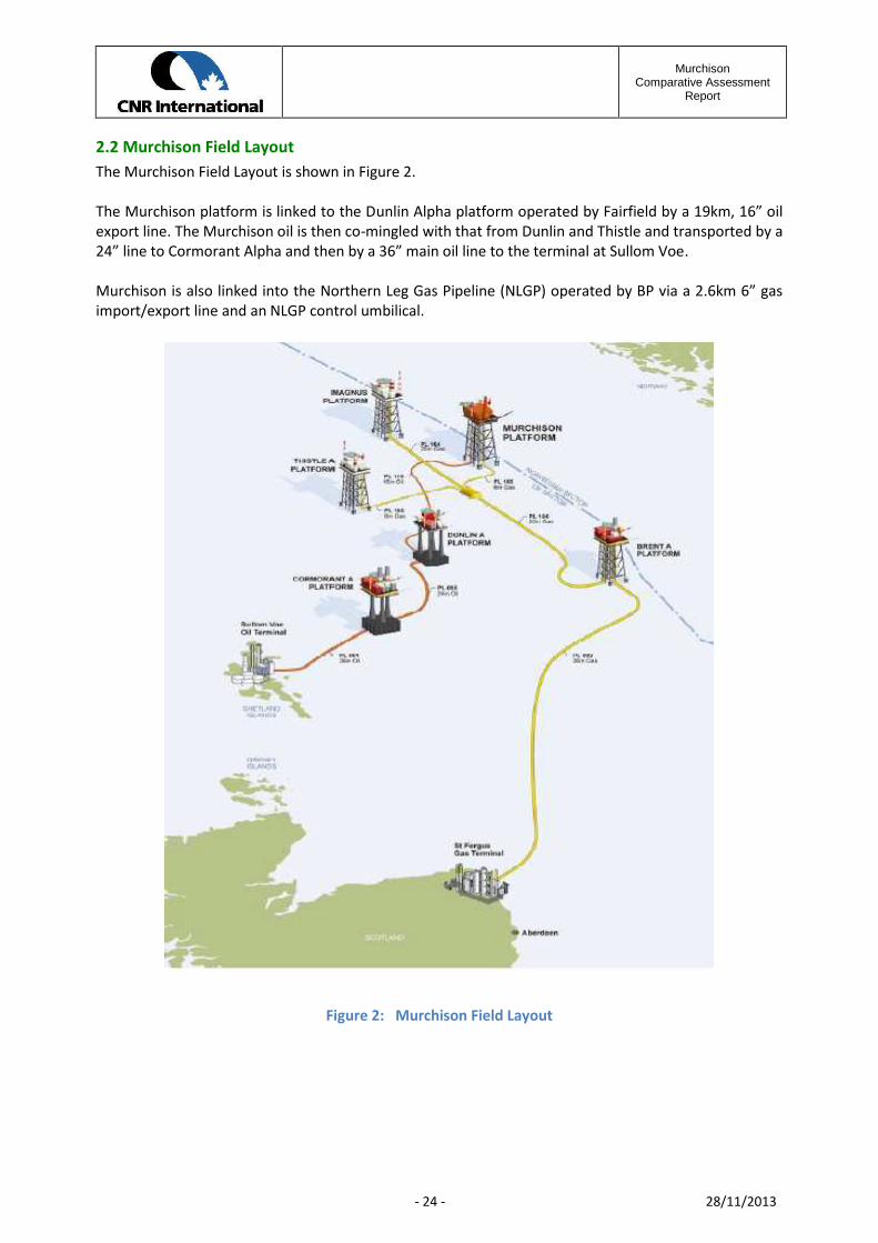
2.2 Murchison Field LayoutThe Murchison Field Layout is shown in Figure 2.
The Murchison platform is linked to the Dunlin Alpha platform operated by Fairfield by a 19km, 16” oilexport line. The Murchison oil is then co-mingled with that from Dunlin and Thistle and transported by a24” line to Cormorant Alpha and then by a 36” main oil line to the terminal at Sullom Voe.
Murchison is also linked into the Northern Leg Gas Pipeline (NLGP) operated by BP via a 2.6km 6” gasimport/export line and an NLGP control umbilical.
Figure 2: Murchison Field Layout

MurchisonComparative Assessment
Report
- 25 - 28/11/2013
2.3 Description of the Murchison PlatformThe Murchison platform, as shown in Figure 3 below, comprises a jacket structure supporting a modulartopsides.
2.3.1 The Murchison JacketThe jacket is an eight leg structure of welded steel construction and measuring 75m by 75m at the baseand 52.8m by 62.5m at the top. The overall height of the jacket is 188m.
Figure 3: Murchison Platform Components
The jacket foundations consist of 32 piles in groups of 8 around the four corner legs of the jacket. Eachpile is 82” in diameter and 80m in length and was designed to be driven some 50m into the seabed.Actual penetrations varied from 40m to 50m.
The piles were driven through pile sleeves which in turn were connected to the jacket by shear plates.
Steel mud mats were attached to the base of the jacket and pile sleeves to provide temporaryfoundations after the jacket had been installed and before the piles had been driven to the requireddepth.
MurchisonComparative Assessment
Report
- 26 - 28/11/2013
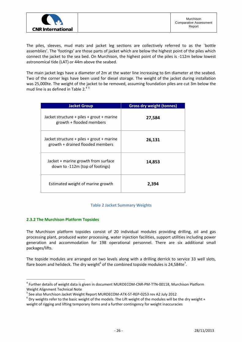
The piles, sleeves, mud mats and jacket leg sections are collectively referred to as the `bottleassemblies’. The 'footings' are those parts of jacket which are below the highest point of the piles whichconnect the jacket to the sea bed. On Murchison, the highest point of the piles is -112m below lowestastronomical tide (LAT) or 44m above the seabed.
The main jacket legs have a diameter of 2m at the water line increasing to 6m diameter at the seabed.Two of the corner legs have been used for diesel storage. The weight of the jacket during installationwas 25,000te. The weight of the jacket to be removed, assuming foundation piles are cut 3m below themud line is as defined in Table 2.4 5
Jacket Group Gross dry weight (tonnes)
Jacket structure + piles + grout + marinegrowth + flooded members
27,584
Jacket structure + piles + grout + marinegrowth + drained flooded members
26,131
Jacket + marine growth from surfacedown to -112m (top of footings)
14,853
Estimated weight of marine growth 2,394
Table 2 Jacket Summary Weights
2.3.2 The Murchison Platform Topsides
The Murchison platform topsides consist of 20 individual modules providing drilling, oil and gasprocessing plant, produced water processing, water injection facilities, support utilities including powergeneration and accommodation for 198 operational personnel. There are six additional smallpackages/lifts.
The topside modules are arranged on two levels along with a drilling derrick to service 33 well slots,flare boom and helideck. The dry weight6 of the combined topside modules is 24,584te7.
4 Further details of weight data is given in document MURDECOM-CNR-PM-TTN-00118, Murchison PlatformWeight Alignment Technical Note5 See also Murchison Jacket Weight Report MURDECOM-ATK-ST-REP-0253 rev A2 July 20126 Dry weights refer to the basic weight of the models. The Lift weight of the modules will be the dry weight +weight of rigging and lifting temporary items and a further contingency for weight inaccuracies

MurchisonComparative Assessment
Report
- 27 - 28/11/2013
Figure 4: Murchison Topside Configuration
7 Further details of weight data is given in document MURDECOM-CNR-PM-TTN-00118, Murchison PlatformWeight Alignment Technical Note

MurchisonComparative Assessment
Report
- 28 - 28/11/2013
Module Module Description Dry Weight[Mt]
Lift Weight[Mt]
M2 East Wellbay Module 1687 1940
M3 Flare Drums & Wellbay Module 1772 2038
M4 Separation Module 1342 1543
M5 Pipeline/Meters Module 1327 1526
M6 Compression Module 1681 1933
M7 Gas Sales Module 1392 1601
M8 Utilities Module 1247 1434
M9 Utilities Module 1378 1585
M10 Drilling Power 986 1134
M11 Drilling Mud Module 978 1125
M12 Derrick & Substructure Module 709 815
M13 Main Control & Workshop Module 1035 1190
M14 Main Power Generation Module 482 554
M15 Accommodation Module 1213 1395
M16 Accommodation Module 1104 1270
M17 Accommodation Module 402 462
M19 Flare Boom 213 245
M91 Helideck 257 296
M30a MSF & Cellar Deck East 2409 2770
M30b MSF & Cellar Deck West 2345 2697
Table 3 Murchison Topside Module - Removal Weights8
Estimated removal weights for the 20 major lifts are shown in Table 3.
Dry weights refer to the basic weight of the models with empty tanks and vessels. The Lift weight of themodules is the dry weight plus the weight of rigging and lifting temporary items and a furthercontingency for weight inaccuracies.
8 Topside Weight Review MURDECOM-ATK-ST-REP-00010

MurchisonComparative Assessment
Report
- 29 - 28/11/2013
2.4 Fabrication and Installation of the Murchison PlatformThis section of the report describes the process by which the Murchison Platform and associatedpipelines were fabricated, installed and commissioned during 1978 - 1980, and their present condition.
2.4.1 Fabrication of the Murchison JacketThe Murchison jacket was fabricated in the McDermott yard at Ardersier on the east coast of Scotland.
Figure 5: Layout of Jacket in Yard
The individual frames of the jacket were assembledhorizontally at ground level. The inner two jacket frameswere strengthened to provide the launch trusses that takethe whole jacket load during loadout of the jacket over thequay edge onto the cargo barge and the launch of the jacketwhen at the offshore location.
Figure 6: Roll up of Jacket Outer Frame
As each frame was completed it was rolled up into thevertical using a spread of synchronised crawler cranes. Thelargest frame to be rolled up into the vertical weighed over3,000 tonnes.
Figure 7: Installation of the Bottles Legs
The bottle leg assemblies comprising the main jacket lowerleg, pile sleeves, mud mat and connecting shear plates wereassembled in Japan and shipped to Ardersier. Each bottleassembly weighed approximately 3,000 tonnes. It wasoriginally planned to lift the bottles into position using aspecial built crawler crane.
However, during the initial lift the crane collapsed under the load and a special built portal frame wasconstructed to lift and hold it in position while final welding was completed.

MurchisonComparative Assessment
Report
- 30 - 28/11/2013
Figure 8: The Bottle Leg Assembly
The bottle leg assembly is shown here in its final positionafter fitting out. The pile sleeves are 2376mm diameter.
Figure 9: Jacket Prepared for Loadout
Figure 9 shows the Murchison jacket after fabricationcompleted being prepared for loadout onto a sea goingcargo barge. Before loadout temporary buoyancy tubeswere located in the jacket pile sleeves and the ballastcontrol system installed and commissioned.
The barge was grounded on a purpose built foundationpad in order to transfer the jacket load during loadout.
Figure 10: Loadout of the Murchison Jacket
Figure 10 shows the Murchison jacket prior to loadout. Thejacket was loaded out using purpose design launch trussesintegral with the jacket framing. The launch trusses werefitted with timber runners.
Figure 11: Jacket Being Towed to Site
After loadout onto the cargo barge the jacket was towedto the Murchison Platform site.
MurchisonComparative Assessment
Report
- 31 - 28/11/2013
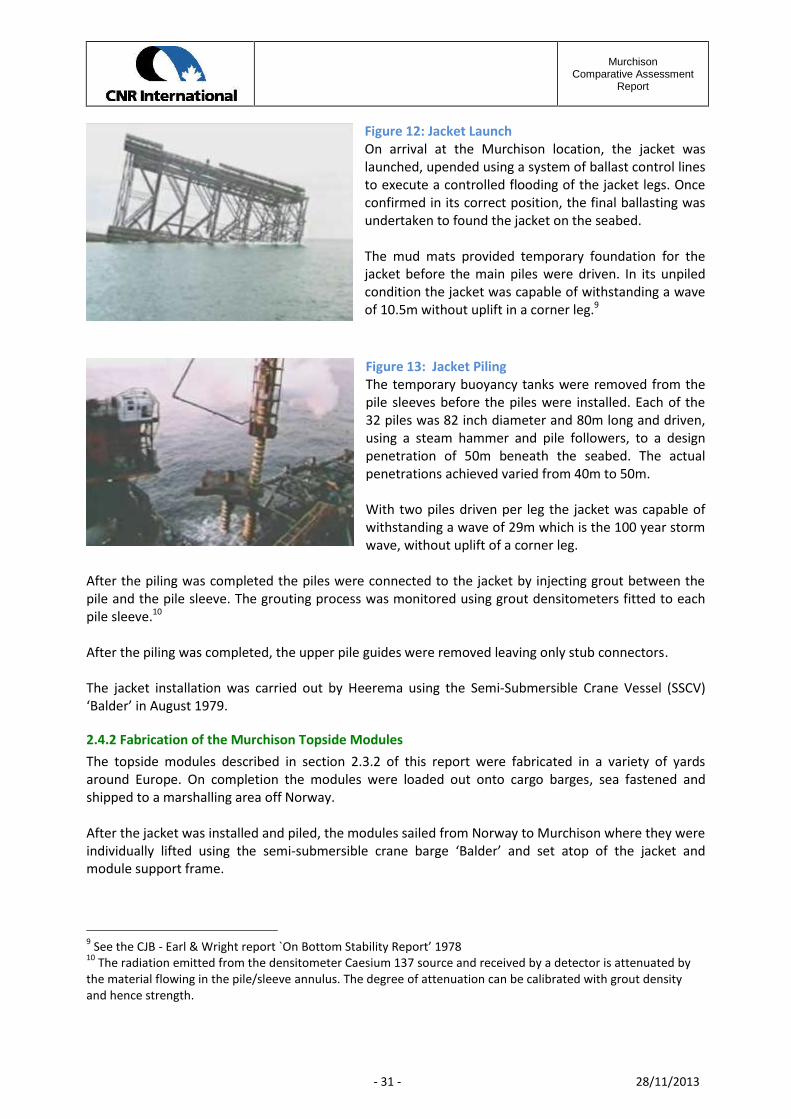
Figure 12: Jacket LaunchOn arrival at the Murchison location, the jacket waslaunched, upended using a system of ballast control linesto execute a controlled flooding of the jacket legs. Onceconfirmed in its correct position, the final ballasting wasundertaken to found the jacket on the seabed.
The mud mats provided temporary foundation for thejacket before the main piles were driven. In its unpiledcondition the jacket was capable of withstanding a waveof 10.5m without uplift in a corner leg.9
Figure 13: Jacket PilingThe temporary buoyancy tanks were removed from thepile sleeves before the piles were installed. Each of the32 piles was 82 inch diameter and 80m long and driven,using a steam hammer and pile followers, to a designpenetration of 50m beneath the seabed. The actualpenetrations achieved varied from 40m to 50m.
With two piles driven per leg the jacket was capable ofwithstanding a wave of 29m which is the 100 year stormwave, without uplift of a corner leg.
After the piling was completed the piles were connected to the jacket by injecting grout between thepile and the pile sleeve. The grouting process was monitored using grout densitometers fitted to eachpile sleeve.10
After the piling was completed, the upper pile guides were removed leaving only stub connectors.
The jacket installation was carried out by Heerema using the Semi-Submersible Crane Vessel (SSCV)‘Balder’ in August 1979.
2.4.2 Fabrication of the Murchison Topside ModulesThe topside modules described in section 2.3.2 of this report were fabricated in a variety of yardsaround Europe. On completion the modules were loaded out onto cargo barges, sea fastened andshipped to a marshalling area off Norway.
After the jacket was installed and piled, the modules sailed from Norway to Murchison where they wereindividually lifted using the semi-submersible crane barge ‘Balder’ and set atop of the jacket andmodule support frame.
9 See the CJB - Earl & Wright report `On Bottom Stability Report’ 197810 The radiation emitted from the densitometer Caesium 137 source and received by a detector is attenuated bythe material flowing in the pile/sleeve annulus. The degree of attenuation can be calibrated with grout densityand hence strength.

MurchisonComparative Assessment
Report
- 32 - 28/11/2013
Figure 14: Installation of Topside Modules
On arrival by barge to the Murchison platform, eachmodule was rigged up, lifted clear of the barge andset onto the module support frame (MSF).
Figure 15: First Topside Module Installed
Figure 15 shows the first module to be set down ontothe MSF.
Figure 16: Second Level of Modules Being Installed
Figure 17: Hook Up and Commissioning of Modules
After installing all of the modules, an accommodation vesselwas moored alongside the Murchison platform to supportthe hook up and commissioning (HUC) teams in a 34-weekprogramme.
Hook up and commissioning entails installing all theinterconnecting access ways, pipe work, cables and utilitiesbetween modules and their final testing and commissioningbefore hand over to the platform operating teams.

MurchisonComparative Assessment
Report
- 33 - 28/11/2013
2.4.3 Murchison Jacket Condition SurveyThe latest jacket condition survey was completed in 201111. The General Visual Inspection (GVI)reported the jacket structure to be in a good condition with no gross damage or significant distortions.Key conclusions for the comparative assessment process were noted as:
a) All 32 piles in four clusters of 8 per leg were inspected. The majority have internal access forcutting the piles below seabed level, after removing internal soil plugs, but 7 were found tohave debris located in the pile which would have to be fished out before a cutting tool could berun inside the pile.
b) The height of each of the 32 piles protruding above the pile sleeve, in which they are located,was measured. The level of the highest pile (A2/7) was at an elevation of approximately 112mbelow sea level. This level sets the datum for the top of footings.
c) All 10 leg ballast control valves, used to control buoyancy during jacket upend, were generallyfound to be in good condition, although access was restricted due to the extent of the Lopheliapertusa marine growth.
d) The 72 grout densitometers fitted to the pile sleeves were found to be in good conditionalthough access was restricted by extensive Lophelia marine growth.
e) Flooded member checks were completed, the inner jacket legs being flooded, whilst the cornerlegs were dry with the exception of the top compartments in legs A2 and E2 which were usedfor diesel storage.
f) The jacket launch truss timber runners were found to be in good condition with no visibledamage.
g) A debris survey within the 500m safety zone identified 345 targets in excess of 1m in length by1m in width and/or height. The targets were a mixture of 164 oilfield related debris and 181naturally occurring boulders.
h) Periodic surveys have confirmed details of the extent and type of marine growth on the jacketstructure and appurtenances.12 13
2.4.4 Murchison Topside Condition Survey14
The 2010 topside condition survey found no major defects on the topsides structure and overall thestructure appeared to be in an acceptable condition. It was apparent that some fabric maintenance was
11 For detailed survey results see section 9 of the 2011 Pipeline Inspection and Environmental Survey Report – PLS-ISS-SU-REP-1543012 CNR Structural Integrity –Marine Growth NNS-ATK-ST-TEC-014013 Evaluation of the Extent of Colonisation of Lophelia pertusa and Marine Growth on the Murchison platform –2010 ref doc A.INS.001/Murchison14 For detail survey results see CNRI Assets Topside Structural Integrity Survey 2011 Report – MUR-ATK-ST-REP-0227

MurchisonComparative Assessment
Report
- 34 - 28/11/2013
being performed but there remained areas of the structure, particularly the stair towers, showingcoating breakdown and/or corrosion.
Further topside condition surveys will be undertaken during the course of the pre-engineering phase ofthe Murchison decommissioning project.
2.5 Murchison Pipeline InfrastructureThe Murchison Platform ties into a pipeline infrastructure as shown below in three principalconfigurations:
a) The pipeline bundles PL123, PL124 and PL125 which formed part of the earlyproduction facilities.
b) The Oil Export Pipeline (OEL) PL115 which exports produced oil to Dunlin and then ontoSullom Voe terminal via the Cormorant Platform.
c) The Murchison Platform imports gas from the BP-operated NLGP network via PL165and associated control umbilical. These lines will be decommissioned at a later date aspart of the NLGP system and are therefore not part of the Murchison Programme.
The PL115 oil export line (OEL) runs under15 a number of existing pipelines, including:
15 For crossing details see NLGP Handover Documents – ‘As Built drawings – Vol 1 1984 and for the Penguin linessee Shell Penguin Gas Lift Project doc ref PENGL/25/UK006524/402/)F-3/004
Figure 18: Murchison Subsea Infrastructure
MurchisonComparative Assessment
Report
- 35 - 28/11/2013
a) The 20 inch diameter PL164 from Magnus to Brent operated by BP
b) The 16 inch diameter PL1902 from Penguins to Brent operated by Shell
c) The 4 inch diameter PL2228 from Penguins to Brent operated by Shell
d) The 6 inch diameter PL 166 Spur to Thistle operated by BP and associated umbilical
e) The 4 inch diameter PL2852 gas line from Thistle to Dunlin operated by Fairfield
f) The Penguin/Brent C PLU1903 SSIV control umbilical
It is anticipated that at the time of decommissioning of the PL115 line, all of the pipelines noted abovewill continue in operation. As a consequence, any decommissioning work on PL115 will need the prioragreement of BP, Shell and Fairfield as operators of the crossing lines. As PL115 ties into the DunlinPlatform, any decommissioning work within the Dunlin 500m safety zone will require the agreement ofFairfield as the Dunlin operator. There are well established protocols for negotiating ProximityAgreements.
2.5.1 Murchison Pipeline Bundles16
The Murchison Pipeline Bundles17 were conceived as part of an early production concept of tying insubsea appraisal wells to the platform to produce oil while the main drilling programme commencedusing the platform facilities.
Pipeline Description From To Diameter WallThickness
Length
PL 123 Early production flow line, with 2 x3.5” dia flowlines and 4 controlumbilicals in a carrier pipe
Well211/19-2
MUR 324mm 6.35mm 792.5m
PL 124 Early Water Injection flow line,with 2 x 3.5” dia flowlines and 4control umbilicals in a carrier pipe
Well211/19-3
MUR 324mm 6.35mm 2,012.0m
PL 125 Early Production flow line, with 2 x3.5” dia flowlines and 4 controlumbilicals in a carrier pipe
Well211/19-4
MUR 324mm 6.35mm 1,237.5m
Table 4 Pipeline Bundle Summary Details
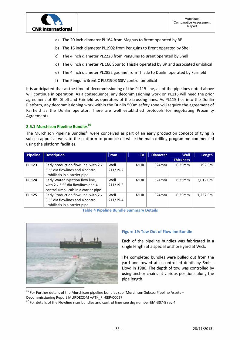
Figure 19: Tow Out of Flowline Bundle
Each of the pipeline bundles was fabricated in asingle length at a special onshore yard at Wick.
The completed bundles were pulled out from theyard and towed at a controlled depth by Smit -Lloyd in 1980. The depth of tow was controlled byusing anchor chains at various positions along thepipe length.
16 For Further details of the Murchison pipeline bundles see `Murchison Subsea Pipeline Assets –Decommissioning Report MURDECOM –ATK_PI-REP-0002717 For details of the Flowline riser bundles and control lines see drg number EM-307-9 rev 4
MurchisonComparative Assessment
Report
- 36 - 28/11/2013
On arrival at the Murchison platform, the bundles were flooded down onto the seabed and tied into theplatform by Subsea Offshore in 1980.
The early production wells were shut-in in 1982 and the pipeline bundles registered under the disusedpipeline notification scheme.
The bundles PL124 and PL 125 were disconnected from their subsea wells in 1982 using divers and leftopen to the sea. PL123 remains connected to the well 211/19-2 and will require pressure and fluidmonitoring ahead of any disconnection.
Recent surveys indicate all three Murchison bundles are exposed on the seabed with some spanning18
and local damage19 to the bundle carrier pipes.
2.5.2 Murchison Pipeline PL115PL115 is the main oil export line (OEL) that runs 19.2 km from the Murchison platform to Dunlin.
Crude oil processed on the Murchison platform is transported 19.2km south-west to Dunlin Alpha(Fairfield Energy-operated) where the flow combines with that of Thistle (Enquest-operated) and DunlinAlpha production before passing into a 24 inch pipeline to Cormorant Alpha (Taqa-operated). FromCormorant Alpha, the oil is transported through the Brent Pipeline System to the BP-operated SullomVoe Terminal on the Shetland Islands via the 36 inch MOL (Main Oil Line).
PL115 consists of a 16 inch (406mm) diameter by 0.625 inch (15.9mm) wall thickness (WT) pipe madefrom 5LX Grade X60 steel. The pipeline is weight coated with 2.25 inches (57.2mm) of concrete which isreinforced with 8mm diameter circumferential steel bars and 5mm longitudinal steel bars (rebar).
The coated pipe was shipped out to the Brown and Root lay barge – ‘Semac 1’ – in 12m lengths. Theindividual lengths were joined and run out over the stinger in a lazy-S configuration to lie on the seabed.
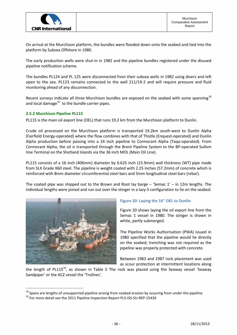
Figure 20: Laying the 16" OEL to Dunlin
Figure 20 shows laying the oil export line from theSemac 1 vessel in 1980. The stinger is shown inwhite, partly submerged.
The Pipeline Works Authorisation (PWA) issued in1980 specified that the pipeline would lie directlyon the seabed; trenching was not required as thepipeline was properly protected with concrete.
Between 1983 and 1987 rock placement was usedas scour protection at intermittent locations along
the length of PL11520, as shown in Table 5 The rock was placed using the Seaway vessel ‘SeawaySandpiper’ or the ACZ vessel the ‘Trollnes’.
18 Spans are lengths of unsupported pipeline arising from seabed erosion by scouring from under the pipeline19 For more detail see the 2011 Pipeline Inspection Report PLS-ISS-SU-REP-15430
MurchisonComparative Assessment
Report
- 37 - 28/11/2013
Figure 21 shows the transition between exposed section of pipeline and pipeline under rock cover.Full survey results of PL115 are available in the 2011 ISS Pipeline Survey Report PLS-ISS-SU-REP-15430.
The survey reported 73 areas of damage to the pipeline which included 15 areas of exposed rebar and56 area showing areas of concrete spalling. Portions of PL115 have shown depleted anodes withconsequential internal and external corrosion.
start finish exposed length rock dumped lengthkm km m m
0 1.45 1450 Murchison 500 m zone1.45 1.6 150
1.6 1.78 1801.78 1.81 301.81 3.77 19603.77 4.4 630
4.4 4.75 3504.73 5.35 6205.35 7 1650
7 7.075 757.1 7.2 1007.2 7.73 530
7.73 8.2 4708.2 8.95 750
8.95 9.5 5509.5 11.65 2150
11.65 11.8 15011.8 11.95 150
11.95 12.3 35012.3 12.7 40012.7 14.28 1580
14.28 14.45 17014.45 14.68 23014.68 14.73 5014.73 14.8 70
14.8 15.35 55015.35 15.55 20015.55 15.75 20015.75 18.26 251018.26 19.2 940 Dunlin 500 m zone
8645 1055019195
Table 5 Extent of Rock Placement during 1985 to 1987
20 For detail information on the scour protection see Technical Note: Murchison Comparative Assessment, PostWorkshop Actions - PL115 MURDECOM-CNR-PM-GTN-00226
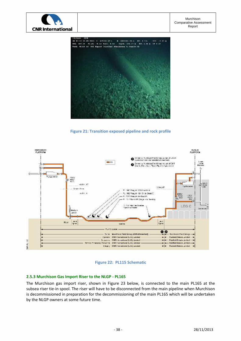
MurchisonComparative Assessment
Report
- 38 - 28/11/2013
Figure 21: Transition exposed pipeline and rock profile
Figure 22: PL115 Schematic
2.5.3 Murchison Gas Import Riser to the NLGP - PL165The Murchison gas import riser, shown in Figure 23 below, is connected to the main PL165 at thesubsea riser tie-in spool. The riser will have to be disconnected from the main pipeline when Murchisonis decommissioned in preparation for the decommissioning of the main PL165 which will be undertakenby the NLGP owners at some future time.
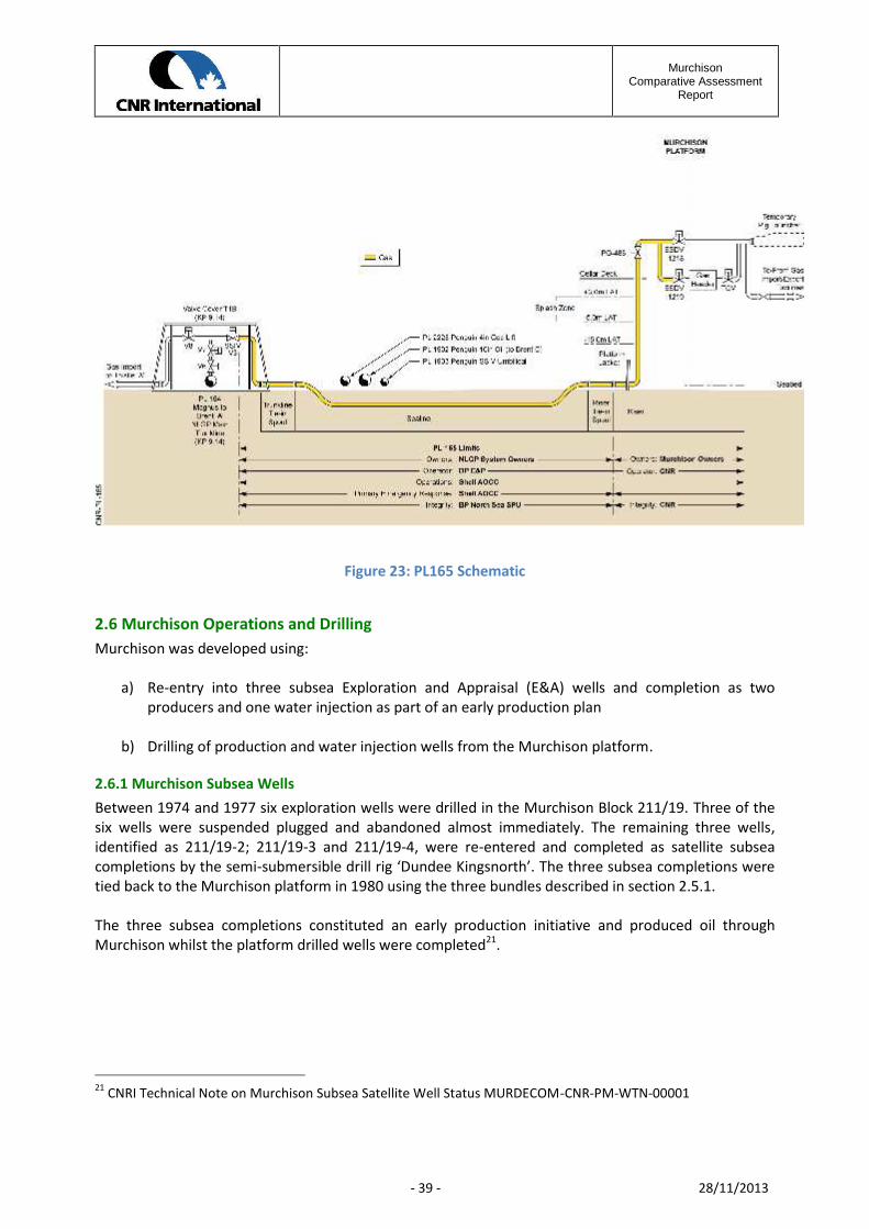
MurchisonComparative Assessment
Report
- 39 - 28/11/2013
Figure 23: PL165 Schematic
2.6 Murchison Operations and DrillingMurchison was developed using:
a) Re-entry into three subsea Exploration and Appraisal (E&A) wells and completion as twoproducers and one water injection as part of an early production plan
b) Drilling of production and water injection wells from the Murchison platform.
2.6.1 Murchison Subsea WellsBetween 1974 and 1977 six exploration wells were drilled in the Murchison Block 211/19. Three of thesix wells were suspended plugged and abandoned almost immediately. The remaining three wells,identified as 211/19-2; 211/19-3 and 211/19-4, were re-entered and completed as satellite subseacompletions by the semi-submersible drill rig ‘Dundee Kingsnorth’. The three subsea completions weretied back to the Murchison platform in 1980 using the three bundles described in section 2.5.1.
The three subsea completions constituted an early production initiative and produced oil throughMurchison whilst the platform drilled wells were completed21.
21 CNRI Technical Note on Murchison Subsea Satellite Well Status MURDECOM-CNR-PM-WTN-00001

MurchisonComparative Assessment
Report
- 40 - 28/11/2013
The survey of the subsea wells conducted in 201122 confirmed the following:
211/19-2 – Subsea, the pipeline end remains connected to wellhead. Wellhead protection coverremains in situ. At the platform, the riser / flowline subsea connector remains in situ. On the platformtopsides, the Cameron tree has been removed leaving the outer casing and 4-off control linesterminating at +24m level and the Cameron hub with flowlines terminating at +33m level.
211/19-3 – Subsea, the end connections of each flowline at wellhead have been removed, with thebundle-end lying on seabed. Two bends/associated buckles have been observed at the wellhead end ofthe bundle. At the platform, the riser / flowline subsea connector remains in situ. On the platformtopsides, the termination to the Cameron tree remains in situ, with pipe work removed downstream.The subsea tree and structure have been removed and a 1m section of casing remains above theseabed.
211/19-4 – Subsea, the flowline has been cut just short of the wellhead, with the bundle-end lyingundisturbed on seabed. It should be noted that whilst the wellhead tree has been removed, theproduction guide base (PGB) remains in place and the protection structure is located to the east of thestructure. At the platform, the riser/flowline subsea connector remains in situ. On the platformtopsides, the termination to the Cameron tree remains in situ, with pipe work removed downstream ofthe tree.
A schematic of the wellhead protection structure is shown in Figure 24.
Protection Frame
Space Frame
FoundationPiles Grouted
into Drilled Hole
Subsea Tree
Figure 24: 211/19-2 Subsea Installation
The subsea installation 211/19-4 is similar, but the protection frame is set on the seabed beside thespace frame and subsea tree.
22 Survey results are reported in ISS Pipeline and Subsea Survey – Phase 2 Report PLS-ISS-SU-REP-15430
MurchisonComparative Assessment
Report
- 41 - 28/11/2013
2.6.2 Murchison Platform Wells and Characteristics of the Drill Cuttings PileThe total number of development wells drilled to date on Murchison is through the existing 33 slots,which includes the satellite wells drilled to Playfair (M71) and the Delta area (M75 series – Norwegiansector).
Currently, 18 slots are active producers and 13 slots are injectors, with two slots (M16 and M50) whichare abandoned due to integrity issues with the wellbores. The layout and designation of wells is shownin Figure 25.
Figure 25: Murchison Well Slot Diagram
The history of individual wells and their current status isdescribed in MURDECOM-CNR-PM-REP-00015.
Figure 26: Drilling Production Wells on Murchison
During the life of the platform, approximately 22,545m3
of cuttings have been discharged to the sea. Of the 33well slots drilled in this field, oil based mud (OBM) wasused and discharged with drill cuttings at half of thewells23 .
23 Technical Review of Data from CNR’s North Sea Assets with regards to OSPAR recommendations 2006/5 – ERTreport 1881-2008
MurchisonComparative Assessment
Report
- 42 - 28/11/2013
A proportion of these discharged drill cuttings and drilling mud now exist as a pile on the seabedimmediately below the jacket, covering the bottom bracing.
The top hole sections (36 and 26 inch) of all 33 platform wells were batch drilled in 1980 using waterbased mud, with mud and drill cuttings discharged directly to the seabed and forming the base of thepile.
The lower hole sections (17.5 - 8.5 inches) were primarily drilled with oil based mud (OBM) thecomposition of which has changed over time due to advances in the mud technologies used andchanges in the regulatory regime.
The discharge of OBM was normal practice in the first two decades of offshore drilling in the North Sea,normally using diesel as the oil, but concerns over its environmental impacts led to restrictions on itsdischarge. The use of diesel in discharges of drilling mud was prohibited from 1984 onwards and in itsplace alternative oils were used that had similar properties but with a lower content of aromaticcompounds. These muds were known as low-toxicity oil-based muds (LTOBM). They were used foraround a decade, but still contained a significant aromatic content including polycyclic aromatichydrocarbons (PAH) which are relatively toxic.
Up to 1996 the discharge of such muds was phased out and they were replaced with oils that wereentirely synthetic in origin (synthetic based mud, SBM) with lower levels of aromatic hydrocarbons(virtually zero). Finally the discharge of SBMs was phased out and banned from 2001 onwards, withsome exceptions that do not apply to Murchison. Since 2001 all OBM and OBM-contaminated cuttingshave either been re-injected or returned to shore for disposal.
For the purposes of the Murchison comparative assessment process, the following assumptions havebeen made on the mud types used in modelling the drill cuttings pile:
Period assumed No wells drilled incl side tracksWBM top-hole sections <1980 33Early WBM 1980-1984 3Diesel OBM 1980-1983 20LTOBM 1984-1996 15SBM 1996-2001 19OBM retained 2001-present 22
Table 6 Assumed History of Murchison Drilling Muds
During the pre-decommissioning environmental baseline survey in 2011 the Murchison drill cuttingspile was surveyed using MBES (Multi-Beam Echo Sounder) to map the topography of the pile, and sixROV-operated push cores were collected. Three cores were used for faunal analysis, and three wereused to characterise the physical and chemical composition of the pile24 .
The results of the MBES survey indicate that the pile is located under and to the southeast of theMurchison platform extending in a south-easterly direction following the main residual current. The pile
24 2011 Pipeline Inspection and Environmental Survey Report PLS-ISS-SU-REP-15430

MurchisonComparative Assessment
Report
- 43 - 28/11/2013
is located against and around the eastern leg of the Murchison jacket and covers the lower horizontaland vertical braces of the jacket.
The footprint area and volume of the Murchison cuttings pile were calculated as 6,840m2 and 22,545m3
respectively, shown below.25
Extent of the pile
Water Depth(m)
Murchison platformstructure
N
Distance (~40m)
-156 m
-139 m
Extent of the pile
Water Depth(m)
Murchison platformstructure
N
Distance (~40m)
-156 m
-139 m
Figure 27: MBES Survey Data of the Murchison Drill Cuttings Pile
25 For details of the drill cutting pile see the Environmental Assessment of Options for the Management of theMurchison Drill Cuttings Pile MURDECOM-BMT-EN-STU-00132
MurchisonComparative Assessment
Report
- 44 - 28/11/2013
2.7 The Murchison Environmental Setting26
Figure 28: Murchison Environmental Setting
Figure 29: Jacket Key Plan
26 For more detailed information see Environmental Statement for the Decommissioning of the MurchisonFacilities – Environmental Description MURDECOM-BMT-EN-REP-00126

MurchisonComparative Assessment
Report
- 45 - 28/11/2013
2.7.1 Bathymetry
Water depth at the Murchison field is approximately 156m. The seabed in the vicinity of Murchison ismainly flat with a northwards gentle slope from about 150m to 200m.
Figure 30: Bathymetry Map of the Murchison Area
2.7.2 Seabed Sediments
Table 7 gives average soils data across the Murchison Area used in the assessment of the jacket footingsintegrity for different removal options, and for the technical assessment of pipeline trenching options.
Depth Description Wet Density t/m3 Shear StrengthKn/m2
0-1m(varies)
Grey medium to fine sands with some coarsesand and gravel. Large number of surfaceboulders
2.21
1 - 2.7m Stiff finally laminated grey sandy very silty clay(boulder clay) with occasional shell fragments
2.06 126
2.7 - 3.8m Very stiff laminated very dark grey sandy verysilty clay
2.08 75 -285
3.8 - 4.7m Very stiff laminated very dark grey sandy verysilty clay with occasional chalk fragments
2.08 150 - 260
Table 7 Average Values across Boreholes27
27 Report on Laboratory Testing – Murchison Field -1977 Fugro

MurchisonComparative Assessment
Report
- 46 - 28/11/2013
2.7.3 Extreme Metocean Criteria28
Table 8 summarises the extreme Metocean conditions used in the technical and risk assessments of theMurchison jacket removal options.
WINDS 1-Year 10-Year 50-Year 100-Year 1,000-Year 10K-Year
Wind Speeds at 10m asl [m/s]V ( 1-hr ) 30.1 34.4 37.2 38.4 42.0 45.5
V ( 10-min ) 33.1 38.2 41.5 42.9 47.2 51.4
V ( 1-min ) 37.1 43.0 46.9 48.7 53.9 59.0
Gust ( 3-sec ) 42.1 49.3 54.1 56.2 62.6 69.0
WAVES 1-Year 10-Year 50-Year 100-Year 1,000-Year 10K-Year
Wave Heights [m]Hs 10.9 13.2 14.8 15.5 17.8 20.1
Hmax (3 hr) 20.0 24.0 27.1 28.3 32.5 36.7
Crest (rel mean sample level) 12.1 14.6 16.4 17.2 19.8 22.3
CURRENTS 1-Year 10-Year 50-Year 100-Year
Total Current Profile [m/s]Surface 0.51 0.58 0.62 0.64
75% of water depth 0.51 0.58 0.62 0.64
50% of water depth 0.51 0.58 0.62 0.64
20% of water depth 0.44 0.50 0.54 0.56
5% of water depth 0.36 0.41 0.45 0.46
0.01% (near seabed) 0.30 0.34 0.37 0.38
WATER LEVELS The following parameters do not vary with return periodTidal Height (LAT) [m]HAT 2.00
MHWS 1.67
MHWN 1.30
MSL 0.99
MLWN 0.68
MLWS 0.31
LAT 0.00
1-Year 10-Year 50-Year 100-Year 1,000-Year 10K-Year
Positive Surge Levels (MSL) [m] 0.52 0.65 0.73 0.76 0.84 0.90
Still Water Level (LAT) [m] 2.30 2.40 2.45 2.47 2.51 2.53
Extreme Water Level (LAT) [m](Crest + associated SWL) 13.8 16.3 18.1 18.9 21.4 24.0
Table 8 Extreme Metocean Data29
28 For full Metocean data see report Metocean Criteria For Murchison-Design Criteria doc ref C319-R413-1029 Metocean Criteria For Murchison Vol 1- Design Criteria - 2010 doc ref PhysE Re C319-R-413-10

MurchisonComparative Assessment
Report
- 47 - 28/11/2013
2.8 Marine Activity around Murchison30
2.8.1 Adjacent Oil and Gas InfrastructureOil and gas developments in the area adjacent to Murchison are relatively intense, as described insection 2.2 above. The interdependence within the local oil and gas infrastructure has been addressedparticularly with regard to the export of oil product from Murchison to Dunlin; the import of fuel gasfrom the NLGP system and the numerous pipeline crossings which will impact the available options fordecommissioning of PL115.
2.8.2 Shipping31
The Murchison Field is located in an area of moderate to low shipping activity. There are four shippinglanes in the vicinity of Block 211/19 with an average shipping density of 0.5 to 10 vessels per day. Theshipping lanes are used primarily by shuttle tankers, supply and standby vessels serving the offshoreindustry.
2.8.3 DefenceThere is no known military activity in the vicinity of the Murchison Field, nor any recorded munitionsdumping grounds.
2.8.4 Telecommunications and CablesThere are no known submarine telecommunication and power cables within the vicinity of theMurchison Field.
2.8.5 WrecksThere are no recorded wrecks in the vicinity of the Murchison Field.
2.8.6 FishingThe relative UK fishing effort in the Murchison area (ICES rectangles 51F1 and 52F1) in 2010 was verylow in comparison with other areas of the North Sea.
A detailed analysis of the fishing effort around Murchison is reported in the Commercial Fisheries –Socioeconomic Impact Study – document ref MURDECOM –SFF–EN–ST-00131.
The commercial fishing industry is subject to frequent changes in legislation and policy and, as a result,it is difficult to predict future levels, patterns and practices, over the timescale of the decommissioningproject particularly where an assessment of long term residual impacts is being considered.
It is likely that there will also be changes to fisheries management policies on international, nationaland regional levels that will impact fishing activities in the area. Of particular importance is theproposed reform of the Common Fisheries Policy (CFP), which could potentially bring in a change to theway commercial fisheries are managed.
30 For details of Marine Activity data in the vicinity of Murchison see the DTI - Strategic Environmental Assessmentof the Mature Area of the North Sea SEA2 - 200131 Ref Murchison Shipping Traffic Survey – Anatec - MURDECOM-ATC-EN-STU-00199

MurchisonComparative Assessment
Report
- 48 - 28/11/2013
2.8.7 Annex 1 HabitatsAlthough specimens of the cold water, reef building coral Lophelia pertusa were evident on parts of theMurchison jacket, no evidence of sub tidal reefs, submarine structures or any other potential Annex IHabitats were found across the rest of the survey area of the platform or along the length of PL115.

MurchisonComparative Assessment
Report
- 49 - 28/11/2013
3 Murchison Decommissioning OptionsThis section provides a description of the process by which decommissioning options were identified,screened and taken forward for assessment.
3.1 Post CoP Alternate Use OptionsDuring the Murchison Life of Field strategic planning, a number of initiatives to extend the fieldoperating life were examined by CNRI including enhanced oil production technology, drilling to reachstranded reserves and potential third party tie backs. None of the initiatives examined was found to becommercially viable and consequently a Cessation of Production (CoP) Application was submitted toDECC in 2011, approved in 2012, and decommissioning planning commenced.
Three key strategic options were assessed, namely:
a) Could the Murchison platform be relocated to a new oil/gas exploration and production area?
If not, then
b) Could an alternate use be found for the Murchison Platform in its present location?
If not, then
c) What were the decommissioning options?
3.1.1 Relocation and Reuse of Murchison Platform32
The Murchison platform was installed in 1978 in UKCS Block 211/19 and lies approximately 150kmnortheast of Shetland in 156m water depth. It was originally designed for a service life of 20 years withan anticipated decommissioning date of 1998.
The main issue with reuse of the Murchison platform as an oil and gas production facility is the highcost of maintaining the fabric and structural integrity of the platform and its operating componentswhich are subject to fatigue damage and degradation caused by corrosion.
The platform process systems were designed using 1970’s technology which has moved on significantlysince that time, so major replacement of process and utility systems would be required in a re-usescenario. This would be unviable.
Relocation of the platform to another site for re-use as an oil and gas producing platform was thereforeconsidered impractical because of the condition size and age of the platform and hence was notconsidered further.
32 A detailed study was undertaken to review re-use of the Murchison platform, the results from which arereported in the document `Post CoP Alternate Use Appraisal’ – DECOM-GLD-PM-STU-00048

MurchisonComparative Assessment
Report
- 50 - 28/11/2013
With no viable reuse options identified, three main alternate use options were identified:
1. Alternate use for wind energy
2. Alternate use for wave and tidal energy
3. Alternate use for carbon capture and storage.
3.1.2 Potential Alternate Reuse for Wind EnergyOne option investigated33 was to remove the Murchison topsides to shore and then use the jacketstructure as a support for one or more wind turbine generators (WTGs).
Figure 31: Concept for a 10MW Vertical Axis Turbine
The largest WTGs to date have a rotordiameter of up to 150m with a generatingpotential of 6MW, although there aredevelopment projects in hand for the designof 10MW WTGs. The other factor to takeinto account is the capacity factor of theWTG. This is a function of wind strength andis location dependent. The Murchisonplatform is in an exposed offshore locationand would have a capacity factor of around0.45. On this basis it is estimated thatMurchison could generate up to 39,420MWhper annum for up to 25 years.
It would require laying over 150km of high voltage direct current (HVDC) subsea cable for transmissionof power to shore, with a substation located on the jacket.
A simple economic model was created to assess the commercial viability of converting Murchison towind generation. This was based on the following assumptions:
Energy generated 39, 420 MWh paTransmission efficiency 0.9Basic Power price £55.00/MWhRenewable Obligation Certificate (ROC)34 £50.00/MWhROC band 1.5Levy Exemption Certificate (LEC)35 £4.30
33 For details see Post CoP Alternate Use Appraisal – DECOM-GLD-PM-STU-0004834 Renewable Obligation Certificates (ROCs) are green certificates issued by Ofgem to operators of accreditedrenewable generating stations for the eligible renewable electricity they generate35 Renewable Levy Exemption Certificates (Renewable LECs) are electronic certificates issued by Ofgem toaccredited generating stations for each Megawatt/hour (MWh) of renewable source electricity generated. LECsidentify renewable source electricity produced by accredited renewable generating stations

MurchisonComparative Assessment
Report
- 51 - 28/11/2013
On this basis:
1. Total income is then 39420 * 0.9* (£55 + £50*1.5 +£4.3) = £4,765,000 pa2. The capital cost for procurement of the WTG, support equipment, transmission cable
including installation is approximately £55,000,0003. The annual running costs, including maintenance of the jacket is estimated at £3,060,000pa4. The operating life of the WTG is estimated at 25 years. Over this period of time the annual
maintenance costs will escalate at around 5% pa reflecting the age of the jacket and theneed for more extensive and more costly repairs.
Entering this data into an economic model and discounting at 10% gave a Net Present Value36 of minus£36.5m, which is a not a commercially sound proposition, at least in the near future and consequentlywas not considered further.
3.1.3 Potential for Wave & Tidal EnergyThe potential for converting the Murchison Platform to wave and or tidal energy generation was alsoassessed37.
Figure 32: Seagen Drive
There are two principal ways of harnessing tidalenergy either by converting the kinetic energy of tidalcurrents or by converting the potential energy in thewater level tidal variations. The kinetic energy of tidalcurrents is converted using S-turbine type devicessuch as the Seagen device.
The Murchison platform is in a location of negligibletidal power resource and for this reason the use ofthe existing structure for tidal energy is discounted.
The methods of converting wave energy to electricalenergy are diverse, but in deep water the devicestend to be floating or tethered to the seabed such asthe Pelamis Wave Energy Converter.
Figure 33: Pelamis Device Prototype
36 NPV can be described as the “Difference Amount” between the sums of discounted cash inflows and cashoutflows. It compares the present value of money today to the present value of money in future, taking inflationand returns into account37 For details see ‘Post CoP Alternate Use Appraisal’ – DECOM-GLD-PM-STU-00048

MurchisonComparative Assessment
Report
- 52 - 28/11/2013
Pelamis is a semi-submerged articulated structure linked by hinge joints. The wave induced motion ofthe joints is resisted by hydraulic rams which pump high pressure fluid through hydraulic motors. Thehydraulic motors in turn drive electrical generators to produce electricity.
Assuming a device, similar to Pelamis could be attached to the Murchison jacket, the maximum wavecrest width from which the energy is extracted would be around 60m long, being a function of thejacket dimensions.
In the area around Murchison the annual mean wave power would be approximately 40kW/m wavecrest. This equates to 60* 40kW/m or 2400kW (2.4MW) Applying a wave to electrical energy conversionefficiency of 50% and 8760 hours pa (365 *24) gives an expected annual energy generated of = 2.4 *50% * 8760 = 10,512 MWh pa.
Again using a simple economic model, assuming:
1. Energy generated 10,512 MWh pa2. Basic Power price £55.00/MWh3. Renewable Obligation Certificate (ROC)38 £50.00/MWh4. ROC band 2.05. Levy Exemption Certificate (LEC)39 £4.30
Then:
1. Total income is £10,512* (£55 + £50*2.0 +£4.3) = £1,675,000 pa
2. The capital cost for procurement of the WTG, support equipment, transmission cable includinginstallation is approximately £55,000,000, similar to that for wind energy
3. Likewise, the annual running costs, including maintenance of the jacket is estimated at£3,000,000pa
The annual operating costs alone are more than double the annual income from wave energygeneration. Therefore the use of the existing Murchison platform for wave generation is not consideredto be a commercially viable option, and was not considered further.
3.1.4 Potential for Carbon CaptureConcerns regarding the impact of rising carbon dioxide (CO2) levels on the climate have resulted in anumber of initiatives directed towards the stabilisation and eventual reduction of CO2.
Carbon Capture and Storage (CCS) is a process involving the capture of carbon dioxide from the burningof fossil fuels and its transportation and storage in secure spaces, such as geological formations, underthe seabed. Primary aspects of CCS for Murchison addressed the following issues:
38 Renewable Obligation Certificates (ROCs) are green certificates issued by Ofgem to operators of accreditedrenewable generating stations for the eligible renewable electricity they generate.39 Renewable Levy Exemption Certificates (Renewable LECs) are electronic certificates issued by Ofgem, toaccredited generating stations, for each Megawatt/hour (MWh) of renewable source electricity generated.. LECsidentify renewable source electricity produced by accredited renewable generating stations

MurchisonComparative Assessment
Report
- 53 - 28/11/2013
To avoid corrosion problems in the processing equipment, well completions and pipelines, theimported CO2 would need to be dried
It is anticipated that existing process and drilling facilities would have to be removed and a newCCS injection module built and installed together with a new riser
Transportation of the CO2 from participating fields would require a new pipeline system capableof carrying dense phase gas at approximately 200bar
Fuel gas would have to be continually imported from the existing NLGP supply
Delivery of the CO2 into the reservoir may require workover and/or replacement of the existingwell downhole equipment
Further reservoir studies would be required to assess the impact of the fields past waterinjection programme on the viability for CO2 storage.
Figure 34: CCS Schematic
Figure 34 is a schematic showing elements of a CCS infrastructure in relation to the required geologicalsub surface structure40.
Based on an initial commercial assessment and compared with other published economic studies41, it isconcluded that the costs associated with modification of Murchison facilities for CCS, together with theon-going maintenance costs, the cost of a new pipeline system and modification to well architecturewill not be commercially viable. Accordingly this alternative use was not considered further.
40 Taken from Carbon Capture & Storage -Options for Scotland published by Scottish Enterprise.41 See for example Fairfield Energy Ltd –Dunlin Alpha Decommissioning Concrete Gravity Base Re-use – AppendixC – CO2 Opportunities for Dunlin Alpha 2010

MurchisonComparative Assessment
Report
- 54 - 28/11/2013
3.1.5 Alternate Non Energy Uses for the Murchison PlatformStudies into alternate use opportunities outside the energy sector were carried out and reported in thedocument DECOM-GLND-PM-STU-00048. The alternate use opportunities evaluated included:
Marine research Diver training centre Fish farm Offshore infrastructure hub
None of the alternate use options was found to be commercially viable and hence none were takenforward.
3.1.6 Conclusion from Alternate Use Appraisal
No viable reuse or alternate use has been identified and consequently the option to reuse the platformwas not taken forward into the detailed comparative assessment process.
3.2 Platform Removal Technology – Available OptionsThe Murchison Field owners commissioned a report entitled `Platform Removal Technology Study(DECOM-GLND-PM-STU-00042), the purpose of which was to summarise the oil industry’s experience,both in the Gulf of Mexico and the North Sea, in decommissioning methods and available equipment.
The results of the study were used to identify the potential options for decommissioning the MurchisonPlatform and associated pipelines.
3.2.1 Murchison Platform Vessel SelectionIn the North Sea decommissioning activities have been dominated by Seaway using single hull HeavyLift Vessels (HLVs) with Heerema and Saipem operating the larger Semi-Submersible Crane Vessels(SSCVs). McDermott have not operated a marine fleet of SSCVs and HLVs in the North Sea since about1996 but are believed to be considering a return. Subsea 7 took delivery of the new-build Borealis inJuly 2012.
Operator Vessel Type Capacity (tonnes)Saipem S7000 SSCV 2 x 7,000 (te)Heerema Thialf SSCV 2 x 7,100 te
Hermod SSCV 1 x 4,500 + 1 x 3,600 teBalder SSCV 1 x 3,600 + 1 x 3175 te
Seaway Oleg Strashnov HLV 1 x 5,000teMcDermott DB101 SSCV 1 x 3,175 te
DB50 HLV 1 x 4,000teSubsea 7 Borealis HLV/Pipelay 1 x 5,000te
Table 9 Heavy Lift Vessel Capability

MurchisonComparative Assessment
Report
- 55 - 28/11/2013
All the larger SSCV vessels listed in Table 9 could remove the Murchison topside and jacket structure inwhole or in sections. The smaller SSCVs and HLVs could remove the topside and parts of the jacketstructure only.
There is a large fleet of shear leg cranes operating in the North Sea but their operational use isrestricted to shallow water operations and they are not suitable for the Murchison decommissioningproject.
A number of new design Single Lift Vessels (SLVs) have been proposed over the years. There is only oneSLV being built at present with any realistic prospect of being commercially available in a time framethat meets the CNRI schedule. This was the Allseas vessel the Pieter Schelte due for delivery in 2014 andtherefore was considered further in the CA process.
Although not a vessel, Aker Kverner has developed a jacket removal method which uses externalBuoyancy Tank Assemblies (BTAs) to refloat the jacket at a predetermined draft. The BTAs weresuccessfully used during the summer of 2008 to remove the 12,000te Frigg DP2 jacket. With somemodification the BTA’s potentially could provide an alternate decommissioning option for theMurchison jacket and was therefore considered further in the CA process.
3.2.2 Pipeline Vessel SelectionA pipeline decommissioning technology review42 was completed to define the vessel and equipmentoptions available for the Murchison decommissioning project. This covered the following issues:
1. Cutting and removing sections of pipeline2. Trenching and burial of pipelines3. Recovery of wellhead equipment and protection structures4. Recovery of pipeline spools
Vessels capable of undertaking this scope include the following (Table 10):
Operator Vessel Type Capacity (tonnes)Acergy Havila DSV43 1 x 250te with AHC44
Osprey DSV 1 x 150te + AHCSkandi Acergy CSV 1 x 400teToisa Proteus CSV 1 x 390te
Bibby Bibby Sapphire DSV 1 x 150te + AHCSaipem Normand Cutter CSV 1 x 300te + AHC
SEMAC Pipelay 1 x 380teFar Samson CSV 1 x 250 + AHC
Seaway Oleg Strashnov HLV 1 x 5,000teSubsea7 Seven Oceans Reelship 1 x 350te
Seven Seas Pipelay 1 x 400teTechnip CSO Constructor 1 x 200te +AHC
Table 10 Pipeline Vessel Capacities
42 See Decommissioning Technology Review ATK/PDi doc C200-TN-000143 DSV – Diving Support Vessel44 AHC – Active Heave Compensated crane

MurchisonComparative Assessment
Report
- 56 - 28/11/2013
Given the weight and size of the subsea structures and infrastructure to be removed it is expected thatthey could all be recovered by DSV or CSV.
Some examples of the type of equipment available for cutting pipelines are reported in Table 11. Forcutting the bundles, hydraulic shears may be preferred because the act of cutting crimps the pipe andprevents the inner pipes from moving during recovery.
The range of cutting machines available for pipeline recovery includes:
Manufacturer Equipment Cut RangeEOT Cutting Services Guillotine Saw 2” – 32”CUT Standard Diamond Wire 10” – 150”CUT ROV Diamond Wire 18”- 64”UCS Dual Cut band Saw 4”- 30”Proserv Jet Cut 6” – 180”Genesis Hydraulic Shears Up to 46”
Table 11 Subsea Cutting Equipment Capability
Dependent on the situation, dredging may be required to provide access for cutting equipment. There isa range of dredging equipment available but in the stiff boulder clays there are two problems toconsider:
1. High pressure water jetting may be required to break up the soil to assist the dredger2. The dredging equipment can handle maximum debris size of up to 250mm in diameter but the
naturally occurring sediment boulders may be considerably larger.
For the trench and burial operations, the selection of tool will depend on the soil conditions. For thestiff clays along the pipeline route cutting equipment will probably be the only practicable alternative,as shown in Figure 35.
Figure 35: Trenching Equipment V Soil Type
Mechanical trenchers use chain cutters or wheels to create an open trench. The trench may then bebackfilled by the natural movement of sediments by seabed currents or by controlled placement ofgraded rock.
MurchisonComparative Assessment
Report
- 57 - 28/11/2013
3.3 Murchison Decommissioning OptionsThe Murchison decommissioning phases include:
a) The Cessation of Production which includes well plug and abandonment that results in isolatingthe platform from the producing reservoir and the subsequent engineering down and cleaningwhich leaves the topsides effectively free from hydrocarbons
b) Removal of the Murchison topside structures, after cleaning, and transportation to shore forreuse, recycling and final disposal
c) Removal of the Murchison jacket and transportation to shore for recycling and disposal
d) The drill cuttings management
e) Decommissioning of the main export pipeline PL115
f) Decommissioning of the early production flowline bundles PL123, PL124 and PL125.
g) Clearance of seabed debris after completion of the decommissioning programme.
h) On-going post decommissioning surveys and monitoring of any material left on the seabed inthe Murchison area.
The options appropriate to each phase of the decommissioning programme are described in thefollowing sections.
3.3.1 Well Plug and Abandon (P&A) ProceduresAll 33 platform wells will be abandoned in accordance with CNRI drilling and operations policy DCWS-POL-101 Policies & Standards. Consent for Suspension or Abandonment of a well will be sought fromDepartment of Energy & Climate Change (DECC) through the Well Operations and Notification System(WONS) by completing a PON5.
In consideration of options, each of the Murchison Wells to be abandoned has been categorized incompliance with UK Oil & Gas Guidelines for the Suspension and Abandonment of Wells July 2012version 4.
The offshore work will be phased into four parts; this strategy is seen as best practice from other majorabandonment projects.
Phase 1: Bull Heading and CirculationThis technique will be considered for all suitable wells and would be the preferred option. The approachmaximises the amount of completion materials, fluids and accessories to be left in hole. If successfulmanning levels and costs would be minimized, if unsuccessful due to poor integrity or difficult wellconditions these wells could be abandoned either during phase 2 or, if sufficiently complex, could bedeferred for Phase 3 rig driven abandonment.
It is assumed that bullhead and through tubing abandonment can be attempted in 15 wells.
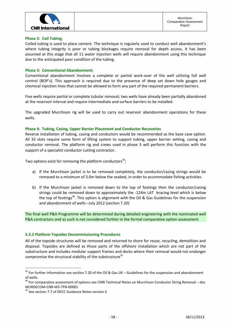
MurchisonComparative Assessment
Report
- 58 - 28/11/2013
Phase 2: Coil Tubing;Coiled tubing is used to place cement. The technique is regularly used to conduct well abandonment’swhere tubing integrity is poor or tubing blockages require removal for depth access. It has beenassumed at this stage that all 11 water injection wells will require abandonment using this techniquedue to the anticipated poor condition of the tubing.
Phase 3: Conventional Abandonment;Conventional abandonment involves a complete or partial work-over of the well utilising full wellcontrol (BOP’s). This approach is required due to the presence of deep set down hole gauges andchemical injection lines that cannot be allowed to form any part of the required permanent barriers.
Five wells require partial or complete tubular removal; two wells have already been partially abandonedat the reservoir interval and require intermediate and surface barriers to be installed.
The upgraded Murchison rig will be used to carry out reservoir abandonment operations for thesewells.
Phase 4: Tubing, Casing, Upper Barrier Placement and Conductor RecoveriesReverse installation of tubing, casing and conductors would be recommended as the base case option.All 33 slots require some form of lifting system to support tubing, upper barrier setting, casing andconductor removal. The platform rig and crews used in phase 3 will perform this function with thesupport of a specialist conductor cutting contractor.
Two options exist for removing the platform conductors45;
a) If the Murchison jacket is to be removed completely, the conductor/casing strings would beremoved to a minimum of 3.0m below the seabed, in order to accommodate fishing activities.
b) If the Murchison jacket is removed down to the top of footings then the conductor/casingstrings could be removed down to approximately the -124m LAT bracing level which is belowthe top of footings46. This option is alignment with the Oil & Gas Guidelines for the suspensionand abandonment of wells –July 2012 (section 7.20)
The final well P&A Programme will be determined during detailed engineering with the nominated wellP&A contractors and as such is not considered further in the formal comparative option assessment.
3.3.2 Platform Topsides Decommissioning ProceduresAll of the topside structures will be removed and returned to shore for reuse, recycling, demolition anddisposal. Topsides are defined as those parts of the offshore installation which are not part of thesubstructure and includes modular support frames and decks where their removal would not endangercompromise the structural stability of the substructure47
45 For further information see section 7.20 of the Oil & Gas UK – Guidelines for the suspension and abandonmentof wells.46 For comparative assessment of options see CNRI Technical Notes on Murchison Conductor String Removal – docMURDECOM-CNR-WS-TFN-0000147 See section 7.7 of DECC Guidance Notes version 6
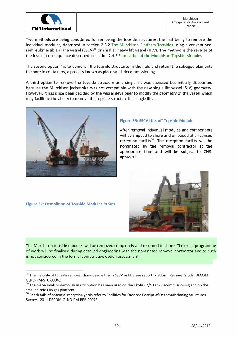
MurchisonComparative Assessment
Report
- 59 - 28/11/2013
Two methods are being considered for removing the topside structures, the first being to remove theindividual modules, described in section 2.3.2 The Murchison Platform Topsides using a conventionalsemi-submersible crane vessel (SSCV)48 or smaller heavy lift vessel (HLV). The method is the reverse ofthe installation sequence described in section 2.4.2 Fabrication of the Murchison Topside Modules
The second option49 is to demolish the topside structures in the field and return the salvaged elementsto shore in containers, a process known as piece small decommissioning.
A third option to remove the topside structure as a single lift was assessed but initially discountedbecause the Murchison jacket size was not compatible with the new single lift vessel (SLV) geometry.However, it has since been decided by the vessel developer to modify the geometry of the vessel whichmay facilitate the ability to remove the topside structure in a single lift.
Figure 36: SSCV Lifts off Topside Module
After removal individual modules and componentswill be shipped to shore and unloaded at a licensedreception facility50. The reception facility will benominated by the removal contractor at theappropriate time and will be subject to CNRIapproval.
Figure 37: Demolition of Topside Modules In Situ
The Murchison topside modules will be removed completely and returned to shore. The exact programmeof work will be finalised during detailed engineering with the nominated removal contractor and as suchis not considered in the formal comparative option assessment.
48 The majority of topside removals have used either a SSCV or HLV see report `Platform Removal Study’ DECOM-GLND-PM-STU-0004249 The piece-small or demolish in situ option has been used on the Ekofisk 2/4 Tank decommissioning and on thesmaller Inde Kilo gas platform50 For details of potential reception yards refer to Facilities for Onshore Receipt of Decommissioning StructuresSurvey - 2011 DECOM-GLND-PM-REP-00043

MurchisonComparative Assessment
Report
- 60 - 28/11/2013
3.3.3 Platform Jacket Decommissioning OptionsOSPAR Decision 98/3 prohibits the dumping and leaving wholly or partly in place of disused offshore
installations.
OSPAR recognises there may be difficulties in removing the footings of large steel jackets weighing over10,000te and installed prior to 9th February 1999. As a result there is a facility for derogation from themain rule for such installations.
The Murchison jacket qualifies for consideration of derogation from OSPAR Decision 98/3 because thejacket weighs 27,584te and it was installed in 1979.51
The presumption of total removal is the starting point for the comparative assessment (CA) process.52
By way of derogation a CA process has to be undertaken in accordance with OSPAR Annex 2 thatrequires there to be significant reasons why a partial removal option is preferable to full removal for re-use, recycling or disposal on land.
Two jacket decommissioning options were identified as being compliant with the OSPAR Decision 98/3and DECC Guidelines and thereby assessed within a formal CA process (see section 4 of this report):
1. Full removal, with foundation piles cut 3m below the mudline. The total weight of jacketremoved would be approximately 27,580te
2. Partial removal of the jacket down to the top of footings, defined as the top of the highestpile53. The total weight of jacket removed would be approximately 14,850te.
The two options are illustrated overleaf.
51 It was intended in OSPAR that jackets installed after 1999 were to be designed to be fully removed regardless ofweight52 See section 7.10 of DECC Guidance Notes version 653 See section 7.11 DECC Guidance Notes version 6

MurchisonComparative Assessment
Report
- 61 - 28/11/2013
Sea Level
Piles cut 3 m below seabed
Sea Level
Piles are cut usinginternal cutting tool
run inside piles
Figure 38: Option 1 -Murchison Jacket Full removal
Drill cuttings
Jacket cut at -112m below LAT,being the highest
pile level
Jacket Piles
Drill cuttings
Jacket cut at -112m below LAT,being the highest
pile level
Jacket Piles
Figure 39: Option 2 - Murchison Jacket Partial Removed

MurchisonComparative Assessment
Report
- 62 - 28/11/2013
3.3.3.1 Jacket Footings Life Expectancy
If the jacket footings are left in place the most significant degradation mechanism will be long termcorrosion. After decommissioning the Murchison topsides and removing the top section of jacket theremaining sacrificial anodes will deplete eventually offering no protection and allowing the remainingstructure to corrode freely. Once the structural members have lost sufficient wall thickness they will nolonger be able to support the self-weight loading and the structure will progressively fail, collapsing intothe jacket footprint.
The most important factors which affect the corrosion of metals immersed in unpolluted sea water aredissolved oxygen and temperature. These factors were addressed in a study predicting the lifeexpectancy of the footings left in place, over time.54
Failure of braces starts after100-150 years
Failure of leg sections start after250 years
Failure of horizontal bracesstarts after 500 years
Failure of main legsstarts after 1000 years
Figure 40: Predicted Degradation Rate of Footings
During the stakeholder consultation process, the question was raised as to whether it was feasible toaccelerate the corrosion rate of the remaining structure to mitigate any long term snagging risk tofishing.
Two options were considered. The first entailed installing a cathodic protection (CP) system wherebythe footings acted as the sacrificial anode. This was concluded as being unviable due to the significantamount of anode material required55.
The second option was to utilise the potential impact of microbial induced corrosion (MIC). MIC istypically localised and patchy in distribution, forming under marine growth e.g. barnacles, or underbiofilms, and results in areas of pitting. It was concluded that bacteria tend to be active in warmer
54 Further details on the Jacket degradation rates are given in the Murchison Decommissioning Study –PreliminaryFootings Life Expectancy - report no DECOM-ATK-ST-REP_0008055 Email JEE to CNRI Dec 2012 subject re Corrosion engineering query

MurchisonComparative Assessment
Report
- 63 - 28/11/2013
environments and that a decommissioned structure that is no longer producing heated fluids throughthe sub-sea infrastructure may present a colder environment and perhaps reduced bacterial growth.
Providing predictions for increased corrosion rates resulting from MIC was unlikely to be robust,however, it is likely that MIC could increase the overall corrosion of a subsea structure above thepredicted electrochemical corrosion rates, and that localised pitting may reduce the structural integrityof any structure left on the seabed but the effects may not be significant.56
3.3.3.2 Jacket Densitometers
As described in section 2.4.2, after piling was completed, the piles were connected to the jacket byinjecting grout between the pile and sleeve. The grouting process was monitored using two groutdensitometers fitted to each of 36 pile sleeves. Each densitometer consists of a Caesium 137 source anda detector.57 Each densitometer is housed inside a lead shield which is further housed inside an outersteel container welded to the pile sleeve surface on the sleeve surface closest to the jacket leg in orderto provide protection during jacket launch.
An outline method statement for the removal and recovery of the densitometers using divers,operating within the confined space of the jacket footings, was completed to inform a hazardidentification and risk assessment (HIRA) of the operation58 . A dose assessment was conducted toassess the worst case exposure in the event that the sources leaked to the environment. Theassessment concluded that there is no adverse impact on the general public either through directexposure to a source or through exposure within the food chain should the sources remain in situ 59
Based on the safety risk and dose assessments undertaken, an application has been submitted to SEPAto reclassify the densitometers as irretrievably lost in that the safety risk to divers in attempting torecover the sources from the deep water confined spaces of the jacket footings is significantly greaterthan the environmental risk of leaving the densitometers in place to decay naturally over time.
3.3.3.3 Jacket Decommissioning Methods
Four methods were investigated for removing all or part the Murchison jacket. The four methodsincluded:
a) Using a semi-submersible crane vessel (SSCV) for removing the Murchison jacket in large
sections and individual components
b) Using a heavy lift vessel (HLV) for removing the Murchison jacket in small sections
c) Using a single lift vessel (SLV) to remove the Murchison jacket in a single piece
d) Using buoyancy tank assemblies to refloat the Murchison jacket in a single piece
See Table 9 Heavy Lift Vessel Capability for details of each of the vessels considered in the alternatemethods described above.
56 Internal email re Degradation rates of Jacket footings April 201157 For details see Technical note on Murchison Densitometers MURDECOM-CNR-EN-ETN-0000158 Assessment of Murchison Densitometer Sources HIRA Report MURDECOM-CNR-EN-REP-0000159 Full details in Application for Leaving the Murchison Densitometers in Place MURDECOM-CNR-EN-REP-0002

MurchisonComparative Assessment
Report
- 64 - 28/11/2013
The following section describes the operations involved in each of the decommissioning method thatwere the subject of specialist studies undertaken in support of the CA process.
(a) & (b) Removing the Jacket Using a SSCV or a HLV
Figure 41 shows a jacket being removed using a semi-submersibledual crane vessel (SSCV). The SSCV with a crane capacity of 14,000teis able to remove the jacket in large sections.
Three60 technical studies were undertaken, to assess the feasibilityof full removal and partial removal of the Murchison jacket:
a) Two studies were based on using the 14,000te capacitySSCV’s, removing the jackets in large sections
b) One study was undertaken using a smaller 5,000te capacityHeavy Lift Vessels (HLV) removing the jacket in individualand small sections.
As shown in Figure 42 the jacket members would be cut into sub-assemblies appropriate to the capacityof the lift vessel using a mix of hydraulic cutters or shears, diamond wire cutting (DWC), or abrasivewater jet cutting.61
60 For details see the three reports Saipem 979978/KMUK/Removal 2002; MURDECOM-HMC-ST-PRO-00033 andMURDECOM-SHL-PM-REP-0006761 For an assessment of cutting tools see Technology for Subsea Cutting of Jacket Members DECOM_GLND-ST-REP-00045
Figure 41: Jacket RemovalUsing a Heavy Lift Vessel

MurchisonComparative Assessment
Report
- 65 - 28/11/2013
The larger SSCVs could remove the jacket in sections weighing up to 4,000te, as shown in Figure 42.
The stability of each section as it is cut away from theremaining structure would need to be verified. The morecomplex operation will be the cutting of the pile foundationat each of the four bottle leg assemblies, whilst maintainingthe stability of the remaining structure prior to liftingclear62.
The piles would be cut using internal pile cutters. If thatwere not possible the pile would be cut using externalcutters after excavating beneath the mud mats. This wouldincrease the problems of ensuring the stability of the bottleleg assemblies after cutting piles just prior to lifting clear ofthe seabed.
The smaller HLV with a crane rated for underwater workingof 2,500te would have to lift the jacket in much smallercomponents of up to 2,000te. This would present problemsfor the removal of the final bottle leg assemblies with eachweighing 3,000te.
c) Removing the Jacket Using a SLV
Figure 43 shows a jacket being removed using thenew single lift vessel (SLV) the Pieter Schelte,currently under construction. The single lift vesselhas a jacket lift system capacity of 25,000tewhereas the Murchison jacket has a total liftweight of 26,131te.63
The concept is based on cutting the jacket pilesbelow the mudline, attaching rigging to the top ofjacket and simultaneously lifting and tilting thejacket until it bears on the tilting lifting beamassemblies. The lifting beams are then pulled downonto the deck and the jacket sea fastened for tow
to shore.
Because the Murchison jacket weight exceeds the SLV lift capacity it was concluded that full removal ofthe Murchison jacket was not feasible with the present SLV jacket lift system (JLS) design.64
62 See TN-Murchison Comparative Assessment Post Workshop Actions MURDECOM-CNR-PM-GTN-00210 for moredetails63 Weight assumes drain holes will be drilled in flooded members before removing the jacket64 See updated Murchison Jacket Removal Method Statement MURDECOM-ALS-ST-PRO-00219 – July 2012
Figure 43: Jacket Removal Using a Single LiftVessel
Figure 42: Jacket Removal in LargeSections
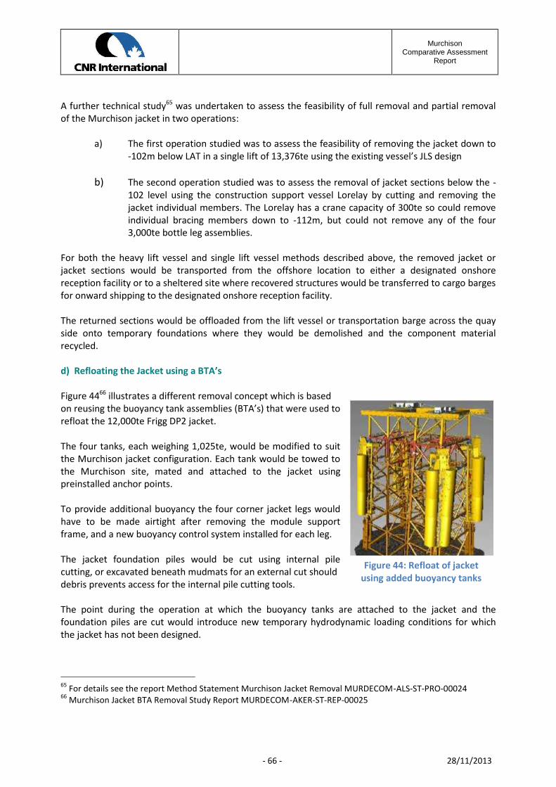
MurchisonComparative Assessment
Report
- 66 - 28/11/2013
A further technical study65 was undertaken to assess the feasibility of full removal and partial removalof the Murchison jacket in two operations:
a) The first operation studied was to assess the feasibility of removing the jacket down to-102m below LAT in a single lift of 13,376te using the existing vessel’s JLS design
b) The second operation studied was to assess the removal of jacket sections below the -102 level using the construction support vessel Lorelay by cutting and removing thejacket individual members. The Lorelay has a crane capacity of 300te so could removeindividual bracing members down to -112m, but could not remove any of the four3,000te bottle leg assemblies.
For both the heavy lift vessel and single lift vessel methods described above, the removed jacket orjacket sections would be transported from the offshore location to either a designated onshorereception facility or to a sheltered site where recovered structures would be transferred to cargo bargesfor onward shipping to the designated onshore reception facility.
The returned sections would be offloaded from the lift vessel or transportation barge across the quayside onto temporary foundations where they would be demolished and the component materialrecycled.
d) Refloating the Jacket using a BTA’s
Figure 4466 illustrates a different removal concept which is basedon reusing the buoyancy tank assemblies (BTA’s) that were used torefloat the 12,000te Frigg DP2 jacket.
The four tanks, each weighing 1,025te, would be modified to suitthe Murchison jacket configuration. Each tank would be towed tothe Murchison site, mated and attached to the jacket usingpreinstalled anchor points.
To provide additional buoyancy the four corner jacket legs wouldhave to be made airtight after removing the module supportframe, and a new buoyancy control system installed for each leg.
The jacket foundation piles would be cut using internal pilecutting, or excavated beneath mudmats for an external cut shoulddebris prevents access for the internal pile cutting tools.
The point during the operation at which the buoyancy tanks are attached to the jacket and thefoundation piles are cut would introduce new temporary hydrodynamic loading conditions for whichthe jacket has not been designed.
65 For details see the report Method Statement Murchison Jacket Removal MURDECOM-ALS-ST-PRO-0002466 Murchison Jacket BTA Removal Study Report MURDECOM-AKER-ST-REP-00025
Figure 44: Refloat of jacketusing added buoyancy tanks

MurchisonComparative Assessment
Report
- 67 - 28/11/2013
The BTAs and corner legs would be deballasted to lift the jacket off the seabed. The ballast controlsystem would run from an attendant vessel rather than the jacket mounted control module used duringits original installation.
Tow lines would be attached and the jacket towed along a deep-water route to a fjord in Norway,where the jacket would be grounded and dismantled in situ using shear leg cranes. A series of towanalysis for both the intact and damaged condition67 would need to be undertaken to verify the jacketstructural integrity would be maintained during the tow.
3.3.4 Murchison Drill Cuttings Management OptionsThe undisturbed Murchison drill cuttings pile is predicted to be significantly below the OSPARthresholds for both total rate of oil release into the water column and persistence over the area ofseabed contaminated. Under these circumstances OSPAR 2005/6 recommends that the bestmanagement option is to leave the pile to degrade naturally.68 69
However some or all of the pile would have to be removed in order to undertake the full removal of thejacket if this option were adopted. Accordingly alternative options for the management of theMurchison drill cuttings pile were assessed in order to understand the implications of having to removethe cuttings pile to facilitate full removal of the jacket structure.
The five options considered were:
a) Leave the cuttings pile in situ to degrade naturally
b) Recover cuttings slurry to surface separate, treat liquids for discharge overboard, ship solids toshore in containers for further treatment and disposal or re-use.
c) Recover cuttings slurry to surface and ship to shore for processing, separation and treatmentand disposal
d) Recover cuttings slurry to surface, grind cutting to a maximum diameter of 300 microns andinject the slurry into a nominated cuttings reinjection (CRI) well
e) Disperse and distribute over the seabed sediments surrounding the Murchison platform.
Two questions relating to the cuttings pile management options were raised by stakeholders during thecomparative assessment process. The first questioned the viability of re-injecting the recovered cuttingsinto a CRI well and the second asked if there was a platform based treatment option that could be analternative to CRI.70
67 Intact and damaged condition analysis are standard floating/tow analysis requirements that model theconsequence of loss of buoyancy in one of the BTA’s or other members providing buoyancy caused by damage orfailure.68 See report Environmental Assessment of Options for the Management of the Murchison Drill Cuttings PileMURDECOM-BMT-EN-STU-0013269 See section 11.0 DECC Guidance Notes version 670 For a full response see Murchison Comparative Assessment – Post Workshop Actions MURDECOM-CNR-PM-GTN-00210
MurchisonComparative Assessment
Report
- 68 - 28/11/2013
For both of these options the first activity would be to recover the cuttings pile from the seabed.71
There is no industry experience of recovering large volumes of drill cuttings from the seabed.72 A test onthe NW Hutton platform recovered 14m3 of drill cuttings to the surface over a 2 day trial period which isnot comparable to the volume of the Murchison pile (22,545m3 )73. It is thus uncertain whether a viablesystem could be developed and tested within the Murchison project timeframe.
A number of problems have been reported74 within closed drilling and CRI systems including:
a) Plugging of CRI wells due to improper slurry rheology and/or inappropriate operatingprocedures
b) Excessive erosion wear from the high volume of reinjection slurry causing well integrity failures
c) Hydraulic fracturing – uncontrolled induced fractures to surface
d) Interaction of new or future well with fractures containing cuttings slurry
e) Local faults/fractures
Because no recovery of drill cuttings from the seabed for re-injection has previously been proposed,there is no legislative framework in place which permits the reinjection of solid and liquid residues fromlifted cuttings and the legislative/compliance requirements have not been tested75. OSPAR is stillconsidering the best way to deal with existing drill cuttings piles. Further it is not clear whether thereinjection of recovered drill cuttings would be classified as waste under the Marine Scotland Act.
There were thus three issues relating to the CRI option that were addressed in the comparativeassessment process, namely:
1. If there is no existing system/process for recovering the large volume of the Murchison drillcuttings pile, could such a system be developed within the project timeframe?
2. Can the CRI technical problems be resolved with certainty?
3. What are the implications for regulatory compliance?
A further question asked if there was a platform-based treatment option that could be an alternative toCRI. In particular could a thermal desorption unit be used76.
71 Further details are given in Murchison Drill Cuttings Pile Removal Methods DECOM-CNR-EN-ETN-0010272 See Oil & Gas UK Cutting Study 2011 for a review of developments in drill cutting recovery equipment since200273 UKOOA 2002 Drill Cuttings JIP Task 6 Drill Cuttings Recovery project. Final Report74 OSPAR Commission 2001 - Environmental Aspects of On-site Injection of Drill Cuttings75 Ref DECC “Offsite injection of drill cuttings “ Guidance for Operators76 See also Oil & Gas UK Cutting Study 2011 which concluded that technologies for the treatment of recovered drillcuttings were not established or proven for offshore use
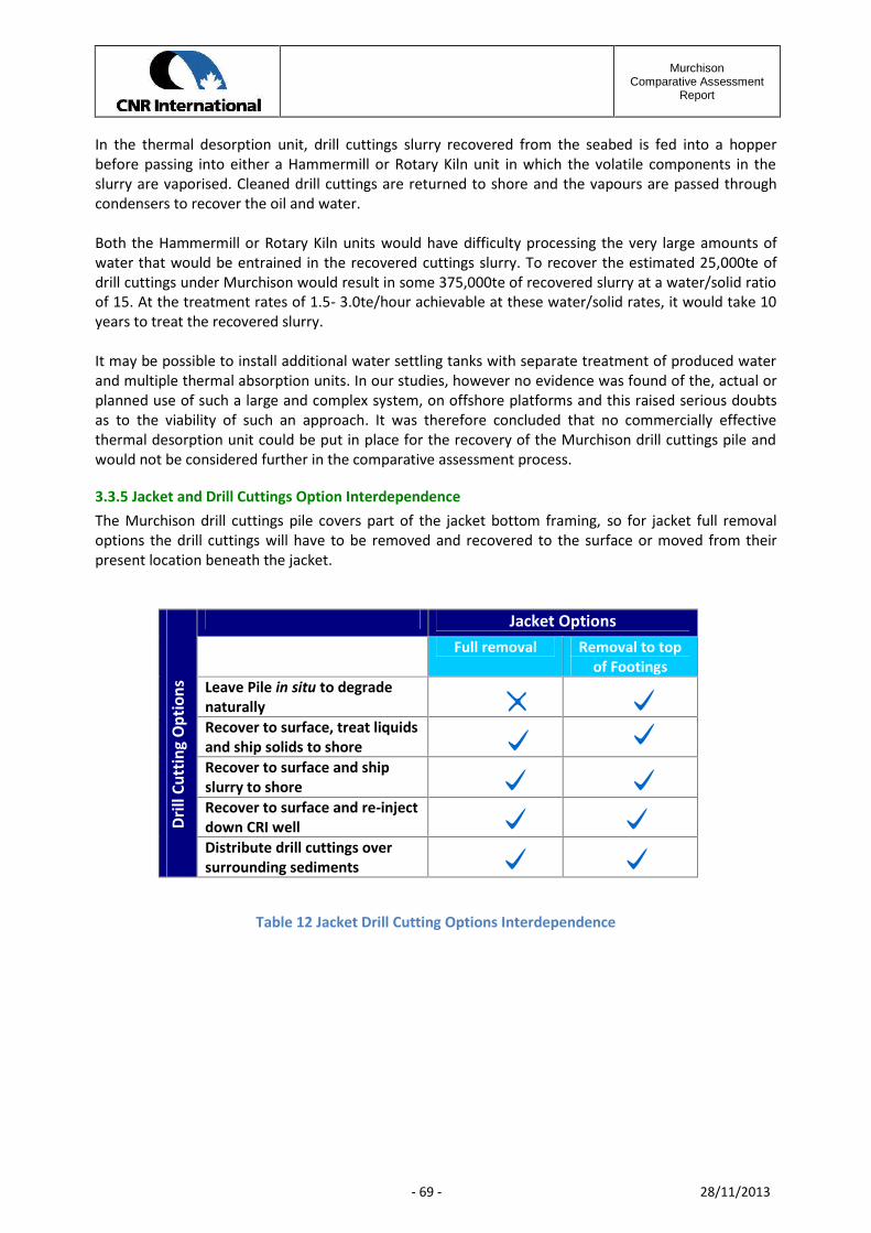
MurchisonComparative Assessment
Report
- 69 - 28/11/2013
In the thermal desorption unit, drill cuttings slurry recovered from the seabed is fed into a hopperbefore passing into either a Hammermill or Rotary Kiln unit in which the volatile components in theslurry are vaporised. Cleaned drill cuttings are returned to shore and the vapours are passed throughcondensers to recover the oil and water.
Both the Hammermill or Rotary Kiln units would have difficulty processing the very large amounts ofwater that would be entrained in the recovered cuttings slurry. To recover the estimated 25,000te ofdrill cuttings under Murchison would result in some 375,000te of recovered slurry at a water/solid ratioof 15. At the treatment rates of 1.5- 3.0te/hour achievable at these water/solid rates, it would take 10years to treat the recovered slurry.
It may be possible to install additional water settling tanks with separate treatment of produced waterand multiple thermal absorption units. In our studies, however no evidence was found of the, actual orplanned use of such a large and complex system, on offshore platforms and this raised serious doubtsas to the viability of such an approach. It was therefore concluded that no commercially effectivethermal desorption unit could be put in place for the recovery of the Murchison drill cuttings pile andwould not be considered further in the comparative assessment process.
3.3.5 Jacket and Drill Cuttings Option InterdependenceThe Murchison drill cuttings pile covers part of the jacket bottom framing, so for jacket full removaloptions the drill cuttings will have to be removed and recovered to the surface or moved from theirpresent location beneath the jacket.
Drill
Cut
ting
Opt
ions
Jacket OptionsFull removal Removal to top
of FootingsLeave Pile in situ to degradenaturallyRecover to surface, treat liquidsand ship solids to shoreRecover to surface and shipslurry to shoreRecover to surface and re-injectdown CRI wellDistribute drill cuttings oversurrounding sediments
Table 12 Jacket Drill Cutting Options Interdependence
MurchisonComparative Assessment
Report
- 70 - 28/11/2013
3.3.6 Export Pipeline PL115 Decommissioning Options
The six options considered for the PL115 pipeline described in section 2.5.2 Murchison Pipeline PL115were:
1. Leave in situ
2. Minimal removal i.e. remove the Murchison and Dunlin tie-in spools only
3. Recover end tie-in spools and exposed sections of the pipeline either by reverse S-lay or by cutand lift
4. Recover end tie-in spools and trench and bury the exposed lengths of pipeline
5. Recover end tie-in spools and place rock over exposed lengths of pipeline to match the existingrock profile
6. Remove the pipeline completely by either reverse S-lay or by cut and lift after displacing theexisting rock cover
(a) & (b) Leave Pipeline In Situ and the Minimal Removal Options
The options (a) and (b) would be the minimum work scopes leaving the pipeline in its existing condition,with only the tie-in spool connections being removed at Dunlin and Murchison for the minimal removal,option (b). It is anticipated that some remedial works may be necessary at the time of decommissioningand in the future where such a need is justified following periodic surveys undertaken to verify thepipeline condition. Over time the exposed sections of the pipeline will deteriorate and break up and thiswill require periodic debris clearance operations to minimise the snagging risk to fishermen.
(c) Remove Exposed Sections of Pipeline by S-Lay or by Cut and Lift
Option (c) is the option to remove the exposed sections of pipeline by S-Lay or by cutting and lifting insections.
The S-lay option was eliminated as impractical because of the large number of short exposed lengthsand the condition of the pipeline. Refer to section 2.5.2 Murchison Pipeline PL115 for details.
The cut and lift option is a proven operational procedure used in pipeline repair where a damagedsection of pipeline is cut, recovered to surface and replaced with a new pipeline section. To remove the17 exposed lengths of PL 115 in 12m long sections would require 746 cuts and the lifting and handlingof 720 x 12m long sections.77
77 The pipeline with concrete weight coat weighs 377kg/m, so a 12m length would weigh approx 4.55 tonnes. 12mis a standard pipe length to suit road transport. Longer section could be lifted depending on the vessel used andcrane capacity, but further cuts would be required to be completed onboard before offloading at an onshorequay.

MurchisonComparative Assessment
Report
- 71 - 28/11/2013
Each section would be cut using hydraulic shears, diamond wire cutting (DWC), abrasive water jetcutting (AWJC) or chop saws as appropriate. To make the cut, using DWC or AWJC cutters, either thepipeline would have to be lifted off the seabed using a deployed lifting frame with hydraulic operatedclamps, or a short trench would have to be excavated to allow the tool access. Cutting excavationtrenches in the very stiff Murchison clays is problematic. In 2006 CNRI took 40 hours to excavate asingle 5.4m long x 2m wide x 800mm deep trench along PL115.78 79 Using the hydraulic shears forcutting does not require lifting or excavation. The location of the cut line from the edge of the rockcover is shown in Figure 45 and will be determined to suit the cutting tool selected.
Cut Line TBC
16" OEL
Varies 0.5 - 1.5m
Figure 45: Location of Cut Lines in PL115
Approximately 2,500 – 3,000 tonnes of new rock placement would be required to cover the pipeline’s34 cut ends in order to provide protection against future fishing snagging. The exact quantity willdepend on the method used to cut the pipeline and the existing rock profile.
(c) Trench and Bury Exposed Sections of Pipeline
On PL115, any trench and burial operation would have to deal with the following two particularproblems:
1. Trenching in the very stiff boulder clays around Murchison would require use of a tool similar tothe Canyon Offshore iTrencher. This cuts a vertical sided trench without generating a spoilsheap which means that once laid in the trench the pipeline would have to be covered byadditional backfill material and or imported rock cover.
2. PL115 has 17 separate exposed sections, each of which would have to be trenched and buried.The exposed sections vary in length from 50m up to 1,900m. On shorter sections there might beproblems attaining the appropriate transition lengths at each end, from the pipe protrudingfrom the rock placement down to placement in the bottom of the trench.
There are seven spans less than 175m long. To accommodate a transition length at the endsplus the exposed section of 2 x 1.5m transition out of the rock profile, three of the spans of lessthan 100m could not accommodate the required transition length and the remaining fourwould have pipe touch down length in trench of less than 50m.
78 For details see Murchison Pipeline Repair Clamp Works- 2006 doc ref MUR-ACE-SUR-REP-0279379 Similar problems were reported by BP for PL 148, where it took 19 hours to excavate a trench to facilitate theabrasive water cutting tool used – see email J Blacklaws to R Sinclair dated 26th July 2012
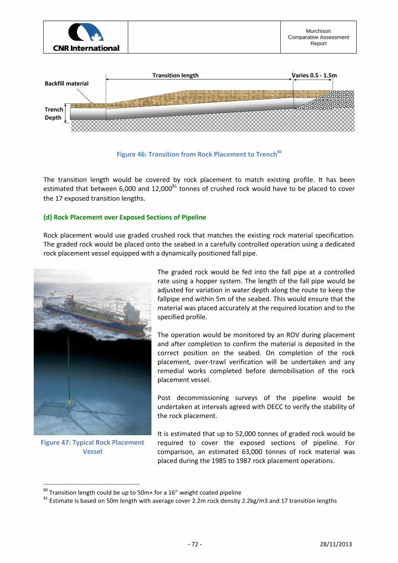
MurchisonComparative Assessment
Report
- 72 - 28/11/2013
Transition lengthBackfill material
TrenchDepth
Varies 0.5 - 1.5m
Figure 46: Transition from Rock Placement to Trench80
The transition length would be covered by rock placement to match existing profile. It has beenestimated that between 6,000 and 12,00081 tonnes of crushed rock would have to be placed to coverthe 17 exposed transition lengths.
(d) Rock Placement over Exposed Sections of Pipeline
Rock placement would use graded crushed rock that matches the existing rock material specification.The graded rock would be placed onto the seabed in a carefully controlled operation using a dedicatedrock placement vessel equipped with a dynamically positioned fall pipe.
The graded rock would be fed into the fall pipe at a controlledrate using a hopper system. The length of the fall pipe would beadjusted for variation in water depth along the route to keep thefallpipe end within 5m of the seabed. This would ensure that thematerial was placed accurately at the required location and to thespecified profile.
The operation would be monitored by an ROV during placementand after completion to confirm the material is deposited in thecorrect position on the seabed. On completion of the rockplacement, over-trawl verification will be undertaken and anyremedial works completed before demobilisation of the rockplacement vessel.
Post decommissioning surveys of the pipeline would beundertaken at intervals agreed with DECC to verify the stability ofthe rock placement.
It is estimated that up to 52,000 tonnes of graded rock would berequired to cover the exposed sections of pipeline. Forcomparison, an estimated 63,000 tonnes of rock material wasplaced during the 1985 to 1987 rock placement operations.
80 Transition length could be up to 50m+ for a 16” weight coated pipeline81 Estimate is based on 50m length with average cover 2.2m rock density 2.2kg/m3 and 17 transition lengths
Figure 47: Typical Rock PlacementVessel

MurchisonComparative Assessment
Report
- 73 - 28/11/2013
The area of the seabed directly impacted by the rock placement would be approximately 8,500m by 5mwhich is equivalent to 0.043km2.
Figure 48: ROV Control of Rock Placement
(f) Total Removal of Pipeline by S-Lay or by Cut and Lift
The S-lay option was eliminated as impractical because of the condition of the pipeline. Refer to section2.5.2 Murchison Pipeline PL115 for details.
For the pipeline total removal option, the existing estimated 63,000 tonnes of crushed rock would haveto be displaced to permit access to the pipeline for cutting. PL115 pipeline runs under the live pipelinesdescribed in Section 1, consequently a length of PL115 must be left in place until the remaining livepipelines are decommissioned. The length of PL115 remaining under the live pipelines will be subject toProximity Agreements82 with each of the respective pipeline owners.
To remove the total pipeline, excluding pipeline cross over corridors, would then require 1600 subseacuts to facilitate the lifting and handling of 1600 x 12m long sections.83
3.3.7 Pipeline Bundles PL123, PL124, PL125 Decommissioning OptionsThe pipeline bundles are as described in section 2.5.1. The carrier pipe has a diameter of 324mm and awall thickness of 6.35mm and weighs 145kg/m. The bundles are neither trenched nor buried.
Initially five decommissioning options were identified for the pipeline bundles:
1. Leave in situ – this was rejected because the bundles were showing signs of damage and wereexpected to further degrade and become an increasing fishing snagging risk
82 For Guidance Note see O&GUK Pipeline Proximity Agreements – 2009. Proximity Agreements will define thework to be done in decommissioning PL115, and conditions attached to that work when working within a specifiedcontrol area of third party live pipelines. The control area has been defined as 300m by the operators of the otherpipelines subject to negotiation83 Pipeline sections are nominally 12m in length. It may be possible to lift double sections of 24m depending onthe condition of the pipeline, the available vessel capacity and the design of the pipe handling frame. This wouldresult in less subsea cuts but more cuts completed on surface.

MurchisonComparative Assessment
Report
- 74 - 28/11/2013
2. Reverse installation – original installation was by submerged depth tow (see2.5.1 MurchisonPipeline Bundles) this was rejected, for removal, due to concerns over the technical feasibilityof bundle and towhead structural integrity
3. Trench and Bury – concerns were expressed over the feasibility of trenching the short bundlelengths in the stiff boulder clays around Murchison. The original ballast chains remain attachedto the bundles and were a further constraint on trenching operations
4. Cover with rock material – remained a viable option
5. Full removal by cut and lift – was a viable option with removal operation considered as part ofthe recovery programme of subsea equipment and protection frames (see 2.6.1 MurchisonSubsea Wells)
The DECC Guidelines suggest that small diameter pipelines, including flexible flowlines and umbilicalswhich are neither trenched nor buried should normally be entirely removed84.
The pipeline bundles PL123, PL124 and PL125 will therefore be removed completely and returned toshore in lengths of approximately 12m, each length weighing 1,740kg.85 Consequently the pipelinebundles were not considered further in the formal comparative assessment process.
3.3.8 Seabed Debris OptionsSub-sea installations include well heads, protective structures, anchor blocks, anchor points and anchorchains used for bundle buoyancy control during installation. All such items will be completely removedfor re-use or recycling or final disposal on land.86 As such subsea equipment and debris will not beconsidered further in the formal comparative assessment process.
A MBES survey of the Murchison 500m zone was undertaken in 2011 and an as-found debris mapproduced (see drg CH-ASA-3956-003). The debris included both oil field related debris and naturallyoccurring boulders and rocks. A further post decommissioning debris survey will be undertaken and aplan for recovery of the oil field debris completed.
3.3.9 Summary of Options Carried Forward to the Comparative AssessmentThe following options were carried forward to the Comparative Assessment Workshop:
For the Murchison Jacket:
1. Full removal of the jacket to 3m below seabed2. Partial removal of jacket down to top of footings at 44m above seabed (EL -112m LAT)
Each option was assessed for each of the removal methods considered, namely:
84 See section 10.8 DECC Guidance Notes version 685 Bundle dry weights 145kg/m86 See section 7.21 DECC Guidance Notes version 6

MurchisonComparative Assessment
Report
- 75 - 28/11/2013
a) Removal using a SSCVb) Removal using a HLVc) Removal using a SLVd) Removal by refloating using BTAs
For the Murchison Drill Cuttings Pile:
1. Leave the drill cuttings pile in situ to degrade naturally2. Recover cuttings slurry to surface separate, treat liquids for discharge overboard, ship solids to
shore in containers for further treatment and disposal or re-use3. Recover cuttings slurry to surface and ship to shore for processing, separation and treatment4. Recover cuttings slurry to surface, grind cutting to a maximum diameter of 300 microns and inject
the slurry into a nominated cuttings reinjection (CRI) well5. Disperse and distribute over the sediments surrounding the Murchison platform.
Combined Jacket and Drill Cuttings Pile Options
1. Full removal of jacket with each of the drill cuttings pile options2. Partial removals of jacket with each of the drill cuttings pile options.
For the Murchison Export Pipeline PL115
1. Leave in situ2. Minimal removal i.e. removal the Murchison and Dunlin tie-in spools only3. Recover end tie-in spools and exposed sections of the pipeline by cut and lift4. Recover end tie-in spools and trench & bury the exposed lengths of pipeline5. Recover end tie-in spools and place rock cover over exposed lengths of pipeline to match the
existing rock profile6. Remove the pipeline completely by cut and lift after displacing the existing rock cover

MurchisonComparative Assessment
Report
- 76 - 28/11/2013
4 The Comparative Assessment Process
4.1 Purpose of the Comparative AssessmentA formal Comparative Assessment (CA) is required under OSPAR Decision 98/3 for facilities which fallwithin any category of structures that may be considered as a candidate for derogation from thegeneral rule of “total removal”; and for pipelines which are candidates for in situ decommissioning asdescribed in the Petroleum Act 1998 and the DECC Guidance Notes.
Screening of the Murchison drill cuttings pile indicates that it falls well below both the OSPAR oil releaserate (10 tonnes/yr.) and area persistence (500 km2 years) and as such would not be subject to a formalstage 2 assessment. However, as the drill cuttings pile must be removed in order to access the jacketfootings CNRI conducted a CA to determine the best option for the drill cuttings pile.
4.2 CNRI CA Method StatementCNRI developed a CA method statement to outline a framework for conducting detailed CA’s for theevaluation of alternative disposal options during the decommissioning planning process. The CNRIframework is based on the high-level framework outlined in the OSPAR Decision 98/3 and the DECCGuidance Notes. It adopts the five main assessment criteria prescribed in these guidelines – Safety,Environment, Technical, Societal and Economic – and appropriate sub-criteria chosen in light of thespecific Murchison facilities and CNRI’s SHE Policy and CNRI’s mission statements.
The CNRI CA methods are covered in detail in the following documents, and are summarised in thischapter:
Comparative Assessment Method Statement DECOM-CNR-PM-PRO-00081 Comparative Assessment Procedure MURDECOM-CNR-PM-PRO-00136
4.3 CA Criteria and ScoringTable 13 details the five main criteria, sub-criteria and the assessment method for each sub-criterion.Sub-criteria were assessed and then scored on a scale of 0-1, where 1 represents the best performanceor outcome, using either quantitative or qualitative measures as described in Table 13.
A series of score guides were developed for the sub-criterion that was assessed on a qualitative basis.These score guides provided a framework for scoring the qualitative measures on a range of 0-1.Qualitative assessments were made by suitably experienced experts and based on the results ofsupporting decommissioning studies.
Quantitative estimates for sub-criteria were based on the data presented supporting decommissioningstudies the values for each option within sub-criteria were transformed onto the 0-1 scale byproportional normalisation of the raw data.
CNRI developed a set of weightings for each of the five main selection criteria, which were subsequentlysplit equally amongst the sub-criteria. The weightings were determined using Analytical HierarchicalProcess (AHP) followed by an internal workshop to discuss the AHP results and ensure the weightingsaligned with CNRI’s SHE Policy, CNRI’s vision and mission statements.

MurchisonComparative Assessment
Report
- 77 - 28/11/2013
The scores for the option in each of the sub-criteria were then multiplied by the weightings that CNRIhas determined for each sub-criterion, and the individual weighted scores summed to give a totalweighted score for each option. The total weighted scores were then examined and discussed todetermine the recommended option for that facility.
A sensitivity analysis was conducted to test whether the results of the Comparative Assessment wouldbe any different if CNRI had selected different weightings. The results of the sensitivity analysisconfirmed that CNRI CA results are robust and would not change with different weightings.

MurchisonComparative Assessment
Report
- 78 - 28/11/2013
Table 13 The Criteria and sub criteria used in the CNRI Comparative Assessments
Criterion Sub-criteria Description of sub-criteria Assessment of sub-criteria
SAFETY
Risk to projectpersonnel offshore Safety risk to project personnel working offshore. Quantitative estimate of total PLL for project personnel.
Risk to projectpersonnel onshore Safety risk to project personnel working onshore. Quantitative estimate of total PLL for project personnel.
Residual risk to otherusers of the sea
The combined safety risk to the crews of commercialfishing vessels, the crews of military vessels and thecrew and passengers of commercial shipping vessels.
87Independent quantitative assessment of the snaggingrisk for commercial fisheries, and consequent risk to lifeand limb, as a result of the option’s end-point. Providesvalues for likelihood of “serious injury” and “fatality”.
ENVIRONMENT
Impacts of operations
The impacts of offshore and nearshore operationson any aspect of the marine environment. Theimpacts of onshore operations (e.g. dismantling,transporting, treating, recycling) on any ecologicalaspect of the terrestrial environment.
Qualitative assessment based on the results of the EIAprocess, where impacts are assessed and the significancecategorised according to a pre-defined Risk AssessmentMatrix.Impacts of end-
points88
The impacts of offshore and nearshore end-pointson any aspect of the marine environment. Theimpacts of onshore end-points (e.g. land filling,secondary use) on any ecological aspect of theterrestrial environment.
Total energyconsumption and CO2
emissions
Total energy consumption (GJ) and CO2 emissions(tonnes).
Quantitative estimate of total energy consumption (GJ)and CO2 emissions (tonnes) that would arise as a result ofthe successful completion of the option, includingtheoretical energy use and gaseous emissions that wouldarise if otherwise recyclable materials were left in thesea. Scores of both measures were averaged to providean overall score for energy and emissions.
87 The other users of the sea in the area of the project will be identified, and the potential for any project end points (e.g. jacket footings, or pipelines left in situ) to interact with otherusers will be identified. Only jacket footings and pipelines are candidates to remain in situ; therefore, it is highly unlikely that there will be any interactions with commercial shippingor the MOD. Consequently, the safety risk to other users of the sea shall be assessed by quantifying safety risk to fishermen.88 End Points addresses the consequence of an operation that describes the final condition of the material or components covered in the option
MurchisonComparative Assessment
Report
- 79 - 28/11/2013
Table 13, continued. The criteria and sub-criteria used in the CNRI Comparative Assessments.
Criterion Sub-criteria Description of sub-criteria Assessment of sub-criteria
TECHNICAL
Technical feasibility Assessment of the technical feasibility of eachoption.
Qualitative assessment by expert judgement which wasbased on the range of engineering and technical studiescarried out by the CNRI decommissioning team and theirindependent consultants.
Ease of recovery fromexcursion
Assessment of the ability to recover fromunplanned excursions and complete the planneddecommissioning option.
Use of proventechnology andequipment
Assessment of the extent to which the optionrequires the use of proven technology.
SOCIETAL
Commercial impact onfisheries
Impacts of both the operations and the end-points on the present commercial fisheries in andaround the Field. (NB Safety risks wereconsidered under “safety” above).
Qualitative assessment based on information in the EIAprocess on the level of fishing activity in the area, the type ofgear used, the value of the fishery, and the value of theground that may or may not be available for fishing oncompletion of the options.
Socio-economicimpacts – amenities
The risks from any near-shore and onshoreoperations and end-points (dismantling,transporting, treating, recycling, land filling) onany aspect of the amenity or infrastructure of theenvironment.
Qualitative assessment based on the results of the EIAprocess, where impacts are assessed and the significancecategorised according to a pre-defined Risk AssessmentMatrix. Also informed by feedback from stakeholderdialogue.
Socio-economicimpacts –communities
The risks from any near-shore and onshoreoperations and end-points (dismantling,transporting, treating, recycling, land filling) onthe health, well-being, standard of living,structure or coherence of communities.
Qualitative assessment based on the results of the EIAprocess, where impacts are assessed and the significancecategorised according to a pre-defined Risk AssessmentMatrix. Also informed by feedback from stakeholderdialogue.
ECONOMIC Total project costThe estimated total CAPEX cost plus a NetPresent Value (NPV) estimate of the cost of anyongoing liability.
Quantitative estimate by CNRI based on the programmesand schedules being prepared for the “Select” phase of theproject.
Comparative AssessmentReport
4.4 CA ProcessCNRI ran a series of specialist workshops (January to May 2012) to assess and score thedecommissioning options within each sub-criteria for the jacket, pipelines and drill cuttings pile.Assessments were made on the basis of relevant study material which was issued as pre-read materialfor each workshop. The workshops were run89 and recorded by an independent chair and secretary andthe discussions and outcomes from the individual workshops were recorded in formal minutes, whichformed the pre-read material for the overall CA workshop.
Results from all of the individual assessment workshops were collated and presented at an overall CAworkshop attended by all project personnel, field equity partners and the IRC (Independent ReviewConsultants).
This workshop, held in May 2012, examined the results and the original raw data behind the weightedscores to:
Review the scores for each of the options Summarise and take into consideration stakeholder’s views Determine if there were any differences in the performance of the different options Determine the extent to which any observed differences in the weighted scores were
significant. Identify and explain the cause(s)of any differences between options Identify the best decommissioning option for each of the facilities under assessment.
A number of actions were identified during the overall workshop in May to validate certain aspects ofthe raw data before a final recommendation could be made. CNRI reconvened two further follow-up CAmeetings in June and July 201290 to review the validated data and to determine the recommendedoptions for decommissioning.
89 Minutes for all the assessment workshops are listed in section 7.8 of this report90 Minutes for the two follow up CA assessment workshops are listed in section 7.8 of this report
Comparative AssessmentReport
- 81 - 28/11/2013
5 – The Comparative Assessment Workshop
This section of the report summarises the main conclusions from the comparative assessmentworkshop held on the 10th May 201291 and follow up meetings with conclusions from sensitivity studiesleading to definition of the preferred option for the Murchison jacket, drill cuttings and pipeline PL115.
The pipeline bundles PL123, PL124 and PL125 and the associated subsea equipment will all becompletely removed and hence are not considered further in the Comparative Assessment process.
5.1 IntroductionThe results and total weighted scores from the individual technical assessment workshops werepresented to the Comparative Assessment (CA) team, including representatives from CNRI’s Murchisonpartners Wintershall and observers from the IRC, at a workshop held on the 10th May 2012.
The workshop considered options for the following facilities
a) Murchison jacket
b) Murchison drill cuttings pile
c) The Interdependence of jacket and drill cutting options
d) Pipeline PL115
The workshop was split into separate sessions in which each facility in turn was described, the possibledecommissioning options summarised and the scores from the relevant technical assessmentworkshops presented and discussed.
Results of a sensitivity analysis of the weightings applied to the total weighted scores, as defined in theCNRI comparative assessment method (DECOM-CNR-PM-PRO-00081) were presented. This analysisindicates the level of robustness of the recommended option by examining how the results would beaffected if the relative importance of the criteria were altered. Following the presentation of thisanalysis a recommended option for the facility was identified.
This section describes the currently recommended option for each facility and the justificationssupporting the recommendation. These justifications are based on the evidence provided by thenumerous technical studies and information provided by the previous technical assessment workshops.Several items of further work identified during the 10th May workshop was completed, reported in PostWorkshop Action Technical Notes (TNs) and considered in reconvened workshops held in June and July2012. The relevant TNs and minutes of the reconvened workshops are listed in section 7.8 of thisreport.
91 For the Workshop minutes of meeting see doc ref MURDECOM-CNR-PM-MOM-0204
Comparative AssessmentReport
- 82 - 28/11/2013
5.2 Murchison Jacket – Results of Comparative AssessmentThe jacket options were
a) Full removal of jacket with foundation piles cut 3m below mudline
b) Partial removal with the jacket removed down to top of footings, with footings left in place.
Each option was considered for the four removal methods described inAs described in section 2.4.2, after piling was completed, the piles were connected to the jacket byinjecting grout between the pile and sleeve. The grouting process was monitored using two groutdensitometers fitted to each of 36 pile sleeves. Each densitometer consists of a Caesium 137 source anda detector. Each densitometer is housed inside a lead shield which is further housed inside an outersteel container welded to the pile sleeve surface on the sleeve surface closest to the jacket leg in orderto provide protection during jacket launch.
An outline method statement for the removal and recovery of the densitometers using divers,operating within the confined space of the jacket footings, was completed to inform a hazardidentification and risk assessment (HIRA) of the operation . A dose assessment was conducted to assessthe worst case exposure in the event that the sources leaked to the environment. The assessmentconcluded that there is no adverse impact on the general public either through direct exposure to asource or through exposure within the food chain should the sources remain in situ
Based on the safety risk and dose assessments undertaken, an application has been submitted to SEPAto reclassify the densitometers as irretrievably lost in that the safety risk to divers in attempting torecover the sources from the deep water confined spaces of the jacket footings is significantly greaterthan the environmental risk of leaving the densitometers in place to decay naturally over time.
Jacket Decommissioning Methods where the four removal methods reflected the spectrum of existingand developing technologies.
The options are ranked for full or partial removal for each of the decommissioning and removalmethods.
5.2.1 Jacket Options scoring for sub criteria
The following option scores were derived by specialist teams independently assessing each criterion.The overall scores were then reviewed by the CA workshop. The sub criteria scores compare the fullremoval and partial removal options utilising each of the four removal methods and are not intended asa comparison between methods.

Comparative AssessmentReport
- 83 - 28/11/2013
Criteria Subcriteria Removal Methods
Full Partial Full Partial Full Partial Full Partial
Safety Personnel offshore 0.3 0.7 0.4 1.0 0.8 0.3 0.5
Personnel onshore 0.3 1.0 0.3 1.0 1.0 0.3 1.0
Fishermen 1.0 0.3 1.0 0.3 0.3 1.0 0.3
Environment Operations 0.7 0.7 0.7 0.8 0.6 0.5 0.6
End points 0.7 0.9 1.0 0.9 0.9 0.8 0.9
Energy 1.0 1.0 1.0 1.0 0.9 0.8 0.8
Emmissions 1.0 1.0 1.0 1.0 0.9 0.7 0.7
Technical FeasibilityTechnical feasibility 0.4 0.8 0.3 0.6 0.0 0.8 0.2 0.3
Recovery 0.7 0.8 0.3 0.4 0.0 0.7 0.2 0.2
Proven technology 0.5 0.9 0.3 0.5 0.0 0.8 0.3 0.6
Societal Fisheries 0.9 0.6 0.9 0.6 0.6 0.9 0.6
Amenities 1.0 1.0 1.0 1.0 1.0 0.8 0.8
Communities 1.0 1.0 1.0 1.0 1.0 1.0 1.0
Cost Capex
Low Worst performance/outcomeMediumHigh Best performance/outcome
SSCV SLV HLV BTA
Table 14 Jacket Options- Sub-criteria Score
The HLV full removal option scored low in all categories because the heavy lift contractor advised thatafter studying the option they concluded it was not feasible with their vessel
5.2.2 Jacket Safety Comparative AssessmentSafety risks were assessed for:
a) Operational risks, being risks to personnel directly involved in the decommissioning andremoval operations
b) Onshore risks, being risks to personnel involved in the fabrication and preparation for offshoredecommissioning operations and in the receipt, demolition and disposal of returned items fromthe offshore operations
c) The residual risk to fishermen arising from fatal snagging incidents related to any jacket remainsleft on the seabed.
Whilst the operational Individual Risk Per Annum (IRPA) for both full and partial removal options areless than the Health and Safety Executive (HSE) tolerable region of 1 in 1000, the full jacket removal hasa PLL of 4.5 x 10⁻² compared to the partial removal option PLL of 2.3 x 10⁻². The full removal option has aPLL 100% greater than that for partial removal This increase in risk was considered as unjustifiable as itgoes against the principal of reducing risks to as low as reasonably practical.

Comparative AssessmentReport
- 84 - 28/11/2013
PLL figures are driven by the number of people involved and the duration of the offshore operations;hence longer operations or those with a greater number of personnel result in higher PLL values andtherefore lower overall scores in this criterion.
The potential risk to onshore personnel consistently had higher PLL values and scored lower for the fullremoval options than the partial removal counterparts, based on the larger amounts of material thatwill be returned to shore for demolition, processing, recycling and disposal.
Partial removal creates a long term and persistent risk to fishermen from the potential snagging of theirfishing gear on the remaining footings. The footings are expected to remain for up to 1000 years. ThePLL for fishermen, directly attributable to the Murchison footings is 1.5 x 10⁻⁵ per annum or 1 in 65,000years.
During the Comparative Assessment workshop a question was raised as to how to combine the shortterm operational risk with the long term residual risk to fishermen.92 The jacket footings will degradeand disintegrate slowly over approximately 1000 years after which the snagging risk to fishermen willdecrease. If the annual risk to fishermen reported to the CA workshop is multiplied by the 1000 yearsand then added to the offshore and onshore operational risk to personnel, the result will represent atotal project risk. It was found that the resulting total project risk for full removal was 16% to 23%higher than for partial removal depending on the removal methods considered. 93
5.2.3 Jacket Environmental Comparative AssessmentEnvironmental impacts associated with the different removal options did not differ significantly suchthat this criterion did not act as a driver between options.
Environmental impacts were considered in terms of operational impacts and long-term end pointimpacts associated with any infrastructure decommissioned in situ. The full jacket removal options werescored slightly higher in terms of environmental impacts of end-points as the entire infrastructure andpotential contaminants would be removed although this was only considered to be of low significance.
The recovery of the footings would also mean that the steel and concrete within the footings could berecycled which is preferable to new manufacture of this material and is reflected in the lower energyand emissions calculated for the full removal option, despite the increased duration and level of vesselactivity. However, the total energy use and atmospheric emissions estimated for all removal optionswere well below the energy emissions arising from one year’s operation of the Murchison platform andwere consequently considered to be of low significance and therefore did not act as a decision driver.
The level of underwater noise created by vessels and cutting operations was found to be similar forboth full and partial removal options. While the duration of the noise would be shorter for the partialremoval options and hence these options were scored slightly higher than the full removal options thiswas not considered to be of significance to act as a decision diver between removal options.
92 For a full response to the question see Technical Note: Murchison Comparative Assessment Post WorkshopActions MURDECOM-CNR-PM-GTN-0021093 The results were reported to a Workshop Follow up session held on the 11th June 2012 ref MURDECOM-CNR-PM-MOM-00203

Comparative AssessmentReport
- 85 - 28/11/2013
It is important to note that the assessment of the environmental impacts of jacket operations and end-points did not consider the potential impacts of having to recover or relocate all or part of the cuttingspile. This is assessed in section 5.3 and the interdependence of jacket and cuttings pile is assessed insection 5.4.
5.2.4 Jacket Technical Comparative AssessmentThe main criterion which separated the full and partial removal options was technical feasibility. Twoissues were raised at the CA and follow-up workshop of 10th May 201294:
a) The technical feasibility of full removal for each method assessed
b) The technical complexity of cutting piled foundations for full removal.
Technical Feasibilitya) Using a conventional semi-submersible crane vessel, (SSCV) full jacket removal is within the
vessel capacity, albeit with the complex issues of cutting free the foundation pile assemblieswhilst maintaining structural integrity.
b) The new single lift vessel (SLV) could not remove the jacket down to mudline in a single lift asthe full weight of the jacket exceeds the capacity of the vessel systems (actual dry weight afterdraining flooded members + marine growth of 26,130te against a capacity of 25,000te). Furtherstudies were undertaken95 to assess the feasibility of changing the operating mode of thevessel, firstly, to separate and remove the top half of the jacket in a single lift and then tochange the jacket lift beams into a shear leg configuration to remove the footings of the jacket.These studies were inconclusive being dependent on the final design of the vessel’s jacket liftbeams and the capacity of the auxiliary blocks, when rated for deep water application, whichhas not currently been determined. Consequently full removal using a SLV was scoredsignificantly lower than that for partial removal.
c) The smaller heavy lift vessels (HLV) cannot remove the footings of the jacket because of craneblock capacity restraints when re-rigged for deep-water operation. The nominal 5000te capacitymain blocks are rated for less than 2,500te when operating in 156m of water. The weight of asingle Murchison bottle leg is in excess of 3,000te and consequently the HLV option scored zerofor the full removal option. Cutting of the bottle legs into smaller sections was not consideredviable.
d) The buoyancy tank assembly (BTA) option would be operating at close to its absolute capacity,and would require the reinstatement of the jacket ballast control system in the four corner legs.The current buoyancy capacity is 23,660te in comparison to the jacket weight of 27,500te whichincludes actual dry weight with flooded members and marine growth. Even with furthermodifications to the existing BTAs the risk of failure for the full removal case was considered tobe unacceptably high and hence full removal scored lower than partial removal.
94 See MOM MURDECOM-CNR-PM-MOM-00204 and Technical MURDECOM=CNR-PM-GTN-0021095 See MURDECOM-ALS-ST-PRO-00024
Comparative AssessmentReport
- 86 - 28/11/2013
Based on the capacities of the removal methods assessed, all four methods are capable of removing theMurchison jacket down to the top of footings but only the SSCV’s method could potentially fully removethe platform with any level of confidence.
The Technical Complexity involved in cutting the Foundation Piles.Full removal of the jacket would require the cutting of the footings below the seabed surface.
This could be achieved with two options:
a) Internal pile cuttingb) External pile cutting
For internal pile cutting any debris inside the pile would have to be removed to allow access for adredging tool to remove the soil plug inside the pile before the cutting tool could be run in. With atleast 6 of the 32 piles known to have substantial internal debris, specialist fishing tools would berequired to remove the debris, before the dredger and cutting tools could be run in.96 The internaldebris consists of scaffold poles, caisson sections, ladders and wire rope. Although the piles are 84 inchdiameter, they are 44m long and hence diver access into piles is not possible97,98.
If the debris from inside the piles could not be removed, or the soil plug excavated down to 5m99 belowseabed, then external cutting would be required. This would involve the excavation of a large volume ofstiff seabed sediment to gain access to the footings. Tools exist in the industry to excavate largevolumes of seabed sediment, but they have not been fully tested for large volumes of the type of stiff,boulder-strewn sediment found at Murchison.
Based on currently available excavation techniques, if this operation were possible, it is likely to be alengthy operation. If excavation is successful the jacket piles would then need to be severed: cuttingtechnologies again exist but do not have a consistent track record for successfully cutting pile groupswith restricted access. Both the excavation and cutting tools would represent proven technology beingused in a new way and as such would require extensive engineering and testing to prove.
Based on the capacities of the equipment and vessels currently available, full removal of the jacketfootings would require multiple cutting and lift operations, the heaviest components being the fourbottle leg assemblies each weighing in excess of 3,000te. The feasibility of the excavation, cutting andlifting operations has not been proved and is likely to require significant engineering developmentbefore work could commence.
Cutting free the bottle legs from the connecting plan bracing and cutting the foundation piles belowmudline introduces stability problems which would be exacerbated if excavation under the mud mats isrequired.
96 Removing debris from pile internals was a problem encountered on the Hutton foundation pile removal,internal cutting of piles was changed to external cutting (personal communication S Etherson to project team)97 See industry Diver Excursion Limit Tables98 See Excursion Tables in Saturation Diving – HSE- Research Report 4499 Soil plug is removed to -5m below seabed to allow cutting tool to be run into the pile to make a cut at -3mbelow seabed

Comparative AssessmentReport
- 87 - 28/11/2013
The partial removal options, which leave the jacket footings in situ, score higher than the full removaloptions for two reasons, firstly because the concerns detailed above do not exist or are present to amuch smaller degree, and secondly, partial removal of comparable jacket structures has beensuccessfully completed before.
The partial removal option does not carry the same concerns as the full removal options about thefeasibility of the excavation, and the cutting and lifting capacity of existing equipment and vessels andtherefore is considered to be more technically feasible with a higher probability of success.
5.2.5 Jacket Societal Comparative AssessmentSocietal considerations were not found to be a great differentiator between options.
There was considered to be a limited impact to onshore amenities and communities because recovereditems would be returned to existing specialist onshore facilities for processing under the necessarymanagement and control procedures. The one exception was the BTA option where the refloated jacketwould be towed to, and grounded at, a near-shore location in a Norwegian fjord for final demolition.This was considered to impact the amenity value of the local area, albeit to a low level and for atemporary duration.
The societal impact on fishing was assessed both for loss of access in the partial removal case and theloss of fishing time due to snagged or damaged nets. As a consequence full removal scored higher thanpartial removal in this case.
5.2.6 Jacket Economic Comparative AssessmentCosts were assessed for both full and partial removal of the Murchison jacket. Costs included the directoperational costs for each option and the long term residual costs arising from future survey andremedial work commitments, discounted to today’s money.
The full removal options cost approximately 75% more than the partial removal options, the cost driverbeing the increased schedule for the full removal options. The one exception was the refloat optionwhere the cost difference between full and partial removal was not significant.
5.2.7 Stakeholder Concerns on Jacket Removal Options.Stakeholder concerns as raised in the March 2012 Stakeholder Workshop100 facilitated by theEnvironmental Council, were largely addressed within the CA Societal and Environmental technicalworkshops101.
One issue raised by stakeholders was that cost should not be a main driver in selecting adecommissioning option. This is the reason for reporting the option rankings both with and withoutcosts included.
5.2.8 Recommended option for Decommissioning the Murchison Jacket
100 See CA Stakeholder Workshop – Transcript Report (March 2012) ref doc MURDECOM-TEC-PM-REP-00184101 See doc ref MURDECOM-CNR-PM-MOM-00179 and MURDECOM-CNR-PM-MOM-00185

Comparative AssessmentReport
- 88 - 28/11/2013
The overall recommended option for the Murchison jacket was determined to be partial removal of thestructure down to the top of footings at 44m above seabed (EL-112m LAT).
It was found that the main drivers for this conclusion were the safety and technical feasibility criteria.
The option ranking was determined by applying criteria weightings to the sub-criteria scores reported inTable 15 and discussed during the CA workshop.
Rank Including cost criteria Rank Excluding cost criteria2 Full Removal SSCV 2 Full Removal SSCV1 Partial removal SSCV 1 Partial removal SSCV2 Full Removal SLV 2 Full Removal SLV1 Partial Removal SLV 1 Partial Removal SLVNA102 Full removal HLV NA Full removal HLV1 Partial Removal HLV 1 Partial Removal HLV1 Full removal BTA 2 Full removal BTA1 Partial removal BTA 1 Partial removal BTA
Table 15: Ranked Decommissioning Options for the Murchison Jacket103
5.2.9 Jacket Sensitivity Analysis of Options’ Performance
A sensitivity analysis was run in which the individual comparative assessment weightings wererandomly varied to check whether CNRI’s weighting of assessment criteria was a significant factor indetermining the option rankings. The results showed that for 99% of possible weightings, partialremoval of the jacket would be the recommended option, though the method of partial removal, e.g.by a heavy lift vessel, or a single lift vessel may change.
5.3 Murchison drill cuttings pile – Results of Comparative AssessmentFive options were assessed for the drill cuttings pile
a) Leave the pile in situ to degrade naturally
b) Distribute the pile onto the adjacent seabed, beyond the jacket footprint
c) Recover the drill cuttings to surface and inject down a designated well
d) Recover the drill cuttings to surface and ship to shore for separation treatment and disposal
e) Recover the drill cuttings to surface, separate treat and dispose of liquids and ship solids toshore for treatment and disposal
102 The small crane vessel (SCV) has a 5,000te capacity block which is de-rated to 2,500te for underwateroperations. A single jacket bottle leg assembly weighs 3,000te which is greater than the SCV capacity.103 Abbreviations SLV = single lift vessel, HLV = Heavy lift vessel, SCV = small crane vessel and BTA = buoyancy tankassembly for re-floating the jacket

Comparative AssessmentReport
- 89 - 28/11/2013
5.3.1 Drill Cuttings Pile sub criteria scores
The following option scores were derived by specialist teams independently assessing each criterion.The overall scores were then reviewed by the CA workshop.
Criteria Subcriteria Decommissioning Options
Safety Personnel offshore 0.8 0.4 0.4 0.2 0.6
Personnel onshore 1.0 0.4 0.4 1.0 1.0
Fishermen 1.0 1.0 1.0 1.0 1.0
Environment Operations 1.0 0.6 0.6 0.6 0.2
End points 0.9 0.9 0.9 0.9 0.6
Energy 1.0 0.9 0.9 0.9 0.9
Emmissions 1.0 0.9 0.9 0.9 0.9
Technical FeasibilityTechnical feasibility 1.0 0.2 0.3 0.4 0.7
Recovery 1.0 0.5 0.5 0.7 0.8
Proven technology 1.0 0.2 0.3 0.8 1.0
Societal Fisheries 0.6 0.8 0.8 0.9 0.8
Amenities 1.0 0.9 0.8 1.0 1.0
Communities 1.0 0.9 0.9 1.0 1.0
Cost Capex 1.0 0.3 0.3 0.3 0.7
Low Worst performance/outcomeMediumHigh Best performance/outcome
Distribute oversurroundingsediments
Treat liquidsoffshore + solids
onshoreLeave Insitu Recover liquids
& solids to shoreRecover to surface
and inject slurry
Table 16 Drill Cuttings Pile - Sub-criteria Scores
5.3.2 Drill Cuttings Safety Comparative AssessmentIn terms of safety, those options which involve the least amount of offshore work e.g. leaving the pile insitu or the ROV-based redistribution of the cuttings across the seabed were scored higher than thosewhich would require a greater number of offshore personnel or longer time to complete the offshoreoperations. The PLL figures for the recovery to surface options were 100% greater than the leave in-situoption.
5.3.3 Drill Cuttings Environmental Comparative AssessmentThe Murchison drill cuttings pile was assessed to fall below the OSPAR thresholds for stage 1 screening.
All management options were considered to have an environmental impact associated with disturbingthe cuttings pile sediments, either directly as a result of the removal method or indirectly as a result ofthe eventual collapse of the jacket footings onto the pile if left in situ. However, disturbance byremoval methods was considered to have a more significant impact than the disturbance of the drillcuttings pile by the collapse of the jacket footings if both the footings and the drill cuttings pile were left

Comparative AssessmentReport
- 90 - 28/11/2013
in situ, as the impacts associated with the collapse would be within already contaminated sedimentsand of a similar magnitude to currently permitted discharges and predicted recovery within 20 years
The distribution of the cuttings across the seabed for the pile redistribution option scored particularlylow under this criterion due to the potential contamination of uncontaminated seabed sedimentsacross a wide area and the long duration of persistence of the impact with recovery predicted within 40years.
It was noted that the cuttings distribution option has been used for other projects, though severedifficulties were encountered such that the time to complete the operation was significantly longerthan estimated. These projects also redistributed a smaller volume of water based mud cuttingsmaterial compared to the larger volumes of oil based mud’s that currently exists at Murchison.
5.3.4 Drill Cuttings Technical Comparative AssessmentThe technical feasibility of both the leave in situ option and the redistribution of cuttings option scoredhighly as a result of high technical feasibility and use of proven technology for the redistribution option.
All the other options require the drill cuttings pile to be recovered from the seabed to the surface fortreatment, reinjection or store and return to shore for treatment. There is no industry experience ofrecovering volumes of the size of Murchison and hence these options scored low on technical feasibilityand development of available technology.104
The offshore reinjection of the cuttings into existing Murchison wells is feasible as this operation iscarried out in some fields during drilling operations; however, the two wells which could be used fordisposal of the cuttings material cannot be fully tested until production from the field has ceased.Further, current offshore reinjection of cuttings is a proven operation for much smaller volumes ofmaterial than the estimated 375,000m3 of cuttings slurry that would be produced from recovering theMurchison cuttings pile. There are concerns that the reinjection of this volume of material may fracturethe Murchison reservoir resulting in very real environmental and safety hazards, such as cratersdeveloping in the seabed surface or well integrity being compromised. Although a second well would beidentified for cuttings injection as a redundancy, the loss of integrity of the primary well may requirethe abandonment of this operation all together.
The options that require the recovery and either onshore or offshore separation, cleaning and disposalof the cuttings solids and waste liquid were scored the lowest of all options. This is because the volumeof material to be recovered from the seabed and brought to shore under either option would besignificantly greater than any volumes which are currently brought onshore for treatment and disposale.g. from drilling operations. In addition, the characteristics of the recovered drill cuttings material maybe sufficiently different from drill cuttings produced during drilling operations to require significantalteration to the processing technology. If required, this bespoke process could be viewed as newtechnology and require significant engineering to complete and prove the system. The technology tocomplete these operations and the onshore facilities to store and process this volume of material donot currently exist.
104 See studies cited in Oil & Gas Cuttings Study 2011

Comparative AssessmentReport
- 91 - 28/11/2013
5.3.5 Drill Cuttings Societal Comparative AssessmentSocietal criteria were not found to be a significant differentiator between the options.
The option to leave the drill cuttings pile in situ scored lower than remaining options because of thepotential loss of fishing grounds, albeit a very small area of 0.007km2 (see section 2.6.2) compared tothe 3,000km2 area of ICES rectangle 51F1.
Amenity and community scores were lower for those options which involved large volumes of materialbeing transported back to shore for treatment.
5.3.6 Drill Cuttings Cost Comparative AssessmentThere is a very significant difference in the cost of leaving the drill cuttings pile in situ to degradenaturally compared with all the other options. The main reasons for the difference are the longdurations and the extensive equipment spreads required, in all options, to recover the drill cuttingsfrom the seabed and return to surface for treatment or re-injection.
5.3.7 Stakeholder Concerns on Drill Cutting management OptionsStakeholders expressed competing concerns between achieving a clean seabed to minimise risks tofishermen and avoid any long term contamination and the environmental disturbance and possiblecontamination during the recovery and removal from the seabed.
Stakeholders acknowledged that CNRI had used the best available technologies to conduct the samplingof the drill cutting pile but there remained some concern that the material deep within the 15m deeppile had not been characterised. CNRI reported105 to the 11th June CA workshop the results of furtherreviews or methods that could be used to obtain deep core samples from the pile which could provideinformation for the long term management of the cuttings pile.
CNRI initially reviewed the option for sampling during the conductor recovery stage and concluded thatthere would be some level of disturbance to the pile during pulling of conductors, the result of whichwould compromise the integrity of any samples subsequently taken, even if practically possible.
CNRI then looked at alternate means of sampling from the platform. Firstly using the original 24 inchdiameter drill cuttings chute over which a compact drilling unit would be mounted on the top deck anda drill corer run through the full depth of the cutting pile. The drill cutting chutes are ideally locatedwith respect to the cutting pile centre but are offset in the vertical making it difficult to run a corerdown the chute. Other caisson positions were checked but rejected because of their offset from thecutting pile centre.
A final option was examined, that being to use the diving stations located on the cellar deck. Of the fivediving stations, stations 3 and 4 could be suitable for accessing the cuttings pile. The operation wouldrequire modifications to the cellar deck, installing temporary steel and plated supports for a dieselhydraulic skid mounted drilling rig that would run the drill corer. A similar unit was used on theMurchison platform to mill out and pull in the NLGP umbilical riser.
105 See MURDECOM-CNR-PM-MOM-00203 and MURDECOM-CNR-PM-GTN-00210

Comparative AssessmentReport
- 92 - 28/11/2013
CNRI concluded that even if sampling of the drill cuttings pile through the diving hatches could beachieved, the results were unlikely to change the ranking of the drill cuttings pile management options.The sampling results might however, help validate the modelling tool used to predict the long term fateof the cuttings material and disturbance effects.
5.3.8 Recommended Option for Decommissioning the Murchison Drill Cuttings Pile
The option identified as the recommended option for the drill cuttings pile is to leave it in situ todegrade naturally.
This is on the basis of the differences in the weighted scores for the safety, environmental and technicalfeasibility criteria.
The option ranking was determined by applying criteria weightings to the sub-criteria scores reported inTable 16 and discussed during the CA workshop.
Rank Including cost criteria Rank Excluding cost criteria1 Leave pile in situ 1 Leave pile in situ2 Distribute offshore 2 Distribute offshore3 Offshore injection 3 Offshore injection4 Onshore separation and
disposal4 Onshore separation and
disposal5 Offshore separation and
liquid disposal; onshoredisposal of solids
5 Offshore separation andliquid disposal; onshoredisposal of solids
Table 17: Ranked Decommissioning Options for the Murchison Drill Cuttings Pile
5.3.9 Sensitivity analysis of options’ performanceSensitivity analysis of the effect of changing the weighting percentages for the criteria showed that forthe range of random combinations assessed, there was a 100% probability that the leave in situ optionwould be the recommended option for the drill cuttings pile.
5.4 Combined Jacket and Drill Cuttings PileThe possible decommissioning options for the Murchison jacket and drill cuttings pile have beenassessed separately on the individual merits and disadvantages of the options.
As the drill cuttings are located directly below and around the jacket and footings, the possiblecombined impacts of disturbing the drill cuttings pile to access or fully remove the jacket has also beenconsidered.
For drill cuttings, when the leave in situ option is discounted the best performing option is toredistribute over the adjacent seabed. The weighted score for this option was then combined with the

Comparative AssessmentReport
- 93 - 28/11/2013
weighted scores for each of the jacket options to determine if the inclusion of cuttings pileconsiderations would have any effect on the ranking of the jacket options. The results are shown inTable 18.
The inclusion of the drill cuttings scores supports the recommended option for partial removal of thejacket and increases the difference between the full and partial jacket removal total weighted scores.
The combined recommendation is therefore for partial removal of the Murchison jacket, allowing thecuttings pile to remain in situ to degrade naturally.
Table 18: Combined Ranked Decommissioning Options for the Murchison Jacket and Drill Cuttings Pile
Rank Including cost criteria Rank Excluding cost criteria1 Partial removal of jacket;
drill cuttings left in situ1 Partial removal of jacket;
drill cuttings left in situ2 Full removal of jacket; drill
cuttings redistributedoffshore
2 Full removal of jacket; drillcuttings redistributedoffshore
5.5 Murchison Pipeline PL115 Results of Comparative Assessment
Six options were considered for decommissioning the PL115 pipeline:
a) Leave the pipeline in situ, intermittently exposed on the seabed and with existing rock coverb) Minimal removal – remove Dunlin and Murchison tie-in spools, leave the remainder in situc) Partial removal of the exposed lengths by cut and liftd) Trench and bury the exposed lengthse) Remedial rock placement over the exposed lengthsf) Total removal of the pipeline by cut and lift after dispersing existing rock cover
5.5.1 PL115 sub criteria scores
The following option scores were derived by specialist teams independently assessing each criterion.The overall scores were then reviewed by the CA workshop.
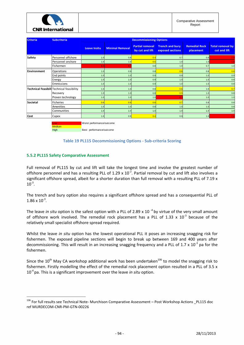
Comparative AssessmentReport
- 94 - 28/11/2013
Criteria Subcriteria Decommissioning Options
Safety Personnel offshore 1.0 0.8 0.4 0.7 0.8 0.3
Personnel onshore 1.0 1.0 0.5 1.0 1.0 0.3
Fishermen 0.3 0.3 0.8 1.0 0.7 1.0
Environment Operations 1.0 0.9 0.8 0.6 0.8 0.6
End points 1.0 1.0 0.9 0.9 1.0 0.9
Energy 1.0 1.0 0.9 1.0 1.0 0.8
Emmissions 1.0 1.0 0.9 1.0 1.0 0.8
Technical FeasibilityTechnical feasibility 1.0 1.0 0.8 0.6 1.0 0.7
Recovery 1.0 1.0 0.8 0.5 1.0 0.8
Proven technology 1.0 1.0 1.0 0.3 1.0 1.0
Societal Fisheries 0.6 0.6 0.6 0.7 0.8 0.8
Amenities 1.0 1.0 0.8 1.0 1.0 0.8
Communities 1.0 1.0 1.0 1.0 1.0 1.0
Cost Capex 1.0 0.9 0.4 0.9 1.0 0.3
Low Worst performance/outcomeMediumHigh Best performance/outcome
Total removal bycut and lift
Remedial Rockplacement
Minimal RemovalLeave Insitu Partial removalby cut and lift
Trench and buryexposed sections
Table 19 PL115 Decommissioning Options - Sub-criteria Scoring
5.5.2 PL115 Safety Comparative Assessment
Full removal of PL115 by cut and lift will take the longest time and involve the greatest number ofoffshore personnel and has a resulting PLL of 1.29 x 10⁻². Partial removal by cut and lift also involves asignificant offshore spread, albeit for a shorter duration than full removal with a resulting PLL of 7.19 x10⁻³.
The trench and bury option also requires a significant offshore spread and has a consequential PLL of1.86 x 10-3.
The leave in situ option is the safest option with a PLL of 2.89 x 10 -4 by virtue of the very small amountof offshore work involved. The remedial rock placement has a PLL of 1.33 x 10⁻³ because of therelatively small specialist offshore spread required.
Whilst the leave in situ option has the lowest operational PLL it poses an increasing snagging risk forfishermen. The exposed pipeline sections will begin to break up between 169 and 400 years afterdecommissioning. This will result in an increasing snagging frequency and a PLL of 1.7 x 10⁻³ pa for thefishermen.
Since the 10th May CA workshop additional work has been undertaken106 to model the snagging risk tofishermen. Firstly modelling the effect of the remedial rock placement option resulted in a PLL of 3.5 x10⁻⁴ pa. This is a significant improvement over the leave in situ option.
106 For full results see Technical Note- Murchison Comparative Assessment – Post Workshop Actions _PL115 docref MURDECOM-CNR-PM-GTN-00226

Comparative AssessmentReport
- 95 - 28/11/2013
A second post partial removal model was generated. This assumed that the existing exposed sections ofpipeline had been removed by cut and lift and the resulting exposed cut ends protected by a rock cover.This left a series of separate rock covered berms for which a fishing risk of 3.3 x 10⁻⁴ pa was calculated.
Rock has already been used to protect some sections of the pipeline and historical surveys demonstratethat this rock has remained stable and over-trawlable by fishing gear. The use of rock to cover theremaining exposed section would reduce the risk of snagging fishing gear and is also, in terms ofoffshore operations, the option with the lowest risk to offshore personnel.
When comparing the partial removal by cut and lift with the remedial rock placement over exposedsections, the former has an operation PLL five times greater than the later, for no reduction in theresidual snagging risk to fishermen i.e. for fishing risk partial removal has a fishing PL or 3.3 x 10⁻⁴
compared to 3.5 x 10⁻⁴ for remedial rock placement.
5.5.3 PL115 Environmental Comparative AssessmentWhen considering environmental impacts, the trench and bury option was found to have the greatestimpact on the seabed and the longest recovery time due to the amount of disturbance to the sedimentsto ensure the exposed sections were buried to a minimum depth of 0.6m.
The total removal of the pipeline would require some excavation of the sediments in order to positionsome types of cutting equipment. The existing rock cover would have to be removed from the pipelineto provide access for cutting and lifting of the pipeline. The existing rock cover would most likely bemoved using a form of mass flow jetting tool which would scatter the rock across the adjacent seabed.The long-term impact of this scattered rock would not be significant as the Murchison sediments areknown to be strewn with surface and sub-surface rocks and boulders.
In terms of risk to fishing activities, this natural condition of the seabed would usually require the useof hard-bottom or rock-hopping demersal gear and so the scattered rock material would be unlikely torequire a change of the type of gear used in the area.
The partial removal option would have less of an impact on the seabed sediments than total removal,as any disturbance associated with excavation of the sediment to position the cutting gear would beconfined to a smaller area and would not be related to the relocated existing rock cover, though the cutends would have to be buried or covered with rock.
Extending the rock-placement to cover the exposed sections would physically disturb the seabed butthe level of disturbance would be less than for the trenching option. Rock placement would utilise anROV controlled fall pipe equipped with cameras, profilers and other sensors to ensure rock is onlyplaced within the planned footprint with minimal spread over adjacent sediment, thereby minimisingseabed disturbance.
The remedial rock placement option would also replace some of the existing soft sediment with anadditional modified hard substrate. Surveys around the Murchison platform show that the seabedexhibits areas of cobbles and boulders with small amounts of gravel with shell debris. The presence ofthis naturally occurring hard substrate together with the existing rock placement material suggests thatorganisms associated with hard substrates will already be present in the area and will not be introducedas a result of any new rock placed within the area. The area of modified substrate would be kept to a
Comparative AssessmentReport
- 96 - 28/11/2013
minimum by the accurate placement and profiling of rock. There are no Annex 1 habitats along theroute of PL115.
As no operations would be undertaken for the leave in situ option there would be little impact to theenvironment: the long-term degradation of the pipeline was considered and the impact of any releasedcontaminants is expected to be of low significance because the line would have been flushed andcleaned before decommissioning. The concrete coating of this pipeline would also prevent significantmovement of the pipeline across the seabed as it degrades.
5.5.4 PL115 Technical Comparative AssessmentThe use of rock placement and the recovery of spool-pieces from pipelines are all standard operationswithin the oil and gas industry.
The total removal and partial removal options for the pipeline by cut and lift are also standardoperations though these are more complex when dealing with aging concrete-coated pipelines.
As with the excavation of the jacket footings, there are some concerns over the ability of currenttrenching equipment to successfully and efficiently complete the operation in sediments which are stiffand contain numerous boulders as at Murchison. Further, some of the exposed sections are too short todeploy the equipment and accommodate the necessary trench transitions of the equipment – thesesections would have to be buried by rock cover. For this reason the feasibility of the trench and buryoption for the PL115 pipeline is in question and was scored low.
5.5.5 PL115 Societal Comparative AssessmentAll options scored similarly for the amenities and communities sub-criteria. The effects of processing ofany returned material were not considered to be significantly higher than those resulting from normaloperations.
Differences in the options were primarily driven by the impact on commercial fisheries particularlyrelated to loss of access for those options in which exposed sections of the pipeline would be left on theseabed.
5.5.6 PL115 Cost Comparative AssessmentCosts were assessed for all six PL115 decommissioning options. Costs included the direct operationalcosts for each option together with the long term residual costs arising from future survey and remedialwork commitments, discounted to today’s money.
The options total removal, and partial removal, both by cut and lift, scored considerably lower than theremaining options because of the difference in the length of the operations involved.

Comparative AssessmentReport
- 97 - 28/11/2013
5.5.7 PL115 Stakeholder ConcernsStakeholder concerns as raised in the March Stakeholder Workshop107 facilitated by the EnvironmentalCouncil were largely addressed within the CA Sociatel and Environmental technical workshops108.
One issue raised by stakeholders was that cost should not be a main driver in selectingdecommissioning options. This is the reason for reporting the options ranking with and without costsincluded.
Stakeholder concerns were primarily with safety risks associated with the pipeline or sections of thepipeline remaining in situ. Follow up sessions were held separately with the SFF and JNCC during whichconcerns were raised relating to the change in habitat for the PL115 remedial rock placement optionand the risk to fishermen of the rock placement option compared to the cut and lift options.109
5.5.8 Recommended Option for Decommissioning the Murchison Pipeline PL115The oil export pipeline PL115 is 19km long and is constructed of steel with concrete weight coating.Approximately 11km of the pipeline is covered by graded rock, leaving 17 uncovered sections varyingfrom 1.96km to 50m in length.
Two options were identified as comparable options based on the overall weighted scores: leave in situand remedial rock placement with the latter scoring marginally higher overall based on the lower riskto fishermen. These scores were driven by safety and technical feasibility concerns.
The option ranking was determined by applying criteria weightings to the sub-criteria scores reported inTable 19 and discussed during the CA workshop.
Rank Including cost criteria Rank Excluding cost criteria1 Remedial rock placement 1 Remedial rock placement2 Leave in situ 2 Leave in situ3 Trench and bury 3 Trench and bury4 Minimal removal 4 Minimal removal5 Total removal 5 Total removal6 Partial removal 6 Partial removal
Table 20: Ranked decommissioning options for the pipeline PL115
5.5.9 PL115 Sensitivity analysis of options’ performanceThe sensitivity analysis of the overall weighted scores for the decommissioning options for PL115indicated that the leave in situ option and rock placement options would always be ranked as the toptwo options despite any changes to the weighting percentages.
107 See CA Stakeholder Workshop – Transcript Report (March 2012) ref doc MURDECOM-TEC-PM-REP-00184108 See doc ref MURDECOM-CNR-PM-MOM-00170 and MURDECOM-CNR-PM-MOM-00185109 These concerns were further studied and the results reported in the PL115- Post Workshop ActionsMURDECOM-CNR-PM-GTN-00226

Comparative AssessmentReport
- 98 - 28/11/2013
There is also an 82% probability that leave in situ would be the recommended option. However, whenstakeholder concerns and CNRI core values are considered, the leave in situ option, which does notinclude any immediate action to mitigate future risks to the fishing industry from the presence of thepipeline, is unacceptable.
The recommended option for the PL115 pipeline is therefore to extend the present rock cover over theexposed sections.
Comparative AssessmentReport
- 99 - 28/11/2013
6 Independent Review Consultants – Verification Certificate
The requirement for independent verification of the comparative assessment process is defined inDECC’s Decommissioning Guidelines.
The DECC Decommissioning Guidelines define the purpose of such verification being to confirm that thedata used is sound and appropriate, the assessment reliable, the comparative assessment processtransparent and the chosen decommissioning option supported by credible and verifiable data.
CNRI appointed Xodus Group Ltd (Xodus) as the expert Independent Review Consultant (IRC) toundertake the verification process in support of the Murchison Decommissioning Programme.
The specific role of the IRC was to ensure that an appropriate range of decommissioning options wasbeing assessed in sufficient depth and quality so that the resultant information available was adequatefor a rational decision to be reached by CNRI in the Comparative Assessment Process (CA).
This was achieved by ensuring that the IRC maintained an independence from CNRI’s ComparativeAssessment decision making process. The verification process then included
1. Review and comment on the studies and technical reports used to inform the CA process
2. Review and comment on the CNRI’s Comparative Assessment Method Statement
3. Attend the pre-assessment workshop to witness the briefing of the CA participants
4. Review the Minutes of Meeting from the pre-assessment workshop and technical scoring
meetings
5. Review Minutes of Meeting and notes of individual stakeholder meetings.
6. Attend stakeholder open session to witness the briefing and handling of questions from
stakeholders
7. Review the Minutes of Meeting notes, finding and conclusions from the CA workshop
8. Review the means by which the results from the CA workshop are reported back to
stakeholders
At the conclusion of the CA process, the IRC provided its report, published alongside this document insupport of the Decommissioning Programme, summarizing their findings for individual studies used insupport of the CA and a separate statement on the process that CNRI employed to manage thecomparative assessment process. See Murchison Decommissioning Comparative Assessment – FinalIRC Report MURDECOM-XDS_PM-REP-00062.
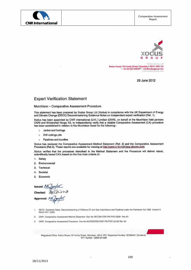
Comparative AssessmentReport
- 100 -28/11/2013
Comparative AssessmentReport
- 101 -28/11/2013
7 Reference DocumentsThis section of the report list all reference documents, studies and regulatory procedures referred to inthe Comparative Assessment process.
7.1 Regulations and Procedures
DECC Guidance Notes Version 6
OSPAR 2006. Recommendation 2006/5 on a Management Regime of Offshore Cuttings Piles
Oil & Gas UK Guidelines for the Suspension & Abandonment of Wells – Issue 4 2012
Comparative Assessment Method StatementDECOM-CNR-PM-PRO-00081
Comparative Assessment ProcedureMURDECOM-CNR-PM-PRO-00136
Murchison Decommissioning Comparative Assessment – Final IRC ReportMURDECOM-XDS-PM-REP-00062
7.2 SurveysMurchison Pre-Decommissioning Environmental Baseline SurveyMURDECOM – ERT-EN-REP-00056
ISS Pipeline Inspection and Jacket Survey 2011PLS-ISS-SU-REP-15430
Murchison Asset Inventory Study ReportMURDECOM-PSN-PM-REP-00037
Murchison Platform – 2010 ROV Structural Inspection ReportMUR-ISS-SU-REP-15406
Murchison Shipping Traffic SurveyMURDECOM-ATC-EN-STU-00199
CNRI Assets- Topside Structural Integrity Surveys 2011MUR-ATK-ST-REP-0227
Murchison Field – Subsea Inspection of 16” oil export line, flowlines and wellheads – 1983(Report by Sub Sea Survey Ltd- CNR075646)
Soils Survey Report – 1977Fugro- U0170-2/1

Comparative AssessmentReport
- 102 -28/11/2013
Facilities for Onshore Receipt of Decommissioning Structures Survey -2011DECOM-GLND-PM-REP-00043
Refurbishment /Demolition Asbestos Survey – Murchison Platform April 2012-09-26MURDECOM-RPS-EN-REP-00200
CNRI Technical Note on Murchison Subsea Satellite Well StatusMURDECOM-CNR-PM-WTN-00001
7.3 Removal StudiesMurchison –Post CoP Alternate Use AppraisalDECOM-GLND-PM-STU-00048
Murchison Platform Removal Technology StudyDECOM-GLND-PM-STU-00042
Murchison Jacket Weight ReportMURDECOM-ATK-ST-REP-00253 revA2 July 2012
Murchison Topside Weight ReviewMURDECOM-ATK-ST-REP-00010
Murchison Jacket Weight CalculationsMURDECOM-ATK-ST-REP-00254
Murchison Field 2002 Decommissioning StudySaipem Doc 979978/KMUK/Removal 2002-CNR096810
Murchison Topside & Jacket Removal Study-Method StatementMURDECOM-HMC-ST-PRO- 00033
Method Statement Murchison Jacket RemovalMURDECOM-ALS-ST-PRO- 00024
Murchison Jacket Removal Method StatementMURDECOM-ALS-ST-PRO-00219 – July 2012
Provision of Topside and Jacket Removal Studies decommissioning of the Murchison PlatformMURDECOM-SHL-PM-REP- 00067
Murchison Jacket BTA Removal Study ReportMURDECOM-AKER-ST-REP- 00025
CNRI Technical Note on Murchison Anchor Pile CuttingMURDECOM-CNR-PM-GTN-00137
Evaluation of Removal Options for the Murchison JacketMURDECOM-GLND-PM-REP-00008
Comparative AssessmentReport
- 103 -28/11/2013
Murchison Platform Structural Analysis Model DevelopmentMUR-ATK-ST-REP-0157
Limitation to Marine Operations during Platform RemovalDECOM-GLND-MA-REP-00044
Technology for Subsea Cutting of Jacket membersDECOM-GLND-ST-REP-00045
Murchison Topside Separation Study ReportMURDECOM-PSN-ST-REP-00043
Technical Notes on Murchison DensitometersMURDECOM-CNR-EN-ETN-00001
PL115-16” Oil Export Pipeline, Lifetime Expectancy StudyCNR32-r01c
Ninian North and Murchison Preliminary Footings Life AssessmentDECOM-ATK-ST-REP-00080
CNRI Technical Note on Murchison Conductor String RemovalMURDECOM-CNR-WS-TFN-00001
7.4 Drill CuttingsCNRI Technical Note on Murchison Drill Cuttings Pile Removal MethodsDECOM-CNR-EN-ETN-00102
Murchison Drill Cuttings Pile – Environmental Impact StudyMURDECOM-BMT-EN-STU- 00132
Murchison Drill Cuttings Pile Long-Term Cuttings Pile CharacteristicsMURDECOM-GEN-EN-REP- 00133
Murchison Drill Cuttings Pile Modelling the Effects of Human Disturbance of the Cuttings PileMURDECOM-GEN-EN-REP- 00135
Oil & Gas UK Cutting Study 2011MURDECOM-FSS-PM-STU-00001
7.5 EnvironmentEnvironmental Statement for the Decommissioning of the Murchison FacilitiesMURDECOM-BMT-EN-REP-00198
Underwater Noise Impact Assessment for the Murchison Field DecommissioningMURDECOM-BMT-EN-REP- 00122

Comparative AssessmentReport
- 104 -28/11/2013
Energy and Emissions Report for the Decommissioning of MurchisonMURDECOM-BMT-EN-REP- 00125
Environmental Statement for the Decommissioning of the Murchison Facilities – RiskAssessment and Environmental Assessment Workshop ReportMURDECOM-BMT-EN-REP- 00127
Murchison Decommissioning - Commercial Fisheries - Socioeconomic Impact StudyMURDECOM-SFF-EN-STU- 00131
Evaluation of the Extent of Colonisation of Lophilia pertusa and Marine Growth on theMurchison PlatformA.INS.001/Murchison 2010-CNR0105209
Assessment of Marine Growth levels on MurchisonNNP-ATK-ST-TEC-0140
Environmental Conditions in the Northern North Sea – Marex report(no document number)
Wave Characteristics ModelDECOM-PHYSE-EN-STU-00063
Metocean Criteria for MurchisonPhyse Ltd document reference C319-R413-10
Application for Assessing the Removal of the Murchison DensitometersMURDECOM-CNR-EN-REP-0002
7.6 PipelineMurchison Subsea and Pipeline Assets – Decommissioning ReportMURDECOM ATK-PI-REP- 00027
Murchison Subsea and Pipeline Assets RegisterMURDECOM ATK-PI-DAB- 00028
2011 Pipeline Inspection & Environmental Survey Phase 2 Report…PLS-ISS-SU-REP-15430
Subsea Ultrasonic Inspection of selected areas on the 16” Murchison Oil export pipelineC42666/01 Issue 01MUR-ACE-SU-REP-02796
Technical Integrity Assessment 2010 – North Sea PipelinesCNR0106254
Final Inline Inspection Report – PL115 -2010CNR080046
Comparative AssessmentReport
- 105 -28/11/2013
PL115-16” Oil Export Pipeline Lifetime Expectancy StudyMURDECOM-JEE-PM-STU-00233
7.7 SafetyDecommissioning Project - General Hazid Jacket Removal ReportDECOM-WHF-SA-HAZ-00094
Decommissioning Project - Major Hazard Workshop Identification Report - Woodhill FrontierDECOM-WHF-SA-REP-00106
Murchison Platform - Perpetuity Liability Hazid - Hazid ReportMURDECOM-WHF-SA-HAZ- 00103
Decommissioning Project – Safety Support – Murchison Topsides and Jacket DecommissioningHazid - Heerema OptionMURDECOM-WHF-SA-REP- 00071
Decommissioning Project – Safety Support – Murchison Jacket Decommissioning Hazid - AkerMarine OptionMURDECOM-WHF-SA-REP- 00074
Decommissioning Project – Safety Support – Murchison Topsides and JacketDecommissioning Hazid - Allseas OptionMURDECOM-WHF-SA-REP- 00076
Decommissioning Project – Safety Support – Murchison Pipeline Decommissioning Hazid -Atkins OptionMURDECOM-WHF-SA-REP- 00080
Decommissioning Project – Safety Support - Murchison - Topsides and JacketDecommissioning Hazid - SHL OptionMURDECOM-WHF-SA-REP- 00087
Decommissioning Project – Safety Support – Murchison Onshore Disposal - Hazid/Envid ReportMURDECOM-WHF-SA-REP- 00113
Decommissioning Project - QRA Report - Murchison Jacket Decommissioning Options –Woodhill FrontierMURDECOM-WHF-SA-REP- 00115
Decommissioning Project- QRA Report – Murchison Pipeline Decommissioning OptionMURDECOM- WHF-SA-REP-00089
Decommissioning Project- QRA Report – Murchison Topsides Decommissioning OptionsMURDECOM-WHF-SA-REP-00114

Comparative AssessmentReport
- 106 -28/11/2013
Decommissioning Project – Safety Support – Murchison Topsides Decommissioning Hazid -AFDO Marine OptionMURDECOM-WHF-SA-REP- 00072
Decommissioning Project – Murchison Platform – Murchison Pipelines and Platform Fishing RiskAnalysis - Technical NoteDECOM-ATC-EN-TN-00098
Murchison Decommissioning Study – Preliminary Footings Life AssessmentDECOM-ATK-ST-REP-00080
Ship Collision Risk – Management ReviewA1204-CNR-TN-1
Assessment of Murchison Densitometer Sources HIRAMURDECOM-CNR-EN-REP-00001
7.8 Comparative Assessment & Stakeholder WorkshopsCA Workshop – Pre-Assessment Introduction WorkshopMURDECOM-CNR-PM-MOM- 00151
CA Workshop – Technical Assessment Murchison JacketMURDECOM-CNR-PM-MOM- 00156
CA Workshop – Economic Assessment Murchison Jacket & PipelinesMURDECOM-CNR-PM-MOM- 00161
CA Workshop – Technical Assessment Murchison PipelinesMURDECOM-CNR-PM-MOM- 00162
CA Workshop – Safety Assessment Murchison Jacket & PipelinesMURDECOM-CNR-PM-MOM- 00176
CA Workshop – Societal Assessment Murchison Jacket & PipelinesMURDECOM-CNR-PM-MOM- 00179
CA Stakeholder Workshop – Transcript Report (March 2012)MURDECOM-TEC-PM-REP-00184
CA Workshop – Environmental Assessment Murchison Jacket & PipelinesMURDECOM-CNR-PM-MOM- 00185
CA Workshop – Drill Cuttings Pile AssessmentMURDECOM-CNR-PM-MOM- 00186
CA Workshop – Murchison 10th May 2012MURDECOM-CNR-PM-MOM- 00204

Comparative AssessmentReport
- 107 -28/11/2013
CA Workshop – Follow up Murchison Workshop 11th June 2012MURDECOM-CNR-PM-MOM- 00203
Technical Note – Murchison Comparative Assessment – Post Workshop ActionMURDECOM-CNR-PM-GTN-00210
Technical Note- Murchison Comparative Assessment – Post Workshop Action – PL115MURDECOM-CNR-PM-GTN-00226
Murchison Decommissioning Stakeholder Workshop 8th Nov 2012 – Summary ReportMURDECOM – CNR-PM-REP-00236
Murchison Decommissioning Stakeholder Workshop 8th Nov 2012 – Transcript ReportMURDECOM – CNR-PM-REP-00237