on ground beam forming and multi user …proceedings.kaconf.org/papers/2014/ka14_5.pdf · on ground...
TRANSCRIPT

ON GROUND BEAM FORMING AND MULTI USER DETECTION: HARDWARE DEMONSTRATOR TEST RESULTS AND TECHNOLOGY
ROADMAP
Claudio Campa ([email protected]), Eugenio Rossini, Aldo Masci, Paolo Altamura, Filippo Di Cecca,
Space Engineering S.p.A., Via dei Berio 91, 00155-Rome, Italy (Tel. +39 06 22595232)
Rosalba Suffritti ([email protected]), Elisabetta Primo, Mavigex S.r.l., Strada Maggiore 63, 40125 – Bologna, Italy (Tel. +39 051 199 821 70)
F. Vanin ([email protected]), S. Cioni,
ESA-ESTEC, Keplerlaan 1, 2201 AZ Noordwijk, The Netherlands (Tel. +31 71 565 6829)
Jerome Tronc ([email protected]) EADS Astrium SAS, av. des Cosmonautes 31, 402 Toulouse Cedex 4, France
(Tel. + 33 5 62 19 69 70)
Abstract In the frame of the ARTES-5.1 ESA project “On Ground Beam Forming Networks and Multi User Detection Proof of Concept” Space Engineering, Mavigex and Astrium defined different scenarios of interest for the On Ground Beamforming (OGBF) with Multi user detection (MUD), based on a single S-Band GEO satellite with an European service area. The project also foresaw the realization a hardware demonstrator implementing a scaled version of an OGBF/MUD system [3] in order to verify the achievable performance, to be compared with the numerical simulations presented in [2]. The recent strong interest in OGBF [1][2] is motivated by multiple reasons. First, the need for higher capacity systems has pushed for the development of very large antenna reflectors for use in L and S-band mobile satellites. With the increase in the reflector size, an increase in the required number of feeds, for covering a given geographical region, is also experienced and the on-board complexity for digital beamforming (DBF) would thus correspondingly increase. The OGBF would move the DBF complexity to the Gateway. Moreover OGBF has additional advantages with respect to on-board DBF as it allows for more advanced signal processing, including Multi-User Detection (MUD), to be performed at the GW side with significant potential benefits at system level. In particular, for interactive traffic, OGBF would open the possibility to implement optimal dynamic beamforming where the antenna pattern is reconfigured on the fly according to the users being served at any given time frame. In this paper the test bed performance achievements will be presented along with the comparison with numerical results for validation purpose. Then the possible improvements in architecture/algorithms/technology will be presented with the aim of simplifying and making efficient the implementation of a large scale system in a commercial scenario.
1. Introduction The hardware OGBF demonstrator presented in [3] (see fig.1) includes the following elements and functionalities:
• Traffic emulator, allowing to emulate the User Terminals traffic (with fully representative air interface) and relevant channel (i.e. taking into account variability in the power among active users) and to distribute the signals with appropriate amplitude and phase relationships to the Satellite Emulator input ports taking into account the direction of arrival of the source signals.
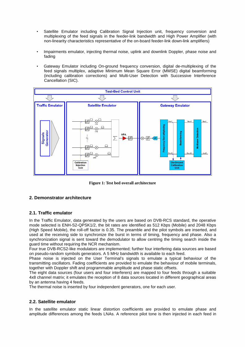
• Satellite Emulator including Calibration Signal Injection unit, frequency conversion and multiplexing of the feed signals in the feeder-link bandwidth and High Power Amplifier (with non-linearity characteristics representative of the on-board feeder-link down-link amplifiers)
• Impairments emulator, injecting thermal noise, uplink and downlink Doppler, phase noise and fading
• Gateway Emulator including On-ground frequency conversion, digital de-multiplexing of the
feed signals multiplex, adaptive Minimum Mean Square Error (MMSE) digital beamforming (including calibration corrections) and Multi-User Detection with Successive Interference Cancellation (SIC).
Figure 1: Test bed overall architecture
2. Demonstrator architecture
2.1. Traffic emulator In the Traffic Emulator, data generated by the users are based on DVB-RCS standard, the operative mode selected is ENH-S2-QPSK1/2, the bit rates are identified as 512 Kbps (Mobile) and 2048 Kbps (High Speed Mobile), the roll-off factor is 0.35. The preamble and the pilot symbols are inserted, and used at the receiving side to synchronize the burst in terms of timing, frequency and phase. Also a synchronization signal is sent toward the demodulator to allow centring the timing search inside the guard time without requiring the NCR mechanism. Four true DVB-RCS2-like modulators are implemented; further four interfering data sources are based on pseudo-random symbols generators. A 5 MHz bandwidth is available to each feed. Phase noise is injected on the User Terminal’s signals to emulate a typical behaviour of the transmitting oscillators. Fading coefficients are provided to emulate the behaviour of mobile terminals, together with Doppler shift and programmable amplitude and phase static offsets. The eight data sources (four users and four interferers) are mapped to four feeds through a suitable 4x8 channel matrix; it emulates the reception of 8 data sources located in different geographical areas by an antenna having 4 feeds. The thermal noise is inserted by four independent generators, one for each user.
2.2. Satellite emulator In the satellite emulator static linear distortion coefficients are provided to emulate phase and amplitude differences among the feeds LNAs. A reference pilot tone is then injected in each feed in

the signal band edge, before up-converting the associated signal. The pilot tone will be used in the gateway to recover the original phase and frequency at the output of each feed, eliminating the frequency errors introduced by the frequency multiplexing/demultiplexing operations and downlink transmission. Phase noise is injected on the Satellite Emulator pilot tones to emulate the on-board oscillators’ typical characteristics. The non-linear HPA distortion is applied to the composite multiplexed signal formed by the four feeds. The OMUX emulator is implemented with a non uniform group delay typical of an analogue RF OMUX.
2.3. Gateway emulator In the Gateway Emulator, the multiplexed signal is processed by four PLL locked to the pilot tones associated the feeds, which are down converted to base band with their original phase and frequency. A dynamic digital beam-forming is then performed exploiting the MMSE Algorithm. The computation of the MMSE matrix requires the estimation of the channel matrix starting from the estimation of the synchronization parameters and of the covariance matrix using payload samples. The multi-user detection is performed by the iterative repetition of the MMSE-SIC algorithm [3]. In each iteration the strongest signal at the beamformer output is demodulated, rebuilt in base band and subtracted to the other signals on the basis of the estimated channel matrix. Acting in this way each feed can be demodulated with its strongest interferers cancelled. The number of iterations is equal to 4, one for each active user.
3. Test campaign An extensive test campaign has been carried out using four scenarios to validate the OGBF demonstrator and to evaluate its performance with respect to theoretical results including the impairment effects. To this purpose each test result of the hardware demonstrator has been compared with the performance evaluated through the PST (Payload Simulation Tool), a software tool developed by Space Engineering in other projects but adapted and completed for the present program. Such tool has been configured to reproduce the OGBF demonstrator, including impairments and satellite and Gateway processor. The tool works in floating point, so it has been exploited not only to validate the demonstrator functionalities, but also to evaluate the losses of the fixed point arithmetic, implicit in the HW implementation, with respect to the floating point processing.
3.1 Test conditions The considered scenarios include a channel matrix with moderate interference level to be used as a reference for static beamforming (excluding the adaptive MMSE SIC), and three channel matrices with increasing interference levels among the four users. The channel matrix for static beamforming presents SNIR (Signal to Noise and Interference Ratio) characteristics indicated in Table 1, with a BF matrix optimized for an S/N working point of 2 dB.
SNIR (at SNR=2dB) User 1 User 2 User 3 User 4 Before static BF -0.81961 -0.38063 0.780375 0.878114 After static BF 1.688514 -0.28455 2.521809 1.098124
Table 1: SNIR characteristics adopted for the static beamforming test
The most critical scenario (whose channel matrix is labeled as ‘B’) is reported in Fig. 2. The main figures for such scenarios are reported in Tab. 1 assuming a noise power N equal to -4 dBW.

Figure 2 Reference simulation scenario for MMSE-SIC (channel matrix ‘B’)
N SNIR SIR N+I SCh 1 -4 dBW -0.87138 dB 1.46692 dB -0.1943 dBW -1.0657 dBWCh 2 -4 dBW -0.08447 dB 2.89936 dB -0.9631 dBW -1.0475 dBWCh 3 -4 dBW 1.89898 dB 4.92914 dB -1.0095 dBW 0.8895 dBWCh 4 -4 dBW -1.76990 dB -0.69159 dB 2.5784 dBW 0.8085 dBW
Table 2: Main figures (S, N+I, SNIR, SIR) for the reference scenario.
Further tests have been carried out using other two channel matrices (generated from a real 8*8 matrix cluster (frequency reuse) out of a 1000 matrix set – the most interfering users from different beams had been selected), with the following characteristics:
Matrix SIR User 1 2 3 4
note
E 4.1522 3.7164 0.1786 3.5583 Medium interference level F 4.5285 0.6155 1.8411 5.0706 Light interference level
Table 3: SIR characteristics of the additional channel matrices for MMSE-SIC
Such additional channel matrices present a smaller level of interference with respect to the baseline matrix ‘B’. The impairments emulated during the tests are summarized in Tab.2
Phase Noise on the UT 1 MHz:95 dBc/Hz; 100KHz: 88dBc/Hz; 10KHz: 74 dBc/Hz; 1KHz: 65 dBc/Hz; 100Hz: 55dBc/Hz
Phase Noise on the Satellite 1 MHz:105 dBc/Hz; 100KHz: 104dBc/Hz; 10KHz: 99 dBc/Hz; 1KHz: 98 dBc/Hz; 100Hz: 88dBc/Hz
Doppler on the UT (U1 = 1500 Hz; U2 = -500 Hz; U3 = 500 Hz; U4 = -1500 Hz)
Doppler on the Satellite 30 Hz
Table 4: Emulated impairments conditions
3.2 Test results The tests with static beamforming showed the performances in Figure 3 with and without impairments. Users 3 and 1 have a smaller interference level and work in the S/N zone where BF matrix is optimized with respect to the noise, while users 4 and 2 need a better SNR. As a consequence users 3 and 1 are more sensitive to the impairments with respect to users 4 and 2, whose largest contribution to their losses is given by the interference of the other beams, only partially recovered by the beamforming. These results has been confirmed by the PST simulations.
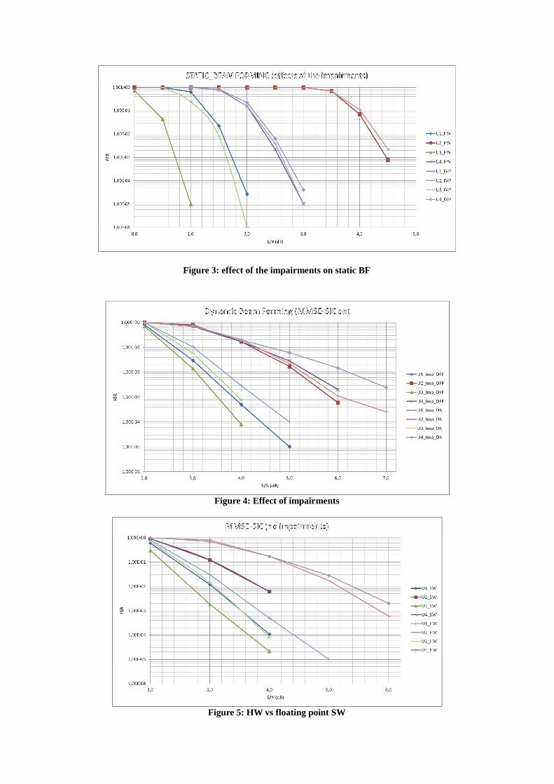
Figure 3: effect of the impairments on static BF
Figure 4: Effect of impairments
Figure 5: HW vs floating point SW

In Figure 4 and Figure 5 the performances of the OGBF demonstrator with MMSE-SIC are shown. In Figure 4 the performances of the HW demonstrator with and without the impairments listed in table are compared. In Figure 5 a comparison of the performance of the HW demonstrator with the floating point PST simulator is given. The tests with the channel matrix ‘E’ and ‘F’ of Table 3 (presenting a smaller level of interference) showed a better matching with the PST software simulator and also smaller loss due to the impairments.
3.3 Result analysis
The tests carried out on the OGBF demonstrator can be summarized in the following test cases: Test Condition HW losses versus PST
(floating point SW) PST losses with impairments
HW losses with impairments
Static beamforming MMSE-SIC excluded, fixed beam forming matrix, channel matrix with very low beams interference (matrix « D »)
0.2 dB
≤ 0.8 dB
≤ 0.8 dB
MMSE-SIC light Channel matrix with low beams interference (matrix « F »)
0.3 – 0.8dB (depending on the beam)
≤ 0.5 dB
≤ 0.5 dB
MMSE-SIC medium Channel matrix with medium beams interference (matrix « E »)
0.3 – 0.8dB (depending on the beam)
≤ 0.8 dB
≤ 0.7 dB
MMSE-SIC hard Channel matrix with hard beams interference (matrix « B »)
0.8 – 1.8 dB (depending on the beam)
≤ 0.8 dB
≤ 1 dB
Table 5: Test cases summary
These results show that:
• Without MMSE-SIC the fixed point losses relative to the demodulator are limited to 0.2 dB, and the impairments effects in the PST and in the HW are equivalent
• With the MMSE-SIC, the losses of the HW with respect to the PST increase and are dependent on the beam. In particular the loss increases with the cancellation iteration, as expected
• The loss of the HW - with respect to the PST - is more sensitive to the channel matrix interference level after a given threshold, after which the fixed point arithmetic of the HW starts to lose more than 1 dB with respect to the PST
This behaviour is justified by the following considerations:
• The most critical section of the OGBF from the arithmetic point of view is the MMSE-SIC engine, because it includes matrices inversions and iterative cancellation with re-estimation operations, where the losses are accumulated. This explains the range of losses among different beams, between PST and HW;
• The criticality discussed in the previous point causes constant losses until a given interference level, beyond which the estimation errors and numerical problems amplified during the iterations introduce significant misalignment of the beamforming matrices with respect to the ideal case, increasing the losses.
4. Efficient implementation of a large scale system in a commercial scenario In Table 6 the main differences between a possible large scale system implementing OGBF and the scaled version of the demonstrator are listed. Several architectural assumptions have been done in order to simplify the large amount of processing tasks, both in the payload and in the gateway. The payload architecture in the return link foresees a digital processor implementing a static beamforming on the 51 feeds, to obtain 26 beams. The main advantage of this approach is the reduction of the requirements of feeder-link bandwidth by the ratio 26/51 (~50%). Such “coarse” beams are frequency multiplexed and transmitted to the gateway together with the pilot tones to recover the frequency offset and variation in the feeder link.
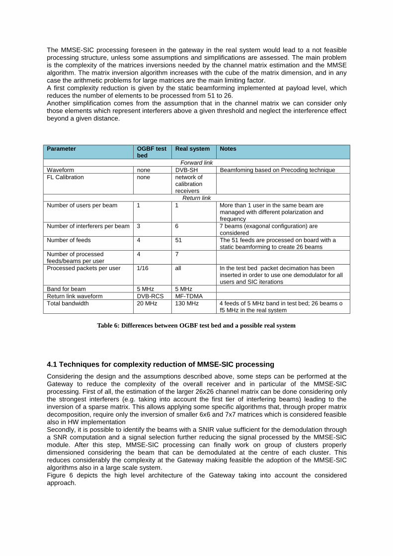
The MMSE-SIC processing foreseen in the gateway in the real system would lead to a not feasible processing structure, unless some assumptions and simplifications are assessed. The main problem is the complexity of the matrices inversions needed by the channel matrix estimation and the MMSE algorithm. The matrix inversion algorithm increases with the cube of the matrix dimension, and in any case the arithmetic problems for large matrices are the main limiting factor. A first complexity reduction is given by the static beamforming implemented at payload level, which reduces the number of elements to be processed from 51 to 26. Another simplification comes from the assumption that in the channel matrix we can consider only those elements which represent interferers above a given threshold and neglect the interference effect beyond a given distance. Parameter OGBF test
bed Real system Notes
Forward link Waveform none DVB-SH Beamfoming based on Precoding technique FL Calibration none network of
calibration receivers
Return link Number of users per beam 1 1 More than 1 user in the same beam are
managed with different polarization and frequency
Number of interferers per beam 3 6 7 beams (exagonal configuration) are considered
Number of feeds 4 51 The 51 feeds are processed on board with a static beamforming to create 26 beams
Number of processed feeds/beams per user
4 7
Processed packets per user 1/16 all In the test bed packet decimation has been inserted in order to use one demodulator for all users and SIC iterations
Band for beam 5 MHz 5 MHz Return link waveform DVB-RCS MF-TDMA Total bandwidth 20 MHz 130 MHz 4 feeds of 5 MHz band in test bed; 26 beams o
f5 MHz in the real system
Table 6: Differences between OGBF test bed and a possible real system
4.1 Techniques for complexity reduction of MMSE-SIC processing Considering the design and the assumptions described above, some steps can be performed at the Gateway to reduce the complexity of the overall receiver and in particular of the MMSE-SIC processing. First of all, the estimation of the larger 26x26 channel matrix can be done considering only the strongest interferers (e.g. taking into account the first tier of interfering beams) leading to the inversion of a sparse matrix. This allows applying some specific algorithms that, through proper matrix decomposition, require only the inversion of smaller 6x6 and 7x7 matrices which is considered feasible also in HW implementation Secondly, it is possible to identify the beams with a SNIR value sufficient for the demodulation through a SNR computation and a signal selection further reducing the signal processed by the MMSE-SIC module. After this step, MMSE-SIC processing can finally work on group of clusters properly dimensioned considering the beam that can be demodulated at the centre of each cluster. This reduces considerably the complexity at the Gateway making feasible the adoption of the MMSE-SIC algorithms also in a large scale system. Figure 6 depicts the high level architecture of the Gateway taking into account the considered approach.

Figure 6: Potential Architecture of the Gateway for large-scale systems
5. Conclusion In this paper the main achievements of the ARTES-5.1 ESA project “On Ground Beam Forming Networks and Multi User Detection Proof of Concept” have been presented. In particular the test results of the hardware demonstrator implementing a scaled version of an OGBF/MUD system have been illustrated. Such results showed that the hardware implementation reflects the floating point software simulator until a certain amount – considerably high - of interference level (exemplified by the channel matrix ‘B’ in the test scenarios), beyond which increasing losses are recorded. Such behaviour is due to the criticality of the MMSE-SIC algorithm, implying matrices inversions and iterative signals reconstructions performed in fixed point. When the interference and noise levels limit the dynamic of the wanted signals too much, the numerical errors in the MMSE-SIC algorithms become not negligible. On the basis of these considerations an architecture for a possible large scale system implementing OGBF has been presented, with some recommended strategies limiting the system complexity, in order to be implemented with available, state of art technology.
References [1] SatNEx III CoO 1 Task 2 “Hybrid Space-Ground Processing”, Technical report of ESA Contract
RFQ/3-12859/09/NL/CLP. [2] F. Di Cecca, G. Gallinaro, E. Tirrò, C. Campa, S. Cioni, P. Angeletti, E.A. Candreva, F.
Lombardo, A. Vanelli-Coralli, “On-Ground Beamforming and Interference Cancellation for next generation mobile systems”, Proc. of AIAA/Ka-band conference 2012, Ottawa (Canada), Sep. 2012
[3] C. Campa, E. Rossini, P. Altamura, A. Masci S. Andrenacci E. Primo, R.Suffritti S. Cioni, P. Angeletti J. Tronc: “On Ground Beam Forming And Multi User Detection Proof Of Concept”, Proc. of AIAA/Ka-band conference 2013, Florence (Italy), Opt.. 2013
[4] M. Karkooti, J. R. Cavallaro, “FPGA Implementation of Matrix Inversion Using QRD-RLS Algorithm”, Conference Record Thirty-Ninth Asilomar Conference on Signals, Systems & Computers, November 2005.
[5] L. Ma, K. Dickson, J. McAllister, J. McCanny, “MSGR-based Low Latency Complex Matrix Inversion Architecture”, ICSP2008 Proceedings, May 2008.