r210806 - riser replace midrise final
TRANSCRIPT
August 6, 2021 1266 Apartment Corp. C/o Mr. Michael Denker First Service Residential 5 Horizon Road Fort Lee, NJ 07024 VIA EMAIL ([email protected]) ONLY RE: 1266 Apartment Corp. - HVAC Riser Observations Y:\Clients\Falcon2013\13-372\Documents\MEP\25-Riser Replace 1,2,3,4\R210806 - Riser Replace
Midrise_Final.Docx
Dear Mr. Denker: As per your request, Falcon Engineering has prepared this summary report to highlight our observations from the development of repair and replacement specifications for the dual temperature HVAC risers at Buildings 1 - 4 at 1266 Apartment Corp. The scope of this work encompasses the primary heating and cooling distribution systems for the residential dwelling units and common areas in Buildings 1, 2, 3 and 4. Various options have been explored for the replacement of the dual temperature HVAC risers at the Horizon House, located in Fort Lee, New Jersey. The options Falcon has evaluated as part of this effort include the following:
1) Replacement of the existing system with a single pipe, TACO Load-Match type system. 2) Replacement of the existing system with a substantially similar configuration utilizing alternate
materials. 3) Replacement of the existing system with modifications to improve quality of life to the Mid-Rise
unit owners.
The draft repair plans and specifications that have been completed to date reflect option #3 which will be outlined in this report.

2
Y:\Clients\Falcon2013\13-372\Documents\MEP\25-Riser Replace 1,2,3,4\R210806 - Riser Replace Midrise_Final.Docx
Background: Horizon House is a six-building cooperatively owned complex with 1,266 dwelling units located at Horizon Road in Fort Lee, NJ. The site includes four (4) “Mid-Rise” buildings (Buildings 1 – 4) and two (2) “High-Rise” buildings (Buildings 5 & 6). Each Mid-Rise building is fifteen (15) stories high with approximately 180 dwelling units each. Each High-Rise building is twenty-nine (29) stories high with approximately 270 dwelling units each.
From a code perspective, all six of the buildings at Horizon House would be classified as High-Rise buildings, but for the purposes of this report and the project at large we will refer to Buildings 5 and 6 as the “High-Rise” buildings, and Buildings 1,2,3, and 4 as the “Mid-Rise” buildings.
Falcon has previously prepared HVAC riser replacement plans for the High-Rise buildings and has been contracted by the Corporation to prepare draft plans and bid documents for the replacement of the HVAC riser piping in the Mid-Rise buildings in anticipation of commencing work on that project at some point following the conclusion of the work in progress at Building 6.
Existing Systems Conditions:
Consistent with our observations at the site over the past 5 years in both the High-Rise and Mid-Rise buildings, we have the following observations.
The Horizon House community was built in phases between 1962 and 1967. The Mid-Rise buildings were primarily built between 1963 and 1965. The age of the majority of the HVAC piping infrastructure is approximately between 56 and 58 years.
Each of the four Mid-Rise buildings has its own standalone HVAC systems, with the majority of the equipment located in mechanical rooms in the cellar levels. Each building provides heating and cooling with central boiler and chiller plants. This equipment was upgraded during a large infrastructure project that took place starting in 2014, providing new high efficiency modular hot water boilers and new electric centrifugal chillers, gas and electric utility infrastructure was upgraded in order to accommodate the new equipment.
Heating and cooling of the residential dwelling units is primarily accomplished via fan coil units connected to a two-pipe dual temperature closed loop system that feeds either hot water or chilled water to the fan coil depending on the season and mode of operation. Seasonal change over from heating to cooling is generally performed in mid-May, and the changeover back to heating is performed around mid-October. The precise dates may vary depending on seasonal weather conditions.
The original HVAC riser piping in all six buildings was constructed of Schedule 40 Steel Piping for the risers, and copper branch lines connecting the risers to the fan coil units. Prior to the replacement of the High-Rise piping, the piping at all six buildings was observed to be in similar condition.
The Corporation has in the past 5 years completed a large-scale central plant upgrade that included both replacement of the central heating plant, a natural gas conversion, and replacement of the existing engine driven absorption chillers to electric centrifugal chillers. The cooling towers for all buildings have been replaced. Pumps serving all distribution systems have been replaced and the replacement pumps have been provided with variable frequency drives to allow modulation of flow in the systems, (with the exception of the Building 6 HVAC pumps which had already been replaced immediately prior to the central plant

3
Y:\Clients\Falcon2013\13-372\Documents\MEP\25-Riser Replace 1,2,3,4\R210806 - Riser Replace Midrise_Final.Docx
upgrade project), and better control/performance. While this major investment was made to improve the reliability and redundancy of the central equipment, the original piping infrastructure in the Mid-Rise buildings remains and is prone to failure.
Specifically, with respect to the Mid-Rise buildings, in addition to the poor condition of the supply and return riser piping, insulation, branch lines, and valves, the condensate drainage system has completely failed. The condensate formed by the fan coils while in the cooling mode of operation should be draining to a third riser pipe located with the supply and return lines. Many of these pipes have been bypassed completely, as a result of this systemic failure which has led and continues to lead to substantial property damage. The condensate drainage system that was originally installed consisted of galvanized steel piping material. This material is known to have issues when exposed to certain chemicals where interior corrosion and build up will close off or occlude the inner diameter of the piping to the point it can no longer keep up with the capacities required to either flow domestic water, or in this case drain away the condensate that forms on the fan coils during cooling operation. At the areas where the original system is bypassed drainage is diverted out to the balconies. This leads to staining of the façade, and damage to the balconies over time. The system as it is currently installed is no longer functional.
The piping was originally installed with insulation wrapped around both the supply and return lines, with a continuous vapor barrier that was designed to serve several purposes. First the insulation prevents heat loss or heat gain to the water that is circulating through the HVAC systems to ensure efficient operation and that the temperatures of the fluid arrives at the fan coil units in accordance with the original design values to provide proper heating and cooling to apartments. The second purpose of this insulation is to prevent moisture or condensation from forming on the outside of the cold piping when the system is operating during the cooling season. The spaces where the piping is located is very close to and in some cases located within the building envelope and may be exposed to humid ambient air temperatures during the summer months. When the system is working properly, the insulation separates the cold pipe from the moisture in the air keeping the surface temperatures above the dew point and preventing condensation.
Over time, the insulation materials break down, are damaged by renovations or other maintenance operations and the vapor barrier becomes compromised. The moisture in the air then comes into contact with the colder piping and forms condensation which can travel through the insulation due to gravity and capillary action of the material. As a result, the entire riser pipe is exposed to the moisture and oxygen from the time the system is changed over from heating to cooling mode, until the heating operations resume, and the insulation dries out. The steel piping begins to corrode, and rust forms, with sections of the piping material delaminating and reducing the effective strength of the piping.
While this occurs the fittings where the branch lines are connected to the risers also become damaged and weaken, which is a major contributing factor in the branch line failures that have occurred in both the Mid-Rise and High-Rise buildings.

4
Y:\Clients\Falcon2013\13-372\Documents\MEP\25-Riser Replace 1,2,3,4\R210806 - Riser Replace Midrise_Final.Docx
Falcon has had the opportunity to evaluate the condition of the piping where it was exposed over the past 5 years. Where riser piping was exposed for renovations ultrasonic testing has was performed.
Pipe HVAC Supply HVAC Return
Material Steel (Sch. 40) Steel (Sch. 40)
Nominal Pipe Size 2-1/2 2-1/2
Nominal Wall Thickness [in] 0.203 0.203
Measured Wall Thickness [in] 0.156 0.200
ASTM Min. Wall Thickness [in] 0.178 0.178
Signal Strength 6 Bars 6 Bars 1: Results of Ultrasonic Testing at one location
The supply piping in particular reveals significant deterioration. From a visual assessment the condition of the piping is uniform throughout the community and there is a reasonable degree of engineering certainty that these results would be repeated throughout the Mid-Rise buildings at the HVAC risers, with the severity of the corrosion increasing from the top of the building down.
Falcon referenced ASTM standard A53 to determine the minimum permissible wall thickness for the pipe. The minimum permissible wall thickness for the 2-1/2-inch pipe is 0.178 inches, with an original specified wall thickness 0.203 inches. The exterior surfaces of the pipes are corroded, leaving layers of stratified rust which does not contribute to the effective wall thickness of the pipe.
5
Y:\Clients\Falcon2013\13-372\Documents\MEP\25-Riser Replace 1,2,3,4\R210806 - Riser Replace Midrise_Final.Docx
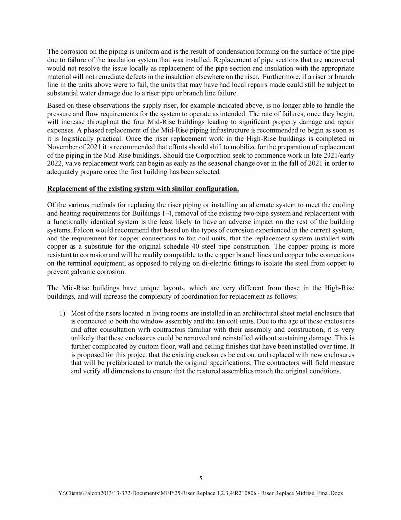
The corrosion on the piping is uniform and is the result of condensation forming on the surface of the pipe due to failure of the insulation system that was installed. Replacement of pipe sections that are uncovered would not resolve the issue locally as replacement of the pipe section and insulation with the appropriate material will not remediate defects in the insulation elsewhere on the riser. Furthermore, if a riser or branch line in the units above were to fail, the units that may have had local repairs made could still be subject to substantial water damage due to a riser pipe or branch line failure.
Based on these observations the supply riser, for example indicated above, is no longer able to handle the pressure and flow requirements for the system to operate as intended. The rate of failures, once they begin, will increase throughout the four Mid-Rise buildings leading to significant property damage and repair expenses. A phased replacement of the Mid-Rise piping infrastructure is recommended to begin as soon as it is logistically practical. Once the riser replacement work in the High-Rise buildings is completed in November of 2021 it is recommended that efforts should shift to mobilize for the preparation of replacement of the piping in the Mid-Rise buildings. Should the Corporation seek to commence work in late 2021/early 2022, valve replacement work can begin as early as the seasonal change over in the fall of 2021 in order to adequately prepare once the first building has been selected. Replacement of the existing system with similar configuration. Of the various methods for replacing the riser piping or installing an alternate system to meet the cooling and heating requirements for Buildings 1-4, removal of the existing two-pipe system and replacement with a functionally identical system is the least likely to have an adverse impact on the rest of the building systems. Falcon would recommend that based on the types of corrosion experienced in the current system, and the requirement for copper connections to fan coil units, that the replacement system installed with copper as a substitute for the original schedule 40 steel pipe construction. The copper piping is more resistant to corrosion and will be readily compatible to the copper branch lines and copper tube connections on the terminal equipment, as opposed to relying on di-electric fittings to isolate the steel from copper to prevent galvanic corrosion. The Mid-Rise buildings have unique layouts, which are very different from those in the High-Rise buildings, and will increase the complexity of coordination for replacement as follows:
1) Most of the risers located in living rooms are installed in an architectural sheet metal enclosure that is connected to both the window assembly and the fan coil units. Due to the age of these enclosures and after consultation with contractors familiar with their assembly and construction, it is very unlikely that these enclosures could be removed and reinstalled without sustaining damage. This is further complicated by custom floor, wall and ceiling finishes that have been installed over time. It is proposed for this project that the existing enclosures be cut out and replaced with new enclosures that will be prefabricated to match the original specifications. The contractors will field measure and verify all dimensions to ensure that the restored assemblies match the original conditions.

6
Y:\Clients\Falcon2013\13-372\Documents\MEP\25-Riser Replace 1,2,3,4\R210806 - Riser Replace Midrise_Final.Docx
2: Typical Detail for Window Riser Enclosures at Mid-Rise Buildings
Draft Detail from Riser Replacement Plans
While this is a big change from the work that has been performed in the High-Rise buildings, since there will be limited work required on the plaster walls in these locations, it should lead to a cleaner and faster installation.
2) Location of Kitchens: In all four Mid-Rise buildings there are single floor dwelling units (flats)
with western exposures that have kitchens that are located at the building’s exterior wall. These kitchens are not provided with HVAC from the two-pipe system, but a separate steam system that provides heat to a single convector beneath the window. The steam system also provides heat to the hallways. In all of these cases the HVAC riser piping, steam piping, natural gas piping, and domestic water plumbing for the kitchens is located in a chase at the exterior wall behind the cabinets, range and oven.
In order to replace the HVAC risers at these locations the kitchen cabinets, ranges, and ovens would need to be removed. This would be expensive for the Corporation and invasive to the residents. An alternate location for the risers has been proposed on the opposite wall from where they are presently located. Falcon has evaluated the structural implications and it will be possible to create new penetrations for the risers to pass between floors. This will require a small pipe chase in the bedroom and simplify the process at these locations, allowing easier access for maintenance in the future and the possibility to add new heating/cooling fan coil units to the kitchens.

7
Y:\Clients\Falcon2013\13-372\Documents\MEP\25-Riser Replace 1,2,3,4\R210806 - Riser Replace Midrise_Final.Docx
3: Rendering demonstrating wall reconstruction and new pipe chase
4. Existing configuration of Riser Piping and Branch Lines at One Level Flat
8
Y:\Clients\Falcon2013\13-372\Documents\MEP\25-Riser Replace 1,2,3,4\R210806 - Riser Replace Midrise_Final.Docx
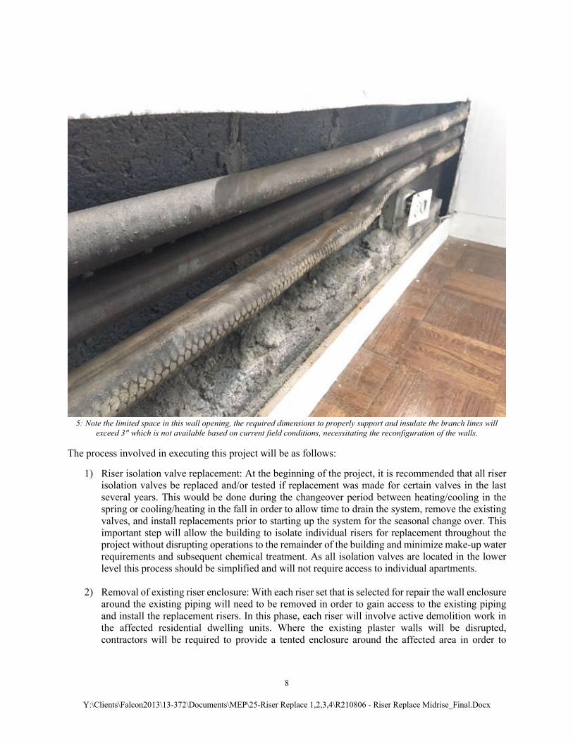
5: Note the limited space in this wall opening, the required dimensions to properly support and insulate the branch lines will
exceed 3" which is not available based on current field conditions, necessitating the reconfiguration of the walls.
The process involved in executing this project will be as follows:
1) Riser isolation valve replacement: At the beginning of the project, it is recommended that all riser isolation valves be replaced and/or tested if replacement was made for certain valves in the last several years. This would be done during the changeover period between heating/cooling in the spring or cooling/heating in the fall in order to allow time to drain the system, remove the existing valves, and install replacements prior to starting up the system for the seasonal change over. This important step will allow the building to isolate individual risers for replacement throughout the project without disrupting operations to the remainder of the building and minimize make-up water requirements and subsequent chemical treatment. As all isolation valves are located in the lower level this process should be simplified and will not require access to individual apartments.
2) Removal of existing riser enclosure: With each riser set that is selected for repair the wall enclosure around the existing piping will need to be removed in order to gain access to the existing piping and install the replacement risers. In this phase, each riser will involve active demolition work in the affected residential dwelling units. Where the existing plaster walls will be disrupted, contractors will be required to provide a tented enclosure around the affected area in order to

9
Y:\Clients\Falcon2013\13-372\Documents\MEP\25-Riser Replace 1,2,3,4\R210806 - Riser Replace Midrise_Final.Docx
prevent dust and debris from collecting in the dwelling units. Contractors will provide air filtration in order to manage dust within the enclosure. At this time, the demolition contractor can also provide testing of the materials in order to identify mold growth, and the presence of asbestos containing materials in the walls and piping insulation. The contractors will provide a temporary wall enclosure around the riser piping once the walls have been removed. At this time, the Corporation may choose to provide temporary heating and cooling units to the residents in affected areas in order to minimize discomfort during the process, as has been done in the High-Rise buildings. As the timeline for each set of risers will be shorter on this project, this step may be less necessary. Where the sheet metal enclosures are being removed in the living rooms and replaced, the contractors will install all necessary protections to prevent dust and debris from spreading in the dwellings, which may also include use of tenting.
3) Removal of existing riser piping: Prior to the removal of the tented enclosure the original riser piping will be removed, as well as abatement of any hazardous materials that may be present on or around the piping. At the end of this phase the contractor will remove the tented enclosure and maintain the temporary wall enclosure. The total time expected for this step and the previous wall removal step is approximately 2 – 3 days. Piping will be removed floor by floor in sequence from the top of the riser to the bottom. The supply, return, and condensate drain piping will be removed.
4) Installation of replacement riser and branch line piping: Following completion of the piping demolition, the contractor will proceed with installation of the replacement riser piping from the bottom of the building to the top. Typically for buildings 5 and 6, two floors per day per riser are completed requiring a minimum of two consecutive days of access per dwelling unit in order to install the riser piping on each floor. For the Mid-Rise buildings, we will be evaluating different paces of construction with the hope of speeding this up to complete each building in a shorter time frame and allow an overall quicker phasing of the project. The contractor will pressure test each floor as it is completed. Following the completion of the piping installation, the pipe will be insulated and all penetrations between fire rated assemblies will be fire stopped. At the end of work each day, the contractor will restore the temporary wall enclosure. It should be noted that the fire stopping observed in Buildings 5 and 6, as well as during preliminary work in the Mid-Rise buildings, has been in very poor condition. In addition to greatly reducing the risk of water damage from piping failure and condensation leaks, this project will improve the overall fire safety of all buildings.
5) Automatic air vents will be installed at the top of the risers and at high points in all piping with drains installed at low points in piping as well as a provision for draining individual fan coil units in the event that maintenance is required. This will be carefully coordinated due to the arrangement of the penthouse apartments. The existing risers terminate below the penthouse with branch lines routed from the crawlspace beneath these apartments as the fan coils are not in line with the floors below due to the differing layout. Provisions will be made to remove air from the system at the riser high points in the crawl space as well as in the penthouse when those fan coil units are re-piped.
6) Municipal inspection: Following completion of the riser piping installation and restoration of service to the affected dwelling units the contractor will coordinate municipal inspections to verify piping installation and fire stopping. Typically, access will be required to all units on the day of the inspection. Inspections are conducted at the conclusion of work on each set of risers. Following completion of inspections, the temporary wall enclosures will be restored.

10
Y:\Clients\Falcon2013\13-372\Documents\MEP\25-Riser Replace 1,2,3,4\R210806 - Riser Replace Midrise_Final.Docx
7) Closure of the riser enclosure and restoration of HVAC service to the affected lines: Following approval from the Fort Lee Building Department, the contractor will arrange for permanent closure of the walls. Typically, the walls will be closed with gypsum board to allow easier access in the future and to facilitate installation of access doors to valve locations. The contractor will be required to finish the wall, so it is ready for paint.
6: Examples of Riser Replacement Project in Progress
Replacement of the existing system with a single pipe, TACO Load-Match type system.
As noted above, the default scope of work for this project would be to replace the existing two pipe schedule 40 steel pipe arrangement, with a similar two pipe Type L copper piping system. All piping between the existing isolation valves, and the isolation valves would be replaced with the new copper system provided with di-electric fittings to isolate the copper system from the existing steel supply and return headers located in the basement. As with the High-Rise buildings, prior to commencing the development of the design plans for the Mid-Rise buildings, alternate replacement strategies were evaluated in order to determine if there was lower cost, less invasive option, that might promote some additional benefits to the community. One of the options studied for the High-Rise buildings was the conversion from a two-pipe system to a single pipe system. This would reduce the material requirements for the project, increase the pace at which work could be performed and potentially reduce the energy consumption at each of the buildings. This option was not implemented at the High-Rise buildings due to the size of the systems and difficulty in implementing. The height of the Mid-Rise buildings would more easily accommodate this type of change but the different system layout, (both the supply and returns being fed from the bottom of the building as opposed to the reverse return system at the High-Rises), would make implementation very costly as a major system configuration change would be required. In addition, the offsets to serve the penthouse level above the riser terminations would also make this impractical. This would convert the existing two pipe system to a single pipe. In this scenario each fan coil unit would be provided with an individual circulator pump powered from the fan coil electricity source that was set for the specific flow rate required to meet the cooling and heating load of the space. In this case the piping would be fabricated with schedule 40 steel, and likely installed with a grooved coupling system in order to be made compatible with the special Load Match tee’s that are required. The cost of this installation would be lower than the “in-kind” replacement due to the lower cost of installation, installing a single pipe, plus the replacement drain line in lieu of the supply and return pipe and the drain line.

11
Y:\Clients\Falcon2013\13-372\Documents\MEP\25-Riser Replace 1,2,3,4\R210806 - Riser Replace Midrise_Final.Docx
Falcon conducted a high-level system analysis, and while further study may help refine the analysis, it is our preliminary finding that this system arrangement will not likely be suitable for the building, due to the increase in flow that will be required. The Corporation is currently completing extensive central plant upgrades that lock the project in at certain flow rates throughout both the heating and cooling systems. In order to operate with the single pipe Load Match system, the new central plant will need to operate outside of its design parameters. For example, in order to achieve the necessary flow at the fan coil units during cooling mode, the plant requires substantially more flow to the fan coil loops due to changes in water temperature delivered to the fan coils from floor to floor; the new chillers and pumps are not capable of accommodating this. Had this option been deemed feasible, the construction process would be similar to what was identified above with the exception that enlarging the original penetrations between floors would be required due to the increase in pipe size required for the single pipe design. This would also require additional patching with fire rated mortar to close the unused penetration. Alternate Material Selection. As discussed, the existing riser piping in all four Mid-Rise buildings is schedule 40 steel. Replacement of these pipes with copper has been proposed. Additional alternate materials have been evaluated, specifically Uponor ProPEX which is a plastic pipe (crosslinked polyethylene) that is becoming more popular in this type of application. This material is resilient, can be installed quickly, and could potentially reduce the cost of the project. However, due to the structural constraints and required piping support mechanisms, it would not be appropriate for this application. Replacement of the existing system with modifications to improve quality of life to the Mid-Rise unit residents. As noted above, we are recommending the abandonment of the existing risers on the west side of the Mid-Rise building that would disrupt the kitchens. One of the major sources of complaints from unit residents is the steam hammer/water hammer noises that occur during heating season from the steam lines that serve the kitchens and the hallways. The steam piping, condensate return piping, and branch piping to the convectors are largely inaccessible due to the layouts of the kitchens. This leads to difficulty in replacing steam traps and correcting pipe pitch issues that are the source of this noise. When live steam comes into contact with steam condensate that may have settled in a horizontal section of steam piping, the condensate flashes back to steam and resulting pressure differential creates this noise. The proposed design abandons these steam convectors and new fan coil units are proposed to be installed in the kitchens. These new fan coils will be tied into the adjacent risers, and the shareholders in the affected apartments will be provided with both heating and cooling in the kitchens moving forward.

12
Y:\Clients\Falcon2013\13-372\Documents\MEP\25-Riser Replace 1,2,3,4\R210806 - Riser Replace Midrise_Final.Docx
Recommendations. Based on our review of the two system types presented above, Falcon is recommending that the Corporation plan for a phased riser replacement project in each Mid-Rise building to include the vertical riser components, condensate drain lines, and branch lines connecting the fan coil units, in addition to the horizontal offset piping that exist on the ground floor and beneath the penthouse. As an additional component to this project, we recommend abandoning the existing riser piping, including the steam lines on the western exposures of the Mid-Rise building, where the existing system passes through the flat apartments with kitchens located on the west facing side of the Mid-Rise buildings. New pipe chases will be constructed, and fan coil units will be added to the kitchens in order to add air conditioning to these spaces as well as replace the heating elements that would be abandoned. Falcon is in possession of mostly complete sets of original construction plans for the entire community. These plans were used in addition to field observations to develop the scope of work for this project. While the records that exist are an excellent resource, the documentation specifically related to the HVAC and Plumbing systems is more complete for Buildings 3 and 4. All four buildings are substantially similar, but due to the fact that a more complete set of records exist for Buildings 3 and 4 we are recommending starting there in order to be better able to address any field conditions that might be uncovered. Any lessons learned would then be able to be applied to the remainder of the Buildings. If the Corporation elects to move forward with this project Falcon recommends the work begin in either Building 3 or Building 4 as a Pilot Project. Following completion of work on the Pilot Project Building, work should shift to one of the remaining buildings. Final sequencing of the project and scheduling will be determined as work on the pilot project progresses. This will be determined in coordination with the selected Contractor and the Corporation and will be based on field conditions and the urgency of any conditions that may change during the project execution. Scheduling of the work and access requirements will be benchmarked during the Pilot Phase in order to assess the overall impact on the community. Adjustments will be made during the initial phases to reduce inconvenience as much as possible. Finally, when replacing these systems, we recommend changing how the branch line connections between the riser and the fan coil units are configured. This is particularly of note at all locations that do not feature the risers in sheet metal enclosures (at these locations the branch lines and fan coil locations and all-in close proximity to the risers). The current arrangement for these systems has the branch lines routed to the fan coil unit inside the wall cavity, the block wall that makes up the building façade has been channeled when the buildings were originally constructed. The current energy code requires additional insulation that will not fit in the existing location without compressing the insulation between the plaster finish and block wall. This will result in compromised insulation values and condensation that will damage the walls. Many unit owners in these buildings have already experienced this. In some cases when making repairs the branch lines were brought outside of the wall and a new framed out enclosure was constructed to conceal this piping. We recommend implementing this throughout the Mid-Rise buildings in two ways.
1) Where the new risers will be installed on the west side of the Mid-Rise buildings adjacent to the kitchen, instead of just framing out the new pipe chase a new wall should be constructed at the heigh of the fan coil unit and the full depth of the new pipe chase is approximately 10 inches. It will allow the existing branch line piping to be abandoned, and the new piping can be installed with the proper insulation, proper pitch for the drain line and plenty of room for valves and supports without compromising the design.

13
Y:\Clients\Falcon2013\13-372\Documents\MEP\25-Riser Replace 1,2,3,4\R210806 - Riser Replace Midrise_Final.Docx
2) Where the new risers are not required, we recommend building out the knee wall enclosure around
the branch lines at the approximate height of the fan coil unit to a depth of approximately 5 inches in order to accommodate the same, eliminating and abandoning the old piping arrangement and installing the new lines with adequate spacing to prevent development of moisture in the space and allowing the insulation to perform as intended. The contractors will relocate and extend any outlets that would be affected to the outside of the new enclosure in both cases.
The plans and specifications that have been developed by Falcon include the recommendations made above. Falcon does not recommend that the Corporation attempt to contract with multiple independent contractors to conduct various phases of the project (i.e., hiring a separate general contractor or carpenter to perform selective demolition, insulation, core drilling etc.). Selected Bidders should be qualified mechanical contractors with experience in this type of work who will engage subcontractors to deal with any asbestos/mold remediation, demolition and reconstruction of the existing walls/enclosures concealing the risers as well as core drilling new openings for the relocated risers.
Sincerely, James A Trynosky, P.E., LEED AP Vice President of MEP Services JAT/eb
14
Y:\Clients\Falcon2013\13-372\Documents\MEP\25-Riser Replace 1,2,3,4\R210806 - Riser Replace Midrise_Final.Docx
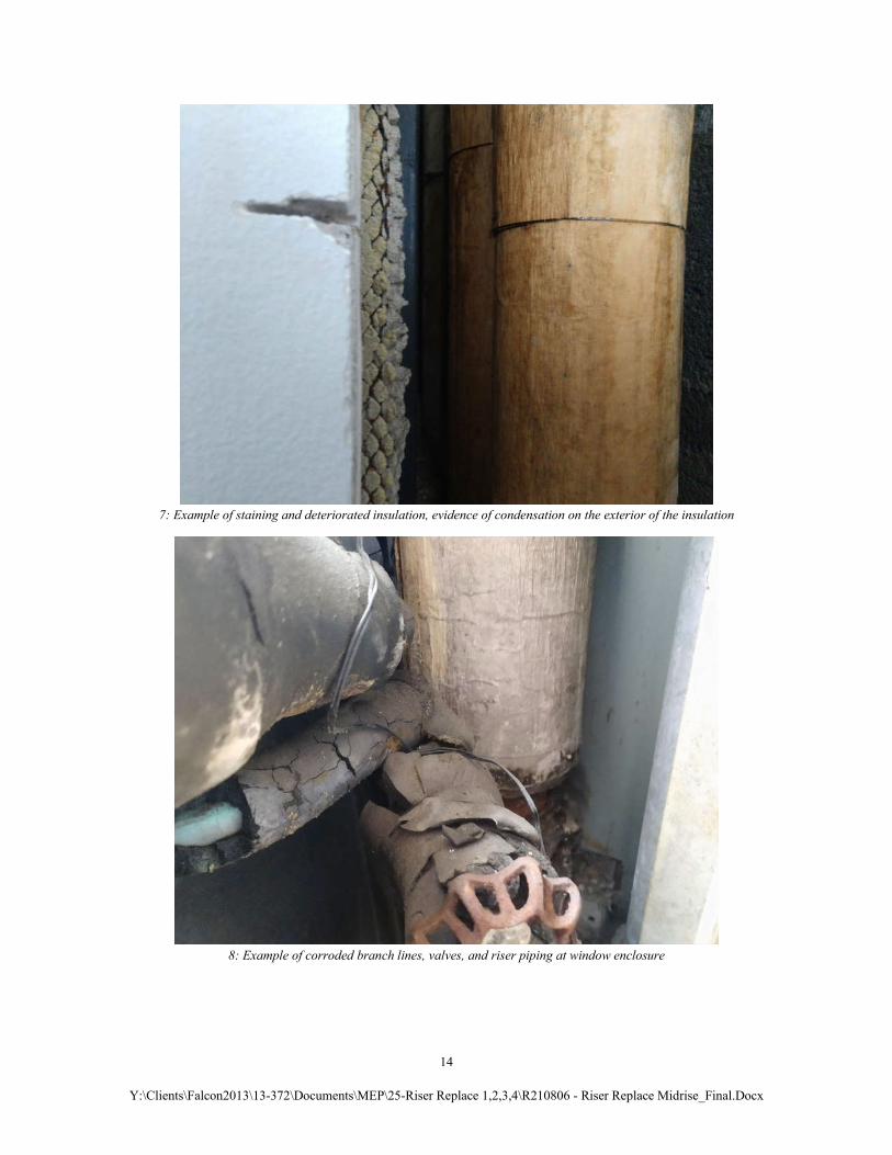
7: Example of staining and deteriorated insulation, evidence of condensation on the exterior of the insulation
8: Example of corroded branch lines, valves, and riser piping at window enclosure
15
Y:\Clients\Falcon2013\13-372\Documents\MEP\25-Riser Replace 1,2,3,4\R210806 - Riser Replace Midrise_Final.Docx
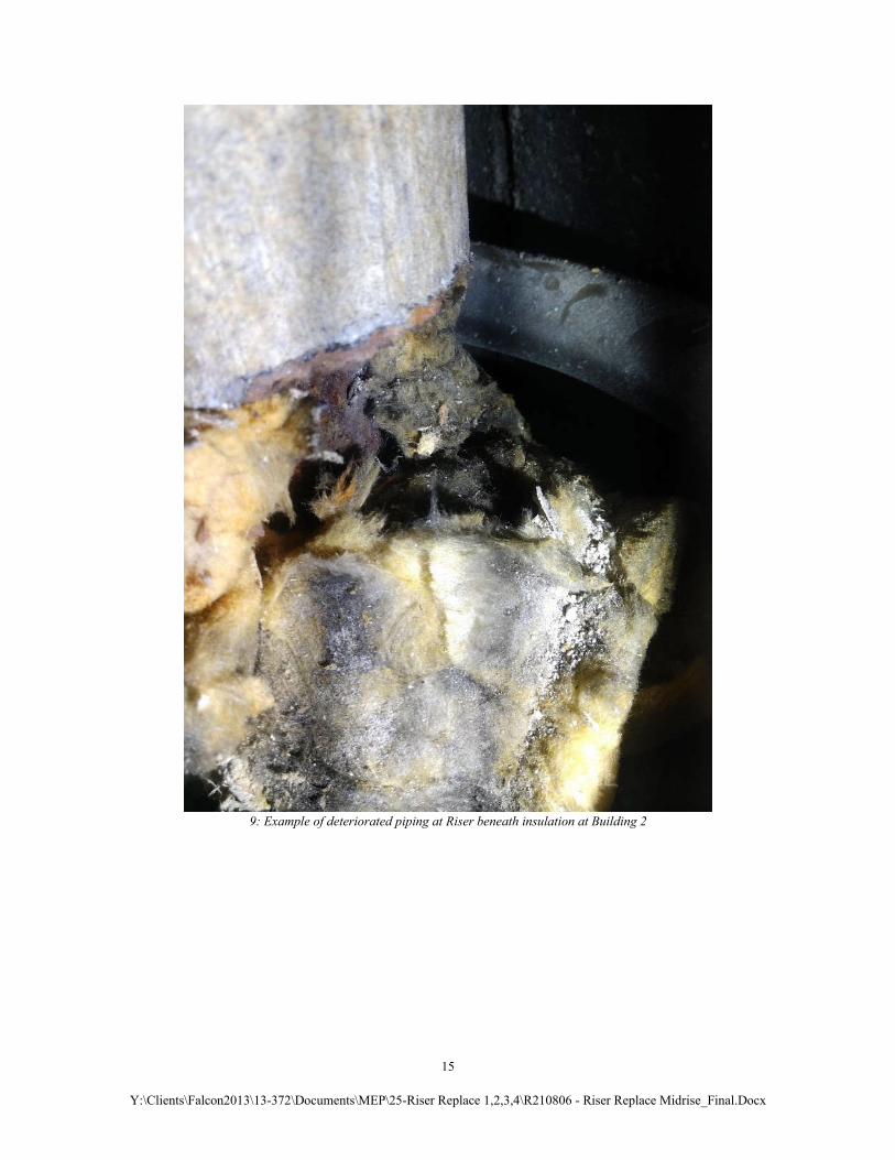
9: Example of deteriorated piping at Riser beneath insulation at Building 2
16
Y:\Clients\Falcon2013\13-372\Documents\MEP\25-Riser Replace 1,2,3,4\R210806 - Riser Replace Midrise_Final.Docx
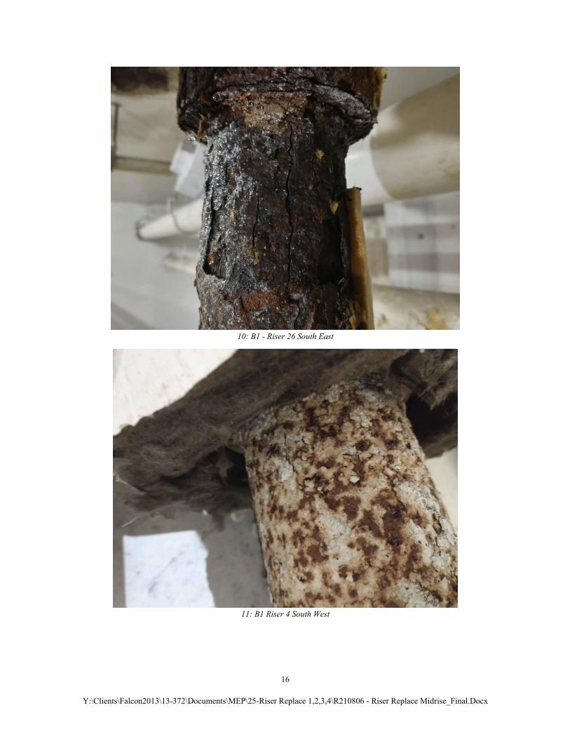
10: B1 - Riser 26 South East
11: B1 Riser 4 South West
17
Y:\Clients\Falcon2013\13-372\Documents\MEP\25-Riser Replace 1,2,3,4\R210806 - Riser Replace Midrise_Final.Docx
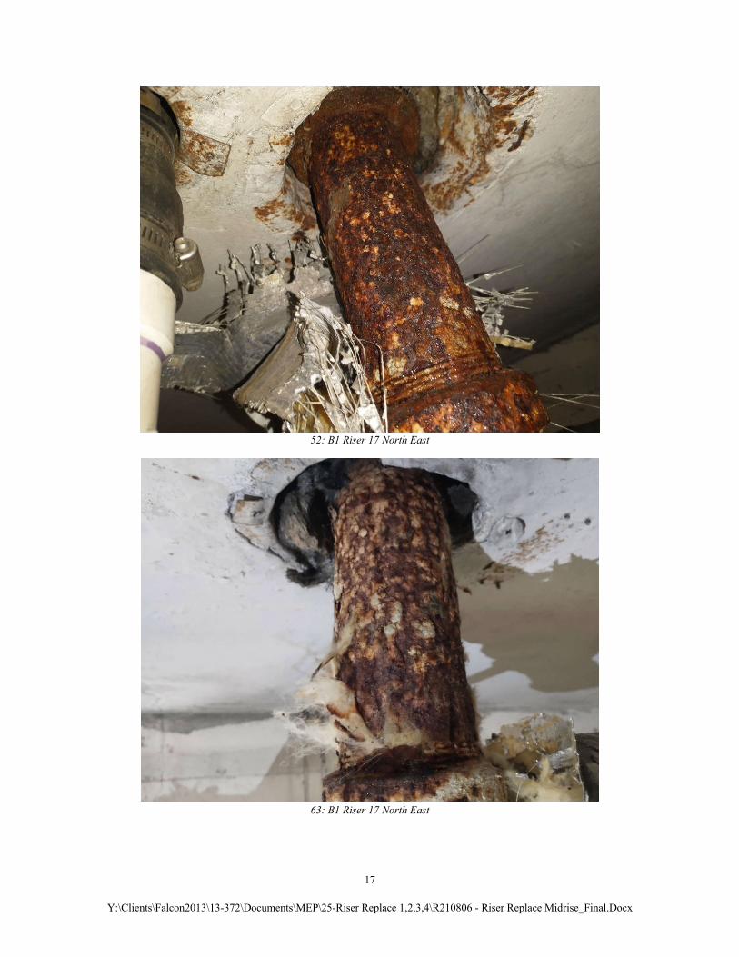
52: B1 Riser 17 North East
63: B1 Riser 17 North East
18
Y:\Clients\Falcon2013\13-372\Documents\MEP\25-Riser Replace 1,2,3,4\R210806 - Riser Replace Midrise_Final.Docx
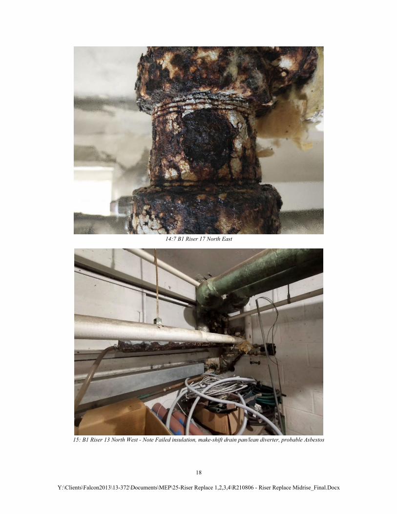
14:7 B1 Riser 17 North East
15: B1 Riser 13 North West - Note Failed insulation, make-shift drain pan/lean diverter, probable Asbestos
19
Y:\Clients\Falcon2013\13-372\Documents\MEP\25-Riser Replace 1,2,3,4\R210806 - Riser Replace Midrise_Final.Docx
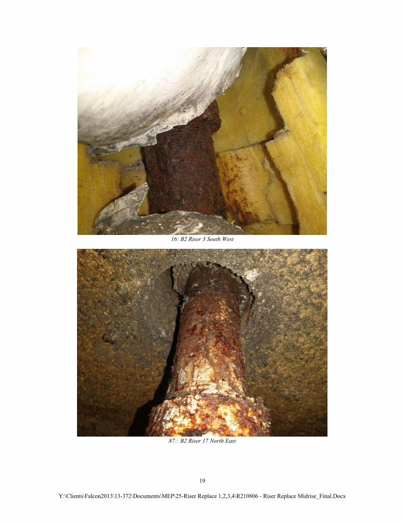
16: B2 Riser 3 South West
87:: B2 Riser 17 North East

20
Y:\Clients\Falcon2013\13-372\Documents\MEP\25-Riser Replace 1,2,3,4\R210806 - Riser Replace Midrise_Final.Docx
18: B2 Riser 16 North East
19: B2 Riser 15 North East
21
Y:\Clients\Falcon2013\13-372\Documents\MEP\25-Riser Replace 1,2,3,4\R210806 - Riser Replace Midrise_Final.Docx
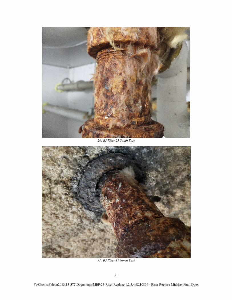
20: B3 Riser 25 South East
91: B3 Riser 17 North East
22
Y:\Clients\Falcon2013\13-372\Documents\MEP\25-Riser Replace 1,2,3,4\R210806 - Riser Replace Midrise_Final.Docx
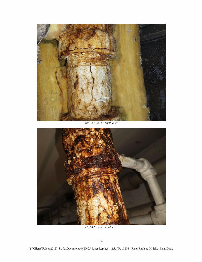
10: B3 Riser 17 North East
11: B4 Riser 21 South East
23
Y:\Clients\Falcon2013\13-372\Documents\MEP\25-Riser Replace 1,2,3,4\R210806 - Riser Replace Midrise_Final.Docx
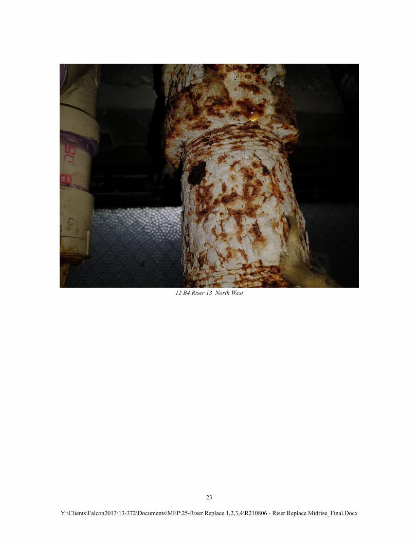
12 B4 Riser 13 North West