replacement of rti display unit to nav in volvo (rti cd ... for rti volvo.pdf · replacement of rti...
TRANSCRIPT
(This will work both for the small and the wide Display)
Video can be seen on: http://www.nasab.com/Volvo/tip-trick.htm where we have put up some video
from our test and the last one which is a final working Standard Navigation in Volvo RTI unit.
(Final edition together with NAV Voice Guide over TV tuner)
First of all everything depends on how much you want to spend both in money and time (When we refer to
cost we do not consider NAV unit only the cost for some electronic parts, connectors and cables):
1. You can make the replacement very easy and cheap by just take out the RTI Display and replace
it mechanically with a TOMTOM, Garmin or Lark NAV which has 4.3 inch Display and use a
switch to operate the Up/Down and to turn the NAV On/Off. This is the simplest way of doing it.
2. You can use a sophisticated pc board with microprocessor to communicate with the can bus and
by then you would be able to operate the RTI Up/Down with the original keys on the steering
wheel or by the remote control. This is very complicated and difficult solutions and expensive and
you need to have know how, how to programming microprocessors and not very easy for the
common person to achieve. In this way you also have to mechanically replace the RTI display
with some kind of NAV.
Our Project
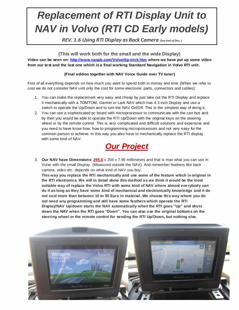
3. Our NAV have Dimensions: 295.6 x 204 x 7.95 millimeters and that is max what you can use in
Volvo with the small Display. (Measured outside the NAV). And remember feathers like back
camera, video etc. depends on what kind of NAV you buy.
This way you replace the RTI mechanically and use some of the feature which is original in
the RTI electronics. We will in detail show this method as we think it would be the most
suitable way of replace the Volvo RTI with some kind of NAV where almost eve rybody can
do it as long as they have some kind of mechanical and electronically knowledge and it do
not cost more than between 10 to 50 Euro in material . We choose this way where you do
not need any programming and still have some feathers which operate the RTI
Display/NAV Up/down starts the NAV automatically when the RTI goes “Up” and shuts
down the NAV when the RTI goes “Down”. You can also use the original bottoms on the
steering wheel or the remote control for sending the RTI Up/Down, but nothing else.
Replacement of RTI Display Unit to
NAV in Volvo (RTI CD Early models) REV. 1.6 Using RTI Display as Back Camera (See end of Doc.)
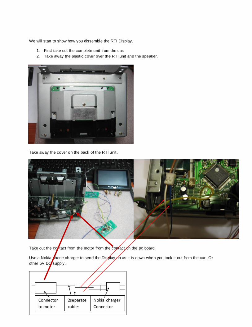
We will start to show how you dissemble the RTI Display.
1. First take out the complete unit from the car.
2. Take away the plastic cover over the RTI unit and the speaker.
Take away the cover on the back of the RTI unit .
Take out the contact from the motor from the contact on the pc board.
Use a Nokia phone charger to send the Display up as it is down when you took it out from the car. Or
other 5V DC supply.
Connector
to motor
Nokia charger
Connector
2separate
cables
Take 2 small cable peaces and connect one to the negative (outside) of the Nokia charger and the other
one to the hole on the middle of Nokia charger. Now you will have access to 6V DC which we will use to
start the motor by connect the other end of those cables to the connector (just stick the cable into the
connector) coming from the motor in the RTI which are a 9V DC motor. If the RTI do not move but the
motor are running you have to change the position of the cable into the connector. When the RTI unit is in
the top it will automatically stop in the right position but the motor will still be running as long as you have
the Nokia charger connected. Take away the Nokia connector and the motor will stop.
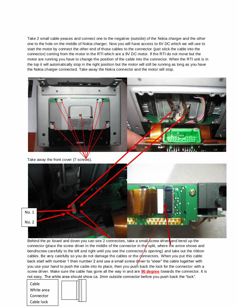
Take away the front cover (7 screws).
Behind the pc board and down you can see 2 connectors, take a small screw driver and bend up the
connector (place the screw driver in the middle of the connector in the split, where the arrow shows and
bend/screw carefully to the left and right until you see the connector is opening) and take out the ribbon
cables. Be very carefully so you do not damage the cables or the connectors. When you put this cable
back start with number 1 then number 2 and use a small screw driver to “steer” the cable together with
you use your hand to push the cable into its place, then you push back the lock for the connector with a
screw driver. Make sure the cable has gone all the way in and are 90 degree towards the connector. It is
not easy. The white area should show ca. 2mm outside connector before you push back the “lock”.
No. 1
No. 2
Cable
White area
Connector
Cable lock

Take away the 2 screws holding the plastic cover over the display and open separate the back side from
the front side of the plastic cover. It will go apart in the bottom and then you have to lift up the back part to
get it separated from the front part. Then take away the 2 screws holding the complete display. Now you
can lift up and out the whole display unit.
Take out all screws holding the pc board and the display. And all the connectors to the display.
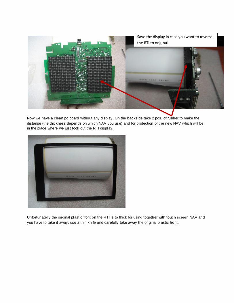
Now we have a clean pc board without any display. On the backside take 2 pcs. of rubber to make the
distanse (the thickness depends on which NAV you use) and for protection of the new NAV which will be
in the place where we just took out the RTI displ ay.
Unfortunatelly the original plastic front on the RTI is to thick for using together with touch screen NAV and
you have to take it away, use a thin knife and carefully take away the original plastic front.
Save the display in case you want to reverse
the RTI to original.
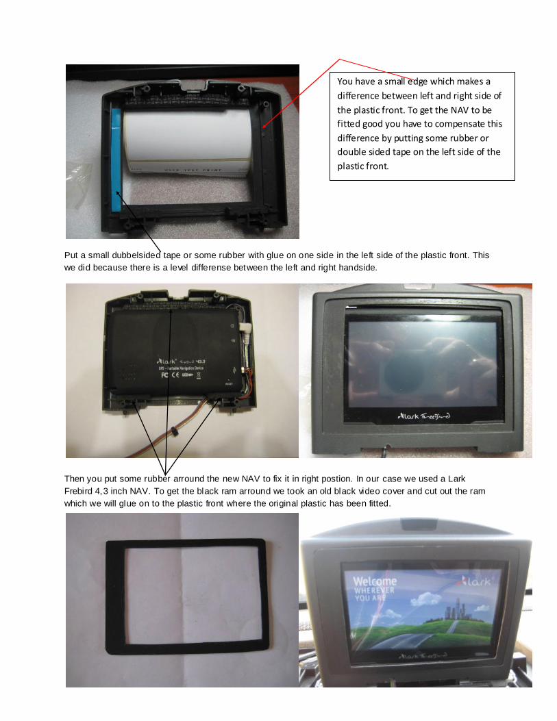
Put a small dubbelsided tape or some rubber with glue on one side in the left side of the plastic front. This
we did because there is a level differense between the left and right handside.
Then you put some rubber arround the new NAV to fix it in right postion. In our case we used a Lark
Frebird 4,3 inch NAV. To get the black ram arround we took an old black video cover and cut out the ram
which we will glue on to the plastic front where the original plastic has been fitted.
You have a small edge which makes a
difference between left and right side of
the plastic front. To get the NAV to be
fitted good you have to compensate this
difference by putting some rubber or
double sided tape on the left side of the
plastic front.
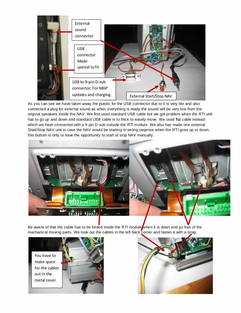
As you can see we have taken away the plastic for the USB connector due to it is very tite and also
connected a plug for external sound as when everything is ready the sound will be very low from the
original speakers inside the NAV. We first used standard USB cable but we got problem when the RTI unit
has to go up and down and standard USB cable is to thick to easely move. We used flat cable instead
which we have connected with a 9 pin D-sub outside the RTI module. We also has made one external
Start/Stop NAV unit in case the NAV would be starting in wrong seqense when the RTI goes up or down,
this buttom is only to have the opportunity to start or stop NAV manually.
Be awere of that the cable has to be folded inside the RTI module when it is down and go free of the
machanical moving parts. We took out the cables in the left back corner and fasten it with a strap.
External
sound
connector
USB
connector
Made
special to fit
USB to 9-pin D-sub
connector. For MAP
updates and charging. External Start/Stop NAV
You have to
make space
for the cables
out in the
metal cover.
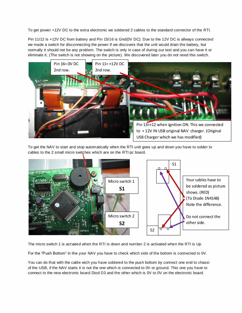
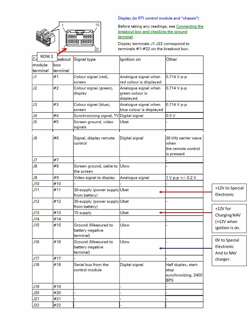
To get power +12V DC to the extra electronic we soldered 2 cables to the standard connector of the RTI.
Pin 11/12 is +12V DC from battery and Pin 15/16 is Gnd(0V DC). Due to the 12V DC is allways connected
we made a switch for disconnecting the power if we discovers that the unit would drain the battery, but
normally it should not be any problem. The switch is only in case of during our test and you can have it or
eliminate it. (The switch is not showing on the picture). We discovered later you do not need this switch.
To get the NAV to start and stop automatically when the RTI unit goes up and down you have to solder to
cables to the 2 small micro switches which are on the RTI pc board.
The micro switch 1 is actvated when the RTI is down and number 2 is activated when the RTI is Up.
For the “Push Bottom” in the your NAV you have to check which side of the bottom is connected to 0V.
You can do that with the cable wich you have soldered to the push bottom by connect one end to chassi
of the USB, if the NAV starts it is not the one which is connected to 0V or ground. This one you have to
connect to the new electronic board Diod D3 and the other which is 0V to 0V on the electronic board.
Pin 11= +12V DC
2nd row.
Pin 16= 0V DC
2nd row.
Micro switch 1
S1
Micro switch 2
S2
Your cables have to
be soldered as picture
shows. (RED)
(To Diode 1N4148)
Note the difference.
Do not connect the
other side.
Pin 13=+12 when ignition ON. This we connected
to + 12V IN USB original NAV charger. (Original
USB Charger which we has modified)
S1
S2
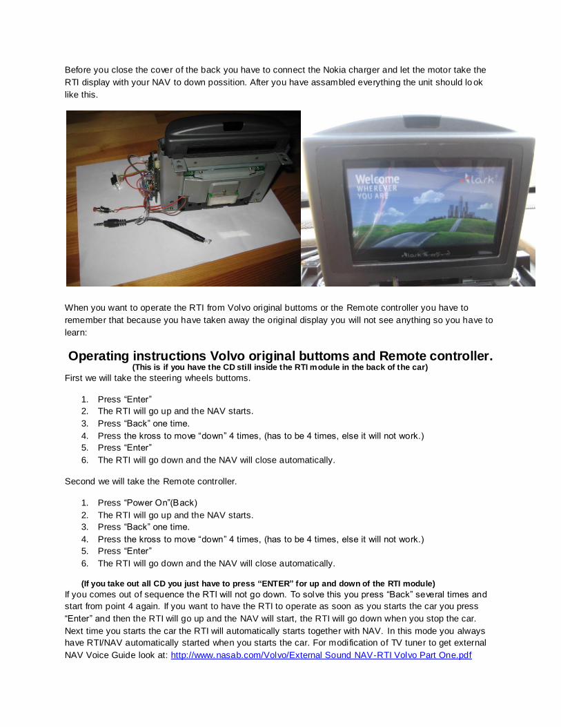
Before you close the cover of the back you have to connect the Nokia charger and let the motor take the
RTI display with your NAV to down possition. After you have assambled everything the unit should lo ok
like this.
When you want to operate the RTI from Volvo original buttoms or the Remote controller you have to
remember that because you have taken away the original display you will not see anything so you have to
learn:
Operating instructions Volvo original buttoms and Remote controller. (This is if you have the CD still inside the RTI module in the back of the car)
First we will take the steering wheels buttoms.
1. Press “Enter”
2. The RTI will go up and the NAV starts.
3. Press “Back” one time.
4. Press the kross to move “down” 4 times, (has to be 4 times, else it will not work.)
5. Press “Enter”
6. The RTI will go down and the NAV will close automatically.
Second we will take the Remote controller.
1. Press “Power On”(Back)
2. The RTI will go up and the NAV starts.
3. Press “Back” one time.
4. Press the kross to move “down” 4 times, (has to be 4 times, else it will not work.)
5. Press “Enter”
6. The RTI will go down and the NAV will close automatically.
(If you take out all CD you just have to press “ENTER” for up and down of the RTI module)
If you comes out of sequence the RTI will not go down. To solve this you press “Back” several times and
start from point 4 again. If you want to have the RTI to operate as soon as you starts the car you press
“Enter” and then the RTI will go up and the NAV will start, the RTI will go down when you stop the car.
Next time you starts the car the RTI will automatically starts together with NAV. In this mode you always
have RTI/NAV automatically started when you starts the car. For modification of TV tuner to get external
NAV Voice Guide look at: http://www.nasab.com/Volvo/External Sound NAV-RTI Volvo Part One.pdf
In this test we have been using Lark Freebird 4.3 inch NAV (Problem only Polish maps), but you can use
whatever NAV in the marked as long it will fit inside the RTI unit where the display have been connected
and has a “Push” bottom to start. We also has made this so if you save the old display and some screws
and the original plastic front you can if you want reverse everything and the Volvo RTI will work as before.
This in case Volvo sometimes maybe do something, but of course it is long time since we stopped to
belive in Santa Clause, but you never know, maybe somebody makes something useful in the future. It is
pitty that with this we lose the back camera options, which you easely can connect to the original display
in the RTI. If somebody needs help or have comments you are welcome to contact us at Special
Machines/Electronic Department by e-mail in english, swedish or norwegian: [email protected]
We wish you Good luck!
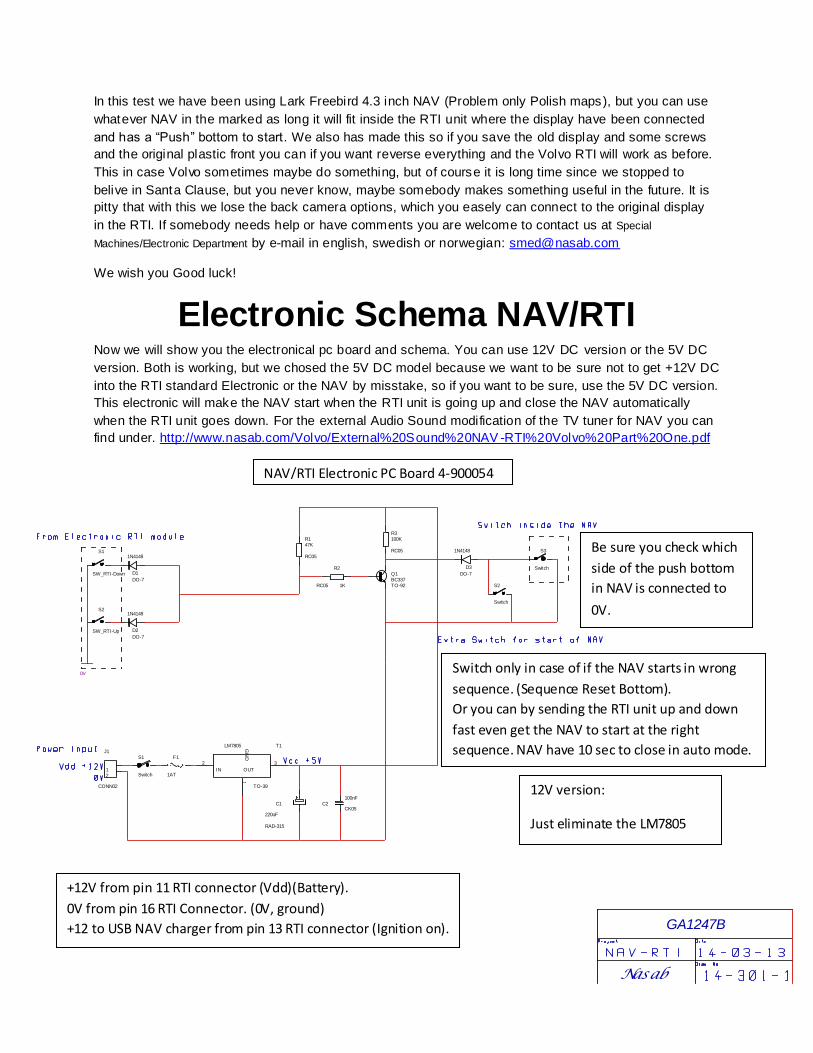
Electronic Schema NAV/RTI Now we will show you the electronical pc board and schema. You can use 12V DC version or the 5V DC
version. Both is working, but we chosed the 5V DC model because we want to be sure not to get +12V DC
into the RTI standard Electronic or the NAV by misstake, so if you want to be sure, use the 5V DC version.
This electronic will make the NAV start when the RTI unit is going up and close the NAV automatically
when the RTI unit goes down. For the external Audio Sound modification of the TV tuner for NAV you can
find under. http://www.nasab.com/Volvo/External%20Sound%20NAV -RTI%20Volvo%20Part%20One.pdf
12V version:
Just eliminate the LM7805
Nasab
R147K
RC05
R2
1KRC05
R3100K
RC05
C1
220uF
RAD-315
C2100nF
CK05
F1
1AT12
J1
CONN02
GA1247B
1G
ND
2
IN
3
OUT
T1LM7805
TO-39
D1
1N4148
DO-7
D2
1N4148
DO-7
Q1BC337TO-92
S1
SW_RTI-Down
S2
SW_RTI-Up
S3
SwitchD3
1N4148
DO-7
S2
Switch
S1
Switch
0V
+12V from pin 11 RTI connector (Vdd)(Battery).
0V from pin 16 RTI Connector. (0V, ground)
+12 to USB NAV charger from pin 13 RTI connector (Ignition on).
Switch only in case of if the NAV starts in wrong
sequence. (Sequence Reset Bottom).
Or you can by sending the RTI unit up and down
fast even get the NAV to start at the right
sequence. NAV have 10 sec to close in auto mode.
Be sure you check which
side of the push bottom
in NAV is connected to
0V.
NAV/RTI Electronic PC Board 4-900054
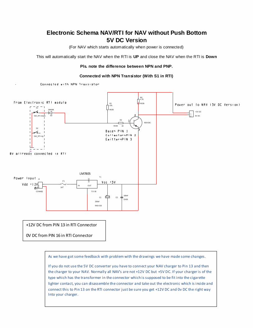
Electronic Schema NAV/RTI for NAV without Push Bottom
5V DC Version (For NAV which starts automatically when power is connected)
This will automatically start the NAV when the RTI is UP and close the NAV when the RTI is Down
Pls. note the difference between NPN and PNP.
Connected with NPN Transistor (With S1 in RTI)
R147K
RC05
R2
1KRC05
C1
220uF
RAD-315
C2100nF
CK05
F1
1AT12
J1
CONN02
GN
D
IN OUT
T1LM2576
TO-39
D2
1N4148S1
SW_RTI-Down
S2
SW_RTI-Up
0V
12 0V DC
+5V DC
R34,7K
RC05
BDX33C
+12V DC from PIN 13 in RTI Connector
0V DC from PIN 16 in RTI Connector
As we have got some feedback with problem with the drawings we have made some changes.
If you do not use the 5V DC converter you have to connect your NAV charger to Pin 13 and then
the charger to your NAV. Normally all NAV’s are not +12V DC but +5V DC. If your charger is of the
type which has the transformer in the connector which is supposed to be fit into the cigarette
lighter contact, you can disassemble the connector and take out the electronic which is inside and
connect this to Pin 13 on the RTI connector just be sure you get +12V DC and 0v DC the right way Into your charger.
LM7805
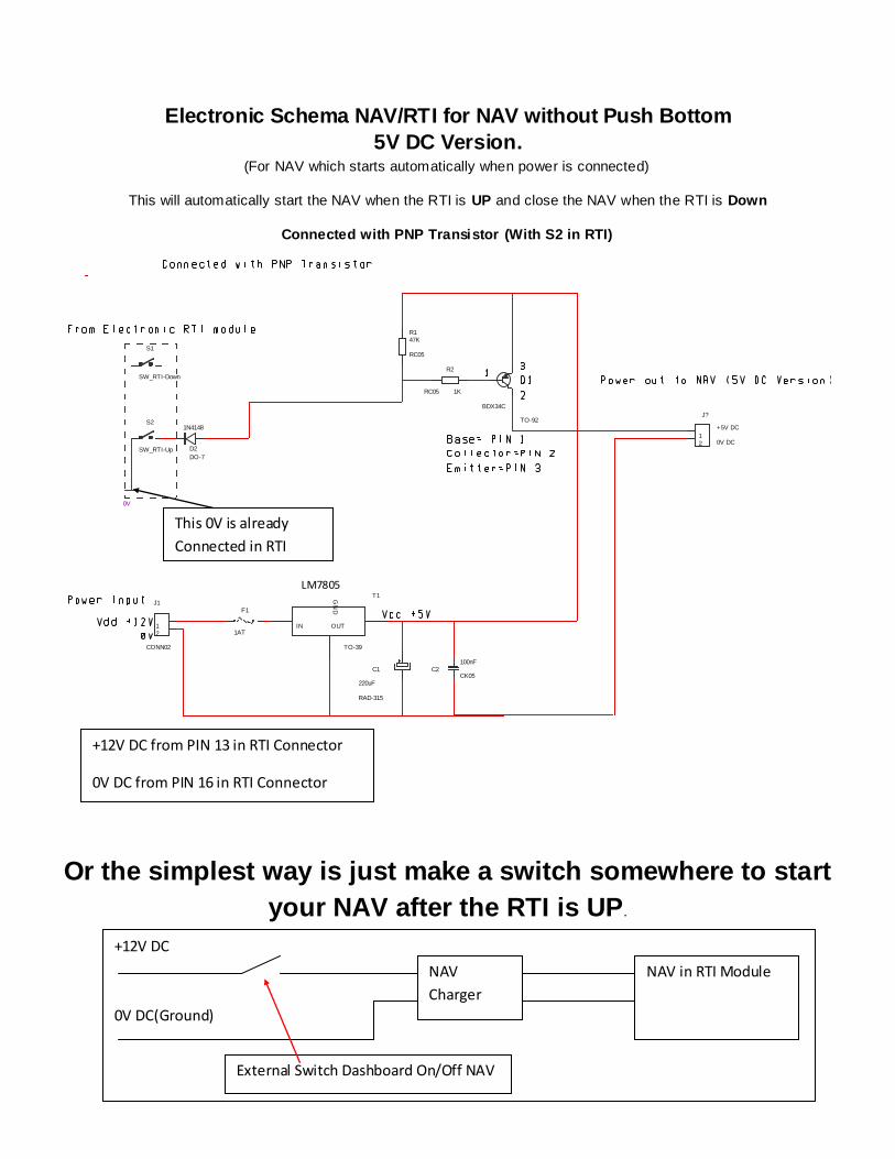
Electronic Schema NAV/RTI for NAV without Push Bottom
5V DC Version. (For NAV which starts automatically when power is connected)
This will automatically start the NAV when the RTI is UP and close the NAV when the RTI is Down
Connected with PNP Transistor (With S2 in RTI)
Or the simplest way is just make a switch somewhere to start
your NAV after the RTI is UP.
R147K
RC05
R2
1KRC05
C1
220uF
RAD-315
C2100nF
CK05
F1
1AT12
J1
CONN02
GN
D
IN OUT
T1LM2576
TO-39
D2
1N4148
DO-7
S1
SW_RTI-Down
S2
SW_RTI-Up
0V
12
J?
0V DC
+5V DC
BDX34C
TO-92
+12V DC from PIN 13 in RTI Connector
0V DC from PIN 16 in RTI Connector
+12V DC
0V DC(Ground)
This 0V is already
Connected in RTI
NAV in RTI Module NAV
Charger
External Switch Dashboard On/Off NAV
LM7805
+12V to Special
Electronic
0V to Special
Electronic
And to NAV
charger.
+12V for
Charging NAV
(+12V when
ignition is on.
ROW 2
Sunday, March 16, 2014
Some result of test:
For the past week we have been having this equipment installed in one of our Volvo V70 01 and the result
has been very good, no problem with the electronic the NAV has been working as it should and the
original bottoms on the steering wheel and the remote controller has been working fine, also the feature
where you are using the NAV and you are on the road and you stops for filling gasoline and you shuts
down the car, the RTI goes down smoothly and starts again when you start the car again. The result of
this modification is very good so far and we will have a look at how to connect the sound to voice guide
channel of the Volvo. The problem is there is no voice guide channel in the original RTI display connector
and we have to go all the way back to the TV module in the back of the car to find a connector which have
voice guide channel or to the radio module. Then you have the Melbus protocol to consider. But we will
see if we can go around this as we have done with the RTI unit already. Would be nice to get the voice
from the NAV to be sent over the voice guide channel or else we have to connect a separate speaker just
for NAV. But that is the last solution we will take, first we will try to go around the Mel bus protocol.
Why we done this:
1. We were tired of Volvo who had not made any maps for Eastern Europe.
2. As we have a factory in Poland and we cannot get any maps at all for Eastern Europe CD version,
they have never made it, only for DVD RTI.
3. Maps for Western Europe inclusive Scandinavian not up to date and will never be.
4. Why have an RTI in a car you cannot use, better modify and use it.
5. And with this you can update the maps by USB and Internet.
The Audio NAV Voice Guide Sound modification to the TV tuner you can find on our web site:
http://www.nasab.com/Volvo/External Sound NAV-RTI Volvo Part One.pdf
To all of you who likes to do this we hope this guide have helped yo u.
Nasab International Corporation Special Machines/Electronic Department.
Contact information if you wonder something: [email protected]
Saturday, May 10, 2014
We have made some more opportunity to connect NAV together with RTI as there has been some
question around this. Pls. see new drawings for +5V versions.
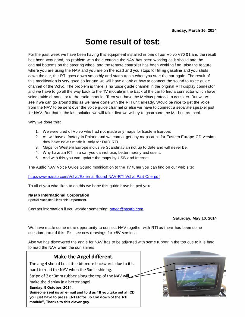
Also we has discovered the angle for NAV has to be adjusted with some rubber in the top due to it is hard
to read the NAV when the sun shines.
Make the Angel different. The angel should be a little bit more backwards due to it is
hard to read the NAV when the Sun is shining.
Stripe of 2 or 3mm rubber along the top of the NAV will
make the display in a better angel. Sunday, 5 October, 2014,
Someone sent us an e-mail and told us “If you take out all CD
you just have to press ENTER for up and down of the RTI
module”, Thanks to this clever guy.
Where you have replaced RTI Display with NAV in Volvo.
(RTI CD Early model) (Second Edition)
We will in this document show how you can use original Volvo sound system for the sound from the new
NAV which you have replaced the RTI Display with.
We will use the TV tuner box in the back of the car.
We first have to make some modification to the TV tuner to get the function we want.
After the first step of modification you can already use the external sound from NAV but only if you set up
TV in the radio unit, then also you will have the function as if you had used the RTI bottoms on the
steering wheel or remote control as the RTI will go up when you set up TV in the radio and the NAV will
automatically start. But in this mode you cannot listen to some radio station or CD Changer or CD,
because the RTI are in TV mode, but you will have voice guide sound from NAV.
So this is not enough and we have to be able to make some more modification so the Voice Guide Sound
from NAV will override the Radio Channel, CD, Tape, CD Changer, Yatour Unit, IPOD unit and every
other equipment you have connected to the Sound system of your Volvo.
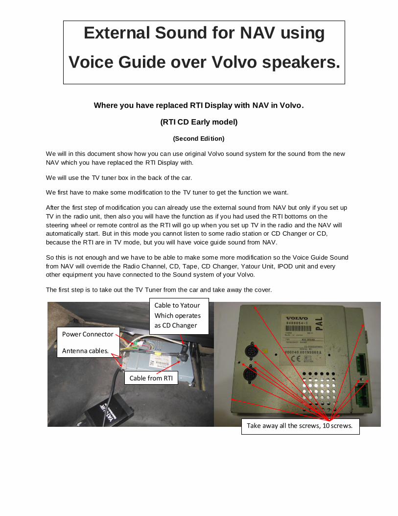
The first step is to take out the TV Tuner from the car and take away the cover.
Take away all the screws, 10 screws.
Cable from RTI
Cable to Yatour
Which operates
as CD Changer Power Connector
Antenna cables.
External Sound for NAV using
Voice Guide over Volvo speakers.
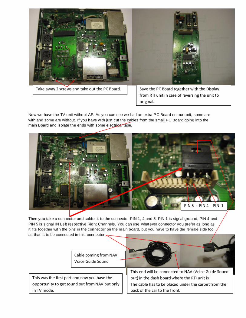
Now we have the TV unit without AF. As you can see we had an extra PC Board on our unit, some are
with and some are without. If you have with just cut the cables from the small PC Board going into the
main Board and isolate the ends with some electrical tape.
Then you take a connector and solder it to the connector PIN 1, 4 and 5. PIN 1 is signal ground, PIN 4 and
PIN 5 is signal IN Left respective Right Channels. You can use whatever connector you prefer as long as
it fits together with the pins in the connector on the main board, but you have to have the female side too
as that is to be connected in this connector.
Take away 2 screws and take out the PC Board. Save the PC Board together with the Display
from RTI unit in case of reversing the unit to
original.
PIN 5 - PIN 4 - PIN 1
Cable coming from NAV
Voice Guide Sound
This end will be connected to NAV (Voice Guide Sound
out) in the dash board where the RTI unit is.
The cable has to be placed under the carpet from the
back of the car to the front.
This was the first part and now you have the
opportunity to get sound out from NAV but only
in TV mode.

Connector
To reverse camera and video)
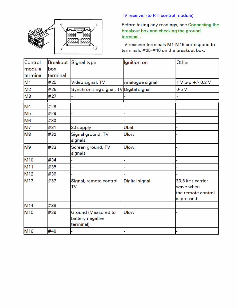
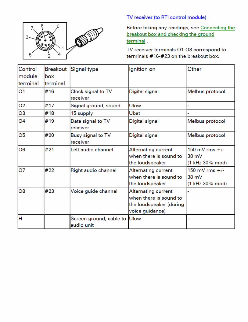
To RTI Control module
Connector
To RTI control module
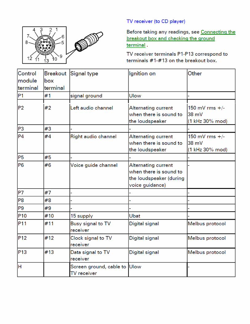
To CD Changer, Yatour
etc.
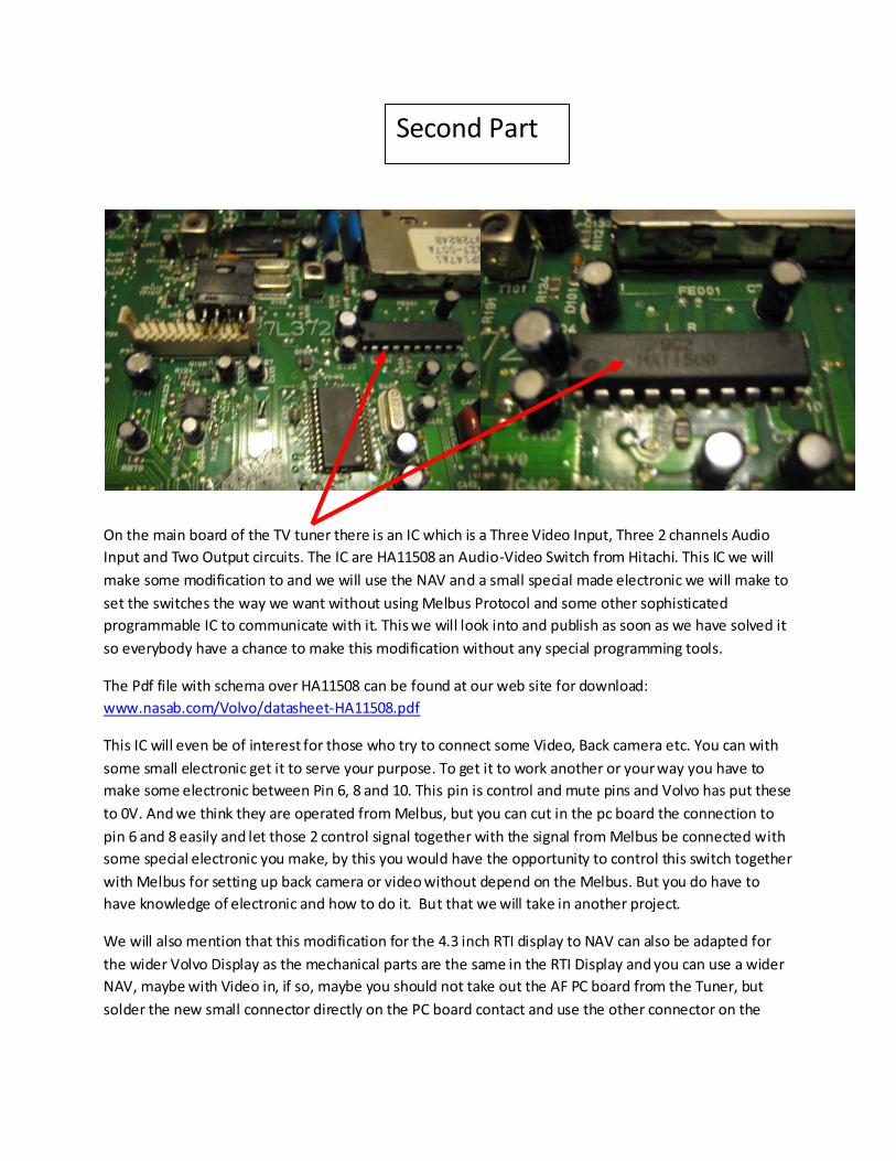
On the main board of the TV tuner there is an IC which is a Three Video Input, Three 2 channels Audio
Input and Two Output circuits. The IC are HA11508 an Audio-Video Switch from Hitachi. This IC we will
make some modification to and we will use the NAV and a small special made electronic we will make to
set the switches the way we want without using Melbus Protocol and some other sophisticated
programmable IC to communicate with it. This we will look into and publish as soon as we have solved it
so everybody have a chance to make this modification without any special programming tools.
The Pdf file with schema over HA11508 can be found at our web site for download:
www.nasab.com/Volvo/datasheet-HA11508.pdf
This IC will even be of interest for those who try to connect some Video, Back camera etc. You can with
some small electronic get it to serve your purpose. To get it to work another or your way you have to
make some electronic between Pin 6, 8 and 10. This pin is control and mute pins and Volvo has put these
to 0V. And we think they are operated from Melbus, but you can cut in the pc board the connection to
pin 6 and 8 easily and let those 2 control signal together with the signal from Melbus be connected with
some special electronic you make, by this you would have the opportunity to control this switch together
with Melbus for setting up back camera or video without depend on the Melbus. But you do have to
have knowledge of electronic and how to do it. But that we will take in another project.
We will also mention that this modification for the 4.3 inch RTI display to NAV can also be adapted for
the wider Volvo Display as the mechanical parts are the same in the RTI Display and you can use a wider
NAV, maybe with Video in, if so, maybe you should not take out the AF PC board from the Tuner, but
solder the new small connector directly on the PC board contact and use the other connector on the
Second Part

right side from the power connector to connect your Video or Back Camera. Then you can use this IC to
setup the switches. But as we said it will be in another project.
For the time being we will use the TV mode.
Link to Replacement of RTI Display Unit to NAV in Volvo (RTI CD Early model):
http://www.nasab.com/Volvo/NAV%20for%20RTI%20Volvo.pdf
Tuesday, March 18, 2014
To use the IC switch for voice guide we have discovered without Melbus Protocol it will not work as long
as we would try to use the over ride mode of the original NAV for sound, and this over ride is not in the
TV tuner, only back camera, Video is operated in this IC switch, we have to go to the central unit of the
RTI in the trunk to see if we can solve this for the NAV voice guide.
But we have been testing the TV mode and it works as follows.
If you start the RTI with the Navigation mode then you will not have the sound from the NAV in the
speakers before you shift to TV in the radio module. If you then change on the radio to CD Changer or
Radio or whatever the sound will shift to what the radio are showing, but you lose the NAV voice guide
information. But the navigation is still working. Every time you want to listen to the voice guide you have
to tune back the radio module to TV. If you start the RTI in TV mode, the NAV will start and you will have
the NAV voice guide sound in the speakers. But as soon as you turn the radio to CD, CD Changer, Radio
or whatever it will shut down the RTI and the NAV.
We also have discovered you have some background sound in the speakers because of the TV tuner.
This sound is the sound you get on a normal TV old PAL system when you did not have any station
locked. In Swedish we call it “Brus” sounds like “SSSSSHHHHHH”. We have also discovered there is some
high frequency from the NAV in the background. We will try to find out how we can get rid of this by
some filter. Else the equipment works very well, no problem at all so far. Except you have to tune the
radio to TV for the sound from NAV voice guide.
Updates:
We got rid of the high frequency and the other back ground sound which we had in the speakers when
we had sound from NAV true the TV tuner when we made a 0,75mm cable between the ground (0V) on
our special NAV/RTI Electronic PC Board 4-900054 to the metal chassis on the RTI unit.
We will be back as soon as we have some more news on this topic.
Sunday, 5 October, 2014,
Someone sent us an e-mail and told us “If you take out all CD you just have to press ENTER for up and down
of the RTI module”, Thanks to this clever guy.
Nasab International Corporation Special Machines/Electronic Department.
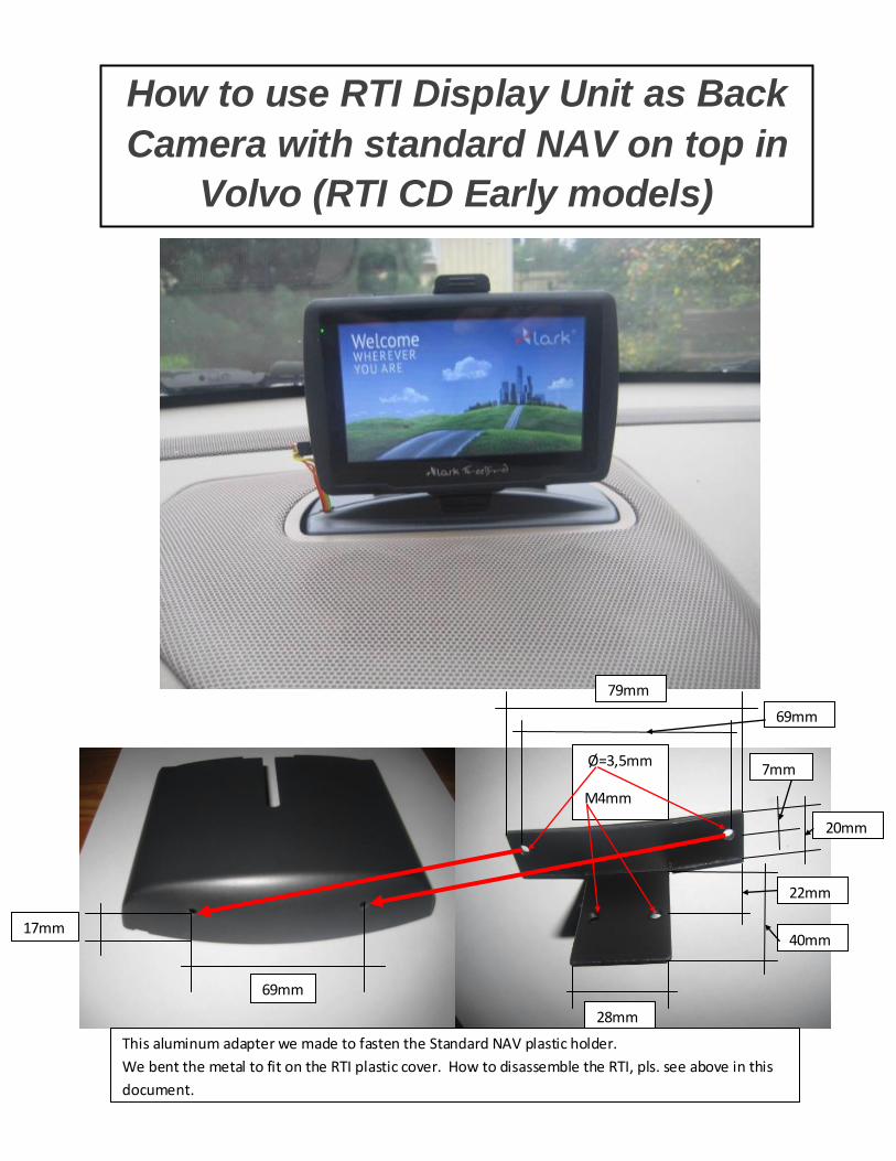
How to use RTI Display Unit as Back
Camera with standard NAV on top in
Volvo (RTI CD Early models)
This aluminum adapter we made to fasten the Standard NAV plastic holder.
We bent the metal to fit on the RTI plastic cover. How to disassemble the RTI, pls. see above in this
document.
69mm
17mm
Ø=3,5mm
M4mm
79mm
28mm
7mm
20mm
22mm
40mm
69mm
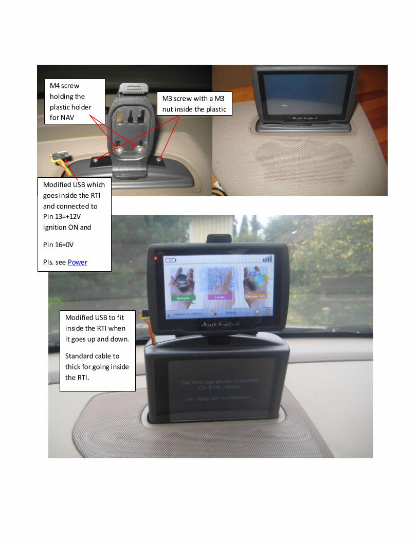
M3 screw with a M3
nut inside the plastic
M4 screw
holding the
plastic holder
for NAV
Modified USB which
goes inside the RTI
and connected to
Pin 13=+12V
ignition ON and
Pin 16=0V
Pls. see Power
Modified USB to fit
inside the RTI when
it goes up and down.
Standard cable to
thick for going inside
the RTI.
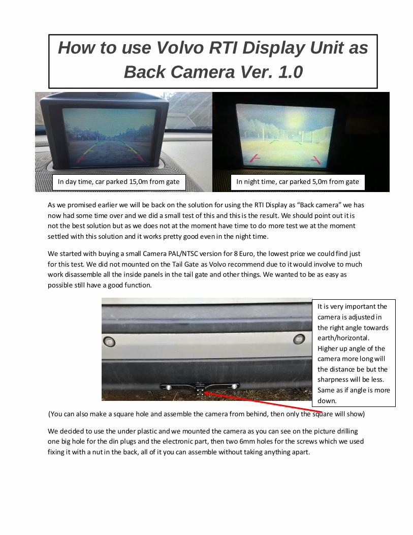
As we promised earlier we will be back on the solution for using the RTI Display as “Back camera” we has
now had some time over and we did a small test of this and this is the result. We should point out it is
not the best solution but as we does not at the moment have time to do more test we at the moment
settled with this solution and it works pretty good even in the night time.
We started with buying a small Camera PAL/NTSC version for 8 Euro, the lowest price we could find just
for this test. We did not mounted on the Tail Gate as Volvo recommend due to it would involve to much
work disassemble all the inside panels in the tail gate and other things. We wanted to be as easy as
possible still have a good function.
(You can also make a square hole and assemble the camera from behind, then only the square will show)
We decided to use the under plastic and we mounted the camera as you can see on the picture drilling
one big hole for the din plugs and the electronic part, then two 6mm holes for the screws which we used
fixing it with a nut in the back, all of it you can assemble without taking anything apart.
How to use RTI Display Unit as Back
Camera
How to use Volvo RTI Display Unit as
Back Camera Ver. 1.0
It is very important the
camera is adjusted in
the right angle towards
earth/horizontal.
Higher up angle of the
camera more long will
the distance be but the
sharpness will be less.
Same as if angle is more
down.
In day time, car parked 15,0m from gate In night time, car parked 5,0m from gate
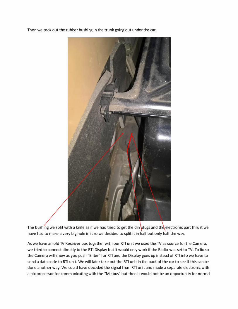
Then we took out the rubber bushing in the trunk going out under the car.
The bushing we split with a knife as if we had tried to get the din plugs and the electronic part thru it we
have had to make a very big hole in it so we decided to split it in half but only half the way.
As we have an old TV Receiver box together with our RTI unit we used the TV as source for the Camera,
we tried to connect directly to the RTI Display but it would only work if the Radio was set to TV. To fix so
the Camera will show as you push “Enter” for RTI and the Display goes up instead of RTI info we have to
send a data code to RTI unit. We will later take out the RTI unit in the back of the car to see if this can be
done another way. We could have decoded the signal from RTI unit and made a separate electronic with
a pic processor for communicating with the “Melbus” but then it would not be an opportunity for normal
people to fix this without huge knowledge of Electronic and Programming and as we try to do something
which everybody can do with little knowledge we decided to use TV for time being.
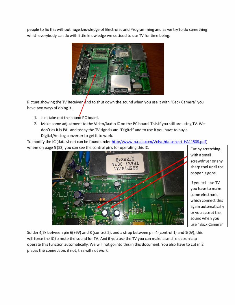
Picture showing the TV Receiver, and to shut down the sound when you use it with “Back Camera” you
have two ways of doing it.
1. Just take out the sound PC board.
2. Make some adjustment to the Video/Audio IC on the PC board. This if you still are using TV. We
don’t as it is PAL and today the TV signals are “Digital” and to use it you have to buy a
Digital/Analog converter to get it to work.
To modify the IC (data sheet can be found under http://www.nasab.com/Volvo/datasheet-HA11508.pdf)
where on page 5 (53) you can see the control pins for operating this IC.
Solder 4,7k between pin 6(+9V) and 8 (control 2), and a strap between pin 4 (control 1) and 1(0V), this
will force the IC to mute the sound for TV. And if you use the TV you can make a small electronic to
operate this function automatically. We will not go into this in this document. You also have to cut in 2
places the connection, if not, this will not work.
Cut by scratching
with a small
screwdriver or any
sharp tool until the
copper is gone.
If you still use TV
you have to make
some electronic
which connect this
again automatically
or you accept the
sound when you
use “Back Camera”
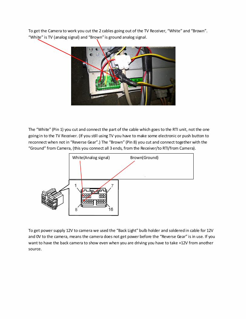
To get the Camera to work you cut the 2 cables going out of the TV Receiver, “White” and “Brown”.
“White” is TV (analog signal) and “Brown” is ground analog signal.
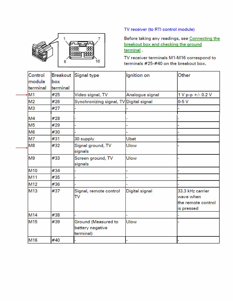
The “White” (Pin 1) you cut and connect the part of the cable which goes to the RTI unit, not the one
going in to the TV Receiver. (If you still using TV you have to make some electronic or push button to
reconnect when not in “Reverse Gear”.) The “Brown” (Pin 8) you cut and connect together with the
“Ground” from Camera, (this you connect all 3 ends, from the Receiver/to RTI/from Camera).
To get power supply 12V to camera we used the “Back Light” bulb holder and soldered in cable for 12V
and 0V to the camera, means the camera does not get power before the “Reverse Gear” is in use. If you
want to have the back camera to show even when you are driving you have to take +12V from another
source.
White(Analog signal) Brown(Ground)
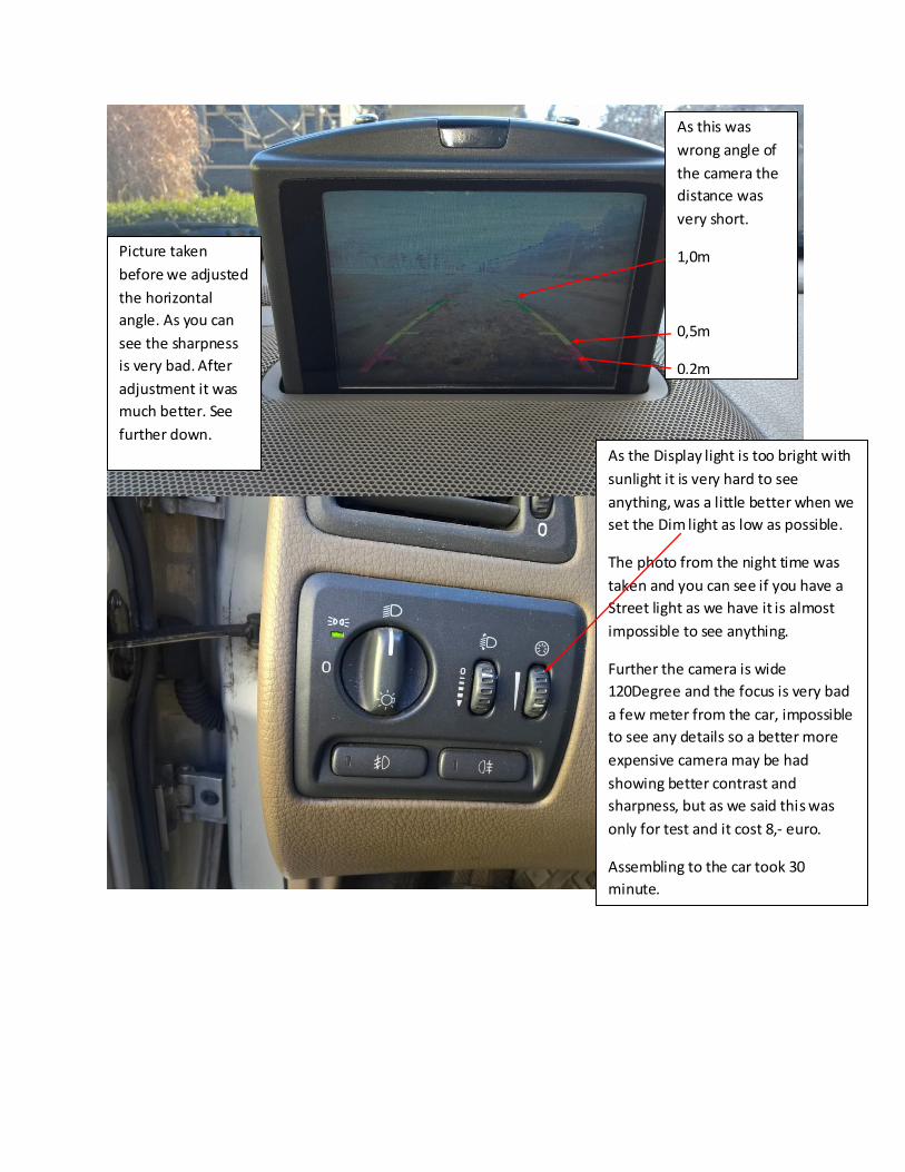
As the Display light is too bright with
sunlight it is very hard to see
anything, was a little better when we
set the Dim light as low as possible.
The photo from the night time was
taken and you can see if you have a
Street light as we have it is almost
impossible to see anything.
Further the camera is wide
120Degree and the focus is very bad
a few meter from the car, impossible
to see any details so a better more
expensive camera may be had
showing better contrast and
sharpness, but as we said this was
only for test and it cost 8,- euro.
Assembling to the car took 30
minute.
Picture taken
before we adjusted
the horizontal
angle. As you can
see the sharpness
is very bad. After
adjustment it was
much better. See
further down.
As this was
wrong angle of
the camera the
distance was
very short.
1,0m
0,5m
0,2m
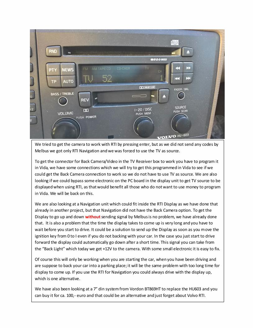
We tried to get the camera to work with RTI by pressing enter, but as we did not send any codes by
Melbus we got only RTI Navigation and we was forced to use the TV as source.
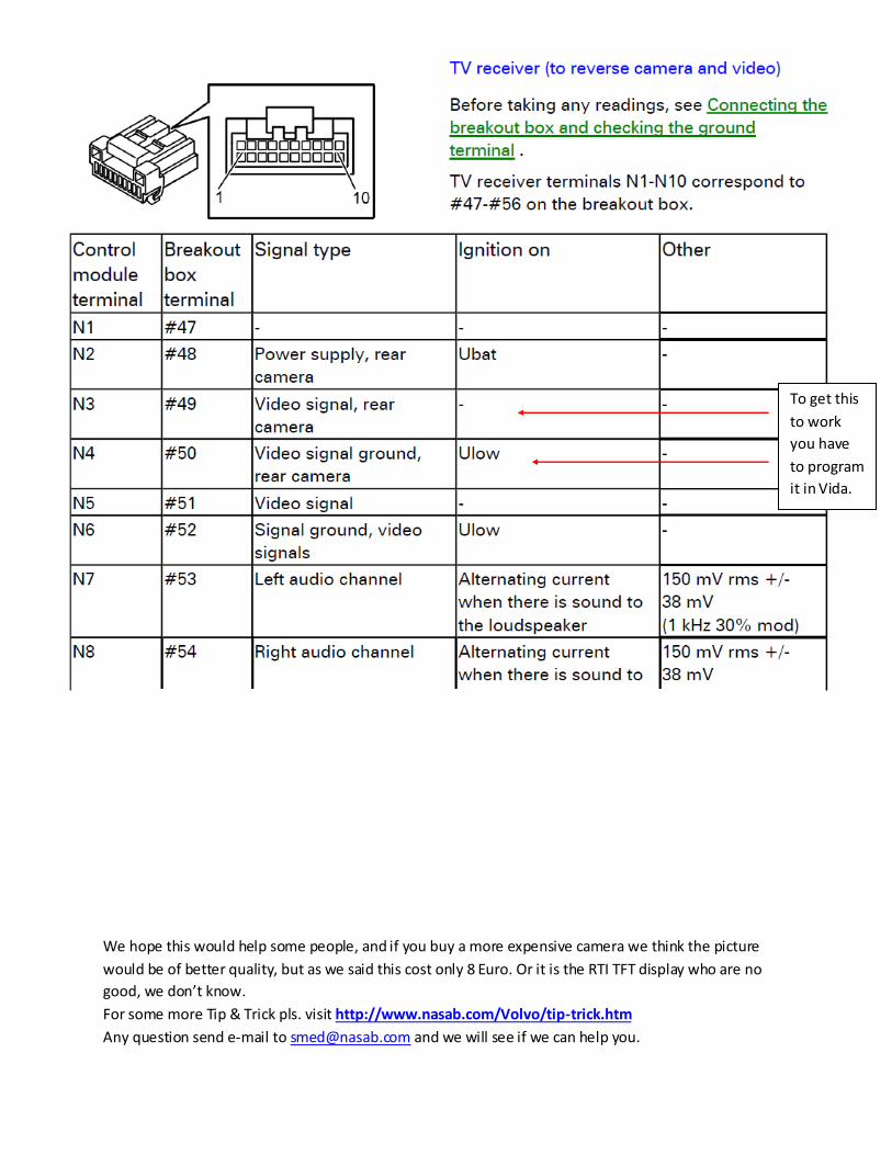
To get the connector for Back Camera/Video in the TV Receiver box to work you have to program it
in Vida, we have some connections which we will try to get this programmed in Vida to see if we
could get the Back Camera connection to work so we do not have to use TV as source. We are also
looking if we could bypass some electronic on the PC board in the display unit to get TV source to be
displayed when using RTI, as that would benefit all those who do not want to use money to program
in Vida. We will be back on this.
We are also looking at a Navigation unit which could fit inside the RTI Display as we have done that
already in another project, but that Navigation did not have the Back Camera option. To get the
Display to go up and down without sending signal by Melbus is no problem, we have already done
that. It is also a problem that the time the display takes to come up is very long and you have to
wait before you start to drive. It could be a solution to send up the Display as soon as you move the
ignition key from 0 to I even if you do not backing with your car. In the case you just start to drive
forward the display could automatically go down after a short time. This signal you can take from
the “Back Light” which today we get +12V to the camera. With some small electronic it is easy to fix.
Of course this will only be working when you are starting the car, when you have been driving and
are suppose to back your car into a parking place; it will be the same problem with too long time for
display to come up. If you use the RTI for Navigation you could always drive with the display up,
which is one alternative.
We have also been looking at a 7” din system from Vordon BT869HT to replace the HU603 and you
can buy it for ca. 100,- euro and that could be an alternative and just forget about Volvo RTI.
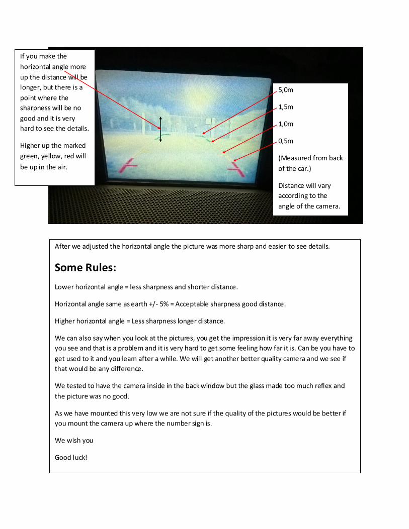
After we adjusted the horizontal angle the picture was more sharp and easier to see details.
Some Rules:
Lower horizontal angle = less sharpness and shorter distance.
Horizontal angle same as earth +/- 5% = Acceptable sharpness good distance.
Higher horizontal angle = Less sharpness longer distance.
We can also say when you look at the pictures, you get the impression it is very far away everything
you see and that is a problem and it is very hard to get some feeling how far it is. Can be you have to
get used to it and you learn after a while. We will get another better quality camera and we see if
that would be any difference.
We tested to have the camera inside in the back window but the glass made too much reflex and
the picture was no good.
As we have mounted this very low we are not sure if the quality of the pictures would be better if
you mount the camera up where the number sign is.
We wish you
Good luck!
5,0m
1,5m
1,0m
0,5m
(Measured from back
of the car.)
Distance will vary
according to the
angle of the camera.
If you make the
horizontal angle more
up the distance will be
longer, but there is a
point where the
sharpness will be no
good and it is very
hard to see the details.
Higher up the marked
green, yellow, red will
be up in the air.
We hope this would help some people, and if you buy a more expensive camera we think the picture
would be of better quality, but as we said this cost only 8 Euro. Or it is the RTI TFT display who are no
good, we don’t know.
For some more Tip & Trick pls. visit http://www.nasab.com/Volvo/tip-trick.htm
Any question send e-mail to [email protected] and we will see if we can help you.
To get this
to work
you have
to program
it in Vida.