s lws en 2 - · pdf filemulti-service active chilled beam mfd. trox understands the art of...
TRANSCRIPT

The art of handling air
Air-water systemsfor air conditioning
Design manual

2
Contents
Experience and innovation 3
Air – water 4
System overview 6
Passive cooling systems 10
Passive chilled beams 13
Chilled ceiling components and elements 18
Induction units 22
Active chilled beams 26
Multi-service active chilled beams 34
Under sill induction units 36
Under floor induction units 40
Façade ventilation units 44
Under sill units 53
Under sill units for projects 54
Under floor units 55
Standards and guidelines 56
Documentation 57
Project management 58
References 59
Design manual | Air-water systems for air conditioning
Multi-service active chilled beam MFD

TROX understands the art of competently handling airlike no other company. Working in close partnership with sophisticated customersall over the world, TROX is the leader in the development,manufacturing, and sale of components and systems forthe air conditioning and ventilation of internal spaces.
The systematic research and development associatedwith individual products continues to expand based onproject specific requirements. With its customer-specificsolutions, TROX sets a trailblazing standard and continuesto enter new markets and maintain sustainable businessopportunities. As a result, TROX, since the introduction ofthe first ceiling mounted chilled beams in the 1980s, hasbeen the leading supplier of these multifaceted productsin Europe.
Products for ventilation and air conditioning technology
TROX CUSTOMER SUPPORTTROX places great value on customer care and providessupport in the design and selection of components andsystems, as well as service and maintenance, during entireproject design, development, and operation phases of aventilation and air conditioning system.
TROX in Figures
- 3,000 employees worldwide
- 380 million € turnover in 2008
- 24 subsidiaries in 22 countries
- 13 production plants in 11 countries
- 11 research and development centres worldwide
- Further more than 25 TROX sales offices and morethan 50 representatives and importers acrossthe globe
TROX has created this design manual to enable you to easily select individual types of air-water systems fora specific application. You will find a general explanationand the advantages of each system, design criteria basedon European standards, economic aspects and an archi -tectural overview.
We wish you satisfaction and success with our newdesign manual.
Share the experience: The art of handling air!
3
The art of handling air
Experience and innovation
Systems• Air-water systems• Laboratory ventilation systems• Communication systems
for fire and smoke protection• High density cooling
solutions for data centres(AITCS)
Components• Air terminal devices• Air terminal units• Fire and smoke protection
components• Sound attenuators• Dampers and
external louvres• Filters and filter elements
Post-Tower, Bonn, Germany
TROX Headquarters, Neukirchen-Vluyn, Germany
The art of handling air

4
In what circumstances shouldair-water systems be used?For many air conditioning tasks, the internal environmentis both contaminated by smells and pollutants and heatedby external and internal thermal loads. Machines, devices,lighting equipment, and even the users of the space cause air contamination and thermal loads, all of which shouldbe taken into consideration during the design. In meetingrooms, cinemas, and theatres, people are the main cause ofair contamination. Good air quality can only be achievedby providing an adequate quantity of clean fresh air thattakes occupancy levels into account. In these cases, therequired heating and cooling capacity is provided by thesupply air temperature differential. Here, a classic airsystem to provide air conditioning is a good choice.
Modern office and administrative buildings are equippedwith a large amount of equipment and often have largeareas of external glazing. The heat emission of the equipment and the solar gain can result in a considerablespace heat load without the air quality being impaired bycontamination.
Space cooling using an all air system would require a highair flow rate resulting in high energy costs for the air distribution system. Here, air-water systems are the idealchoice since the heating and cooling capacity of thesesystems can be provided independent of the required freshair flow rate. In addition, air-water systems have theadvantage that the thermal energy is transported moreefficiently by water than air, this means that water has alower energy requirement to provide the same heating orcooling capacity.
Air – water
Martini church, Bielefeld, GermanyAll air system with jet nozzles
Tholos theatre, Athens, GreeceAll air system with staircase swirl diffusers and jet nozzles
Today, air-water systems are used in many modern buildings and, especially inoffice and administration buildings, offer energy-efficient solutions for the internalspace ventilation and air conditioning. There is a variety of installation possibilitiesfor air-water systems, which means that, for almost every building, variants thatmeet the most demanding architectural requirements are available.
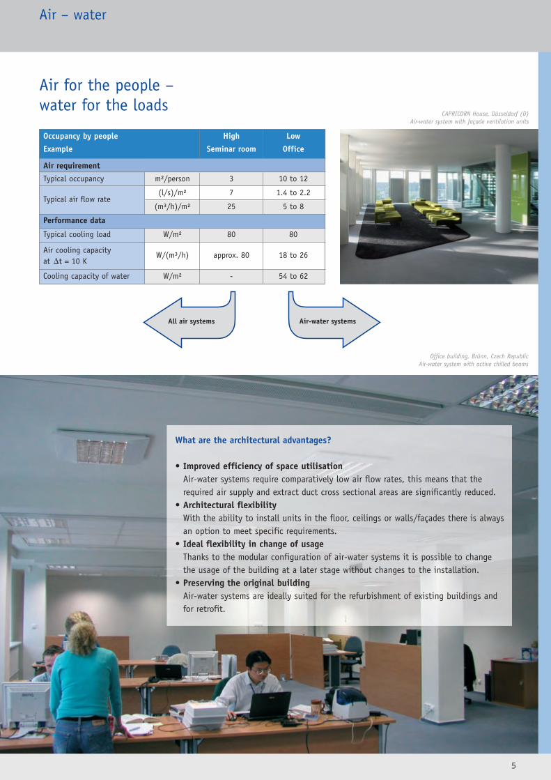
Air for the people – water for the loads
5
What are the architectural advantages?
• Improved efficiency of space utilisationAir-water systems require comparatively low air flow rates, this means that therequired air supply and extract duct cross sectional areas are significantly reduced.
• Architectural flexibilityWith the ability to install units in the floor, ceilings or walls/façades there is alwaysan option to meet specific requirements.
• Ideal flexibility in change of usageThanks to the modular configuration of air-water systems it is possible to changethe usage of the building at a later stage without changes to the installation.
• Preserving the original buildingAir-water systems are ideally suited for the refurbishment of existing buildings andfor retrofit.
Air – water
Occupancy by people High Low
Example Seminar room Office
Air requirement
Typical occupancy m²/person 3 10 to 12
Typical air flow rate(l/s)/m² 7 1.4 to 2.2
(m³/h)/m² 25 5 to 8
Performance data
Typical cooling load W/m² 80 80
Air cooling capacityW/(m³/h) approx. 80 18 to 26
at �t = 10 K
Cooling capacity of water W/m² - 54 to 62
All air systems Air-water systems
CAPRICORN House, Düsseldorf (D)Air-water system with façade ventilation units
Office building, Brünn, Czech RepublicAir-water system with active chilled beams

6
System overview
Passive cooling systems Induction units Façadeventilation units
Page 10 Page 22 Page 44
Passive Chilled ceiling Active Under sill Under floor Under sill Under floorchilled beams components chilled induction induction units unitsand elements beams units units
Page 13 18 26 36 40 53 55
Type of buildingHall •Hotel • • • • •School, university • • •Office, administration • • • • • • •Airport, train station • • •
Installation locationCeiling
Flush-mounted • •Freely suspended • • •
Floor • •Interior wall •External wall/façade • • •
Air diffusionMixed flow • • • • •Displacement flow • • • •
General functionsHeating • • • • • •Cooling • • • • • • •Supply air • • • • •Extract air • • •
Additional functionsLighting • • •Safety • • •Information • • •Sound absorption •Heat recovery • •Latent heat storage • •
Performance data
Typicalcooling capacity 30 – 60 30 – 100 50 – 100 40 – 80 40 – 70 30 – 60 30 – 60
[W/m2]
Typical fresh air flow rate 1.4 – 2.2 1.4 – 2.2 1.4 – 2.2 1.4 – 2.2 1.4 – 2.2[(l/s)/m2]
[(m3/h)/m2] 5 – 8 5 – 8 5 – 8 5 – 8 5 – 8
Typical sound pressurelevel in the space [dB(A)] � 20 � 20 � 35 � 35 � 35 � 35 � 35
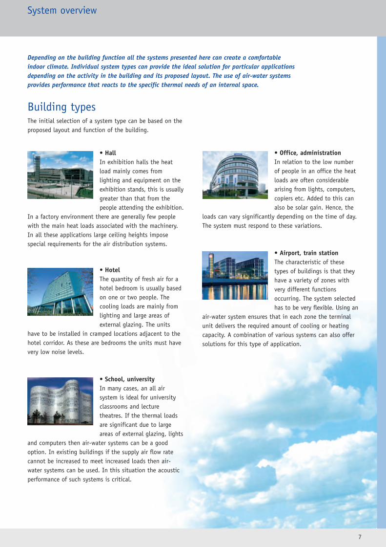
Building typesThe initial selection of a system type can be based on theproposed layout and function of the building.
• HallIn exhibition halls the heatload mainly comes fromlighting and equipment on theexhibition stands, this is usuallygreater than that from the people attending the exhibition.
In a factory environment there are generally few peoplewith the main heat loads associated with the machinery.In all these applications large ceiling heights impose special requirements for the air distribution systems.
• HotelThe quantity of fresh air for ahotel bedroom is usually basedon one or two people. The cooling loads are mainly fromlighting and large areas ofexternal glazing. The units
have to be installed in cramped locations adjacent to thehotel corridor. As these are bedrooms the units must havevery low noise levels.
• School, universityIn many cases, an all airsystem is ideal for universityclassrooms and lecture theatres. If the thermal loadsare significant due to largeareas of external glazing, lights
and computers then air-water systems can be a goodoption. In existing buildings if the supply air flow ratecannot be increased to meet increased loads then air-water systems can be used. In this situation the acousticperformance of such systems is critical.
• Office, administrationIn relation to the low numberof people in an office the heatloads are often considerablearising from lights, computers,copiers etc. Added to this canalso be solar gain. Hence, the
loads can vary significantly depending on the time of day.The system must respond to these variations.
• Airport, train stationThe characteristic of thesetypes of buildings is that theyhave a variety of zones withvery different functions occurring. The system selectedhas to be very flexible. Using an
air-water system ensures that in each zone the terminalunit delivers the required amount of cooling or heatingcapacity. A combination of various systems can also offersolutions for this type of application.
7
System overview
Depending on the building function all the systems presented here can create a comfortableindoor climate. Individual system types can provide the ideal solution for particular applicationsdepending on the activity in the building and its proposed layout. The use of air-water systemsprovides performance that reacts to the specific thermal needs of an internal space.
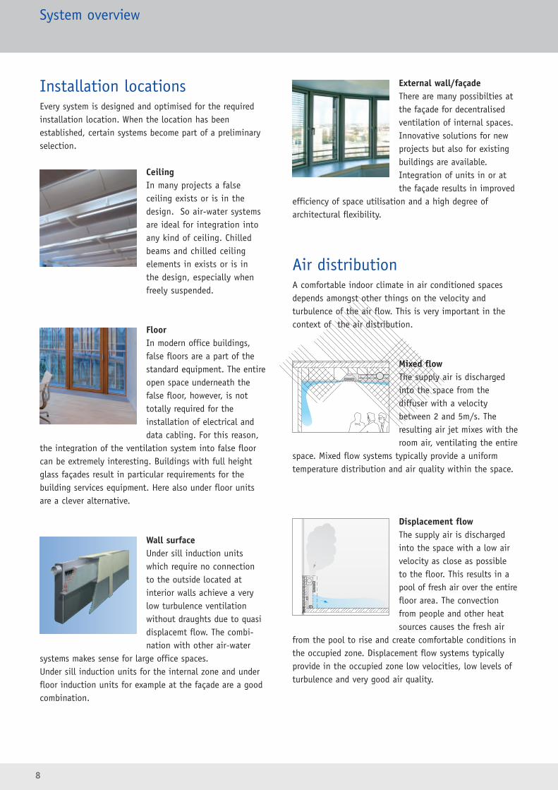
Installation locationsEvery system is designed and optimised for the requiredinstallation location. When the location has been established, certain systems become part of a preliminaryselection.
CeilingIn many projects a false ceiling exists or is in thedesign. So air-water systems are ideal for integration intoany kind of ceiling. Chilledbeams and chilled ceiling elements in exists or is in the design, especially whenfreely suspended.
FloorIn modern office buildings,false floors are a part of thestandard equipment. The entireopen space underneath thefalse floor, however, is nottotally required for the installation of electrical anddata cabling. For this reason,
the integration of the ventilation system into false floorcan be extremely interesting. Buildings with full heightglass façades result in particular requirements for the building services equipment. Here also under floor unitsare a clever alternative.
Wall surfaceUnder sill induction unitswhich require no connectionto the outside located at interior walls achieve a verylow turbulence ventilation without draughts due to quasidisplacemt flow. The combi -nation with other air-water
systems makes sense for large office spaces. Under sill induction units for the internal zone and underfloor induction units for example at the façade are a goodcombination.
External wall/façadeThere are many possibilties atthe façade for decentralisedventilation of internal spaces.Innovative solutions for newprojects but also for existingbuildings are available.Integration of units in or atthe façade results in improved
efficiency of space utilisation and a high degree ofarchitectural flexibility.
Air distributionA comfortable indoor climate in air conditioned spacesdepends amongst other things on the velocity and turbulence of the air flow. This is very important in thecontext of the air distribution.
Mixed flowThe supply air is dischargedinto the space from the diffuser with a velocity between 2 and 5m/s. Theresulting air jet mixes with theroom air, ventilating the entire
space. Mixed flow systems typically provide a uniformtemperature distribution and air quality within the space.
Displacement flowThe supply air is dischargedinto the space with a low airvelocity as close as possible to the floor. This results in apool of fresh air over the entirefloor area. The convectionfrom people and other heatsources causes the fresh air
from the pool to rise and create comfortable conditions inthe occupied zone. Displacement flow systems typicallyprovide in the occupied zone low velocities, low levels ofturbulence and very good air quality.
8
System overview
9
FunctionsThe function of the system is essentially divided into thetype of air handling and subsequent air treatment.
• Façade ventilation units directly provide filtered fresh air to the space. Depending on selection heating and/orcooling can be provided.
• In the case of induction units, the secondary induced air is suitably tempered through either heating or cooling coils.
System overview
Performance dataEssential performance criteria for system selectioninclude the required fresh air flow rate and coolingload. Induction units are supplied by the centralisedair handling system with conditioned fresh air.Façade ventilation units have the shortest possibledistance in which to introduce fresh air from an opening in the wall/façade to the conditioned space.Data on the typical sound pressure level is based ona room attenuation of 6 to 8 dB.
LightingPassive or active chilled beams withintegrated strip lighting or spotlightssave space, increase the quality ofthe installation, and reduce the on-site interfaces.
SafetyPassive and active chilled beams canbe fitted with smoke detectors,sprinklers and motion sensors.Avoiding the installation of theseunits in multiple locations, thusimproving overall building safety.
InformationIntegral loudspeakers, displays, orother optical indicators such as dis-play screens which give people in thebuilding important information, forexample, at train stations or airports.
Sound absorptionChilled ceiling components and elements with sound absorbent material can be used to optimiseroom acoustics and thus increase the comfort levels.
Heat recoveryAn integrated heat recovery improvesthe systems energy efficiency.
Latent heat accumulationIntegration of phase change material(PCM) into the system allows naturalcooling without a refrigeratingmachine using the temperature difference between day and night.
Additional functions
Greater London Authority Building, London, Great Britain

10
Passive cooling systems
Hubert Burda Media Tower, Offenburg, Germany
11
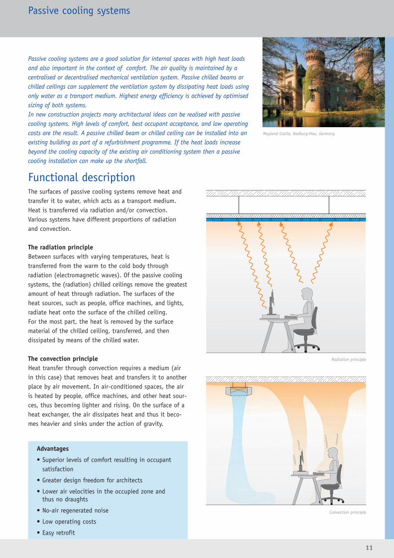
Functional descriptionThe surfaces of passive cooling systems remove heat andtransfer it to water, which acts as a transport medium.Heat is transferred via radiation and/or convection.Various systems have different proportions of radiationand convection.
The radiation principleBetween surfaces with varying temperatures, heat is transferred from the warm to the cold body through radiation (electromagnetic waves). Of the passive coolingsystems, the (radiation) chilled ceilings remove the greatestamount of heat through radiation. The surfaces of theheat sources, such as people, office machines, and lights,radiate heat onto the surface of the chilled ceiling. For the most part, the heat is removed by the surfacematerial of the chilled ceiling, transferred, and then dissipated by means of the chilled water.
The convection principleHeat transfer through convection requires a medium (airin this case) that removes heat and transfers it to anotherplace by air movement. In air-conditioned spaces, the airis heated by people, office machines, and other heat sour-ces, thus becoming lighter and rising. On the surface of aheat exchanger, the air dissipates heat and thus it beco-mes heavier and sinks under the action of gravity.
Passive cooling systems
Passive cooling systems are a good solution for internal spaces with high heat loads and also important in the context of comfort. The air quality is maintained by a centralised or decentralised mechanical ventilation system. Passive chilled beams or chilled ceilings can supplement the ventilation system by dissipating heat loads usingonly water as a transport medium. Highest energy efficiency is achieved by optimisedsizing of both systems. In new construction projects many architectural ideas can be realised with passive cooling systems. High levels of comfort, best occupant acceptance, and low operatingcosts are the result. A passive chilled beam or chilled ceiling can be installed into anexisting building as part of a refurbishment programme. If the heat loads increase beyond the cooling capacity of the existing air conditioning system then a passive cooling installation can make up the shortfall.
Advantages
• Superior levels of comfort resulting in occupantsatisfaction
• Greater design freedom for architects
• Lower air velocities in the occupied zone and thus no draughts
• No-air regenerated noise
• Low operating costs
• Easy retrofit
Moyland Castle, Bedburg-Hau, Germany
Radiation principle
Convection principle

Design informationAir qualityThe passive cooling system only deals with cooling loads.A ventilation or air conditioning system is recommendedto maintain the air quality . The fresh air requirement isusually relatively low (normally 2 to 3 air changes perhour). The ventilation system has the following essentialfunctions:• Fresh air supply for the occupants• Extract of hazardous substances• Control of relative humidity
Thermal output100 % of the thermal performance of passive coolingsystems is produced through heat exchange with chilledwater. The cooling capacity is mainly determined by thedifference between the room temperature and the surfacetemperature of the heat exchanger. The latter depends on the chilled water flow temperature. To increase the performance requires a reduction in water flowtemperature, however, this reduction should not be below the room air dew point to avoid the formationof condensation.
Dew pointIn mechanically ventilated buildings, the humidity of theinside air stays within certain limits, even in summer. At a room temperature of 26°C and 50% relative humidity,the dew point temperature is approximately 15°C. Thus,the chilled water flow temperature for passive cooling systems should be controlled to not fall below 16°C. To be safe, condensation sensors should be used if the chilled water temperature can get close to room dew point.
Open windowsIn the case of opening windows this can result in the humidity in the space rising and hence an increase in roomdew point. The chilled water flow temperature may then be
below the dew point. To avoid this the windows shouldhave contacts that shut off the chilled water flow when the window is opened. From an energy saving standpoint if windows are opened then the air conditioning to thatparticular space should be shut down.
Heating operationNormally, passive cooling systems are optimised for coolingoperation. They can, however, also be used for heating withhot water. A frequent application is heating operation inthe perimeter zone when low external temperatures occur.This provides a means of reducing cold window effects andthus improving the area comfort levels.
• Passive chilled beamsBased on the convection principle, passive chilled beamsheat the layer of air adjacent to the ceiling. With veryhigh hot water temperatures a layer of hot air is generated very close to the ceiling and therefore does not extend to the occupied zone. To avoid this, hot watertemperatures should not exceed 50 °C.
• Chilled ceilingHeat exchange through radiation also starts at the ceiling.On the basis of comfort, hot water flow temperaturesshould not exceed 35 °C. On this basis, there would be amaximum heating capacity of 50 W/m².
ControlAttention must be paid to the control of chilled waterflow temperature in passive cooling systems. The mode of operation and corresponding control depend on thedesign of the system. In all cases the chilled water flowtemperature must not fall below the room dew point. Use of condensation sensors is recommended.
Room temperature controlThe room temperature is controlled using the passive cooling system. The room temperature controller interfaceswith a valve to reduce the chilled water flow rate.The components for chilled water flow and/or room temperature control and water valves can be provided assystem accessories. The product sizing and selectionshould be undertaken in close cooperation with the designteam responsible for the overall building control systems.
12
Passive cooling systems
Swiss Post Office, Chur, Schwitzerland

13
Passive cooling systemsPassive chilled beams
Functional descriptionPassive chilled beams remove the heat from the room airand transfer it to the transport medium water. More than90% of the heat is transferred through convection.As the air passes over the surfaces of the heat exchangeras a result of the cooling, the density of the air increaseshence accelerating the downward air flow. Additionally, as a result of the casing the downward flow is increased further (chimney effect) which in turn again increases thecooling performance.To ensure adequate airflow through the passive chilledbeam it is usually free hanging below the ceiling, however, flush installation is an option providing suitablegaps are incorporated in the ceiling to allow adequate air flow to the beam.
Passive chilled beams dissipate large heat loads and are suited for a wide spectrum ofapplications and requirements. In combination with ventilation or air conditioningsystems, they deal with the largest portion of the heat load. They can also be used as an effective supplement to all air or other air-water systems to provide additionalcooling capacity.Passive chilled beams do not require false ceilings and are thus an excellent choice forrefurbishment and retrofit projects.Multi-service passive chilled beams are complete building service solutions that havefurther functional elements in addition to air handling technology. Hubert Burda Media Tower, Offenburg, Germany
Advantages
• Passive chilled beams are able to deal with largethermal loads within a space
• Installation into a ceiling results in a very flexibledesign for office areas
• Specific layout and partitioning arrangements can beaccommodated
• Cooling system does not generate any noise
• The units available offer a variety of sizes providinga range of performance from low to high capacity
• Freely suspended, concealed, or flush ceilingmounting
• Multi-service functions possible
• Suitable for refurbishment projects
Düsseldorf Airport, Düsseldorf, Germany
Passive chilled beam section

14
Multi-service capabilityLike active chilled beams, passive chilled beams can fulfiladditional functions. The factory installation of wiring andcomponent piping results in a product that has a „plug andplay“ facility when installed on site. This minimises therequired site time for installation and commissioning.
• Integrated light fittings with various lighting systemperformance options
• Smoke detectors• Sprinklers• Loudspeakers• Motion detectors• Hidden integral cable trays
Design informationDesignPassive chilled beams are designed in such a way that theycan be harmoniously integrated into the ceiling’s visualdesign. The dimensions are compatible with conventionalceiling systems. When freely suspended, the passive chilledbeams can provide a striking visual element of the interiordesign.If the passive chilled beams are used in conjunction witha grid ceiling system, the room layout below is flexibleand can be altered at a later date.
Air distributionDepending on the product design there is a downward flowof cooled air below a passive chilled beam. In the case oflarge cooling capacity, discharge velocities of greater than0.2m/s can occur below the chilled beam. This can be anissue with respect to the occupied zone depending onroom height. In these situations chilled beams should belocated in the aisle or corridor areas rather than directlyabove work stations. Installations on the building peri -meter can have the advantage in summer of utilising theup currents on the inside of the glazing to enhance theperformance of the beam as well as improving the localenvironmental comfort.In the case of passive chilled beams that are sized formoderate levels of cooling, the specific location above theoccupied zone is not critical.
Control valves andactuators
Lights and cabletrays
Loudspeakers
Water pipes
Sprinklers
Passive cooling systemsPassive chilled beams
Royal Bank of Scotland Headquarters, Gogarburn, Great Britain

15
Installation into various ceiling systemsPassive chilled beams are uniquely suited to use with all ceiling systems. The main issue is to ensure that thereis a relatively unobstructed path for the airflow to the passive chilled beam inlet.
• Freely suspendedFreely suspended installation is possible for all types ofceiling system.
• Flush-mounted in grid ceilingsThe installation of a passive chilled ceiling is independent of the adjacent false ceiling. It is essential that there are gaps between the ceilingtiles around the beams to ensure adequate airflow intothe beam inlet. The total free area required should be the size (L x W) of the chilled beam inlet.
• Open grid ceilingsThe passive chilled beam is freely suspended above theceiling grid. The openings of the open grid ceiling aresufficient to ensure free air movement into the voidabove.
• Continuous false ceilingsFlush ceiling installation into continuous false ceilingswithout adjacent gaps for air flow to the beam is alsopossible. However, in this case a return air path to thepassive chilled beam inlet must be provided by a returnair diffuser or perforated plate or an adequate gap between the wall and the false ceiling.
Limitations of use• If the passive chilled beam is installed directly above a work
station, the cooling capacity should not exceed 150 W/m.
In case of higher capacities, locations directly underneath
may become draughty.
• In comfort conditioning, adequate indoor air quality can
only be achieved by using a fresh air ventilation system in
conjunction with passive chilled beams.
• An opening window system for ventilation should not be used
as when the external humidity is high this can result in
condensation occurring on the chilled surfaces.
• In adjacent rooms without mechanical ventilation, passive
chilled beams should only be used if there is no potential
for high levels of moisture otherwise there is a risk of
condensation.
• The maximum heating capacity can be up to approx. 150 W/m.
Passive cooling systemsPassive chilled beams
Norwich Union Headquarters, Norwich, Great Britain
16
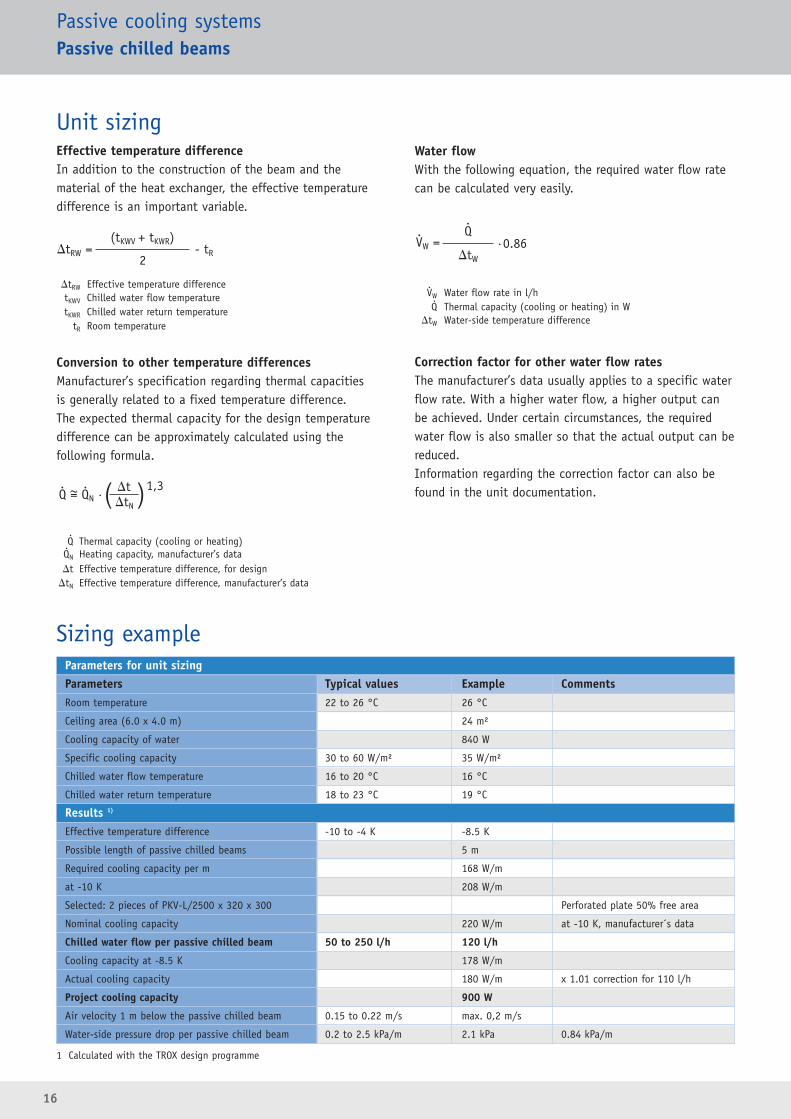
Parameters for unit sizing Parameters Typical values Example CommentsRoom temperature 22 to 26 °C 26 °C
Ceiling area (6.0 x 4.0 m) 24 m²
Cooling capacity of water 840 W
Specific cooling capacity 30 to 60 W/m² 35 W/m²
Chilled water flow temperature 16 to 20 °C 16 °C
Chilled water return temperature 18 to 23 °C 19 °C
Results 1)
Effective temperature difference -10 to -4 K -8.5 K
Possible length of passive chilled beams 5 m
Required cooling capacity per m 168 W/m
at -10 K 208 W/m
Selected: 2 pieces of PKV-L/2500 x 320 x 300 Perforated plate 50% free area
Nominal cooling capacity 220 W/m at -10 K, manufacturer´s data
Chilled water flow per passive chilled beam 50 to 250 l/h 120 l/h
Cooling capacity at -8.5 K 178 W/m
Actual cooling capacity 180 W/m x 1.01 correction for 110 l/h
Project cooling capacity 900 W
Air velocity 1 m below the passive chilled beam 0.15 to 0.22 m/s max. 0,2 m/s
Water-side pressure drop per passive chilled beam 0.2 to 2.5 kPa/m 2.1 kPa 0.84 kPa/m
Passive cooling systemsPassive chilled beams
Sizing example
Unit sizing Effective temperature differenceIn addition to the construction of the beam and the material of the heat exchanger, the effective temperaturedifference is an important variable.
�tRW Effective temperature differencetKWV Chilled water flow temperaturetKWR Chilled water return temperature
tR Room temperature
Conversion to other temperature differencesManufacturer’s specification regarding thermal capacitiesis generally related to a fixed temperature difference. The expected thermal capacity for the design temperaturedifference can be approximately calculated using the following formula.
Q Thermal capacity (cooling or heating)QN Heating capacity, manufacturer’s data�t Effective temperature difference, for design
�tN Effective temperature difference, manufacturer’s data
Water flowWith the following equation, the required water flow ratecan be calculated very easily.
VW Water flow rate in l/hQ Thermal capacity (cooling or heating) in W
�tW Water-side temperature difference
Correction factor for other water flow ratesThe manufacturer’s data usually applies to a specific waterflow rate. With a higher water flow, a higher output canbe achieved. Under certain circumstances, the requiredwater flow is also smaller so that the actual output can bereduced.Information regarding the correction factor can also befound in the unit documentation.
�tRW =(tKWV + tKWR)
- tR2
..
..
1 Calculated with the TROX design programme
Q = QN ·1,3
�tN
�t. .~ ( )
VW =Q
·0.86�tW
..
17
Passive cooling systemsPassive chilled beams
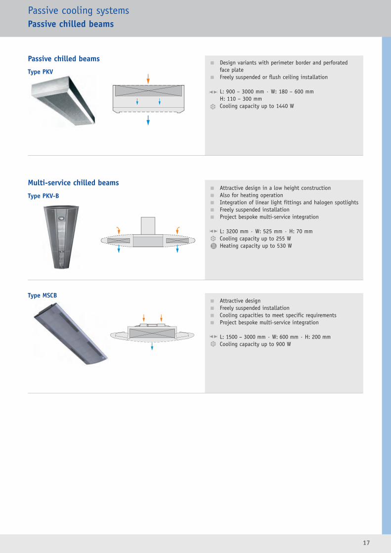
Type PKV� Design variants with perimeter border and perforated
face plate� Freely suspended or flush ceiling installation
L: 900 – 3000 mm · W: 180 – 600 mm H: 110 – 300 mmCooling capacity up to 1440 W
Passive chilled beams
Type PKV-B� Attractive design in a low height construction� Also for heating operation� Integration of linear light fittings and halogen spotlights� Freely suspended installation� Project bespoke multi-service integration
L: 3200 mm · W: 525 mm · H: 70 mm Cooling capacity up to 255 WHeating capacity up to 530 W
Multi-service chilled beams
Type MSCB� Attractive design� Freely suspended installation� Cooling capacities to meet specific requirements� Project bespoke multi-service integration
L: 1500 – 3000 mm · W: 600 mm · H: 200 mmCooling capacity up to 900 W
18
Passive cooling systemsChilled ceilings · Components and elements
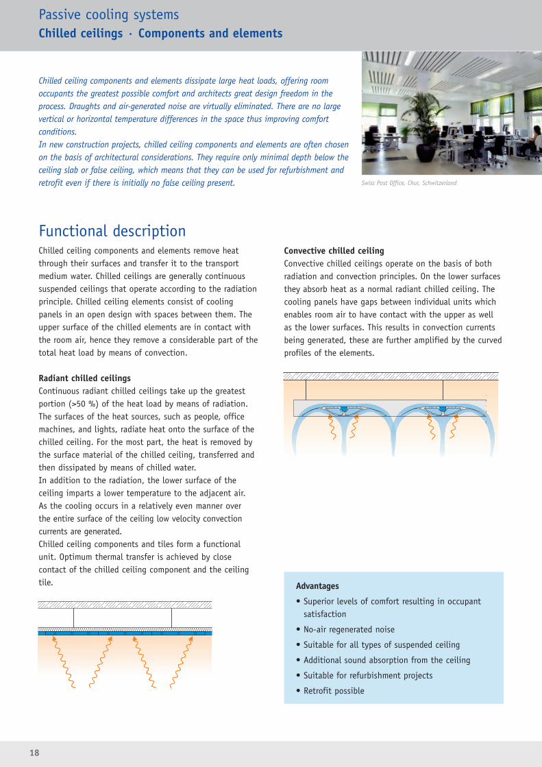
Functional descriptionChilled ceiling components and elements remove heatthrough their surfaces and transfer it to the transportmedium water. Chilled ceilings are generally continuoussuspended ceilings that operate according to the radiationprinciple. Chilled ceiling elements consist of coolingpanels in an open design with spaces between them. Theupper surface of the chilled elements are in contact withthe room air, hence they remove a considerable part of thetotal heat load by means of convection.
Radiant chilled ceilingsContinuous radiant chilled ceilings take up the greatestportion (>50 %) of the heat load by means of radiation.The surfaces of the heat sources, such as people, officemachines, and lights, radiate heat onto the surface of thechilled ceiling. For the most part, the heat is removed bythe surface material of the chilled ceiling, transferred andthen dissipated by means of chilled water.In addition to the radiation, the lower surface of the ceiling imparts a lower temperature to the adjacent air. As the cooling occurs in a relatively even manner over the entire surface of the ceiling low velocity convection currents are generated.Chilled ceiling components and tiles form a functionalunit. Optimum thermal transfer is achieved by close contact of the chilled ceiling component and the ceilingtile.
Convective chilled ceilingConvective chilled ceilings operate on the basis of bothradiation and convection principles. On the lower surfacesthey absorb heat as a normal radiant chilled ceiling. Thecooling panels have gaps between individual units whichenables room air to have contact with the upper as wellas the lower surfaces. This results in convection currentsbeing generated, these are further amplified by the curvedprofiles of the elements.
Chilled ceiling components and elements dissipate large heat loads, offering room occupants the greatest possible comfort and architects great design freedom in theprocess. Draughts and air-generated noise are virtually eliminated. There are no largevertical or horizontal temperature differences in the space thus improving comfort conditions.In new construction projects, chilled ceiling components and elements are often chosenon the basis of architectural considerations. They require only minimal depth below theceiling slab or false ceiling, which means that they can be used for refurbishment andretrofit even if there is initially no false ceiling present.
Advantages
• Superior levels of comfort resulting in occupantsatisfaction
• No-air regenerated noise
• Suitable for all types of suspended ceiling
• Additional sound absorption from the ceiling
• Suitable for refurbishment projects
• Retrofit possible
Swiss Post Office, Chur, Schwitzerland
19
Passive cooling systemsChilled ceilings · Components and elements
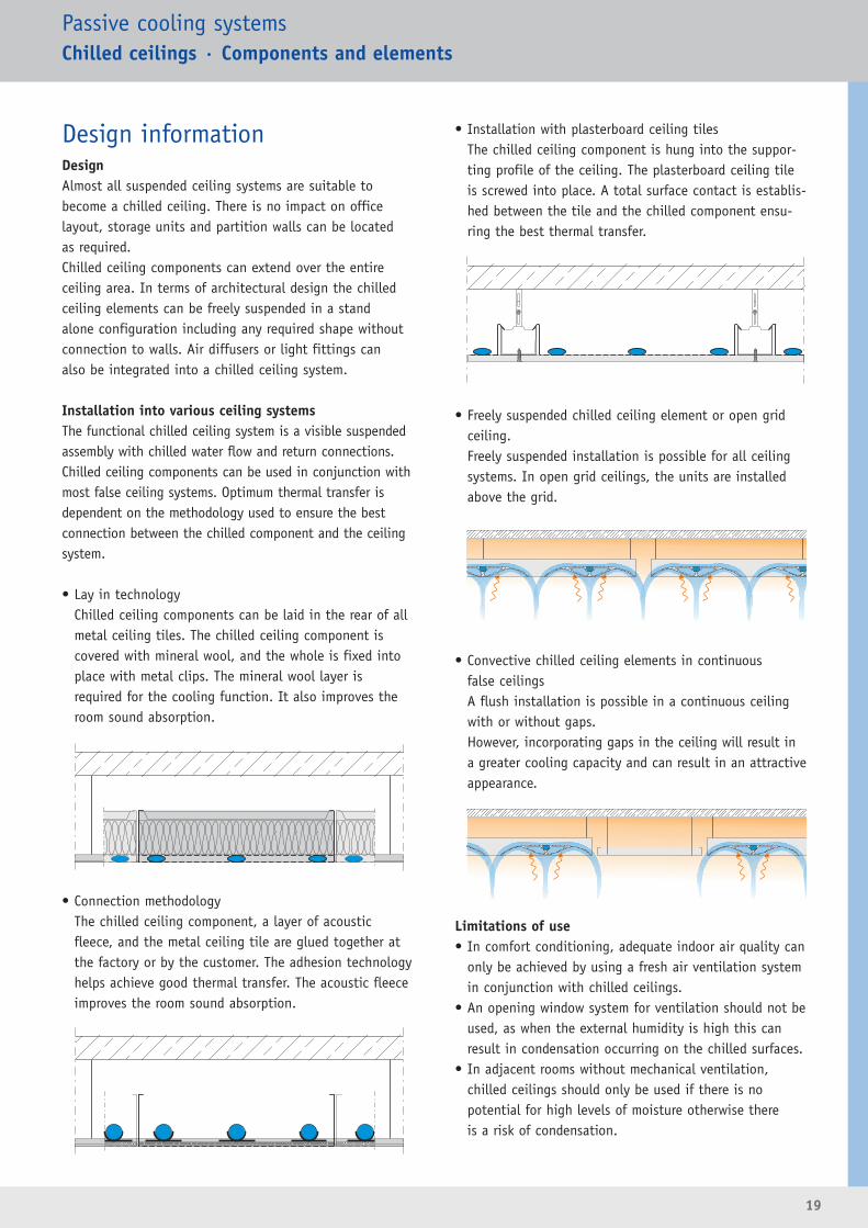
Design informationDesignAlmost all suspended ceiling systems are suitable tobecome a chilled ceiling. There is no impact on office layout, storage units and partition walls can be located as required.Chilled ceiling components can extend over the entire ceiling area. In terms of architectural design the chilledceiling elements can be freely suspended in a stand alone configuration including any required shape without connection to walls. Air diffusers or light fittings can also be integrated into a chilled ceiling system.
Installation into various ceiling systemsThe functional chilled ceiling system is a visible suspendedassembly with chilled water flow and return connections.Chilled ceiling components can be used in conjunction withmost false ceiling systems. Optimum thermal transfer isdependent on the methodology used to ensure the bestconnection between the chilled component and the ceilingsystem.
• Lay in technologyChilled ceiling components can be laid in the rear of allmetal ceiling tiles. The chilled ceiling component iscovered with mineral wool, and the whole is fixed intoplace with metal clips. The mineral wool layer is required for the cooling function. It also improves theroom sound absorption.
• Connection methodologyThe chilled ceiling component, a layer of acousticfleece, and the metal ceiling tile are glued together atthe factory or by the customer. The adhesion technologyhelps achieve good thermal transfer. The acoustic fleeceimproves the room sound absorption.
• Installation with plasterboard ceiling tilesThe chilled ceiling component is hung into the suppor-ting profile of the ceiling. The plasterboard ceiling tileis screwed into place. A total surface contact is establis-hed between the tile and the chilled component ensu-ring the best thermal transfer.
• Freely suspended chilled ceiling element or open gridceiling.Freely suspended installation is possible for all ceilingsystems. In open grid ceilings, the units are installedabove the grid.
• Convective chilled ceiling elements in continuousfalse ceilingsA flush installation is possible in a continuous ceilingwith or without gaps.However, incorporating gaps in the ceiling will result in a greater cooling capacity and can result in an attractive appearance.
Limitations of use• In comfort conditioning, adequate indoor air quality can
only be achieved by using a fresh air ventilation systemin conjunction with chilled ceilings.
• An opening window system for ventilation should not beused, as when the external humidity is high this canresult in condensation occurring on the chilled surfaces.
• In adjacent rooms without mechanical ventilation, chilled ceilings should only be used if there is nopotential for high levels of moisture otherwise there is a risk of condensation.

20
Passive cooling systemsChilled ceilings · Components and elements
Parameters for unit sizingParameters Typical values Example CommentsRoom temperature 22 to 26 °C 26 °C
Ceiling area 50 m²
Cooling capacity of water 2250 W
Specific cooling capacity 30 to 100 W/m² 45 W/m²
Chilled water flow temperature 16 to 20 °C 18 °C
Chilled water return temperature 18 to 23 °C 20 °C
Results 1)
Effective temperature difference -10 to -4 K -7 K
Nominal cooling capacity 50 to 90 W/m²
Manufacturer’s data 70 W/m² at -8 K
Cooling capacity at -7 K 60 W/m²
Required area 38 m² 2250 W / 61 (W/m²)
Active area 60 to 80 % 76 % 38 m² / 50 m²
Increase in capacity 5 % manufacturer’s data
Active chilled ceiling area 35 m² 38 m² / 1.05
Chilled water flow 968 l/h
Sizing example
Unit sizing Effective temperature differenceIn addition to the construction and material of the chilled ceiling, the effective temperature difference is an important variable.
�tRW Effective temperature differencetKWV Chilled water flow temperaturetKWR Chilled water return temperature
tR Room temperature
Conversion to other temperature differencesManufacturer’s specification regarding thermal capacity isgenerally related to a fixed temperature difference. Theexpected thermal capacity for the design temperature dif-ference can be approximately calculated using the following formula.
Q Thermal capacity (cooling or heating)QN Heating capacity, manufacturer’s data�t Effective temperature difference, for design
�tN Effective temperature difference, manufacturer’s data* related to type of ceiling
Water flowWith the following equation, the required water flow ratecan be calculated very easily.
VW Water flow rate in l/hQ Thermal capacity (cooling or heating) in W
�tW Water-side temperature difference
Correction factor for other water flow ratesThe manufacturer’s data usually applies to a fixed waterflow rate. With a higher water flow, a higher output canbe achieved. Under certain circumstances, the requiredwater flow is also smaller so that the actual output canbe reduced.Information regarding the correction factor can also befound in the unit documentation.
Increase of capacityAn increase of capacity will occur when the chilled ceilingcomponents are not covered with mineral fibre. The complete void is then chilled and even other ceiling areashave a chilling effect.Values for the increase of capacity are available from themanufacturer.
..
..
1 Calculated with the TROX design programme
�tRW =(tKWV + tKWR)
- tR2
VW =Q
·0.86�tW
..
Q = QN ·1.1*
�tN
�t. .~ ( )
21
Passive cooling systemsChilled ceilings · Components and elements
Type WK-D-UM
Type WK-D-WF
Type WK-D-UG
Type WK-D-EL
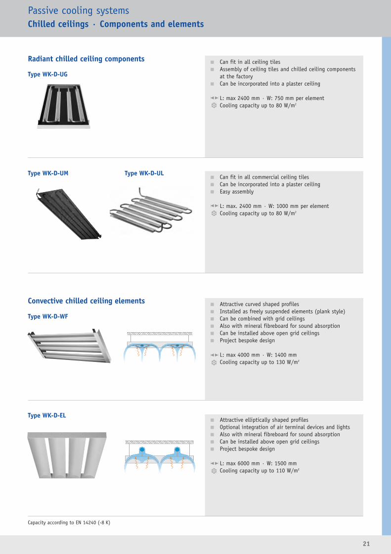
Radiant chilled ceiling components
Convective chilled ceiling elements
Type WK-D-UL
� Can fit in all ceiling tiles� Assembly of ceiling tiles and chilled ceiling components
at the factory� Can be incorporated into a plaster ceiling
L: max 2400 mm · W: 750 mm per elementCooling capacity up to 80 W/m2
� Can fit in all commercial ceiling tiles� Can be incorporated into a plaster ceiling� Easy assembly
L: max. 2400 mm · W: 1000 mm per elementCooling capacity up to 80 W/m2
� Attractive curved shaped profiles� Installed as freely suspended elements (plank style)� Can be combined with grid ceilings� Also with mineral fibreboard for sound absorption� Can be installed above open grid ceilings� Project bespoke design
L: max 4000 mm · W: 1400 mm Cooling capacity up to 130 W/m2
� Attractive elliptically shaped profiles� Optional integration of air terminal devices and lights� Also with mineral fibreboard for sound absorption� Can be installed above open grid ceilings� Project bespoke design
L: max 6000 mm · W: 1500 mm Cooling capacity up to 110 W/m2
Capacity according to EN 14240 (-8 K)

22
Induction units
Chambre de Commerce, Luxembourg
23
Induction units
The induction principleThe laws of aerodynamics for a free jet provide the basisfor the induction principle.
Air discharging into a large space acts as a free jet. At thepoint of discharge the cross-sectional area defines theflow rate, its velocity and direction of discharge. Aroundthe boundary of a free jet the interaction with the air inthe room results in acceleration of the adjacent local air.This air is induced into the jet thus increasing the totalmoving air flow. Since the induced air has to be accelerated
the resultant total volume of air moving slows down. This process continues until the overall air velocity falls to zero.
The discharge from every type of air terminal deviceresults in the induction process with the room air.Horizontal discharge from the air terminal device causesthe flow to continue along the ceiling surface. Hence, the induction process can only take place on the lower exposed part of the jet, this then occurs across the entireroom.In the case of induction units the induction process takesplace inside the unit. The design is such that the induced(secondary) air passes through a heat exchanger. The freshair and the secondary air, which has been heated/cooledas required, together are discharged back into the space.At the same fresh air supply flow rate the induction process results in a much higher thermal capacity than a diffuser system just supplying conditioned air from central plant.
Advantages• Good acoustic and flow characteristics provide
excellent comfort
• The fresh air flow rate can be selected to create anair quality conducive to good health
• The fresh air volume flow rate is generally constant
• The fresh air volume flow rate is only a third of thatof an all air system
• A large percentage of the thermal load is dissipatedwith water
• Economic combination of air diffuser and water cooling system
• No additional fans to provide the secondary air
• Excellent assimilation into the interior design:– Harmonious integration in walls, ceilings, or floors– Freely suspended units as a design feature
• Reduction in space required for the air distributionsystem due to smaller plant rooms and ductingsystems and low overall heights of the induction units
• Independent heating and cooling operation can beprovided in adjacent rooms
• Additional provision of static heating systems maynot be necessary
• No moving parts, resulting in operational reliabilityand low maintenance
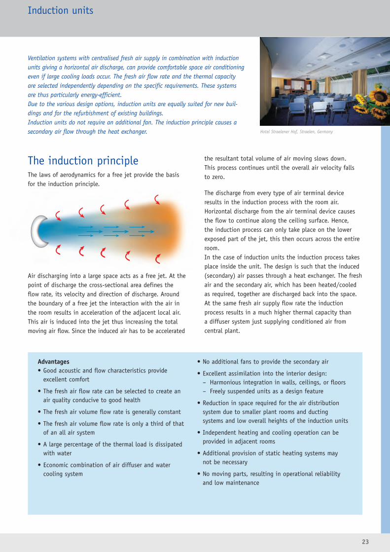
Ventilation systems with centralised fresh air supply in combination with inductionunits giving a horizontal air discharge, can provide comfortable space air conditioningeven if large cooling loads occur. The fresh air flow rate and the thermal capacityare selected independently depending on the specific requirements. These systemsare thus particularly energy-efficient.Due to the various design options, induction units are equally suited for new buil-dings and for the refurbishment of existing buildings.Induction units do not require an additional fan. The induction principle causes asecondary air flow through the heat exchanger. Hotel Straelener Hof, Straelen, Germany
24
Induction units
Design informationOutdoor air flow rateTo achieve a good indoor air quality, centrally conditionedfresh air is supplied to the space. The required amount offresh air primarily depends on the number of people.In case of very high thermal loads, however, a higher freshair flow rate may be necessary so that the required capacitycan be achieved.
Thermal capacityThe thermal capacity of induction units is the sum of the capacity of the fresh air and the capacity provided bythe heat exchanger. The air flow rate and temperature of the fresh air are defi-ned variables from which a certain capacity is calculated.The capacity of the heat exchanger is determined by theflow temperature of the water on the one hand and the airand water flow rate on the other. As the induction increases, the total air flow rate increasesand thus so does the thermal capacity. For a unit and heat exchanger of fixed dimensions the useof different size nozzles can alter the thermal capacity.Higher levels of induction are only achieved with highernozzle pressures and thus higher noise levels.
Dew pointIn many cases, cooling operation with induction units takes place
using dry (sensible) cooling. On the one hand, the humidity
remains under control due to the air conditioning of the space,
while, on the other hand, the flow temperature of the chilled
water is controlled to an offset value above the dew point tempe-
rature of the room air. A dry operation of the units is thus guaran-
teed.
High cooling capacities can be achieved with wet (latent) cooling.
The chilled water flow temperature in this case lies below the dew
point, with the result that condensate forms in the heat
exchanger. A condensate drip tray beneath the heat exchanger is
essential in this case.
Even in regions that tend to have high humidity (tropics,
subtropics), only units with a condensate drip tray should be con-
sidered in the design process.
Open windowsIn the case of opening windows, this can result in the humidity in
the space rising and hence an increase in room dew point. The
chilled water flow temperature may then be below the dew point.
To avoid this, the windows should have contacts that shut off the
chilled water flow when the window is opened. From an energy
saving standpoint, if windows are opened then the air conditioning
(heating or cooling) to that particular space should be shut down.
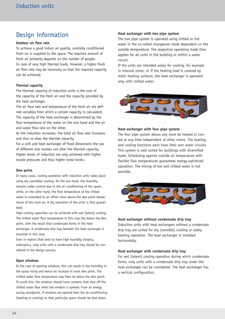
Heat exchanger with two pipe systemThe two pipe system is operated using chilled or hotwater in the so-called changeover mode dependent on theoutside temperature. The respective operating mode thenapplies for all units in the building or within a water circuit. If the units are intended solely for cooling, for example in internal zones, or if the heating load is covered by static heating surfaces, the heat exchanger is operatedonly with chilled water.
Heat exchanger with four pipe system The four pipe system allows any room be heated or coo-led at any time independent of other rooms. The heatingand cooling functions each have their own water circuits.This system is well suited for buildings with diversifiedloads. Scheduling against outside air temperature with flexible flow temperatures guarantees energy-optimisedoperation. The mixing of hot and chilled water is not possible.
Heat exchanger without condensate drip trayInduction units with heat exchangers without a condensatedrip tray are suited for dry (sensible) cooling or solely heating operation. The heat exchanger is installed horizontally.
Heat exchanger with condensate drip trayFor wet (latent) cooling operation during which condensateforms, only units with a condensate drip tray under theheat exchanger can be considered. The heat exchanger hasa vertical configuration.

25
Induction units
Room temperatureA room temperature controllercontrols the capacity of the heatexchanger using water valves. Forfour pipe systems the room tem-perature controller has to havetwo outputs one for heating one for cooling. Two pipe systemshave room temperature control-
lers with one output, possibly with a changeover function. The control function can be implemented using electronicroom temperature controllers or direct digital control(DDC) technology.
The components for adjusting or controlling the flow rate,room temperature controllers and water valves, can beinstalled at the factory and provided pre-wired as systemaccessories. The product selection and sizing should takeplace in close cooperation with the project participantsresponsible for the building management systems.
ControlConditioned fresh air flow rateInduction units are generally operated with constant fresh air. Balancingdampers or flow rate controllers are used to distribute the required air flowrate to several units.
Balancing dampersCommissioning is very time-consuming since the flowrate has to be measured andadjusted several times on allunits.
Volume flow limitersCommissioning can be carriedout quickly and easily. Therequired flow rate value isset and the volume flow limiter is inserted into theduct.
System-powered controllersThe flow rate setpoint value isadjusted using an external scale.Further adjustment tasks are notrequired. Subsequent changes inthe setpoint value can be easilyachieved.
Variable air volume controllersThe fresh air flow rate is controlled using electrical orpneumatic auxiliary power.Variable volume control or day/night changeover is possible.Flow rate controllers also makesense when the air flow rateneeds to be shut off or theactual flow rate needs to be provided as a voltage signal.
26
Induction unitsActive Chilled Beams
Advantages• Active chilled beams are able to ventilate spaces
with large thermal loads without draughts.
• High level of flexibility of office layout due tohorizontal air discharge
• Storage units and partition walls can be located as required
• Unit types with a range of sizes to provide thermalperformance levels from low to high
• Larger units with high performance can be installed in the ceiling
• Often the only possibility for refurbishment ofexisting air distribution systems in false ceilingswith low void depth
• Low height units offer advantages for both refurbishment and new build projects
Functional descriptionActive chilled beams supply fresh air to the space from acentral plant room to maintain indoor air quality whilstproviding cooling and/or heating using heat exchangers.
The fresh air is discharged into the beam mixing chambervia nozzles. As a result of this secondary air is induced viaan inlet grille and then passes through heat exchangersinto the mixing chamber. Here it is mixed with the freshair and the total supply air is discharged horizontally intothe space through integral slot diffusers.
The horizontal discharge into the space results in a“mixed flow” air distribution. The slot diffuser dischargevelocity is selected such that the supply air penetratesinto the occupied zone to maintain the air quality in thespace without creating draughts. Due to induction of roomair into the supply air stream in the space, the tempera-ture differential in the air stream reduces and its velocitydecreases.
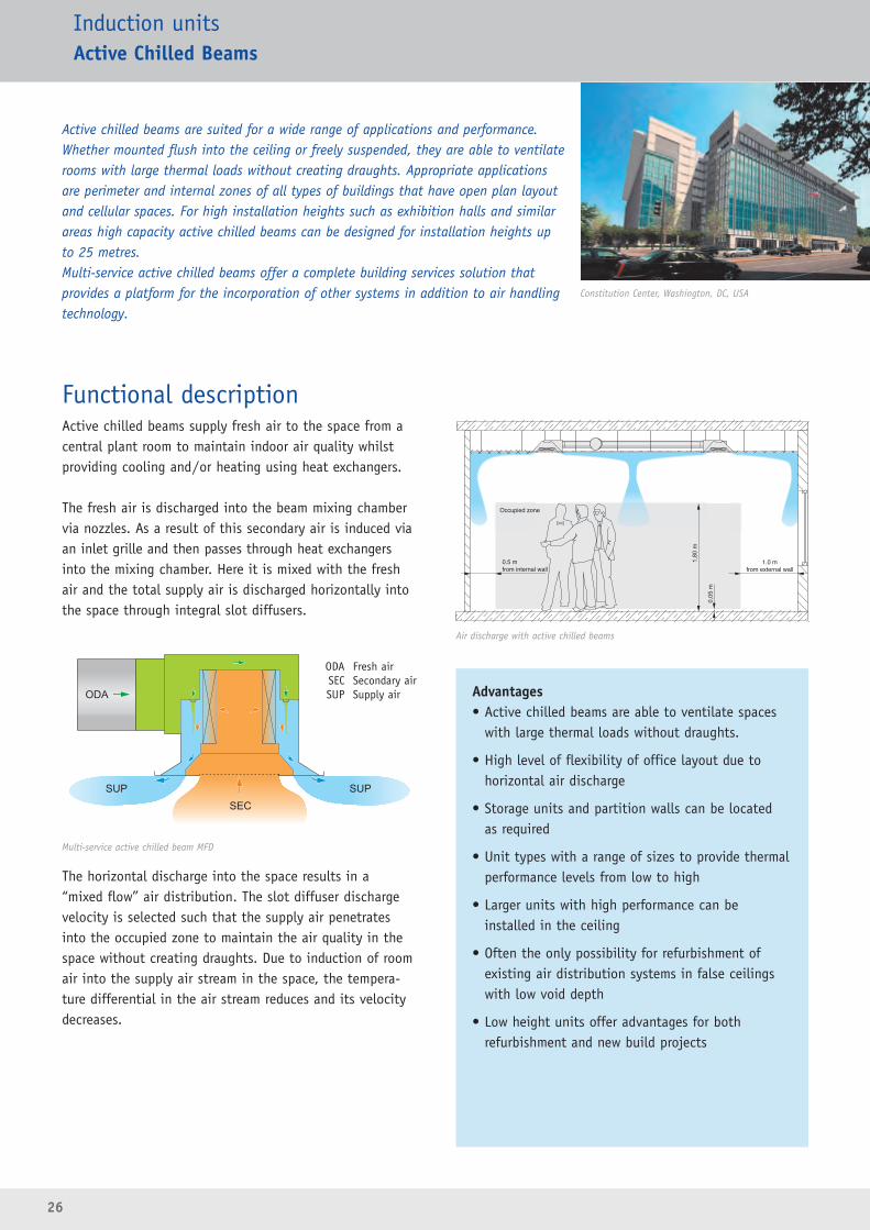
Active chilled beams are suited for a wide range of applications and performance.Whether mounted flush into the ceiling or freely suspended, they are able to ventilaterooms with large thermal loads without creating draughts. Appropriate applicationsare perimeter and internal zones of all types of buildings that have open plan layoutand cellular spaces. For high installation heights such as exhibition halls and similarareas high capacity active chilled beams can be designed for installation heights up to 25 metres.Multi-service active chilled beams offer a complete building services solution that provides a platform for the incorporation of other systems in addition to air handlingtechnology.
Constitution Center, Washington, DC, USA
Occupied zone
0.5 mfrom internal wall
1.0 mfrom external wall
Multi-service active chilled beam MFD
Air discharge with active chilled beams
ODA Fresh airSEC Secondary airSUP Supply air
27
Design informationGeneralActive chilled beams are designed in such a way that theycan be harmoniously integrated into the ceiling’s visualdesign. The dimensions are compatible with conventionalceiling systems. When freely suspended, active chilledbeams can be included as a major design feature of theinterior design.With various configurations of the induction grille there isagain an opportunity to complement the interior design.If the active chilled beams are located on a grid basis this offers flexibility in room sizing to reflect any futurechanges in requirements.
Horizontal air dischargeThe supply air is discharged from the active chilled beamat a relatively high velocity (2 to 4 m/s) which enableseffective room ventilation. In the occupied zone the airvelocity should not exceed 0.2m/s. This is generally thecase when the air stream travels a significant distancebefore entering the occupied zone. For a given roomheight the minimum discharge distance to the nearestwall must be considered. If active chilled beams areinstalled adjacent to each other in a space, again theminimum distance between two beams must be considered
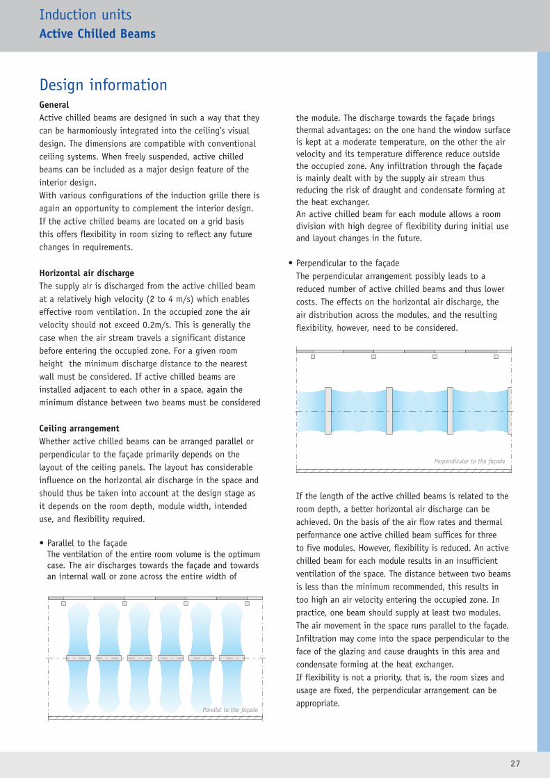
Ceiling arrangementWhether active chilled beams can be arranged parallel orperpendicular to the façade primarily depends on the layout of the ceiling panels. The layout has considerableinfluence on the horizontal air discharge in the space andshould thus be taken into account at the design stage asit depends on the room depth, module width, intendeduse, and flexibility required.
• Parallel to the façadeThe ventilation of the entire room volume is the optimumcase. The air discharges towards the façade and towardsan internal wall or zone across the entire width of
the module. The discharge towards the façade bringsthermal advantages: on the one hand the window surfaceis kept at a moderate temperature, on the other the airvelocity and its temperature difference reduce outsidethe occupied zone. Any infiltration through the façadeis mainly dealt with by the supply air stream thus reducing the risk of draught and condensate forming atthe heat exchanger. An active chilled beam for each module allows a roomdivision with high degree of flexibility during initial useand layout changes in the future.
• Perpendicular to the façadeThe perpendicular arrangement possibly leads to a reduced number of active chilled beams and thus lowercosts. The effects on the horizontal air discharge, theair distribution across the modules, and the resulting flexibility, however, need to be considered.
If the length of the active chilled beams is related to theroom depth, a better horizontal air discharge can beachieved. On the basis of the air flow rates and thermalperformance one active chilled beam suffices for three to five modules. However, flexibility is reduced. An activechilled beam for each module results in an insufficientventilation of the space. The distance between two beamsis less than the minimum recommended, this results intoo high an air velocity entering the occupied zone. Inpractice, one beam should supply at least two modules. The air movement in the space runs parallel to the façade.Infiltration may come into the space perpendicular to theface of the glazing and cause draughts in this area andcondensate forming at the heat exchanger. If flexibility is not a priority, that is, the room sizes andusage are fixed, the perpendicular arrangement can beappropriate.
Induction unitsActive Chilled Beams
Parallel to the façade
Perpendicular to the façade
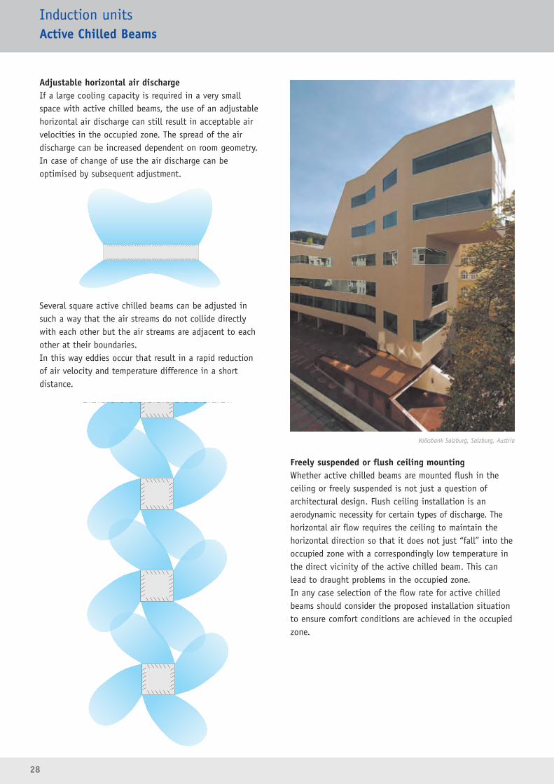
Adjustable horizontal air dischargeIf a large cooling capacity is required in a very smallspace with active chilled beams, the use of an adjustablehorizontal air discharge can still result in acceptable airvelocities in the occupied zone. The spread of the airdischarge can be increased dependent on room geometry. In case of change of use the air discharge can be optimised by subsequent adjustment.
Several square active chilled beams can be adjusted insuch a way that the air streams do not collide directlywith each other but the air streams are adjacent to eachother at their boundaries. In this way eddies occur that result in a rapid reduction of air velocity and temperature difference in a short distance.
Freely suspended or flush ceiling mountingWhether active chilled beams are mounted flush in theceiling or freely suspended is not just a question of architectural design. Flush ceiling installation is an aerodynamic necessity for certain types of discharge. Thehorizontal air flow requires the ceiling to maintain thehorizontal direction so that it does not just “fall” into theoccupied zone with a correspondingly low temperature inthe direct vicinity of the active chilled beam. This canlead to draught problems in the occupied zone.In any case selection of the flow rate for active chilledbeams should consider the proposed installation situationto ensure comfort conditions are achieved in the occupiedzone.
28
Induction unitsActive Chilled Beams
Volksbank Salzburg, Salzburg, Austria

29
Installation into various ceiling systemsActive chilled beams are suitable for all types of ceilingsystems and the dimensions of the units correspond tonormal standards. Due to design details, installation caneasily be with a flush fitting.
• Grid ceilingsActive chilled beams and ceiling tiles are supportedindependently. The edge of the chilled beam lies flushto the ceiling tile.
• Plasterboard ceilingsThe ceiling tile overlaps the straight edge of the activechilled beam.
• T-bar ceilingsThe active chilled beam lies on the T-bar.
Limitations of use• The minimum ceiling or installation height should not
be below 2.60 m.
• In case of ceiling or installation heights up to 3.80 m,the supply air will reach the occupied zone withouttaking special action. Spaces with very high mountingheights are ideally ventilated using Type IDH activechilled beams. Intermediate mounting heights requireproject-specific solutions.
Induction unitsActive Chilled Beams
30
Induction unitsActive Chilled Beams
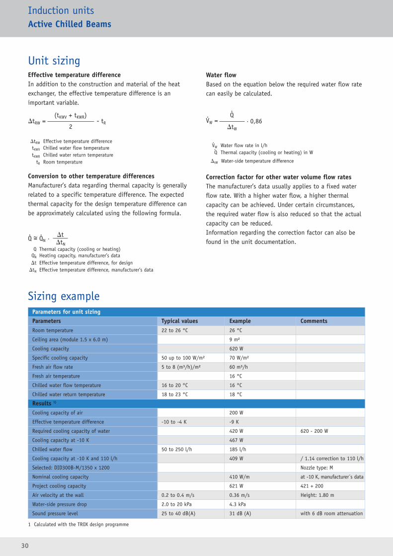
Parameters for unit sizingParameters Typical values Example CommentsRoom temperature 22 to 26 °C 26 °C
Ceiling area (module 1.5 x 6.0 m) 9 m²
Cooling capacity 620 W
Specific cooling capacity 50 up to 100 W/m² 70 W/m²
Fresh air flow rate 5 to 8 (m³/h)/m² 60 m³/h
Fresh air temperature 16 °C
Chilled water flow temperature 16 to 20 °C 16 °C
Chilled water return temperature 18 to 23 °C 18 °C
Results 1)
Cooling capacity of air 200 W
Effective temperature difference -10 to -4 K -9 K
Required cooling capacity of water 420 W 620 - 200 W
Cooling capacity at -10 K 467 W
Chilled water flow 50 to 250 l/h 185 l/h
Cooling capacity at -10 K and 110 l/h 409 W / 1.14 correction to 110 l/h
Selected: DID300B-M/1350 x 1200 Nozzle type: M
Nominal cooling capacity 410 W/m at -10 K, manufacturer´s data
Project cooling capacity 621 W 421 + 200
Air velocity at the wall 0.2 to 0.4 m/s 0.36 m/s Height: 1.80 m
Water-side pressure drop 2.0 to 20 kPa 4.3 kPa
Sound pressure level 25 to 40 dB(A) 31 dB (A) with 6 dB room attenuation
Sizing example
Unit sizingEffective temperature differenceIn addition to the construction and material of the heatexchanger, the effective temperature difference is animportant variable.
�tRW Effective temperature differencetKWV Chilled water flow temperaturetKWR Chilled water return temperature
tR Room temperature
Conversion to other temperature differencesManufacturer’s data regarding thermal capacity is generallyrelated to a specific temperature difference. The expectedthermal capacity for the design temperature difference canbe approximately calculated using the following formula.
Q Thermal capacity (cooling or heating)QN Heating capacity, manufacturer’s data�t Effective temperature difference, for design
�tN Effective temperature difference, manufacturer’s data
Water flowBased on the equation below the required water flow ratecan easily be calculated.
VW Water flow rate in l/hQ Thermal capacity (cooling or heating) in W
�tW Water-side temperature difference
Correction factor for other water volume flow ratesThe manufacturer’s data usually applies to a fixed waterflow rate. With a higher water flow, a higher thermalcapacity can be achieved. Under certain circumstances,the required water flow is also reduced so that the actualcapacity can be reduced.Information regarding the correction factor can also befound in the unit documentation.
..
..
1 Calculated with the TROX design programme
�tRW =(tKWV + tKWR)
- tR2
Q = QN · �tN
�t. .~
VW =Q
· 0,86�tW
..

31
Induction unitsActive Chilled Beams
DID312 DID300B DID604 DID632 AKV DID-R DID-E IDH
Installation details
Freely suspended • •
Grid ceilings 300 mm 300 mm 600 mm 600 mm 300 mm
T-bar ceilings
Continuous falseceilings
• • • • • • •
Heat exchanger
Coil configuration 2 or 4 2 or 4 2 or 4 2 or 4 2 2 or 4 2 or 4 2
Condensate drip tray • • • •
Performance data
[l/s] 5 – 70 3 – 45 5 – 50 5 – 70 12 – 80 12 – 25 10 – 78 278/555Fresh airflow rate
[m3/h] 18 – 252 10 – 160 18 – 180 10 – 252 43 – 288 43 – 90 36 – 281 1000/2000
cooling capacity [W]1800 1600 1600 2500 1600 500 1000 27000
heating capacity [W]1250 1250 1700 3000 1530 1200 500 10000
Maximum
Maximum

32
Induction unitsActive Chilled Beams
Nominal width 300 mm
Nominal width size 600 mm
Type DID300B
Type DID604
Type DID312
� Four options of induced air grille design� Heat exchanger vertically mounted with condensate drip
tray for low chilled water temperatures� Side entry spigot for fresh air� Supply-extract-air combination available
L: 900 – 3000 mm · H: 210 and 241 mm5 – 70 l/s · 18 – 252 m³/h fresh airCooling capacity up to 1800 WHeating capacity up to 1250 W
� Side or top entry spigot for fresh air � Supply-extract-air combination available
L: 900 – 3000 mm · H: 210 mm3 – 45 l/s · 10 – 160 m³/h fresh airCooling capacity up to 1600 WHeating capacity up to 1250 W
� Four-way air discharge� Adjustable control blades to control the air discharge
direction � Side entry spigot for fresh air� Heat exchanger vertically mounted with condensate drip
tray for low chilled water temperatures
L: 600 and 1200 mm · H: 225 mm5 – 50 l/s · 18 – 180 m³/h fresh airCooling capacity up to 1600 WHeating capacity up to 1700 W
� Large cooling capacity� Four options of induced air grille design� Adjustable control blades to control the air discharge
direction � Adjustable induction nozzle configuration� Side entry spigot for fresh air� Supply-extract-air combination available
L: 900 – 3000 mm · H: 210 mm5 – 70 l/s · 18 – 252 m³/h fresh airCooling capacity up to 2500 WHeating capacity up to 3000 W
Type DID632
33
Induction unitsActive Chilled Beams
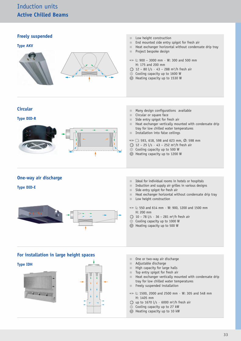
Freely suspended
Type AKV
Circular
Type DID-R
One-way air discharge
Type DID-E
For installation in large height spaces
Type IDH
� Low height construction� End mounted side entry spigot for fresh air� Heat exchanger horizontal without condensate drip tray� Project bespoke design
L: 900 – 3000 mm · W: 300 and 500 mmH: 175 and 200 mm12 – 80 l/s · 43 – 288 m³/h fresh airCooling capacity up to 1600 WHeating capacity up to 1530 W
� Many design configurations available� Circular or square face� Side entry spigot for fresh air� Heat exchanger vertically mounted with condensate drip
tray for low chilled water temperatures� Installation into false ceilings
�: 593, 618, 598 and 623 mm, Ø: 598 mm12 – 25 l/s · 43 – 252 m³/h fresh airCooling capacity up to 500 WHeating capacity up to 1200 W
� Ideal for individual rooms in hotels or hospitals� Induction and supply air grilles in various designs� Side entry spigot for fresh air� Heat exchanger horizontal without condensate drip tray� Low height construction
L: 550 and 614 mm · W: 900, 1200 and 1500 mmH: 200 mm10 – 78 l/s · 36 – 281 m³/h fresh airCooling capacity up to 1000 WHeating capacity up to 500 W
� One or two-way air discharge� Adjustable discharge� High capacity for large halls� Top entry spigot for fresh air� Heat exchanger vertically mounted with condensate drip
tray for low chilled water temperatures� Freely suspended installation
L: 1500, 2000 and 2500 mm · W: 305 and 548 mmH: 1405 mm up to 1670 l/s · 6000 m³/h fresh airCooling capacity up to 27 kWHeating capacity up to 10 kW
34
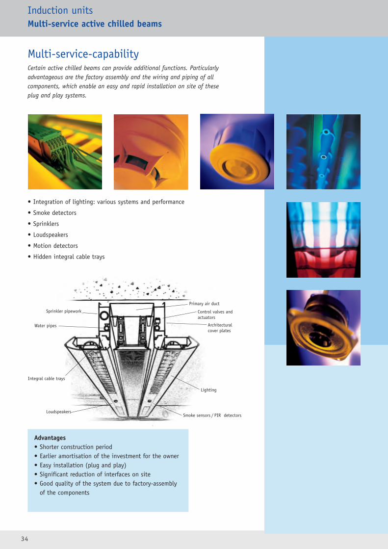
• Integration of lighting: various systems and performance
• Smoke detectors
• Sprinklers
• Loudspeakers
• Motion detectors
• Hidden integral cable trays
Multi-service-capabilityCertain active chilled beams can provide additional functions. Particularly advantageous are the factory assembly and the wiring and piping of all components, which enable an easy and rapid installation on site of these plug and play systems.
Advantages• Shorter construction period• Earlier amortisation of the investment for the owner• Easy installation (plug and play)• Significant reduction of interfaces on site• Good quality of the system due to factory-assembly
of the components
Primary air duct
Control valves andactuators
Architectural cover plates
Lighting
Smoke sensors / PIR detectors
Sprinkler pipework
Water pipes
Integral cable trays
Loudspeakers
Induction unitsMulti-service active chilled beams
35
Induction unitsMulti-service active chilled beams
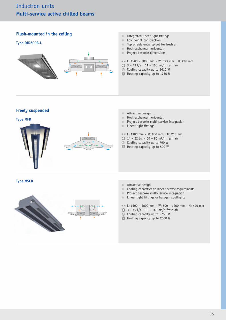
Type MSCB
� Integrated linear light fittings� Low height construction� Top or side entry spigot for fresh air� Heat exchanger horizontal� Project bespoke dimensions
L: 1500 – 3000 mm · W: 593 mm · H: 210 mm3 – 43 l/s · 11 – 155 m³/h fresh airCooling capacity up to 1610 WHeating capacity up to 1730 W
� Attractive design� Heat exchanger horizontal � Project bespoke multi-service integration� Linear light fittings
L: 1980 mm · W: 800 mm · H: 213 mm14 – 22 l/s · 50 – 80 m³/h fresh airCooling capacity up to 790 WHeating capacity up to 500 W
� Attractive design� Cooling capacities to meet specific requirements� Project bespoke multi-service integration� Linear light fittings or halogen spotlights
L: 1500 – 5000 mm · W: 600 – 1200 mm · H: 440 mm3 – 45 l/s · 10 – 160 m³/h fresh airCooling capacity up to 2750 WHeating capacity up to 2000 W
Flush-mounted in the ceiling
Type DID600B-L
Freely suspended
Type MFD
36
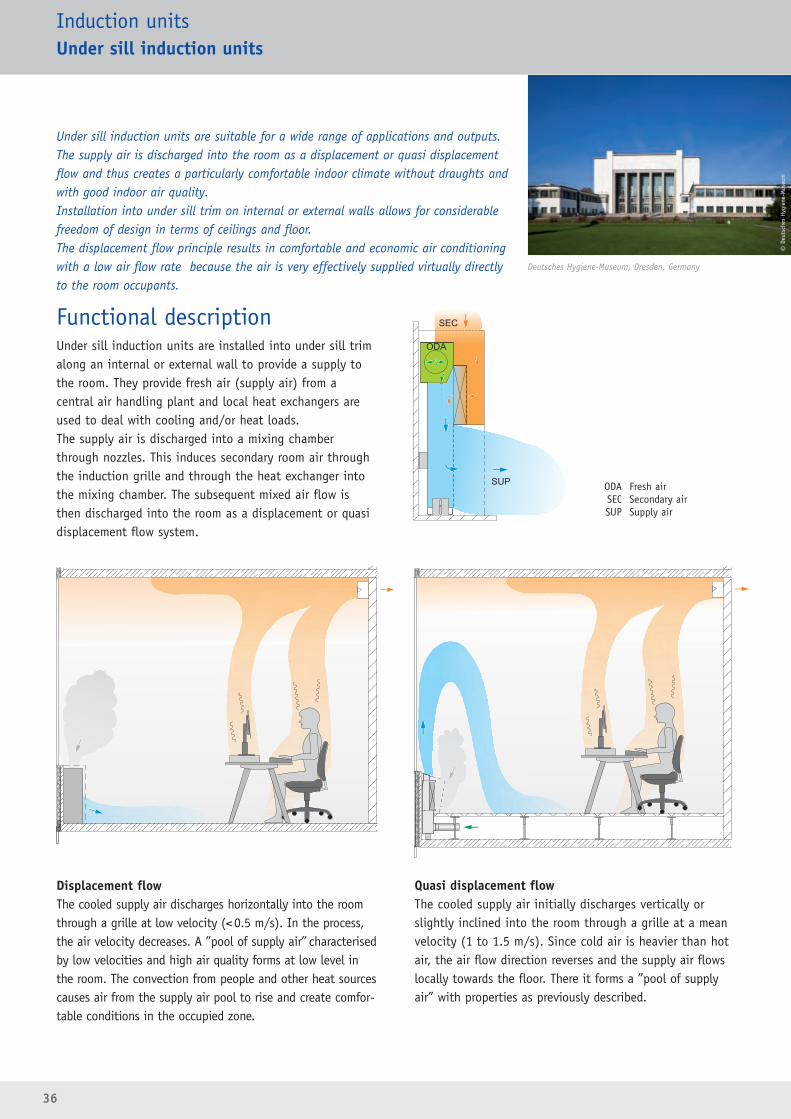
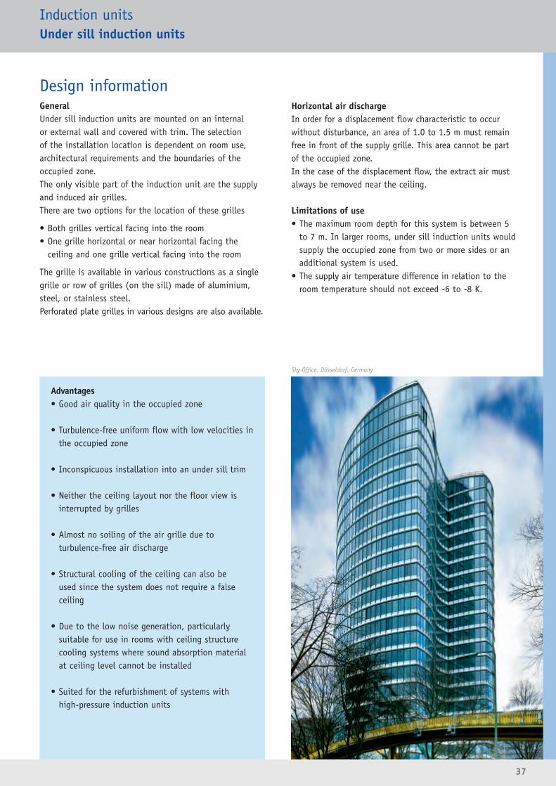
Under sill induction units are suitable for a wide range of applications and outputs.The supply air is discharged into the room as a displacement or quasi displacementflow and thus creates a particularly comfortable indoor climate without draughts andwith good indoor air quality.Installation into under sill trim on internal or external walls allows for considerable freedom of design in terms of ceilings and floor.The displacement flow principle results in comfortable and economic air conditioningwith a low air flow rate because the air is very effectively supplied virtually directlyto the room occupants.
Induction unitsUnder sill induction units
Functional descriptionUnder sill induction units are installed into under sill trimalong an internal or external wall to provide a supply tothe room. They provide fresh air (supply air) from a central air handling plant and local heat exchangers areused to deal with cooling and/or heat loads. The supply air is discharged into a mixing chamberthrough nozzles. This induces secondary room air throughthe induction grille and through the heat exchanger intothe mixing chamber. The subsequent mixed air flow isthen discharged into the room as a displacement or quasidisplacement flow system.
Displacement flowThe cooled supply air discharges horizontally into the roomthrough a grille at low velocity (<0.5 m/s). In the process,the air velocity decreases. A ”pool of supply air” characterisedby low velocities and high air quality forms at low level inthe room. The convection from people and other heat sourcescauses air from the supply air pool to rise and create comfor-table conditions in the occupied zone.
Quasi displacement flowThe cooled supply air initially discharges vertically orslightly inclined into the room through a grille at a meanvelocity (1 to 1.5 m/s). Since cold air is heavier than hotair, the air flow direction reverses and the supply air flowslocally towards the floor. There it forms a ”pool of supplyair” with properties as previously described.
Deutsches Hygiene-Museum, Dresden, Germany
ODA Fresh airSEC Secondary airSUP Supply air
©De
utsc
hes
Hyg
iene
-Mus
eum
37
Advantages• Good air quality in the occupied zone
• Turbulence-free uniform flow with low velocities inthe occupied zone
• Inconspicuous installation into an under sill trim
• Neither the ceiling layout nor the floor view isinterrupted by grilles
• Almost no soiling of the air grille due to turbulence-free air discharge
• Structural cooling of the ceiling can also be used since the system does not require a false ceiling
• Due to the low noise generation, particularly suitable for use in rooms with ceiling structurecooling systems where sound absorption materialat ceiling level cannot be installed
• Suited for the refurbishment of systems with high-pressure induction units
Design informationGeneralUnder sill induction units are mounted on an internal or external wall and covered with trim. The selection of the installation location is dependent on room use, architectural requirements and the boundaries of the occupied zone.The only visible part of the induction unit are the supplyand induced air grilles.There are two options for the location of these grilles
• Both grilles vertical facing into the room• One grille horizontal or near horizontal facing the
ceiling and one grille vertical facing into the room
The grille is available in various constructions as a singlegrille or row of grilles (on the sill) made of aluminium,steel, or stainless steel. Perforated plate grilles in various designs are also available.
Horizontal air dischargeIn order for a displacement flow characteristic to occurwithout disturbance, an area of 1.0 to 1.5 m must remainfree in front of the supply grille. This area cannot be partof the occupied zone.In the case of the displacement flow, the extract air mustalways be removed near the ceiling.
Limitations of use• The maximum room depth for this system is between 5
to 7 m. In larger rooms, under sill induction units wouldsupply the occupied zone from two or more sides or anadditional system is used.
• The supply air temperature difference in relation to theroom temperature should not exceed -6 to -8 K.
Induction unitsUnder sill induction units
Sky-Office. Düsseldorf, Germany
38
Induction unitsUnder sill induction units
Unit sizingEffective temperature differenceIn addition to the construction and material of the heatexchanger, the effective temperature difference is an important variable.
ΔtRW Effective temperature differencetKWV Chilled water flow temperaturetKWR Chilled water return temperature
tR Room temperature
Conversion to other temperature differencesManufacturer’s data regarding thermal capacity is generallyrelated to a specific temperature difference. The followingformula is used for conversion to the project design temperature difference.
Q Thermal capacity (cooling or heating)QN Heating capacity, manufacturer’s dataΔt Effective temperature difference, for designΔtN Effective temperature difference, manufacturer’s data
Water flowBased on the equation below the required water flow ratecan be easily calculated.
VW Water flow rate in l/h
Q Thermal capacity (cooling or heating) in WΔtW Water-side temperature difference
Correction factor for other water volume flow ratesThe manufacturer’s data usually applies to a fixed waterflow rate. With a higher water flow, a higher thermalcapacity can be achieved. Under certain circumstances,the required water flow is also reduced so that the actualcapacity can be reduced.Information regarding the correction factor can also befound in the unit documentation.
ΔtRW =(tKWV + tKWR)
- tR2
VW = · 0.86Q
ΔtW
..
..
Q = QN · ΔtN
ΔtDt. .~
..
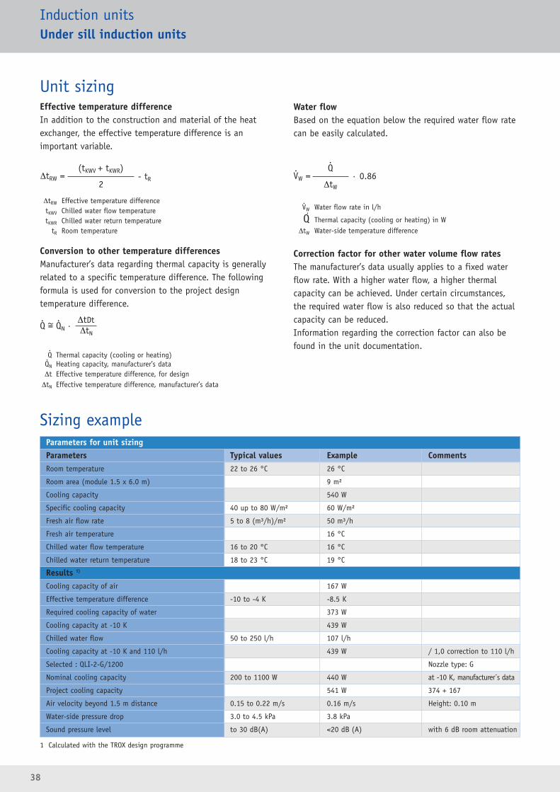
Parameters for unit sizingParameters Typical values Example CommentsRoom temperature 22 to 26 °C 26 °C
Room area (module 1.5 x 6.0 m) 9 m²
Cooling capacity 540 W
Specific cooling capacity 40 up to 80 W/m² 60 W/m²
Fresh air flow rate 5 to 8 (m³/h)/m² 50 m³/h
Fresh air temperature 16 °C
Chilled water flow temperature 16 to 20 °C 16 °C
Chilled water return temperature 18 to 23 °C 19 °C
Results 1)
Cooling capacity of air 167 W
Effective temperature difference -10 to -4 K -8.5 K
Required cooling capacity of water 373 W
Cooling capacity at -10 K 439 W
Chilled water flow 50 to 250 l/h 107 l/h
Cooling capacity at -10 K and 110 l/h 439 W / 1,0 correction to 110 l/h
Selected : QLI-2-G/1200 Nozzle type: G
Nominal cooling capacity 200 to 1100 W 440 W at -10 K, manufacturer´s data
Project cooling capacity 541 W 374 + 167
Air velocity beyond 1.5 m distance 0.15 to 0.22 m/s 0.16 m/s Height: 0.10 m
Water-side pressure drop 3.0 to 4.5 kPa 3.8 kPa
Sound pressure level to 30 dB(A) <20 dB (A) with 6 dB room attenuation
Sizing example
1 Calculated with the TROX design programme
39
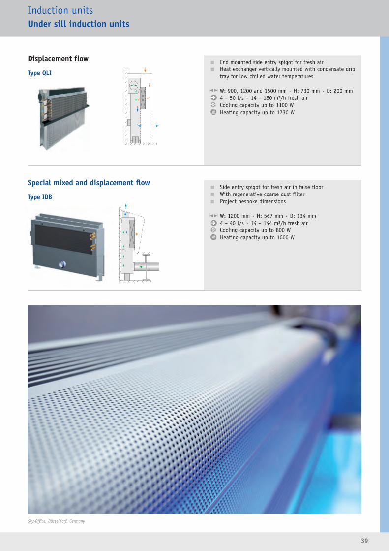
Displacement flow
Special mixed and displacement flow
Type QLI
Type IDB
Induction unitsUnder sill induction units
� End mounted side entry spigot for fresh air� Heat exchanger vertically mounted with condensate drip
tray for low chilled water temperatures
W: 900, 1200 and 1500 mm · H: 730 mm · D: 200 mm4 – 50 l/s · 14 – 180 m³/h fresh airCooling capacity up to 1100 WHeating capacity up to 1730 W
� Side entry spigot for fresh air in false floor� With regenerative coarse dust filter� Project bespoke dimensions
W: 1200 mm · H: 567 mm · D: 134 mm4 – 40 l/s · 14 – 144 m³/h fresh airCooling capacity up to 800 WHeating capacity up to 1000 W
Sky-Office, Düsseldorf, Germany
40
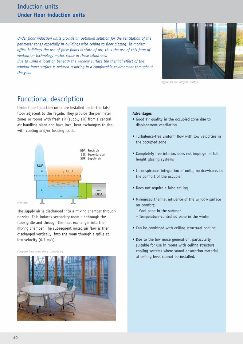
Functional descriptionUnder floor induction units are installed under the falsefloor adjacent to the façade. They provide the perimeterzones or rooms with fresh air (supply air) from a centralair handling plant and have local heat exchangers to dealwith cooling and/or heating loads.
The supply air is discharged into a mixing chamber throughnozzles. This induces secondary room air through the floor grille and through the heat exchanger into themixing chamber. The subsequent mixed air flow is thendischarged vertically into the room through a grille atlow velocity (0.7 m/s).
Induction unitsUnder floor induction units
Under floor induction units provide an optimum solution for the ventilation of theperimeter zones especially in buildings with ceiling to floor glazing. In modernoffice buildings the use of false floors is state of art, thus the use of this form ofventilation technology makes sense in these situations.Due to using a location beneath the window surface the thermal effect of thewindow inner surface is reduced resulting in a comfortable environment throughoutthe year.
Advantages• Good air quality in the occupied zone due to
displacement ventilation
• Turbulence-free uniform flow with low velocities inthe occupied zone
• Completely free interior, does not impinge on fullheight glazing systems
• Inconspicuous integration of units, no drawbacks tothe comfort of the occupier
• Does not require a false ceiling
• Minimised thermal influence of the window surfaceon comfort:– Cool pane in the summer– Temperature-controlled pane in the winter
• Can be combined with ceiling structural cooling
• Due to the low noise generation, particularly suitable for use in rooms with ceiling structure cooling systems where sound absorption material at ceiling level cannot be installed.
Office am See, Bregenz, Austria
European Investment Bank, Luxembourg
ODA Fresh airSEC Secondary airSUP Supply air
View BID

41
Cooling operationThe horizontal air discharge into the room takes placesimilar to displacement ventilation. The cooled supply airinitially discharges upwards. Since cold air is heavier thanwarm air, the air flow direction reverses and the supply airflows locally towards the floor. In the process, the airvelocity decreases. A ”pool of supply air” characterised bylow air velocities and good air quality forms at low levelwithin the room. The convection from people and otherheat sources causes air from ”the supply air pool” to riseand create comfortable conditions in the occupied zone. A part of the air discharge from the grille is already heated by the window surface and conducted further upthe window. In the interest of occupant comfort, thiseffect is desirable since the surface temperature of thepane thus remains low.
Heating operationThe supply air, which is heated or at room temperature,discharges vertically upwards. With an increasing, positivetemperature difference between the supply air and localair, the air flow can no longer return to the floor and as aresult a mixed flow air distribution is set up in the space.The warm air stream up the window surface has a positiveinfluence on the perception of the occupants because thesurface temperature of the window surface increases. The uncomfortable feeling that arises near cold windowsurfaces (cold radiation) fails to materialise.
Heating operation without supply airIn heating operation without supply air (operating mode:stand-by), the under floor induction unit operates as astatic heater. The air in the heat exchanger is heated andrises due to convection. The air adjacent to the windowsurface can only fall down to the heat exchanger. Thus the heat loss from the window surface is directly com -pensated for.
Induction unitsUnder floor induction units
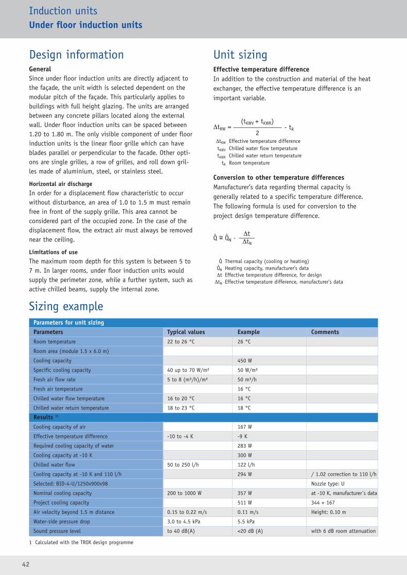
42
Design informationGeneralSince under floor induction units are directly adjacent tothe façade, the unit width is selected dependent on themodular pitch of the façade. This particularly applies tobuildings with full height glazing. The units are arrangedbetween any concrete pillars located along the externalwall. Under floor induction units can be spaced between1.20 to 1.80 m. The only visible component of under floorinduction units is the linear floor grille which can haveblades parallel or perpendicular to the facade. Other opti-ons are single grilles, a row of grilles, and roll down gril-les made of aluminium, steel, or stainless steel.
Horizontal air dischargeIn order for a displacement flow characteristic to occurwithout disturbance, an area of 1.0 to 1.5 m must remainfree in front of the supply grille. This area cannot be considered part of the occupied zone. In the case of thedisplacement flow, the extract air must always be removednear the ceiling.
Limitations of useThe maximum room depth for this system is between 5 to7 m. In larger rooms, under floor induction units wouldsupply the perimeter zone, while a further system, such asactive chilled beams, supply the internal zone.
Unit sizing Effective temperature differenceIn addition to the construction and material of the heatexchanger, the effective temperature difference is an important variable.
ΔtRW Effective temperature differencetKWV Chilled water flow temperaturetKWR Chilled water return temperature
tR Room temperature
Conversion to other temperature differencesManufacturer’s data regarding thermal capacity is generally related to a specific temperature difference. The following formula is used for conversion to the project design temperature difference.
Q Thermal capacity (cooling or heating)QN Heating capacity, manufacturer’s dataΔt Effective temperature difference, for designΔtN Effective temperature difference, manufacturer’s data
Induction unitsUnder floor induction units
ΔtRW =(tKWV + tKWR)
- tR2
Q = QN · ΔtN
Δt. .~
..
Parameters for unit sizingParameters Typical values Example CommentsRoom temperature 22 to 26 °C 26 °C
Room area (module 1.5 x 6.0 m)
Cooling capacity 450 W
Specific cooling capacity 40 up to 70 W/m² 50 W/m²
Fresh air flow rate 5 to 8 (m³/h)/m² 50 m³/h
Fresh air temperature 16 °C
Chilled water flow temperature 16 to 20 °C 16 °C
Chilled water return temperature 18 to 23 °C 18 °C
Results 1)
Cooling capacity of air 167 W
Effective temperature difference -10 to -4 K -9 K
Required cooling capacity of water 283 W
Cooling capacity at -10 K 300 W
Chilled water flow 50 to 250 l/h 122 l/h
Cooling capacity at -10 K and 110 l/h 294 W / 1.02 correction to 110 l/h
Selected: BID-4-U/1250x900x98 Nozzle type: U
Nominal cooling capacity 200 to 1000 W 357 W at -10 K, manufacturer´s data
Project cooling capacity 511 W 344 + 167
Air velocity beyond 1.5 m distance 0.15 to 0.22 m/s 0.11 m/s Height: 0.10 m
Water-side pressure drop 3.0 to 4.5 kPa 5.5 kPa
Sound pressure level to 40 dB(A) <20 dB (A) with 6 dB room attenuation
Sizing example
1 Calculated with the TROX design programme

43
Induction unitsUnder floor induction units
Type BID� Rectangular floor grille in various configurations and
materials� Low construction height� Project bespoke dimensions
W: 1100 – 1849 mm · H: 191 mm · D: 404 mm4 – 40 l/s · 14 – 144 m³/h fresh airCooling capacity up to 1030 WHeating capacity up to 1225 W
European Investment Bank, Luxembourg
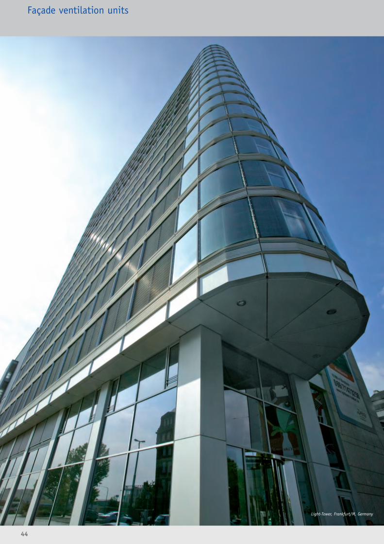
44
Façade ventilation units
Light-Tower, Frankfurt/M, Germany

45
Advantages• Good occupant acceptance and satisfaction:– Individual control– Opening windows can be used
• Good level of energy efficiency:– System shuts down when not in use or when
windows are opened– Heat recovery available
• Low energy requirement as air is supplied to the roomat low speed and using the shortest possible route
• As a result very good fan efficiencies are achieved, low specific fan powers (SFP)
• Very efficient use of space as central air handling plantand ductwork distribution systems are not required
• Often the only practical method to refurbish a buildingwith a mechanical ventilation/air conditioning systemat an acceptable cost
• Simple recording of services costs and simplified billingfor multi rental spaces
Functional descriptionFaçade ventilation units can offer various decentralised airhandling functions. They are arranged in or on externalwalls or façades. The units allow noise controlled airhandling from the inside to the outside or vice versa usingthe shortest possible path. A duct distribution system isnot required.Façade ventilation units are usually project-specific solutions based on sophisticated, proven functional units. For the selection and understanding of these units, thefollowing criteria are very important: the required conceptfor the decentralised system, the range of functions required and the installation location. Up to now, basedon a combination of the above criteria, numerous projectshave been fitted out with façade ventilation units. For thefuture even more options will be available.
Decentralised ventilation systemsRooms can be ventilated solely using decentralised façadeventilation units, or the units can be used to supplementcentral plant systems.FunctionsThe range of functions available in façade ventilationunits can be from static inflow/outflow units to minipowered air handling units. Innovative technology is also available with units using phase change materials.
In the following, the unit options are described in detail,including the functional modular inserts and componentsavailable.
Installation locationThe installation locations are primarily divided into under sill
and under floor. Under sill units can be installed below the sill
(below the window), in front of the sill, or also on top of or to
the side of the window. Under floor units are installed into the
false floor void adjacent to the
façade. They are an ideal solution
for projects with full height
glazing. Façade ventilation units
can also be integrated into the
actual façade. The off site fabri -
cation of the façade element plus
the ventilation unit offers
improved site logistics and hence
very good quality and reduction
in costs.
Façade ventilation units
Decentralising ventilation systems and mounting them into or onto the façade bringsadvantages in terms of design, comfort, and economics to many projects. The spacerequirement for plant rooms and ducts is no longer required or reduced drastically. Thishas considerable influence on the slab to slab room height and thus on the entire building investment.For new construction projects, innovative project-specific ventilation systems that offergreat flexibility and energy-efficiency are available using façade ventilation units.Since façade ventilation units require no central air handling plant, they are often theonly and ideal solution for the refurbishment of an existing building with ventilationand air conditioning systems. Air flow measurement

46
Decentralised ventilation systemsDecentralised supply air – Centralised extract airFaçade ventilation units maintain the air quality in roomsby supplying fresh air to the room. In the simplest case,static inflow units let as much air flow into the room aswill be removed by the powered extract air system. Supplyair units that have a fan allow controlled ventilation witha regulated or limited fresh air flow rate. The fresh air canalso be tempered and filtered.The extract air is removed at floor level by room or groupsof room using a central extract air system.Application example: refurbishment for the improvementof the indoor air quality using the existing extract air sys-tem.
Decentralised supply air and extract airThe entire ventilation is decentralised. A very good indoorair quality is achieved using façade ventilation units sincethey supply conditioned fresh air directly to the room. Airtreatment and air handling are combined in a single unit.Air treatment is performed to meet the project-specificrequirements and conditions.Even the room extract air is exhausted to the outside usingthe façade ventilation unit. For this purpose, combinedsupply and extract air units are available.Application example: New construction or refurbishmentwith decentralised ventilation technology.
Secondary airRooms and zones with high thermal loads are only sup-plied with the fresh air flow rate required to maintain theair quality. Any heating or cooling capacities required be -yond this can be provided with secondary/recirculation airunits. They can effectively supplement both decentralisedand centralised ventilation systems.Application example: New construction, refurbishment, orretrofit.
Large zonesFor the ventilation of large zones, a combination of façadeventilation units with, for example, active chilled beams,is a good solution.
Façade ventilation units
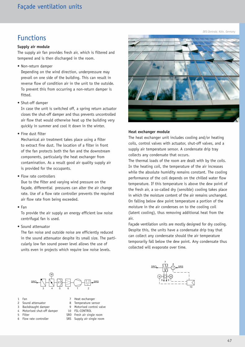
47
FunctionsSupply air moduleThe supply air fan provides fresh air, which is filtered andtempered and is then discharged in the room.
• Non-return damperDepending on the wind direction, underpressure mayprevail on one side of the building. This can result inreverse flow of condition air in the unit to the outside.To prevent this from occurring a non-return damper isfitted.
• Shut-off damperIn case the unit is switched off, a spring return actuatorcloses the shut-off damper and thus prevents uncontrolledair flow that would otherwise heat up the building veryquickly in summer and cool it down in the winter.
• Fine dust filterMechanical air treatment takes place using a filter to extract fine dust. The location of a filter in front of the fan protects both the fan and the downstream components, particularly the heat exchanger from contamination. As a result good air quality supply air is provided for the occupants.
• Flow rate controllersDue to the filter and varying wind pressure on thefaçade, differential pressures can alter the air changerate. Use of a flow rate controller prevents the requiredair flow rate from being exceeded.
• FanTo provide the air supply an energy efficient low noisecentrifugal fan is used.
• Sound attenuatorThe fan noise and outside noise are efficiently reducedin the sound attenuator despite its small size. The parti-cularly low fan sound power level allows the use ofunits even in projects which require low noise levels.
Heat exchanger moduleThe heat exchanger unit includes cooling and/or heatingcoils, control valves with actuator, shut-off valves, and asupply air temperature sensor. A condensate drip tray collects any condensate that occurs.The thermal loads of the room are dealt with by the coils.In the heating coil, the temperature of the air increaseswhile the absolute humidity remains constant. The coolingperformance of the coil depends on the chilled water flowtemperature. If this temperature is above the dew point ofthe fresh air, a so-called dry (sensible) cooling takes placein which the moisture content of the air remains unchanged.On falling below dew point temperature a portion of themoisture in the air condenses on to the cooling coil(latent cooling), thus removing additional heat from theair.Façade ventilation units are mostly designed for dry cooling.Despite this, the units have a condensate drip tray thatcan collect any condensate should the air temperaturetemporarily fall below the dew point. Any condensate thuscollected will evaporate over time.
1 Fan2 Sound attenuator3 Backdraught damper4 Motorised shut-off damper 5 Filter6 Flow rate controller
7 Heat exchanger8 Temperature sensor9 Motorised control valve
10 FSL-CONTROLSRO Fresh air single roomSRS Supply air single room
DEG-Zentrale, Köln, Germany
Façade ventilation units
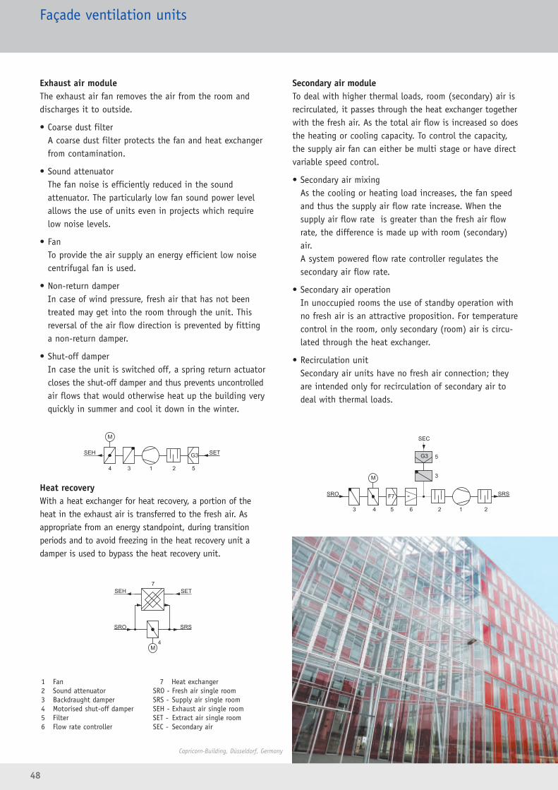
Exhaust air moduleThe exhaust air fan removes the air from the room anddischarges it to outside.
• Coarse dust filterA coarse dust filter protects the fan and heat exchangerfrom contamination.
• Sound attenuatorThe fan noise is efficiently reduced in the sound attenuator. The particularly low fan sound power levelallows the use of units even in projects which requirelow noise levels.
• FanTo provide the air supply an energy efficient low noisecentrifugal fan is used.
• Non-return damperIn case of wind pressure, fresh air that has not beentreated may get into the room through the unit. Thisreversal of the air flow direction is prevented by fittinga non-return damper.
• Shut-off damperIn case the unit is switched off, a spring return actuatorcloses the shut-off damper and thus prevents uncontrolledair flows that would otherwise heat up the building veryquickly in summer and cool it down in the winter.
Heat recoveryWith a heat exchanger for heat recovery, a portion of theheat in the exhaust air is transferred to the fresh air. Asappropriate from an energy standpoint, during transitionperiods and to avoid freezing in the heat recovery unit adamper is used to bypass the heat recovery unit.
Secondary air module To deal with higher thermal loads, room (secondary) air isrecirculated, it passes through the heat exchanger togetherwith the fresh air. As the total air flow is increased so doesthe heating or cooling capacity. To control the capacity,the supply air fan can either be multi stage or have directvariable speed control.
• Secondary air mixingAs the cooling or heating load increases, the fan speedand thus the supply air flow rate increase. When thesupply air flow rate is greater than the fresh air flowrate, the difference is made up with room (secondary)air. A system powered flow rate controller regulates thesecondary air flow rate.
• Secondary air operationIn unoccupied rooms the use of standby operation withno fresh air is an attractive proposition. For temperaturecontrol in the room, only secondary (room) air is circu-lated through the heat exchanger.
• Recirculation unitSecondary air units have no fresh air connection; theyare intended only for recirculation of secondary air todeal with thermal loads.
48
1 Fan2 Sound attenuator3 Backdraught damper4 Motorised shut-off damper5 Filter6 Flow rate controller
7 Heat exchangerSRO - Fresh air single roomSRS - Supply air single roomSEH - Exhaust air single roomSET - Extract air single roomSEC - Secondary air
Façade ventilation units
Capricorn-Building, Düsseldorf, Germany
4
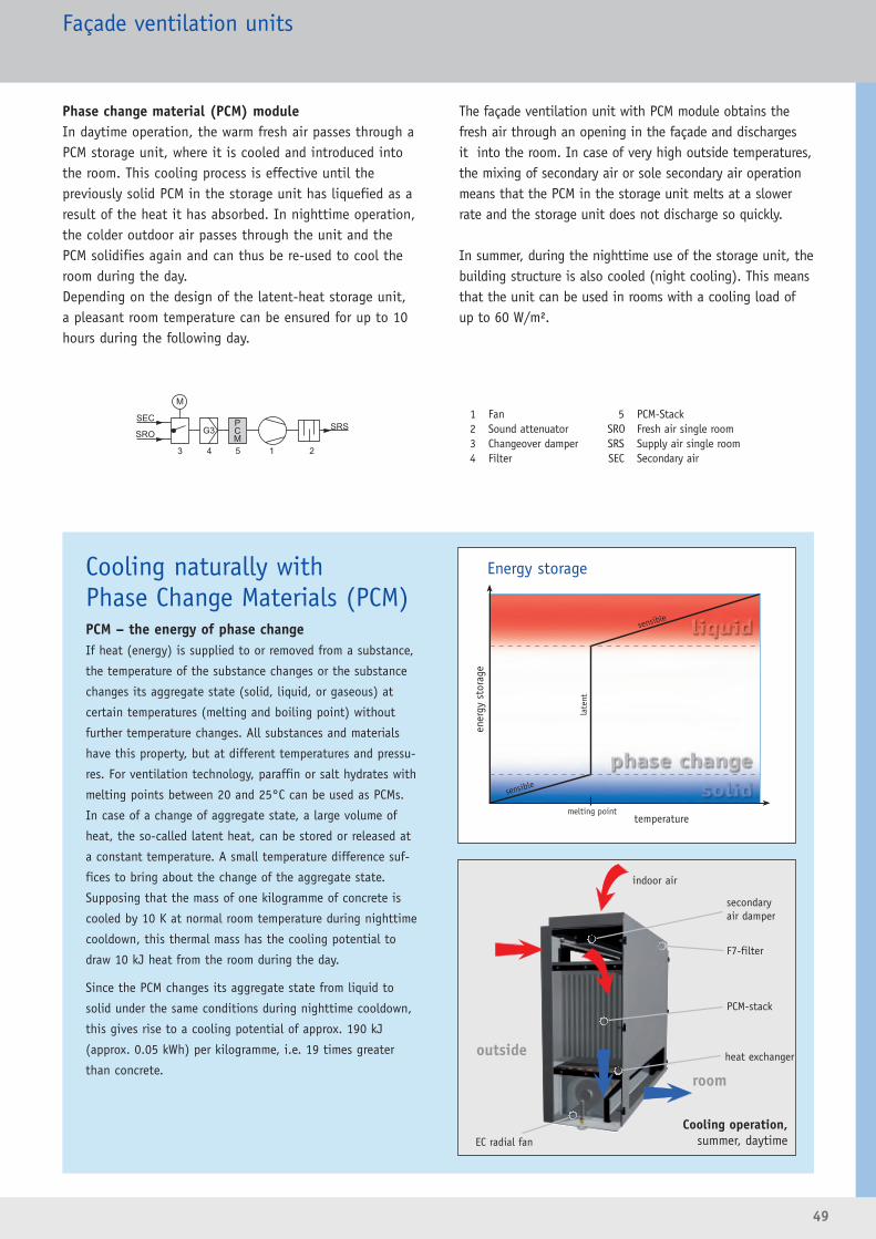
49
Façade ventilation units
sensible
late
nt
sensible
temperature
ener
gy s
tora
ge
melting point
Energy storage
Phase change material (PCM) moduleIn daytime operation, the warm fresh air passes through aPCM storage unit, where it is cooled and introduced intothe room. This cooling process is effective until the previously solid PCM in the storage unit has liquefied as aresult of the heat it has absorbed. In nighttime operation,the colder outdoor air passes through the unit and thePCM solidifies again and can thus be re-used to cool theroom during the day.Depending on the design of the latent-heat storage unit,a pleasant room temperature can be ensured for up to 10hours during the following day.
The façade ventilation unit with PCM module obtains thefresh air through an opening in the façade and discharges it into the room. In case of very high outside temperatures,the mixing of secondary air or sole secondary air operationmeans that the PCM in the storage unit melts at a slowerrate and the storage unit does not discharge so quickly.
In summer, during the nighttime use of the storage unit, thebuilding structure is also cooled (night cooling). This meansthat the unit can be used in rooms with a cooling load ofup to 60 W/m².
Cooling operation,summer, daytime
1 Fan 2 Sound attenuator3 Changeover damper4 Filter
5 PCM-StackSRO Fresh air single roomSRS Supply air single roomSEC Secondary air
Cooling naturally withPhase Change Materials (PCM)PCM – the energy of phase changeIf heat (energy) is supplied to or removed from a substance,
the temperature of the substance changes or the substance
changes its aggregate state (solid, liquid, or gaseous) at
certain temperatures (melting and boiling point) without
further temperature changes. All substances and materials
have this property, but at different temperatures and pressu-
res. For ventilation technology, paraffin or salt hydrates with
melting points between 20 and 25°C can be used as PCMs.
In case of a change of aggregate state, a large volume of
heat, the so-called latent heat, can be stored or released at
a constant temperature. A small temperature difference suf-
fices to bring about the change of the aggregate state.
Supposing that the mass of one kilogramme of concrete is
cooled by 10 K at normal room temperature during nighttime
cooldown, this thermal mass has the cooling potential to
draw 10 kJ heat from the room during the day.
Since the PCM changes its aggregate state from liquid to
solid under the same conditions during nighttime cooldown,
this gives rise to a cooling potential of approx. 190 kJ
(approx. 0.05 kWh) per kilogramme, i.e. 19 times greater
than concrete.
secondaryair damper
F7-filter
PCM-stack
EC radial fan
outside
room
heat exchanger
indoor air
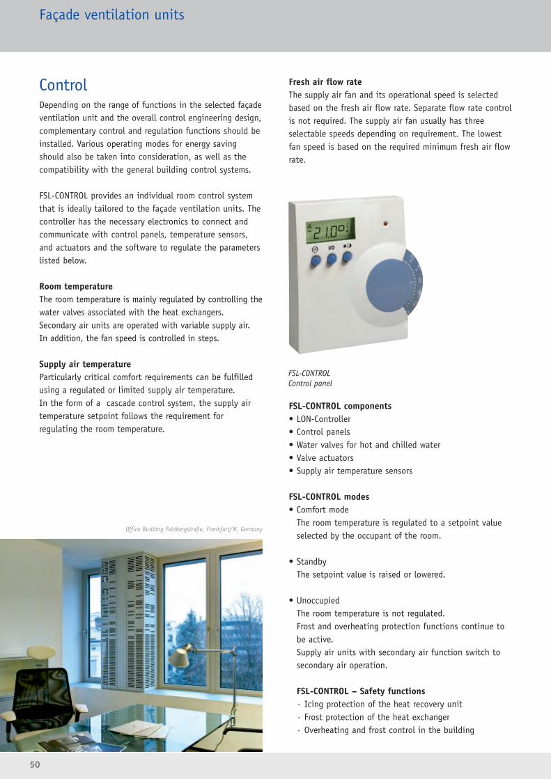
50
ControlDepending on the range of functions in the selected façadeventilation unit and the overall control engineering design,complementary control and regulation functions should beinstalled. Various operating modes for energy savingshould also be taken into consideration, as well as thecompatibility with the general building control systems.
FSL-CONTROL provides an individual room control systemthat is ideally tailored to the façade ventilation units. Thecontroller has the necessary electronics to connect andcommunicate with control panels, temperature sensors,and actuators and the software to regulate the parameterslisted below.
Room temperatureThe room temperature is mainly regulated by controlling thewater valves associated with the heat exchangers.Secondary air units are operated with variable supply air. In addition, the fan speed is controlled in steps.
Supply air temperatureParticularly critical comfort requirements can be fulfilledusing a regulated or limited supply air temperature. In the form of a cascade control system, the supply air temperature setpoint follows the requirement for regulating the room temperature.
Fresh air flow rateThe supply air fan and its operational speed is selectedbased on the fresh air flow rate. Separate flow rate controlis not required. The supply air fan usually has threeselectable speeds depending on requirement. The lowestfan speed is based on the required minimum fresh air flowrate.
FSL-CONTROL components• LON-Controller• Control panels• Water valves for hot and chilled water• Valve actuators• Supply air temperature sensors
FSL-CONTROL modes• Comfort mode
The room temperature is regulated to a setpoint valueselected by the occupant of the room.
• StandbyThe setpoint value is raised or lowered.
• Unoccupied The room temperature is not regulated. Frost and overheating protection functions continue tobe active. Supply air units with secondary air function switch tosecondary air operation.
FSL-CONTROL – Safety functions· Icing protection of the heat recovery unit· Frost protection of the heat exchanger· Overheating and frost control in the building
Façade ventilation units
FSL-CONTROLControl panel
Office Building Feldbergstraße, Frankfurt/M, Germany
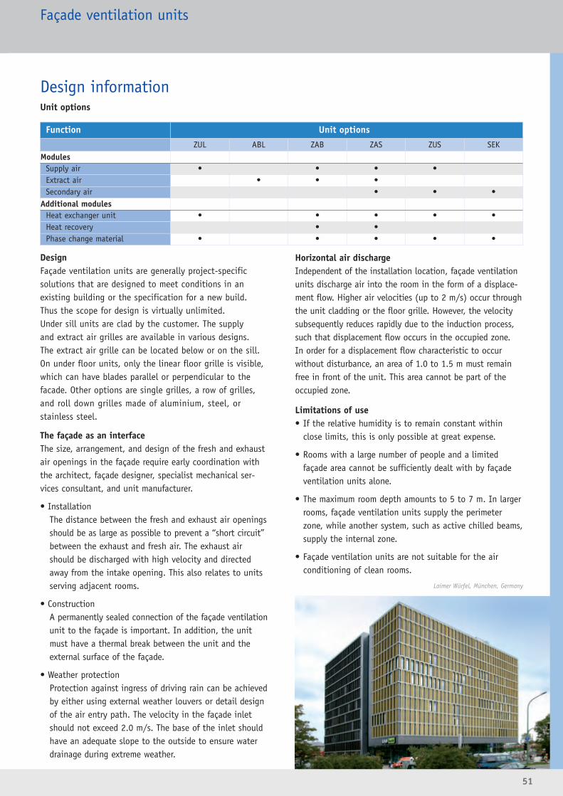
51
Function Unit options
ZUL ABL ZAB ZAS ZUS SEKModules
Supply air • • • •Extract air • • •Secondary air • • •
Additional modulesHeat exchanger unit • • • • •Heat recovery • •Phase change material • • • • •
Façade ventilation units
Design informationUnit options
DesignFaçade ventilation units are generally project-specificsolutions that are designed to meet conditions in an existing building or the specification for a new build. Thus the scope for design is virtually unlimited. Under sill units are clad by the customer. The supply and extract air grilles are available in various designs. The extract air grille can be located below or on the sill.On under floor units, only the linear floor grille is visible,which can have blades parallel or perpendicular to thefacade. Other options are single grilles, a row of grilles,and roll down grilles made of aluminium, steel, or stainless steel.
The façade as an interfaceThe size, arrangement, and design of the fresh and exhaustair openings in the façade require early coordination withthe architect, façade designer, specialist mechanical ser-vices consultant, and unit manufacturer.
• Installation The distance between the fresh and exhaust air openingsshould be as large as possible to prevent a “short circuit”between the exhaust and fresh air. The exhaust airshould be discharged with high velocity and directedaway from the intake opening. This also relates to unitsserving adjacent rooms.
• Construction A permanently sealed connection of the façade ventilationunit to the façade is important. In addition, the unitmust have a thermal break between the unit and theexternal surface of the façade.
• Weather protection Protection against ingress of driving rain can be achievedby either using external weather louvers or detail designof the air entry path. The velocity in the façade inletshould not exceed 2.0 m/s. The base of the inlet shouldhave an adequate slope to the outside to ensure waterdrainage during extreme weather.
Horizontal air dischargeIndependent of the installation location, façade ventilationunits discharge air into the room in the form of a displace -ment flow. Higher air velocities (up to 2 m/s) occur throughthe unit cladding or the floor grille. However, the velocitysubsequently reduces rapidly due to the induction process,such that displacement flow occurs in the occupied zone.In order for a displacement flow characteristic to occur without disturbance, an area of 1.0 to 1.5 m must remainfree in front of the unit. This area cannot be part of theoccupied zone.
Limitations of use• If the relative humidity is to remain constant within
close limits, this is only possible at great expense.
• Rooms with a large number of people and a limitedfaçade area cannot be sufficiently dealt with by façadeventilation units alone.
• The maximum room depth amounts to 5 to 7 m. In largerrooms, façade ventilation units supply the perimeterzone, while another system, such as active chilled beams,supply the internal zone.
• Façade ventilation units are not suitable for the air conditioning of clean rooms.
Laimer Würfel, München, Germany
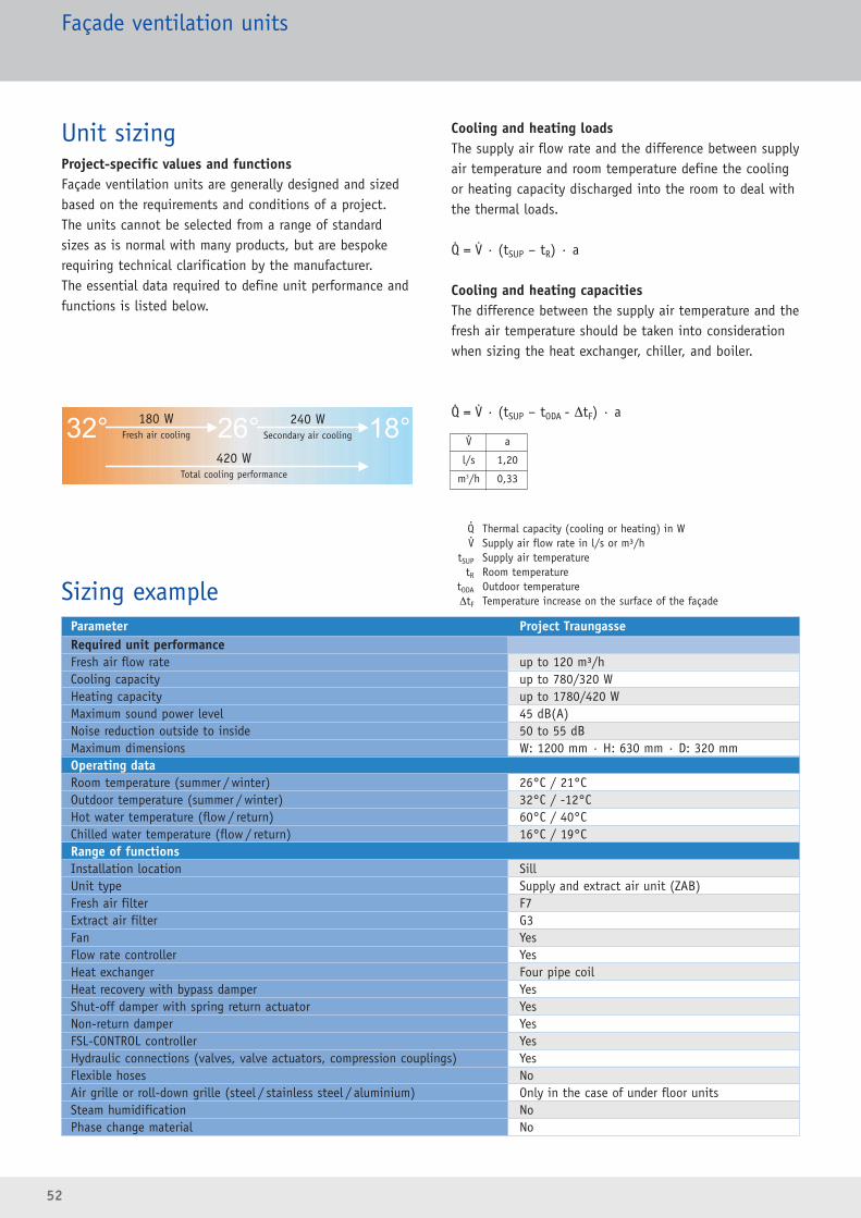
Unit sizingProject-specific values and functionsFaçade ventilation units are generally designed and sizedbased on the requirements and conditions of a project.The units cannot be selected from a range of standardsizes as is normal with many products, but are bespokerequiring technical clarification by the manufacturer.The essential data required to define unit performance andfunctions is listed below.
Cooling and heating loadsThe supply air flow rate and the difference between supplyair temperature and room temperature define the coolingor heating capacity discharged into the room to deal withthe thermal loads.
Q = V · (tSUP – tR) · a
Cooling and heating capacitiesThe difference between the supply air temperature and thefresh air temperature should be taken into considerationwhen sizing the heat exchanger, chiller, and boiler.
Q = V · (tSUP – tODA - ΔtF) · a
Q Thermal capacity (cooling or heating) in WV Supply air flow rate in l/s or m³/h
tSUP Supply air temperaturetR Room temperature
tODA Outdoor temperatureΔtF Temperature increase on the surface of the façade
52
Façade ventilation units
V a
l/s 1,20
m3/h 0,33
Parameter Project TraungasseRequired unit performanceFresh air flow rate up to 120 m³/hCooling capacity up to 780/320 WHeating capacity up to 1780/420 WMaximum sound power level 45 dB(A)Noise reduction outside to inside 50 to 55 dBMaximum dimensions W: 1200 mm · H: 630 mm · D: 320 mmOperating dataRoom temperature (summer / winter) 26°C / 21°COutdoor temperature (summer / winter) 32°C / -12°CHot water temperature (flow / return) 60°C / 40°CChilled water temperature (flow / return) 16°C / 19°CRange of functionsInstallation location SillUnit type Supply and extract air unit (ZAB)Fresh air filter F7Extract air filter G3Fan YesFlow rate controller YesHeat exchanger Four pipe coilHeat recovery with bypass damper YesShut-off damper with spring return actuator YesNon-return damper YesFSL-CONTROL controller YesHydraulic connections (valves, valve actuators, compression couplings) YesFlexible hoses NoAir grille or roll-down grille (steel / stainless steel / aluminium) Only in the case of under floor unitsSteam humidification NoPhase change material No
Sizing example
.
.
.
.
.
.
.
180 WFresh air cooling
240 WSecondary air cooling
420 WTotal cooling performance

53
Façade ventilation unitsUnder sill units
Type FSL-B-60
� Natural ventilation with good acoustic performance� Installation below or above a window or in walls� Uncontrolled ventilation� Manually operated air discharge control cylinder� Lined with thermal/acoustic material
W: 200 – 3000 mm · H: 60 mm · D: 140 – 600 mm3 – 42 l/s · 10 – 150 m³/h at 12 Pa differential pressure
Type FSL-B-100
� Natural or mechanical ventilation with good acoustic performance
� Project bespoke construction� Installation below, above or to the side of the window� Modular design:
Base casing for installation during construction phaseModular inserts for subsequent fitting
� Lined with thermal/acoustic material� Fine dust filter available
W: 1000 – 3000 mm · H: 100 mm · D: 230 – 600 mm8 – 22 l/s · 30 – 80 m³/h fresh air
Type FSL-B-190
� Mechanical ventilation with good acoustic performance� With heat recovery� Option with heat exchanger for heating and cooling� Under sill installation or installation under a window� Modular design:
Base casing for installation during construction phase Modular inserts for subsequent fitting
� Can also provide static heating
W: 1200 mm · H: 190 mm · D: 450 – 600 mm17 – 33 l/s · 60 – 120 m³/h fresh airCooling capacity up to 560 WHeating capacity up to 1735 W
In-flow or out-flow units
Type FSL-B-PCM� Supply air and recirculated secondary air modes possible� CO2-neutral cooling without refrigerants� With air heater� Project bespoke dimensions� Ideal for refurbishment
W: 1200 mm · H: 600 mm · D: 300 mmup to 42 l/s · up to 150 m³/h fresh airCooling capacity approx. 280 W when used for 5 hours Heating capacity up to 2000 W
Supply air units with phase change material
In-flow or out-flow unitsSupply or extract air units
Supply and extract air units (ZAB)
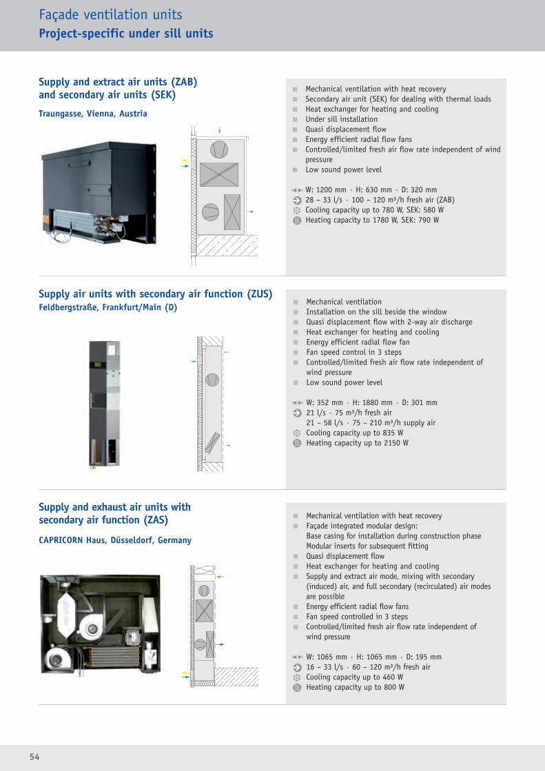
54
Façade ventilation unitsProject-specific under sill units
� Mechanical ventilation with heat recovery� Secondary air unit (SEK) for dealing with thermal loads� Heat exchanger for heating and cooling� Under sill installation� Quasi displacement flow� Energy efficient radial flow fans� Controlled/limited fresh air flow rate independent of wind
pressure� Low sound power level
W: 1200 mm · H: 630 mm · D: 320 mm28 – 33 l/s · 100 – 120 m³/h fresh air (ZAB)Cooling capacity up to 780 W, SEK: 580 WHeating capacity to 1780 W, SEK: 790 W
� Mechanical ventilation� Installation on the sill beside the window� Quasi displacement flow with 2-way air discharge� Heat exchanger for heating and cooling� Energy efficient radial flow fan� Fan speed control in 3 steps � Controlled/limited fresh air flow rate independent of
wind pressure� Low sound power level
W: 352 mm · H: 1880 mm · D: 301 mm 21 l/s · 75 m³/h fresh air21 – 58 l/s · 75 – 210 m³/h supply airCooling capacity up to 835 WHeating capacity up to 2150 W
� Mechanical ventilation with heat recovery� Façade integrated modular design:
Base casing for installation during construction phase Modular inserts for subsequent fitting
� Quasi displacement flow� Heat exchanger for heating and cooling� Supply and extract air mode, mixing with secondary
(induced) air, and full secondary (recirculated) air modes are possible
� Energy efficient radial flow fans� Fan speed controlled in 3 steps� Controlled/limited fresh air flow rate independent of
wind pressure
W: 1065 mm · H: 1065 mm · D: 195 mm16 – 33 l/s · 60 – 120 m³/h fresh airCooling capacity up to 460 WHeating capacity up to 800 W
CAPRICORN Haus, Düsseldorf, Germany
Supply air units with secondary air function (ZUS)Feldbergstraße, Frankfurt/Main (D)
Supply and exhaust air units with secondary air function (ZAS)
Supply and extract air units (ZAB)and secondary air units (SEK)
Traungasse, Vienna, Austria
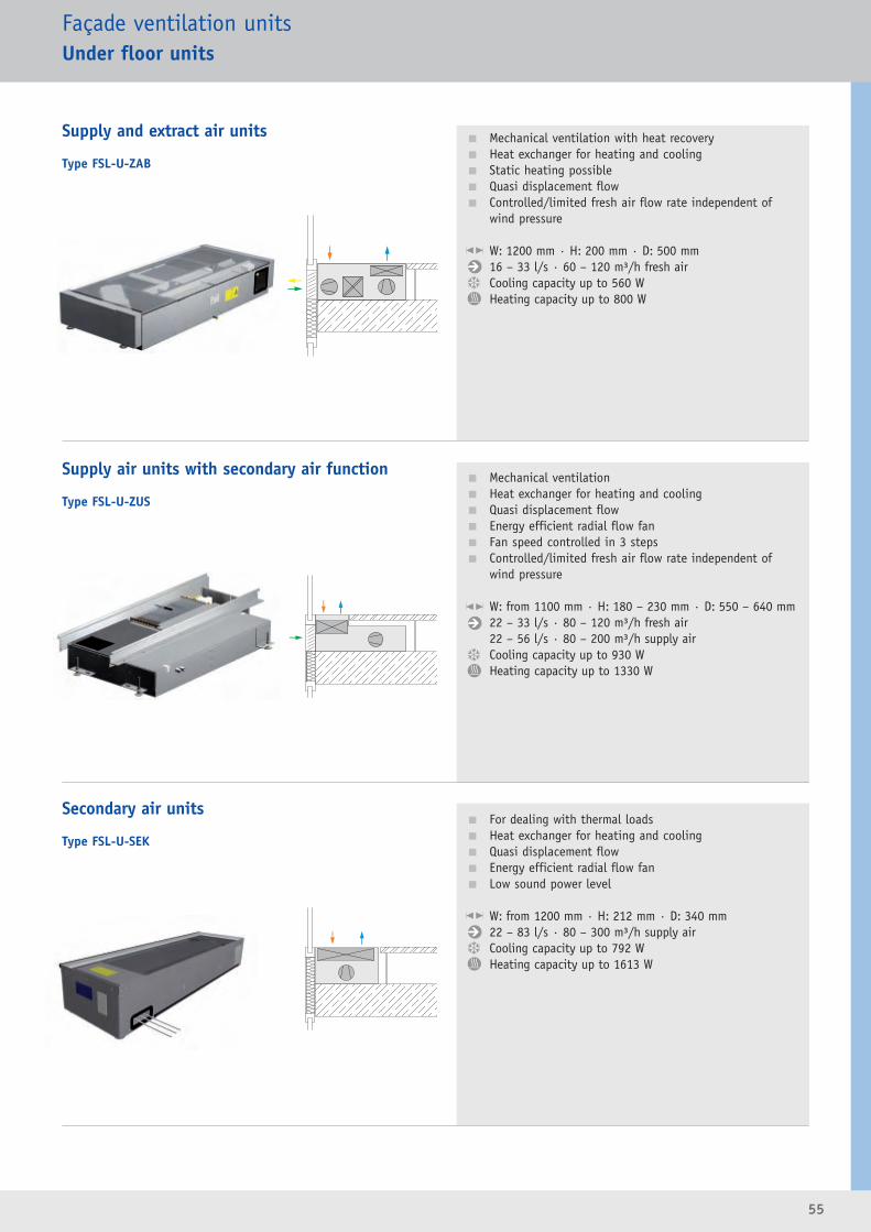
55
Façade ventilation unitsUnder floor units
� Mechanical ventilation with heat recovery� Heat exchanger for heating and cooling� Static heating possible� Quasi displacement flow� Controlled/limited fresh air flow rate independent of
wind pressure
W: 1200 mm · H: 200 mm · D: 500 mm16 – 33 l/s · 60 – 120 m³/h fresh airCooling capacity up to 560 WHeating capacity up to 800 W
� Mechanical ventilation� Heat exchanger for heating and cooling� Quasi displacement flow� Energy efficient radial flow fan� Fan speed controlled in 3 steps � Controlled/limited fresh air flow rate independent of
wind pressure
W: from 1100 mm · H: 180 – 230 mm · D: 550 – 640 mm22 – 33 l/s · 80 – 120 m³/h fresh air22 – 56 l/s · 80 – 200 m³/h supply airCooling capacity up to 930 WHeating capacity up to 1330 W
� For dealing with thermal loads� Heat exchanger for heating and cooling� Quasi displacement flow� Energy efficient radial flow fan� Low sound power level
W: from 1200 mm · H: 212 mm · D: 340 mm22 – 83 l/s · 80 – 300 m³/h supply airCooling capacity up to 792 WHeating capacity up to 1613 W
Type FSL-U-ZAB
Supply and extract air units
Type FSL-U-ZUS
Supply air units with secondary air function
Type FSL-U-SEK
Secondary air units
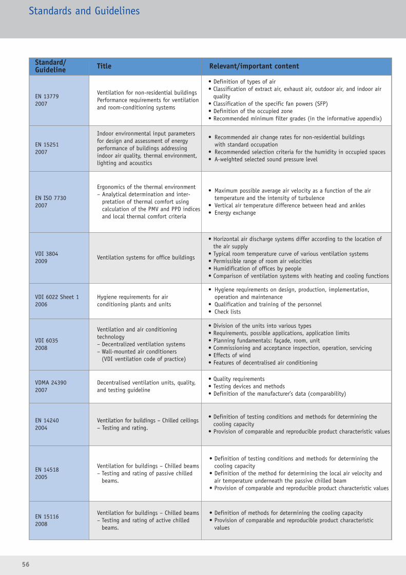
56
Standards and Guidelines
Standard/Guideline Title Relevant/important content
EN 137792007
Ventilation for non-residential buildingsPerformance requirements for ventilationand room-conditioning systems
• Definition of types of air• Classification of extract air, exhaust air, outdoor air, and indoor air
quality• Classification of the specific fan powers (SFP)• Definition of the occupied zone• Recommended minimum filter grades (in the informative appendix)
EN 152512007
Indoor environmental input parametersfor design and assessment of energy performance of buildings addressingindoor air quality, thermal environment,lighting and acoustics
• Recommended air change rates for non-residential buildings with standard occupation
• Recommended selection criteria for the humidity in occupied spaces• A-weighted selected sound pressure level
EN ISO 77302007
Ergonomics of the thermal environment – Analytical determination and inter -
pretation of thermal comfort using calculation of the PMV and PPD indicesand local thermal comfort criteria
• Maximum possible average air velocity as a function of the airtemperature and the intensity of turbulence
• Vertical air temperature difference between head and ankles• Energy exchange
VDI 38042009
Ventilation systems for office buildings
• Horizontal air discharge systems differ according to the location ofthe air supply
• Typical room temperature curve of various ventilation systems• Permissible range of room air velocities • Humidification of offices by people• Comparison of ventilation systems with heating and cooling functions
VDI 6022 Sheet 12006
Hygiene requirements for air conditioning plants and units
• Hygiene requirements on design, production, implementation, operation and maintenance
• Qualification and training of the personnel• Check lists
VDI 60352008
Ventilation and air conditioning technology– Decentralized ventilation systems– Wall-mounted air conditioners
(VDI ventilation code of practice)
• Division of the units into various types• Requirements, possible applications, application limits• Planning fundamentals: façade, room, unit • Commissioning and acceptance inspection, operation, servicing• Effects of wind• Features of decentralised air conditioning
VDMA 243902007
Decentralised ventilation units, quality,and testing guideline
• Quality requirements• Testing devices and methods• Definition of the manufacturer’s data (comparability)
EN 142402004
Ventilation for buildings – Chilled ceilings– Testing and rating.
• Definition of testing conditions and methods for determining the cooling capacity
• Provision of comparable and reproducible product characteristic values
EN 145182005
Ventilation for buildings – Chilled beams – Testing and rating of passive chilled
beams.
• Definition of testing conditions and methods for determining the cooling capacity
• Definition of the method for determining the local air velocity and air temperature underneath the passive chilled beam
• Provision of comparable and reproducible product characteristic values
EN 151162008
Ventilation for buildings – Chilled beams– Testing and rating of active chilled
beams.
• Definition of methods for determining the cooling capacity• Provision of comparable and reproducible product characteristic
values
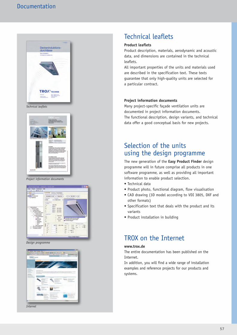
57
Documentation
Technical leafletsProduct leafletsProduct description, materials, aerodynamic and acousticdata, and dimensions are contained in the technicalleaflets.All important properties of the units and materials usedare described in the specification text. These texts guarantee that only high-quality units are selected for a particular contract.
Project information documentsMany project-specific façade ventilation units are documented in project information documents. The functional description, design variants, and technicaldata offer a good conceptual basis for new projects.
Selection of the units using the design programmeThe new generation of the Easy Product Finder designprogramme will in future comprise all products in onesoftware programme, as well as providing all important information to enable product selection.• Technical data• Product photo, functional diagram, flow visualisation• CAD drawing (3D model according to VDI 3805, DXF and
other formats)• Specification text that deals with the product and its
variants• Product installation in building
TROX on the Internetwww.trox.deThe entire documentation has been published on theInternet.In addition, you will find a wide range of installation examples and reference projects for our products andsystems.
Technical leaflets
Project information documents
Design programme
Internet
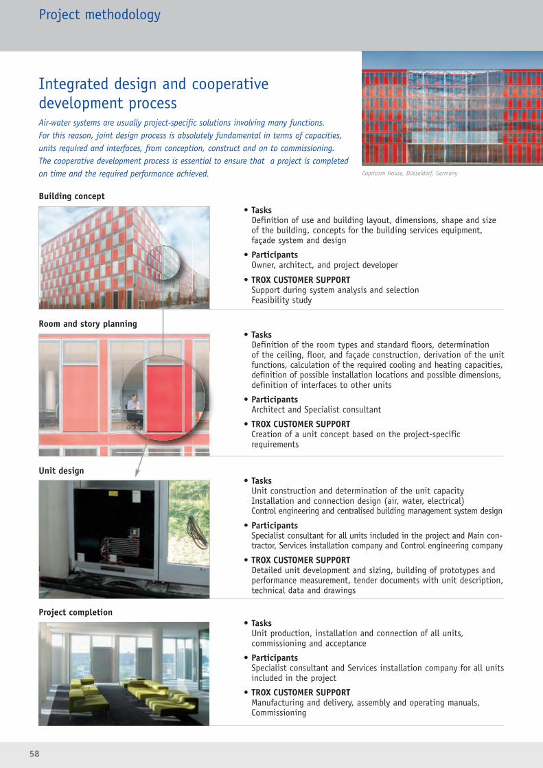
• TasksDefinition of use and building layout, dimensions, shape and sizeof the building, concepts for the building services equipment,façade system and design
• ParticipantsOwner, architect, and project developer
• TROX CUSTOMER SUPPORTSupport during system analysis and selection Feasibility study
• TasksDefinition of the room types and standard floors, determination of the ceiling, floor, and façade construction, derivation of the unitfunctions, calculation of the required cooling and heating capacities,definition of possible installation locations and possible dimensions, definition of interfaces to other units
• ParticipantsArchitect and Specialist consultant
• TROX CUSTOMER SUPPORTCreation of a unit concept based on the project-specific requirements
• TasksUnit construction and determination of the unit capacity Installation and connection design (air, water, electrical)Control engineering and centralised building management system design
• ParticipantsSpecialist consultant for all units included in the project and Main con-tractor, Services installation company and Control engineering company
• TROX CUSTOMER SUPPORTDetailed unit development and sizing, building of prototypes andperformance measurement, tender documents with unit description,technical data and drawings
• TasksUnit production, installation and connection of all units, commissioning and acceptance
• ParticipantsSpecialist consultant and Services installation company for all unitsincluded in the project
• TROX CUSTOMER SUPPORTManufacturing and delivery, assembly and operating manuals,Commissioning
58
Project methodology
Integrated design and cooperative development processAir-water systems are usually project-specific solutions involving many functions. For this reason, joint design process is absolutely fundamental in terms of capacities,units required and interfaces, from conception, construct and on to commissioning.The cooperative development process is essential to ensure that a project is completedon time and the required performance achieved. Capricorn House, Düsseldorf, Germany
Building concept
Room and story planning
Unit design
Project completion

59
Air/water systemsReferences
Post Tower, Bonn, Germany
European Investment Bank, Luxembourg
City of Justice, Barcelona, Spain
Constitution Center, Washington, DC, USA
IBC, Frankfurt, Germany
AluBrixen, Italy
Antwerp TowerAntwerp, Belgium
BusbahnhofUnna, Germany
Capricorn HouseDüsseldorf, Germany
Chambre de CommerceLuxembourg, Luxembourg
City of JusticeBarcelona, Spain
Constitution CenterWashington, USA
Daimler ChryslerSindelfingen, Germany
DEG ZentraleKöln, Germany
Dexia BILLuxembourg, Luxembourg
EBH BankDenmark
European Investment BankLuxembourg, Luxembourg
FeldbergstraßeFrankfurt am Main, Germany
Greater London AuthorityLondon, Great Britain
HelveaZürich, Switzerland
Investment Banking CentreFrankfurt am Main, Germany
Imtech HausHamburg, Germany
KIAFrankfurt am Main, Germany
Laimer WürfelMünchen, Germany
Mannheimer InsuranceMannheim, Germany
Messehalle 3Frankfurt am Main, Germany
Messehalle 11Frankfurt am Main, Germany
MessezentrumSalzburg, Austria
MigrosGenf, Switzerland
Mondrian EU-AdministrationBuildingBrüssel, Belgium
NeumühlequaiZürich, Switzerland
NestléVevey, Switzerland
Post TowerBonn, Germany
Office am SeeBregenz, Austria
Paul Scherrer InstitutVillingen, Switzerland
RAMADA HotelSolothurn, Switzerland
Swiss Post OfficeChur, Switzerland
Norwich Union HQNorwich, Great Britain
SKYLINK FlughafenWien, Austria
Sky OfficeDüsseldorf, Germany
St. Phillips AcademyNew Jersey, USA
SwarovskiWattens, Austria
TelefónicaMadrid, Spain
Thuringia InsuranceMünchen, Germany
TraungasseWien, Austria
UniversityAmsterdam, Netherlands
UniversityFribourg, Switzerland
University HospitalZürich, Switzerland
WHG-BürgleinstraßeMünchen, Germany

S/LW
S/EN
/2 (
10/2
009)
�TR
OX G
mbH
Headquarters GermanyTROX GmbH Phone +49(0)28 45 / 2 02-0Heinrich-Trox-Platz Fax +49(0)28 45 / 2 02-2 65
E-Mail [email protected] Neukirchen-Vluyn www.troxtechnik.com
Subsidiaries and Sales OfficesArgentinaTROX Argentina S.A.AustraliaTROX Australia Pty LtdAustriaTROX Austria GmbHBelgiumS.A. TROX Belgium N.V.BrazilTROX do Brasil Ltda.BulgariaTROX Austria GmbHChinaTROX Air Conditioning Components(Suzhou) Co., Ltd.CroatiaTROX Austria GmbHCzech RepublicTROX Austria GmbHDenmarkTROX Danmark A/S
FranceTROX France SarlGermanyFSL GmbH & Co. KGTROX Deutschland GmbHTROX Filter GmbHGreat BritainTROX UK Ltd.TROX AITCS Ltd.Hong KongTROX Hong Kong Ltd.TROX AITCS Ltd.HungaryTROX Austria GmbHIndiaTROX INDIA PRIVATE LIMITEDItalyTROX Italia S.p.A.MalaysiaTROX Malaysia Sdn. Bhd.NorwayTROX Auranor Norge AS
PolandTROX Austria GmbHRomaniaTROX Austria GmbHRussiaOOO TROX RUSSerbiaTROX Austria GmbHSouth AfricaTROX South Africa (Pty) LtdSpainTROX España, S.A.SwedenTROX Sverige ABSwitzerlandTROX HESCO Switzerland AGUnited Arab EmiratesTROX Middle East (LLC)USATROX USA, Inc.TROX AITCS Ltd.
International RepresentativesAbu DhabiBosnia-HerzegovinaChileCyprusEgyptFinlandGreece
IcelandIndonesiaIranIrelandIsraelJordanKorea
LatviaLebanonLithuaniaMexicoMoroccoNetherlandsNew Zealand
OmanPakistanPhilippinesPortugalSaudi ArabiaSlovak RepublicSlovenia
SwedenTaiwanThailandTurkeyUkraineUruguayVenezuela
VietnamZimbabwe