ype t jz-rs - trox
TRANSCRIPT

JZ-RS with AS-i module
Smoke protection dam per, Type JZ-RS,with installation subframe
JZ-RS with actuator
With TROXNETCOMas an option
Smoke protection dampers Type JZ-RS
2
Smoke protection dampers are used in ventilation plant roomsor in ducts to prevent smoke from spreading
■ Casing air leakage to EN 1751, class C ■ Low differential pressure and sound power level ■ Airflow direction is not critical ■ Available in standard sizes and many intermediate sizes
Optional equipment and accessories ■ Duct smoke detector RM-O-VS-D or RM-O-3-D ■ Installation subframe ■ Integration into the central BMS with TROXNETCOM
JZ-RS 2.1 –
X X JZ-RS testregistrierung
K 4 – 2.1 – 1
To prevent the spreading of smoke
06/2015 – DE/en

Smoke protection dampers General information JZ-RS
2
Type
JZ-RS General information 2.1 – 2Order code 2.1 – 5Attachments 2.1 – 6Installation subframe 2.1 – 11Installation details 2.1 – 13Quick sizing 2.1 – 14Technical data 2.1 – 15Dimensions and weight 2.1 – 16Dimensions – Duct connection 2.1 – 18Specification text 2.1 – 19
Basic information and nomenclature 2.2 – 1
Page
K 4 – 2.1 – 2
Variants
Product examples
Smoke protection damper with actuator,flange holes on both sides
JZ-RS with AS-i module
Smoke protection damper JZ-RS-Gwith actuator
JZ-RS-G-R with installation subframe
06/2015 – DE/en

Smoke protection dampers General information JZ-RS
2
Application– Smoke protection dampers of Type JZ-RS are used in ventilation plant rooms or in ducts
to prevent smoke from spreading (according to the German guideline regarding fire protection requirements on ventilation systems, LüAR)
– For the refurbishment of systems with regard to fire safety– Can be triggered by duct smoke detectors with general building inspectorate licence– Integration into the central BMS with TROXNETCOM
Classification– Building inspectorate licence Z-78.4-51 from the DIBt, Berlin, Germany– Casing air leakage to EN 1751, class C– Closed blade air leakage at a differential
pressure of 40 Pa = 200 m³/h per m²– Long-term testing: 10,000 open/close cycles
Construction– Galvanised sheet steel, corner holes on both sides, brass bearings– G: Flange holes on both sides
Nominal sizes– Standard: B = 400 – 2000 mm (in increments of 200 mm), H = 345 – 1995 mm (in increments of 165 mm)– R20 sizes: B = 357 – 1998 mm (in R20 increments), H = 357 – 1998 mm (in R20er increments)
Attachments– Installation subframe ER– Smoke detector– TROXNETCOM
Special characteristics– Low differential pressure and sound power level– Aerofoil blades– Low-maintenance, robust construction– No parts with silicone– Available in standard sizes and many intermediate sizes– Closed cell side seals meet increased hygiene requirements
Parts and characteristics– Frame– Blade– Spring return actuator– External linkage– Travel stop (angle section), side B– Side seal, side H
Construction features– Rectangular casing, welded, material thickness 1.25 mm– Blades, material thickness 1 mm, opposed action– Flanges on both sides, suitable for duct connection, either flange holes or corner holes– Spring return actuator on the 2nd blade (for all sizes)– Control input signal from the central BMS or TROXNETCOM– External linkage, robust and durable, consisting
of the coupling rod and and horizontal arms– Blade shafts, Ø12 mm, with notch to indicate the blade position– Construction and materials comply with the EU directive and guidelines for use in potentially explosive atmospheres (ATEX)– Side seals between the regular blades and the frame– Travel stop (angle section) ensures tight
closure of the top and bottom blades
Materials and surfaces– Casing, blades and travel stop (angle section)
made of formed galvanised sheet steel; flanges on both sides with corner holes– Blade shafts, drive arm and external linkage
made of galvanised steel– Side seal made of stainless steel– Brass bearings
Installation and commissioning– Installation position is independent of the airflow direction– With horizontal blades– Between ducts– On walls and ceilings (with installation subframe)– With or without installation subframe– Torsion-free installation– After installation the damper must remain
accessible for inspection, cleaning and repair– Connected ducts must have an inspection access
Standards and guidelines– German 'Bau- und Prüfgrundsätze' [Principles of Construction and Testing], 2/84 edition– Maintenance standards DIN 31051 and EN 13305
Maintenance– Smoke protection dampers and duct smoke
detectors must be maintained regularly and must be operational at all times– To maintain the normal function of the unit, or to re-instate its normal function,
maintenance standards DIN 31051 and EN 13305 must be complied with– Smoke protection dampers must be maintained at least every 12 months– A maintenance report must be created;
documents must be kept for reference– Maintenance-free as construction and materials are not subject to wear
K 4 – 2.1 – 3
Description
Smoke protectiondamper of Type JZ-RS
06/2015 – DE/en
Smoke protection dampers General information JZ-RS
2
K 4 – 2.1 – 4
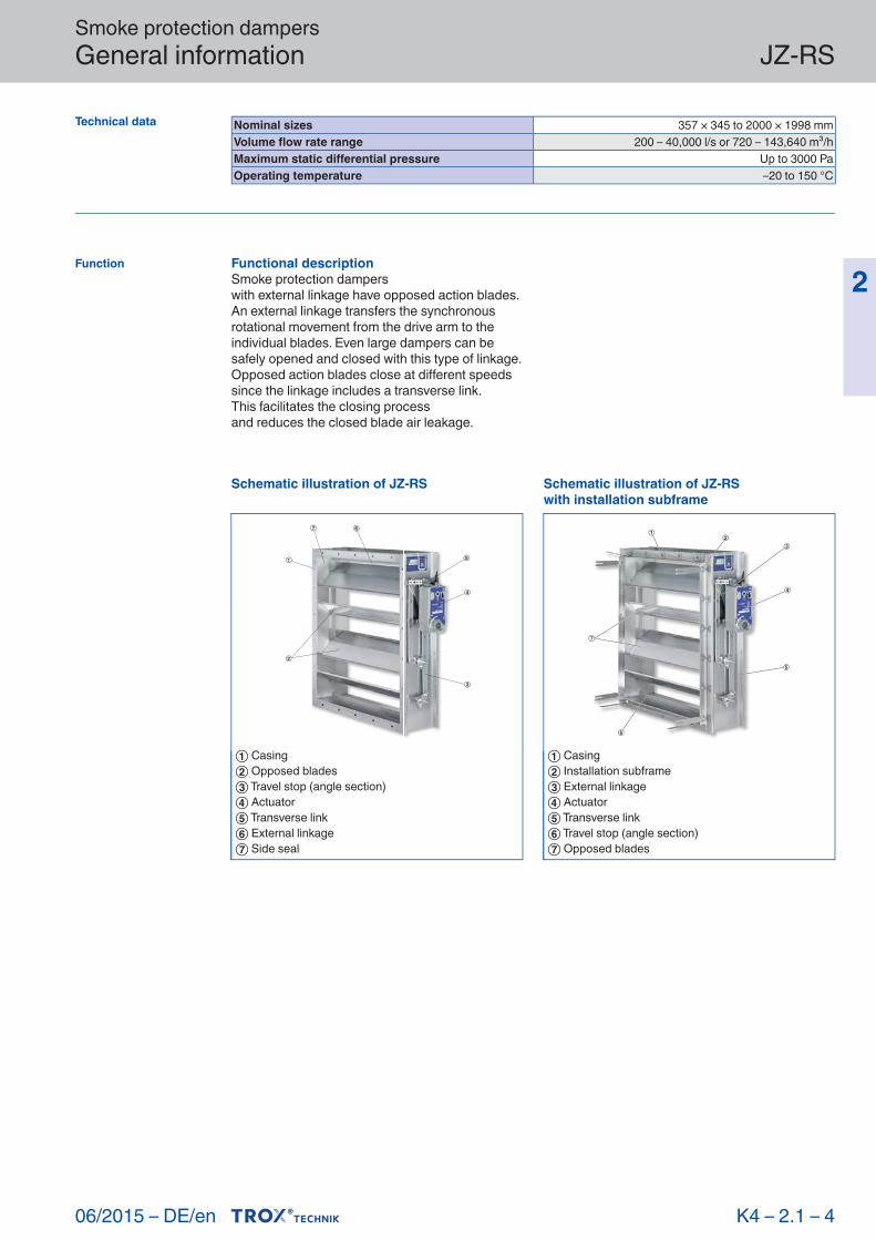
Technical data Nominal sizes 357 × 345 to 2000 × 1998 mmVolume flow rate range 200 – 40,000 l/s or 720 – 143,640 m³/hMaximum static differential pressure Up to 3000 PaOperating temperature –20 to 150 °C
06/2015 – DE/en
Functional descriptionSmoke protection damperswith external linkage have opposed action blades.An external linkage transfers the synchronous rotational movement from the drive arm to the individual blades. Even large dampers can be safely opened and closed with this type of linkage.Opposed action blades close at different speeds since the linkage includes a transverse link.This facilitates the closing processand reduces the closed blade air leakage.
Function
Schematic illustration of JZ-RS
① Casing② Opposed blades③ Travel stop (angle section)④ Actuator⑤ Transverse link⑥ External linkage⑦ Side seal
Schematic illustration of JZ-RSwith installation subframe
① Casing② Installation subframe③ External linkage④ Actuator⑤ Transverse link⑥ Travel stop (angle section)⑦ Opposed blades

Smoke protection dampers Order code JZ-RS
2
K 4 – 2.1 – 5
Order example
JZ-RS
JZ – RS – G – R / 1000×1005 / ER / ZF06
TypeJZ-RS Smoke protection damper
ConstructionNo entry: standard construction
G Flange holes on both sides
Drive sideR Right sideL Left side
(If the drive side is not specifiedwith the order, R will be supplied.)
Nominal size [mm]B × H
Installation subframeNo entry: none
ER With (only for construction G)
AttachmentsSpring return actuator (power off to close), IP 54ZF06 24 V AC / DCZF07 24 – 240 V AC ZF08 24 V AC / DC, with limit switches ZF09 24 – 240 V AC , with limit switchesZF10 24 V AC / DC with control actuator
Order code
JZ-RS-G-L/600x1500/ER/ZF10Construction Flange holes on both sidesDrive side Left sideNominal size 600 × 1500 mmInstallation subframe WithAttachments Spring return actuator, actuator without spring return SF24A-SR, power off to close
06/2015 – DE/en

Smoke protection dampers Attachments JZ-RS
2
/ ZF06 / N...
Order code detail
Application– Spring return actuator SF24A– Opening and closing with safety function– Safety position of the smoke protection
damper: NC (power off to close)
Parts and characteristics– Supply voltage 24 V AC/DC– Control input signal: Supply voltage on/off– Mechanical stops
Description
K 4 – 2.1 – 6
Technical data
Actuator SF24A
Wiring
Actuator SF24ASupply voltage (AC) 24 V AC ± 20 %, 50/60 HzSupply voltage (DC) 24 V DC –10 %, +20 %Power rating (AC) 7 VA max.Power rating (DC) 5 W max.Torque 20 NmMotor running time for 90° < 75 sSpring return time 20 s (for < −20 °C up to 60 s)Control input signal Supply voltage on/offConnecting cable 2 × 0.75 mm², 1 m longIEC protection class III (protective extra-low voltage)Protection level IP 54EC conformity EMC according to 2004/108/ECOperating temperature –30 to 50 °CWeight 2.1 kg
Connecting cable core identification
~+
SF24A
BK RD
1 2
1 ⊥, –: Ground, neutral2 ~, +: Control voltage for direction of rotation 1
06/2015 – DE/en
Smoke protection dampers Attachments JZ-RS
2
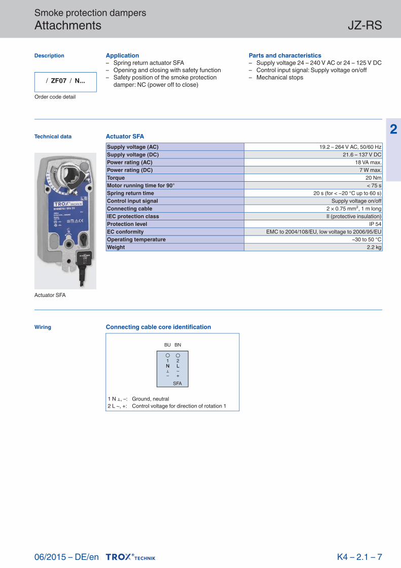
/ ZF07 / N...
Order code detail
Application– Spring return actuator SFA– Opening and closing with safety function– Safety position of the smoke protection
damper: NC (power off to close)
Parts and characteristics– Supply voltage 24 – 240 V AC or 24 – 125 V DC– Control input signal: Supply voltage on/off– Mechanical stops
Description
K 4 – 2.1 – 7
Technical data
Actuator SFA
Wiring
Actuator SFASupply voltage (AC) 19.2 – 264 V AC, 50/60 HzSupply voltage (DC) 21.6 – 137 V DCPower rating (AC) 18 VA max.Power rating (DC) 7 W max.Torque 20 NmMotor running time for 90° < 75 sSpring return time 20 s (for < −20 °C up to 60 s)Control input signal Supply voltage on/offConnecting cable 2 × 0.75 mm², 1 m longIEC protection class II (protective insulation)Protection level IP 54EC conformity EMC to 2004/108/EU, low voltage to 2006/95/EUOperating temperature –30 to 50 °CWeight 2.2 kg
Connecting cable core identification
NN~+
LL
SFA
BU BN
1 2
1 N ⊥, –: Ground, neutral2 L ~, +: Control voltage for direction of rotation 1
06/2015 – DE/en

Smoke protection dampers Attachments JZ-RS
2
/ ZF08 / N...
Order code detail
Application– Spring return actuator SF24A-S2 with integral auxiliary switches– Opening and closing with safety function– Safety position of the smoke protection
damper: NC (power off to close)
Parts and characteristics– Supply voltage 24 V AC/DC– Control input signal: Supply voltage on/off– Mechanical stops– Two auxiliary switches with volt-free contacts
for signalling or activating switch functions– Fixed auxiliary switch, switching point 10 %– Adjustable auxiliary switch, switching point 10 – 90 %
Description
K 4 – 2.1 – 8
Technical data
Actuator SF24A-S2
Wiring
Actuator SF24A-S2Supply voltage (AC) 24 V AC ± 20 %, 50/60 HzSupply voltage (DC) 24 V DC ±10 %Power rating (AC) 7.5 VA max.Power rating (DC) 5 W max.Torque 20 NmMotor running time for 90° < 75 sSpring return time 20 s (< −20 °C max. 60 s)Control input signal Supply voltage on/offAuxiliary switch: type of contact 2 changeover contacts 1)
Max. switching voltage (AC) 250 V AC Max. switching current (AC) 3 A (resistive load); 0.5 A (inductive load)Max. switching voltage (DC) 110 V DCMax. switching current (DC) 0.5 A (resistive load); 0.2 A (inductive load) Connecting cable – actuator 2 × 0.75 mm², 1 m longConnecting cable – auxiliary switch 6 × 0.75 mm², 1 m longIEC protection class III (protective extra-low voltage)Protection level IP 54EC conformity EMC to 2004/108/EU, low voltage to 2006/95/EUOperating temperature –30 to 50 °CWeight 2.3 kg
1) If both auxiliary switches are used the switching voltages must be the same
Connecting cable core identification
~
SF24A-S2
21
+
BK RD VT RD WH OG PK GY
S1 S2 S3 S6S5S4
1 ⊥, –: Ground, neutral2 ~, +: Control voltage for direction of rotation 1S1: Common contactS2: Mechanical stop 1 < xS3: Mechanical stop 1 > xS4: Common contactS5: Mechanical stop 2 < yS6: Mechanical stop 2 > yx: 10 %y: 10 ... 90 %
06/2015 – DE/en

Smoke protection dampers Attachments JZ-RS
2
/ ZF09 / N...
Order code detail
Application– Spring return actuator SFA-S2 with integral auxiliary switches– Opening and closing with safety function– Safety position of the smoke protection
damper: NC (power off to close)
Parts and characteristics– Supply voltage 24 – 240 V AC or 24 – 125 V DC– Control input signal: Supply voltage on/off– Mechanical stops– Two auxiliary switches with volt-free contacts
for signalling or activating switch functions– Fixed auxiliary switch, switching point 10 %– Adjustable auxiliary switch, switching point 10 – 90 %
Description
K 4 – 2.1 – 9
Technical data
Actuator SFA-S2
Wiring
Spring return actuator SFA-S2Supply voltage (AC) 19.2 – 264 V AC, 50/60 HzSupply voltage (DC) 21.6 – 137 V DCPower rating (AC) 18 VA max.Power rating (DC) 7 W max.Torque 20 NmMotor running time for 90° < 75 sSpring return time 20 s (< −20 °C max. 60 s)Control input signal Supply voltage on/offAuxiliary switch: type of contact 2 changeover contacts 1)
Max. switching voltage (AC) 250 V AC Max. switching current (AC) 3 A (resistive load); 0.5 A (inductive load)Max. switching voltage (DC) 110 V DCMax. switching current (DC) 0.5 A (resistive load); 0.2 A (inductive load) Connecting cable – actuator 2 × 0.75 mm², 1 m longConnecting cable – auxiliary switch 6 × 0.75 mm², 1 m longIEC protection class II (protective insulation)Protection level IP 54EC conformity EMC to 2004/108/EU, low voltage to 2006/95/EUOperating temperature –30 to 50 °CWeight 2.4 kg
1) If both auxiliary switches are used the switching voltages must be the same
Connecting cable core identification
~
SFA-S2
21
+
BU BN VT RD WH OG PK GY
S1 S2 S3 S6S5S4LN
1 ⊥, –: Ground, neutral2 ~, +: Control voltage for direction of rotation 1S1: Common contactS2: Mechanical stop 1 < xS3: Mechanical stop 1 > xS4: Common contactS5: Mechanical stop 2 < yS6: Mechanical stop 2 > yx: 10 %y: 10 ... 90 %
06/2015 – DE/en

Smoke protection dampers Attachments JZ-RS
2
/ ZF10 / NC
Order code detail
Application– Spring return actuator SF24A-SR– Stepless adjustment as well as opening and closing of smoke protection dampers with safety function– Safety position of the smoke protection
damper: NC (power off to close)
Parts and characteristics– Supply voltage 24 V AC/DC– Control input signal: Setpoint value signal
2 – 10 V DC, corresponds to the total rotation range (90°), working range is limited
by mechanical stops– Output: Actual value signal 2 – 10 V– Mechanical stops
Description
K 4 – 2.1 – 10
Technical data
Actuator SF24A-SR
Wiring
Actuator SF24A-SRSupply voltage (AC) 24 V AC –10 %, + 20 %, 50/60 HzSupply voltage (DC) 24 V DC ± 20 %Power rating (AC) 7 VA max.Power rating (DC) 5 W max.Torque 20 NmMotor running time for 90° 150 sSpring return 20 s (for < −20 °C up to 60 s)Control signal 2 – 10 V DC, Ra > 100 kΩConnecting cable 4 × 0.75 mm², 1 m longIEC protection class III (protective extra-low voltage)Protection level IP 54EC conformity EMC according to 2004/108/ECOperating temperature –30 to 50 °CWeight 2.1 kg
Connecting cable core identification
~
SF24A-SR
2 31
+Y U
5
BK RD WH OG
1 ⊥, –: Ground, neutral2 ~, +: Supply voltage3 Y: Setpoint value signal4 U: Actual value signal
06/2015 – DE/en

Smoke protection dampers Installation subframe JZ-RS
2
Smoke protection damper, Type JZ-RS,with installation subframe
... / ER / ...
Order code detail
Application– For the installation of smoke protection damper
on walls and ceilings– Simplified installation– The installation subframe allows for the fast,
simple and precise installation of smoke protection damper
Materials and surfacesJZ-RS– Installation subframe made of galvanised steel
(angle section 35 × 35 × 3 mm)– Screw-on fixing tabs, threaded studs, screws, nuts and washers made of galvanised steel
Parts and characteristics– Installation subframe consisting of angle sections– Threaded studs– Washers– Hexagon nuts– Fixing tabs
Description
Any accessoriesare defined withthe order code of the smoke protection damper.
K 4 – 2.1 – 11 06/2015 – DE/en
Installation subframe for multileaf dampers and for smoke protection dampers
① Threaded stud② Washer③ Hexagon nut④ Fixing tab⑤ Hexagon head screw⑥ Installation subframe

Smoke protection dampers Installation subframe JZ-RS
2
K 4 – 2.1 – 12
Before the subframe is mortared in, the fixing tabs must be bent and spread (by others).
Installation subframe ready to be mortared in
B
H
H +
70
35
X
B + 70X
Installation subframe for JZ-RS
H +
20
B +
20
HB
Detail DD
① Threaded stud② Fixing tab
③ Installation subframe
06/2015 – DE/en

Smoke protection dampers Installation details JZ-RS
2
K 4 – 2.1 – 13
Installation on the face of walls or ceilings with installation subframe
① Duct② JZ-RS③ Fixing tab④ Mortar⑤ Installation subframe⑥ External weather louvre (optional)⑦ Wall
Installation in non-combustible ducts
① Duct② JZ-RS
Installation on the face of walls or ceilings
① Duct② JZ-RS③ Wall
06/2015 – DE/en
Smoke protection dampers Quick sizing JZ-RS
2
K 4 – 2.1 – 14
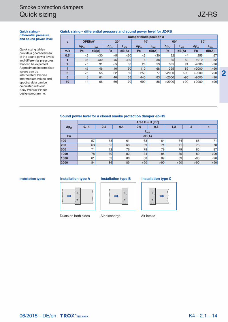
Quick sizing – differen tial pressure and sound power level
Quick sizing tables provide a good overview of the sound power levels and differential pressures that can be expected. Approximate intermediate values can be interpolated. Precise intermediate values and spectral data can be calculated with ourEasy Product Finder design programme.
Installation types
Sound power level for a closed smoke protection damper JZ-RS
Δpst
Area B × H [m²]0.14 0.2 0.4 0.6 0.8 1.2 2 4
LWA
Pa dB(A)100 57 58 61 63 64 64 68 71200 63 65 68 69 71 71 75 78500 71 72 76 78 79 79 85 871000 78 80 82 84 85 85 89 >901500 81 82 86 88 89 89 >90 >902000 84 86 89 >90 >90 >90 >90 >90
Quick sizing – differential pressure and sound power level for JZ-RS
vDamper blade position α
OPEN/0° 20° 40° 60° 80°Δpst LWA Δpst LWA Δpst LWA Δpst LWA Δpst LWA
m/s Pa dB(A) Pa dB(A) Pa dB(A) Pa dB(A) Pa dB(A)0.5 <5 <30 <5 <30 <5 <30 22 44 255 671 <5 <30 <5 <30 8 38 85 59 1010 822 <5 31 <5 35 28 53 335 74 >2000 >904 <5 46 10 50 110 68 1395 89 >2000 >906 <5 55 22 59 250 77 >2000 >90 >2000 >908 8 61 40 65 440 83 >2000 >90 >2000 >90
10 14 66 60 70 690 88 >2000 >90 >2000 >90
Ducts on both sides Air discharge Air intake
Installation type A Installation type B Installation type C
06/2015 – DE/en

Smoke protection dampers Technical data JZ-RS
2
K 4 – 2.1 – 15
Free area Free area, standard sizes of smoke protection damper JZ-RS
HB [mm]
400 600 800 1000 1200 1400 1600 1800mm m²
345 0.11 0.17 0.23 0.28 0.34 0.40 0.45 0.51510 0.17 0.25 0.33 0.42 0.50 0.58 0.67 0.75675 0.22 0.33 0.44 0.55 0.66 0.77 0.88 0.99840 0.27 0.41 0.55 0.69 0.82 0.96 1.10 1.231005 0.33 0.49 0.66 0.82 0.98 1.15 1.31 1.471170 0.38 0.57 0.76 0.95 1.14 1.33 1.52 1.721335 0.43 0.65 0.87 1.09 1.30 1.52 1.74 1.961500 0.49 0.73 0.98 1.22 1.47 1.71 1.95 2.201665 0.54 0.81 1.08 1.36 1.63 1.90 2.17 2.441830 0.60 0.89 1.19 1.49 1.79 2.08 2.38 2.681995 0.65 0.97 1.30 1.62 1.95 2.27 2.60 2.92Intermediate sizes: Intermediate widths can be interpolated
Maximum static differential pressure for a closed smoke protection damper
ConstructionWidth [mm]
800 1000 1200 1400 1600 1800 2000[Pa]
Standard construction 3000 2500 2200 1950 1750 1600 1500
The pressures given are independent of the height of the smoke protection damper
06/2015 – DE/en

Smoke protection dampers Dimensions and weight JZ-RS
2
K 4 – 2.1 – 16
Dimensions
Smoke protection damper JZ-RS-G with actuator
Weights (incl. actuator)
HB [mm]
400 600 800 1000 1200 1400 1600 1800 2000mm kg345 13 15 17 20 22 24 26 29 31510 15 18 21 24 27 30 32 35 38675 18 21 25 28 32 35 38 42 45840 20 24 28 33 37 42 46 51 55
1005 22 27 32 37 43 48 53 58 641170 24 30 36 42 48 54 60 66 721335 27 33 40 46 53 60 66 73 791500 28 35 42 49 56 64 71 78 851665 30 38 46 54 62 70 77 85 931830 32 40 49 57 66 74 83 91 1001995 34 43 52 61 71 80 89 99 108
JZ-RS standard sizes
H No. of bladesActuator position
X Blademm – mm –345 2 255 2510 3 255 2675 4 255 2840 5 255 2
1005 6 255 21170 7 255 21335 8 255 21500 9 255 21665 10 255 21830 11 255 21995 12 255 2
Illustration shows smoke protection damper with spring return actuator, operating side on the right
JZ-RS Standard sizes
B
H
180 3890
165
X
06/2015 – DE/en

Smoke protection dampers Dimensions and weight JZ-RS
2
K 4 – 2.1 – 17
Dimensions
JZ-RSintermediate sizes
H No. of bladesActuator position
X Blade Ymm – mm – mm
348 – 508 2 255 2 1.5 – 81.5513 – 673 3 255 2 1.5 – 81.5678 – 838 4 255 2 1.5 – 81.5
843 – 1003 5 255 2 1.5 – 81.51008 – 1168 6 255 2 1.5 – 81.51173 – 1333 7 255 2 1.5 – 81.51338 – 1498 8 255 2 1.5 – 81.51503 – 1663 9 255 2 1.5 – 81.51668 – 1828 10 255 2 1.5 – 81.51833 – 1993 11 255 2 1.5 – 81.5
1995 12 255 2 1.5
Illustration shows smoke protection damper with spring return actuator, operating side on the right
JZ-RS intermediate sizes
B
H
9016
5
38
Y
180
X
06/2015 – DE/en

Smoke protection dampers Dimensions – Duct connection JZ-RS
2
K 4 – 2.1 – 18
Corner holes
Flange holes
Constructionswith flange holes (-G)do not have corner holes.
Smoke protection dampers – corner holes
B
A
H
13
H +
76
B + 76
38
18
38
18
Detail A
Smoke protection dampers – flange holes
BH
B + 76
H +
76
Ø9,5
38
20
38
20
B
Detail B
B
H
B + 76
H +
76
B
Ø9.5
① Even number of holes (hole pitch = 250 mm) ② Uneven number of holes (hole pitch = 250 mm)
06/2015 – DE/en
Dimensions No. of holes per side
BNo. of holes
nmm –
400 – 537 2538 – 787 3
788 – 1037 41038 – 1287 51288 – 1437 61538 – 1787 71788 – 2000 8
No. of holes per side
HNo. of holes
nmm –
345 – 461 2462 – 711 3712 – 961 4
962 – 1211 51212 – 1461 61462 – 1711 71712 – 1961 81962 – 1995 9

Smoke protection dampers Specification text JZ-RS
2
Smoke protection dampers for use in ventilation plant rooms or in ducts to prevent smokefrom spreading; frame made from C-sections,with aerodynamically profiled hollow bladesand external linkage, spring return actuator,with general building inspectorate licenceZ-78.4-51 from the DIBt, Berlin, Germany.Can be triggered by duct smoke detectorswith general building inspectorate licence,e.g. TROX duct smoke detector RM-O-VS-Dor RM-O-3-D.
Special characteristics– Low differential pressure and sound power level– Aerofoil blades– Low-maintenance, robust construction– No parts with silicone– Available in standard sizes and many intermediate sizes– Closed cell side seals meet increased hygiene requirements
Materials and surfaces– Casing, blades and travel stop (angle section)
made of formed galvanised sheet steel; flanges on both sides with corner holes– Blade shafts, drive arm and external linkage
made of galvanised steel– Side seal made of stainless steel– Brass bearings
Construction– Galvanised sheet steel, corner holes on both sides, brass bearings– G: Flange holes on both sides
Technical data– Nominal sizes: 357 × 345 to 2000 × 1998 mm– Volume flow rate range: 200 to 40,000 l/s or 720 to 143,640 m³/h– Acceptable static differential pressure: up to 3000 Pa– Operating temperature: –20 to 150 °C
Sizing data– ______________________________ [m³/h]– Δpst ______________________________ [Pa]– LWA Air-regenerated noise __________ [dB(A)]
Description
This specification text describes the general properties of the product. Texts for variants can be generated with ourEasy Product Finder design programme.
TypeJZ-RS Smoke protection damper
Construction No entry: standard construction
Drive side
(If the drive side is not specified with the order, R will be supplied.)
G Flange holes on both sides
R Right sideL Left side
Nominal size [mm] B × H
Installation subframe No entry: none
AttachmentsSpring return actuator (power off to close), IP 54
Actuator without spring return(power off to close), IP 54
ER With (only for construction G)
ZF06 24 V AC / DCZF07 24 – 240 V AC ZF08 24 V AC / DC, with limit switchesZF09 24 – 240 V AC , with limit switches
ZF10 24 V AC / DC
K 4 – 2.1 – 19
Order options
06/2015 – DE/en

Smoke protection dampers Basic informationand nomenclature
2
■ Product selection ■ Colour codes according to IEC 60757
2.2 –
X X Basic information and nomenclature testregistrierung
K 4 – 2.2 – 1 06/2015 – DE/en

Smoke protection dampers Basic information and nomenclature
2
Product selection
Smoke protection dam pers
K 4 – 2.2 – 2
Smoke protection dampersJZ-RS
Casing and bladesGalvanised sheet steel ●Rotation Opposed ●Duct connectionCorner holes ●Flange holes ●BearingsBrass ●DynamicsExternal linkage ●Spring return actuators24 V AC/DC without limit switches ●230 V AC without limit switches ●24 V AC/DC with limit switches ●230 V AC with limit switches ●Actuator without spring return24 V AC/DC with limit switches ●Nominal sizesWidth 357 – 2000 mmIncrements 1 mmWidth subdivided ●Height 345 – 1998 mmIncrements 1 mmHeight subdivided ●CasingLength 180 mmAreas of applicationTemperature resistance 150 °CCasing air leakage to EN 1751 Class CClosed blade air leakage 200 m³/h per m² at 40 PaEquipment and accessoriesDuct smoke detector RM-O- VS-D or RM-O-3-D ●Installation subframe ●Integration into the central BMS with TROXNETCOM ●
● PossibleNot possible
06/2015 – DE/en
Wiring Colour codes according to IEC 60757
Code Colour
BK blackBN brownRD redOG orangeYE yellowGN greenBU blue
Colour codes according to IEC 60757
Code Colour
VT violetGY greyWH whitePK pinkTQ turquoise
GNYE green-yellow