storage tanks
DESCRIPTION
Storage TanksTRANSCRIPT
From,
Ketan M Suthar (FEG-Baroda)

Types of Tanks
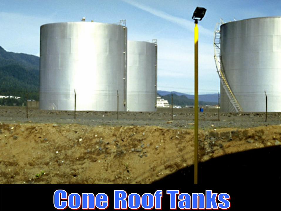
CONE ROOF TANKS (CR)
FLOATING ROOF TANKS
DOME ROOF TANK
IFR EFR

(a) Advantage of Floating Roof Tanks

MINIMIZING VAPOR SPACE: (a) ELIMINATES FILLING LOSS
CONE ROOF TANKS
FLOATING ROOF TANKS

MINIMIZING VAPOR SPACE: (b) REDUCES BREATHING LOSS
FLOATING ROOF TANK
CONE ROOF TANKS

MINIMIZING VAPOR SPACE: (c) PROVIDES EFFECTIVE FIRE PROTECTION AND LIGHTING SAFETY, IT ALSO INHIBITS ROOF AND
SHELL CORROSION
FLOATING ROOF TANKS
CONE ROOF TANKS

(b) Type of Floating RoofThere are a variety of deck options that may be exercised depending on the service conditions of the stored product.
• Single Deck Pan Type• Single Deck pontoon Type• Double Deck
Selection of a specific type of roof and tank depends on the intended service conditions, such as the petroleum liquid being stored, its vapor pressure and corrosive nature, and the anticipated weather and loading conditions.
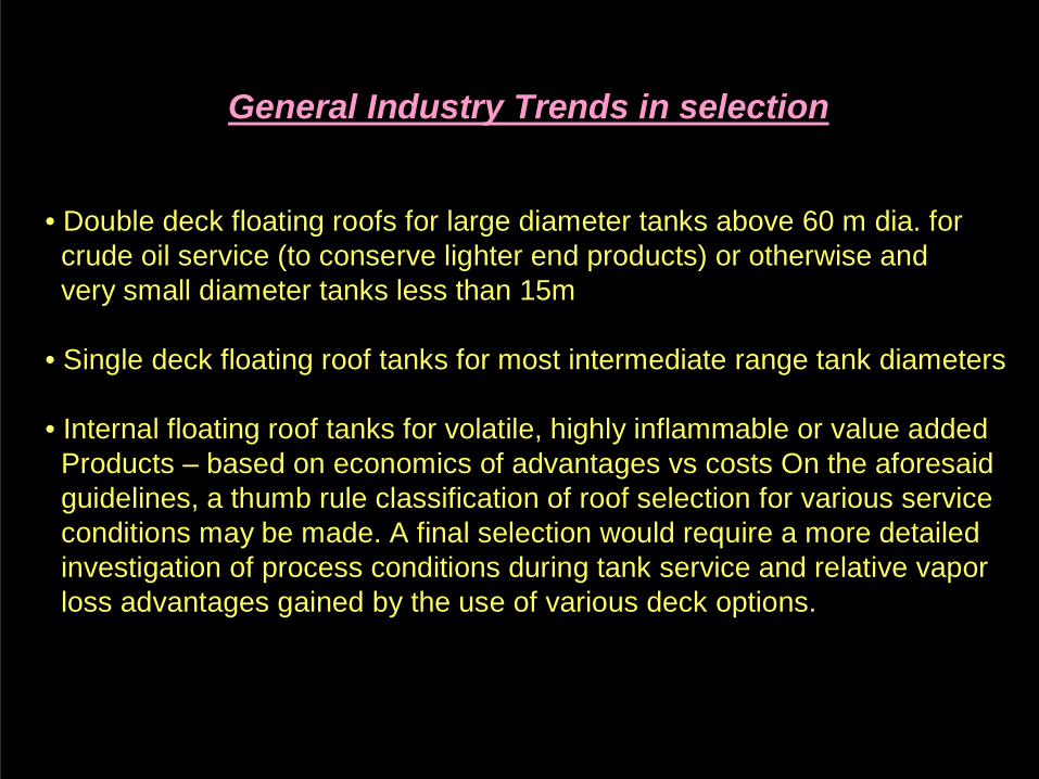
General Industry Trends in selection
• Double deck floating roofs for large diameter tanks above 60 m dia. forcrude oil service (to conserve lighter end products) or otherwise andvery small diameter tanks less than 15m
• Single deck floating roof tanks for most intermediate range tank diameters
• Internal floating roof tanks for volatile, highly inflammable or value addedProducts – based on economics of advantages vs costs On the aforesaidguidelines, a thumb rule classification of roof selection for various serviceconditions may be made. A final selection would require a more detailedinvestigation of process conditions during tank service and relative vaporloss advantages gained by the use of various deck options.

• Available in standard sizes from 15 – 91.5 m diameter
• Provides a cost effective solution, compared to the double deck, except inthe larger and very small sizes
• Greater water carrying capacity while afloat
• Prone to weldseam fatigue cracking from extended exposure to high windconditions
• Sufficient pontoon volume to keep deck afloat with any two pontooncompartments punctured
• Pontoon area varies from 35% on small diameter roofs to 20% on largediameter roofs
• Pontoon underside slopes upward toward centre of roof to hold temperaturegenerated condensible vapors
SINGLE DECK (PONTOON TYPE) EXTERNAL FLOATING ROOF TANKS

SINGLE DECK EXTERNAL FLOATING ROOF TANKS (EFR)

Shell
Rim
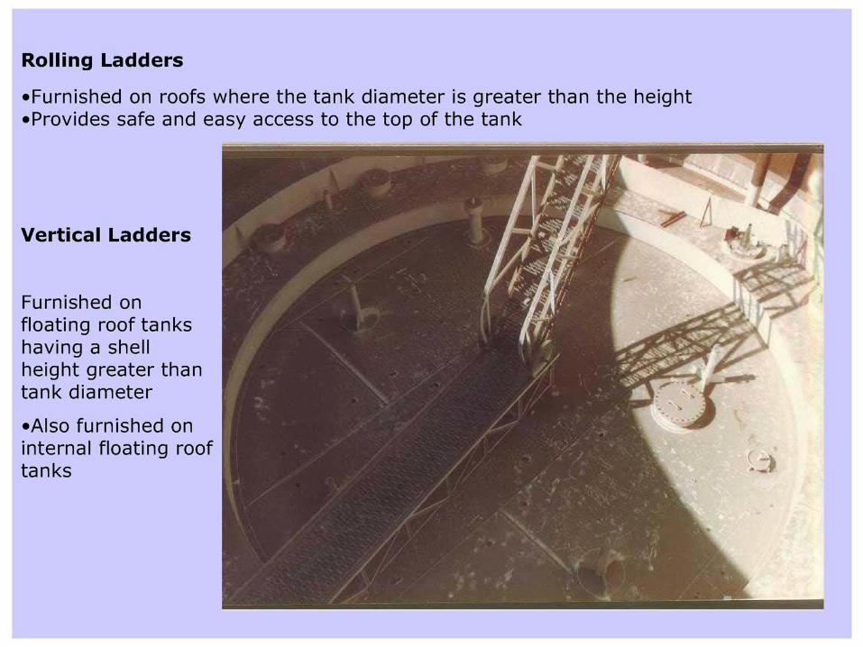
Roling ladder
(typ)
Deck Plate
Single Deck Pontoon Type Floating Roof Tank
Pontoon
Curb Angle

• Available in standard sizes from 9 – 122 m diameter
• Most efficient solution, double deck provides good insulation over entireliquid surface, most stable and maintenance free option for larger sizes
• Limited water carrying capacity while afloat, water allowed to passthrough deck
• Reduces impact of high winds on product, stable performance of deck undersuch conditions
• Emergency drains provided to accommodate 10” of rainfall in 24 hours
• Roof designed to float directly on product, and stay afloat with any twocompartments punctured. Deck flexibility allows temperature generatedcondensible vapor to be contained under center of deck
DOUBLE DECK EXTERNAL FLOATING ROOF TANKS

DOUBLE DECK EXTERNAL FLOATING ROOF TANKS (FR)

• Provides additional protection against wind and rain
• Combines the all-weather performance of a cone roof tank with theevaporation saving and fire protection qualities of a floating roof tank
• Maximum protection against exposure or rim fires
• Floating roof simultaneously combats corrosion and product deterioration
• No drainage system required – this eliminates maintenance of this item andfloating roof may be operated to lower levels
• In lieu of pan type construction, special pontoon type decks can be providedfor more positive floatation and increased stability.
• Shell/Roof vents provided for venting air-vapor mixture between the floatingdeck and fixed roof during product pump in
DOUBLE DECK INTERNAL FLOATING ROOF TANKS (IFR)
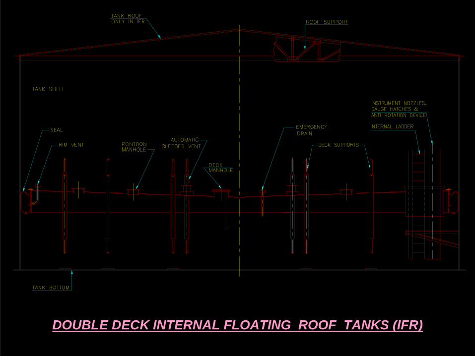
DOUBLE DECK INTERNAL FLOATING ROOF TANKS (IFR)

(c) Components of Floating RoofRim Seals
• All floating roof tanks have an annular space between tank shell andfloating Roof outer Rim.
• Rim Seals are used to control evaporative losses in the Rim seal area.• Effective rim seal systems close the rim space, accommodateirregularities between the floating roof and tank shell, and help to centerthe Roof.
(a) Foam or Resilient Filled Seal - (Liquid or Vapor Mounted)(b) Mechanical Shoe Seal
Liquid-Mouted Rim Seal
Means Rim Seal Mounted in a position resulting in the bottom of the seal being normally in contact with the stored product surface.
Vapor-Mouted Rim Seal
Means Rim Seal Mounted in a position resulting in the bottom of the seal being normally does not contact with the stored product surface.

(b) MECHANICAL SHOE(a) RESILIENT-FILLED (VAPOR MOUNTED)
(a) FOAM-FILLED SEAL (VAPOR MOUNTED)

(EXAMPLE) PARTS OF FOAM-FILLED SEAL (LIQUID MOUNTED)
DETAIL OF FOAM SEAL (OCTAGONAL)POLYURETHANE
POLYURETHANE FABRIC OR NEOPRANE


Roof Drains
• Permit Removal of rainwater from the top of Deck (FR)
(1) Closed type
(a) Swivel / Pivot Jointed Roof Drain(b) Flexible Hose Roof Drain
(2) Open Type
(a) Flush Drain(b) Overflow Drains
(Vapor Loss / Only for Double Decks)

PIPE DRAIN WITH SWING/PIVOT JOINTS

FLEXIBLE HOSE DRAIN

OPEN DRAIN
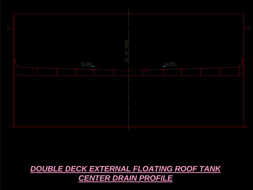
DOUBLE DECK EXTERNAL FLOATING ROOF TANKCENTER DRAIN PROFILE

DOUBLE DECK EXTERNAL FLOATING ROOF TANKREVERSE SLOPE PROFILE
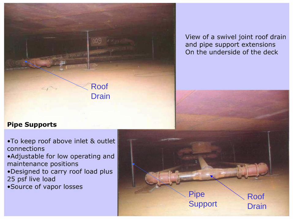
Pipe Support
Roof Drain
Roof Drain

EMERGENCY DRAINS
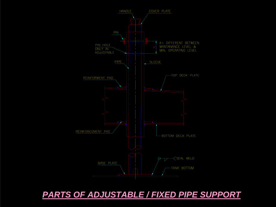
PARTS OF ADJUSTABLE / FIXED PIPE SUPPORT
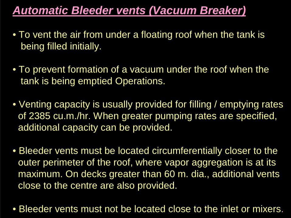
Automatic Bleeder vents (Vacuum Breaker)
• To vent the air from under a floating roof when the tank isbeing filled initially.
• To prevent formation of a vacuum under the roof when thetank is being emptied Operations.
• Venting capacity is usually provided for filling / emptying ratesof 2385 cu.m./hr. When greater pumping rates are specified,additional capacity can be provided.
• Bleeder vents must be located circumferentially closer to theouter perimeter of the roof, where vapor aggregation is at itsmaximum. On decks greater than 60 m. dia., additional ventsclose to the centre are also provided.
• Bleeder vents must not be located close to the inlet or mixers.

BLEEDER VENT
@ TANK FILLING
BLEEDER VENT
@ TANK EMPTYING
BLEEDER VENT
@ ROOF FLOATING

PARTS OF AUTOMATIC BLEEDER VENT

WORKING OF RIM VENT

PARTS OF RIM VENT


DECK MANWAY
• Deck manway is use to enter the tank bottom from top of deckby using internal ladder and also use as vent.during maintanance when tank is empty.
PONTOON MANWAY
• Pontoon Manway is use during hydrotest of pontoon.Water is inlet from pontoon manway.
• Generally size of Pontoon Manway is 20” NB.• Each compartment one & for big tank two required.• Pontoon manway is use to excess in pontoon for welding of
radial & circumferencial bulkhead to bottom deck also.

PARTS OF DECK MANWAY PARTS OF PONTOON MANWAY
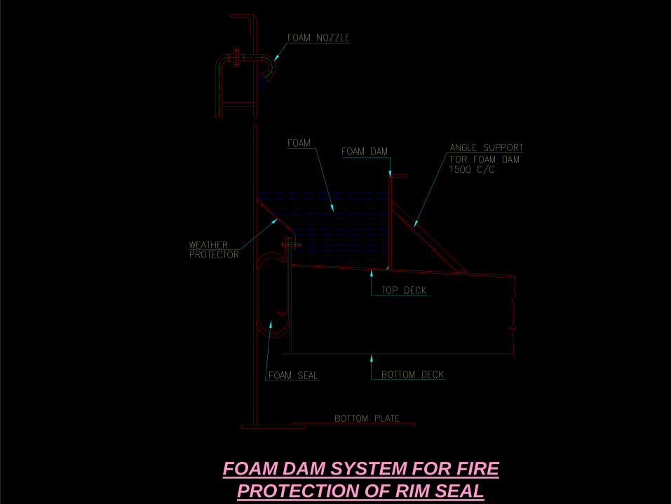
FOAM DAM SYSTEM FOR FIRE PROTECTION OF RIM SEAL

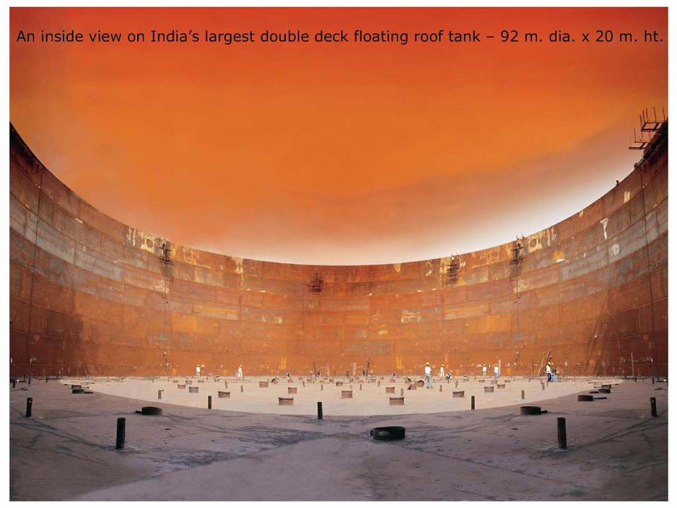
An Example of Deck Layout of Floating Roof Tank Size is
92m ID x 20M HT.EFR Tank for
Crude Oil Storage


(d) Design Elements
• Design Data• Material Selection• Shell Design• Bottom and Annular Design• Roof design ( For IFR)• Siesmic Analysis • Wind Loading Analysis
• Stiffening Design• Anchorage Design• Roof Structure Design (For IFR)• Deck Buoyancy Calculations• Floating Roof Support Design• Floating Roof Drain Design (For EFR)

Codes & Standards
• API 650 ‘Welded Steel Tanks for Oil Storage’ – most widely accepted
• Codes designed and constructed to the standard provide the uniformity,economy and safety for widespread use in the industry
• Wide range of material selection – Low strength steels may be used upto38mm and high strength steels upto 44mm
• Variable point method allows more sophisticated analysis of stresses forimproved use of steel on large tanks
• Appendix E – Siesmic Design – Recommended Minimum BasicRequirements
• Appendix C – External Floating Roof Design Requirements• Appendix H – Internal Floating Roof Design Requirements
• The British, Indian and other Standards are also available for tank designwhere specified

(e) Testing
• Vacuum Box testing of bottom and roof joints• DP / MP of shell to bottom joints• Plate Fabricated Neck - By Full Radiography • Annular to Shell - by Spot / Random Ultrasonic Testing• Tank shell - By filling water• All nozzle to Shell - MPT• Floating roof - By Floatation• Pontoon Bulkhead & Deck - By Vacuum Box / Oil-Chalk Test
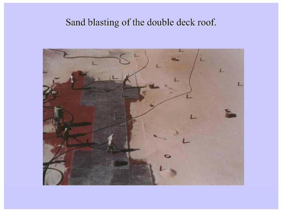
(f) Painting & Coating• Outside surface coated to protect tank from corrosion and rusting caused
by climatic conditions.• Color / Type selected to minimize vapor losses.• For corrosive service, special interior paints such as epoxy, rubber etc.
may be applied in lieu of a corrosion allowance or use of high cost materials.• Any tank surface in touch with liquid is usually left unpainted. This would
include deck underside and tank shell inside except crude oil service.• For crude oil service, inside of tank bottom and first few feet of tank
shell are coated with a special epoxy to provide for the surfaces.


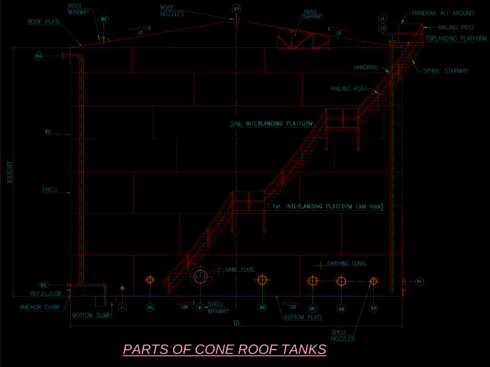
PARTS OF CONE ROOF TANKS

Lifting the Roof/Shell section of the tank.

The Roof and Top shell Section is Fit and being tacked from the Inside.

Dome Roof Knuckle Profile
Looking down on Knuckle

From,
Ketan M Suthar (FEG-Baroda)