t15 series switches - psd api
TRANSCRIPT

AECTB5E 202110Panasonic Corporation 2021
FEATURESRocker and push-button switches included in product lineupSealed type available for use in different environmentsRubber cap also available in silicon type for excellent weather resistance
* These switches are only for Industrial use. Do not use any other applications. (ex. home use)
Snap Switches Capable of 15 A SwitchingT-15 Series SwitchesFor operation: Snap Switches
29
17.7
15.8
(Unit: mm)
TogglePushbutton
Rocker
Squarehole
ASSORTMENT
Protection gradeNumber of pole
Shape of terminal
Operation shape
Standard type
Sealed type Number of pole Shape of terminal
Panel- sealed type
Terminal- sealed type
Wire leads type
1P 2P 3P 4P Solder terminal
Screw terminal
.250Quick-
connect terminal
Wire lead
Toggle type Available Available Available Available Available Available Available*1 Available*1 Available Available Available*1 Available*2
Rocker type Available Available Available Available Available Available - - Available Available - Available*2
Push-button type Available Available - - Available Available - - Available Available - -
Notes: *1: Only standard type (exclude sealed type) *2: Only wire leads type
industrial.panasonic.com/ac/e/2021.10 ー 1 ー

T-15 Series Switches (WD1, WDR1, WDB1)
Panasonic Corporation Electromechanical Control Business Divisionindustrial.panasonic.com/ac/e/ AECTB5E 202110Panasonic Corporation 2021
ORDERING INFORMATION (PART NO.)
WD 1
Number of pole and operation0: 1-pole, single throw1: 1-pole, double throw2: 2-pole, single throw3: 2-pole, double throw4: 3-pole, single throw5: 3-pole, double throw6: 4-pole, single throw7: 4-pole, double throw
Rating and Terminal0: 15 A 250 Quick-connect terminal1: 15 A Solder terminal2: 15 A Screw terminal
Kind of operation1: ON-OFF、ON-ON2: ON-OFF-ON3: ON-〈ON〉4: 〈ON〉-OFF-〈ON〉5: ON-OFF-〈ON〉〈 〉Momentary position
F
F: Cadmium-free product
WD 1 F
F: Cadmium-free productNumber of pole and operation0: 1-pole, single throw1: 1-pole, double throw2: 2-pole, single throw3: 2-pole, double throw
Rating and Terminal1: 15 A Solder terminal2: 15 A Screw terminal
Kind of operation1: ON-OFF、ON-ON2: ON-OFF-ON3: ON-〈ON〉4: 〈ON〉-OFF-〈ON〉5: ON-OFF-〈ON〉〈 〉Momentary position
Protective structure80: Panel sealed type81: Terminal sealed type82: Wire leads sealed type
Toggle types
Toggle switch waterproof types
ー 2 ー

T-15 Series Switches (WD1, WDR1, WDB1)
Panasonic Corporation Electromechanical Control Business Divisionindustrial.panasonic.com/ac/e/ AECTB5E 202110Panasonic Corporation 2021
TYPES
Toggle types
Standard type1) Solder terminal and .250 Quick-connect terminal
Number of poles
Kind of operation< >: Momentary position
Solder terminal Products subject to the Electrical
Appliances and Material Safety Act
.250 Quick-connect terminal Products subject to the Electrical Appliances and
Material Safety ActType No. Part No. Type No. Part No.
1-pole
ON-OFF T115A-F WD1011F - T115A-AF WD1001F -ON-ON T115D-F WD1111F - T115D-AF WD1101F -
ON-OFF-ON T115E-F WD1112F - T115E-AF WD1102F -ON-<ON> T115F-F WD1113F - T115F-AF WD1103F -
<ON>-OFF-<ON> T115G-F WD1114F - T115G-AF WD1104F -ON-OFF-<ON> T115H-F WD1115F - T115H-AF WD1105F -
2-pole
ON-OFF T215K-F WD1211F - T215K-AF WD1201F -ON-ON T215N-F WD1311F - T215N-AF WD1301F -
ON-OFF-ON T215P-F WD1312F - T215P-AF WD1302F -ON-<ON> T215R-F WD1313F - T215R-AF WD1303F -
<ON>-OFF-<ON> T215S-F WD1314F - T215S-AF WD1304F -ON-OFF-<ON> T215T-F WD1315F - T215T-AF WD1305F -
3-poleON-OFF T315K-F WD1411F - T315K-AF WD1401F -ON-ON T315N-F WD1511F - T315N-AF WD1501F -
ON-OFF-ON T315P-F WD1512F - T315P-AF WD1502F -
4-poleON-OFF T415K-F WD1611F - T415K-AF WD1601F -ON-ON T415N-F WD1711F - T415N-AF WD1701F -
ON-OFF-ON T415P-F WD1712F - T415P-AF WD1702F -Note: Standard installation accessories are included with the product.
2) Screw terminal
Number of poles
Kind of operation< >: Momentary position
Screw terminal Products subject to the Electrical Appliances and
Material Safety ActType No. Part No.
1-pole
ON-OFF T115A-SF WD1021F AvailableON-ON T115D-SF WD1121F Available
ON-OFF-ON T115E-SF WD1122F AvailableON-<ON> T115F-SF WD1123F Available
<ON>-OFF-<ON> T115G-SF WD1124F AvailableON-OFF-<ON> T115H-SF WD1125F Available
2-pole
ON-OFF T215K-SF WD1221F AvailableON-ON T215N-SF WD1321F -
ON-OFF-ON T215P-SF WD1322F -ON-<ON> T215R-SF WD1323F -
<ON>-OFF-<ON> T215S-SF WD1324F -ON-OFF-<ON> T215T-SF WD1325F -
3-poleON-OFF T315K-SF WD1421F -ON-ON T315N-SF WD1521F -
ON-OFF-ON T315P-SF WD1522F -
4-poleON-OFF T415K-SF WD1621F -ON-ON T415N-SF WD1721F -
ON-OFF-ON T415P-SF WD1722F -Note: Standard installation accessories are included with the product.
ー 3 ー
T-15 Series Switches (WD1, WDR1, WDB1)
Panasonic Corporation Electromechanical Control Business Divisionindustrial.panasonic.com/ac/e/ AECTB5E 202110Panasonic Corporation 2021
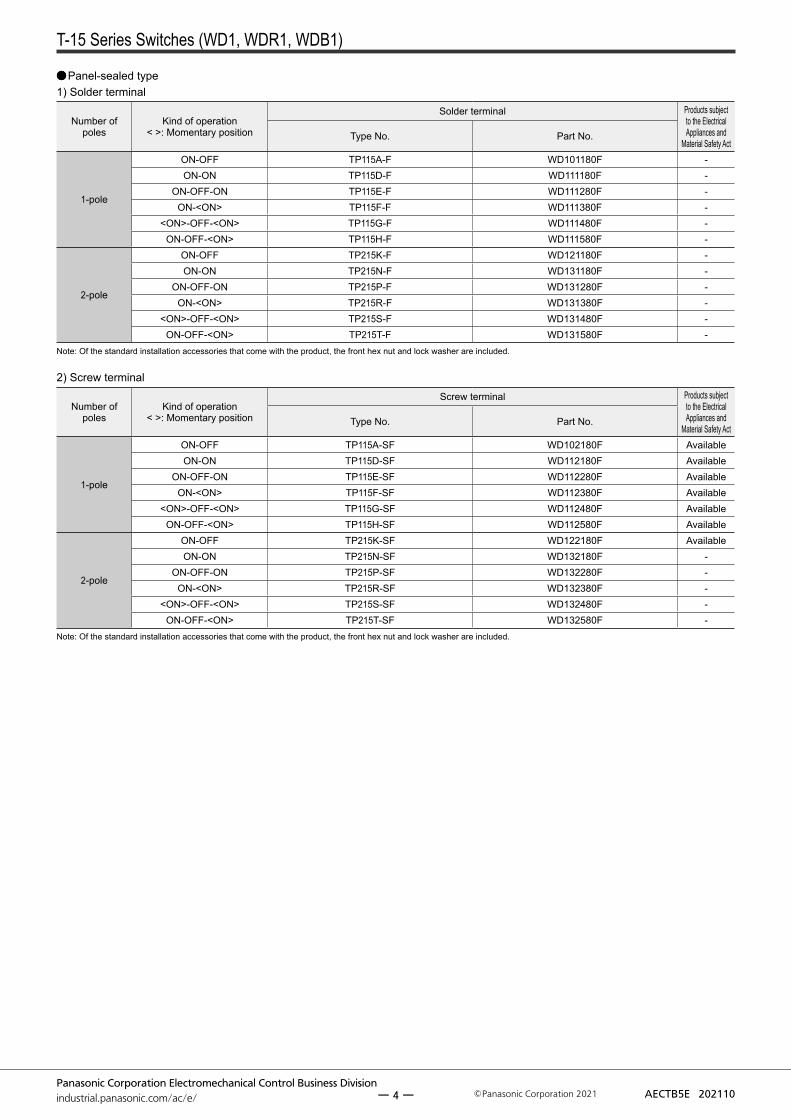
Panel-sealed type1) Solder terminal
Number of poles
Kind of operation< >: Momentary position
Solder terminal Products subject to the Electrical Appliances and
Material Safety ActType No. Part No.
1-pole
ON-OFF TP115A-F WD101180F -ON-ON TP115D-F WD111180F -
ON-OFF-ON TP115E-F WD111280F -ON-<ON> TP115F-F WD111380F -
<ON>-OFF-<ON> TP115G-F WD111480F -ON-OFF-<ON> TP115H-F WD111580F -
2-pole
ON-OFF TP215K-F WD121180F -ON-ON TP215N-F WD131180F -
ON-OFF-ON TP215P-F WD131280F -ON-<ON> TP215R-F WD131380F -
<ON>-OFF-<ON> TP215S-F WD131480F -ON-OFF-<ON> TP215T-F WD131580F -
Note: Of the standard installation accessories that come with the product, the front hex nut and lock washer are included.
2) Screw terminal
Number of poles
Kind of operation< >: Momentary position
Screw terminal Products subject to the Electrical Appliances and
Material Safety ActType No. Part No.
1-pole
ON-OFF TP115A-SF WD102180F AvailableON-ON TP115D-SF WD112180F Available
ON-OFF-ON TP115E-SF WD112280F AvailableON-<ON> TP115F-SF WD112380F Available
<ON>-OFF-<ON> TP115G-SF WD112480F AvailableON-OFF-<ON> TP115H-SF WD112580F Available
2-pole
ON-OFF TP215K-SF WD122180F AvailableON-ON TP215N-SF WD132180F -
ON-OFF-ON TP215P-SF WD132280F -ON-<ON> TP215R-SF WD132380F -
<ON>-OFF-<ON> TP215S-SF WD132480F -ON-OFF-<ON> TP215T-SF WD132580F -
Note: Of the standard installation accessories that come with the product, the front hex nut and lock washer are included.
ー 4 ー
T-15 Series Switches (WD1, WDR1, WDB1)
Panasonic Corporation Electromechanical Control Business Divisionindustrial.panasonic.com/ac/e/ AECTB5E 202110Panasonic Corporation 2021
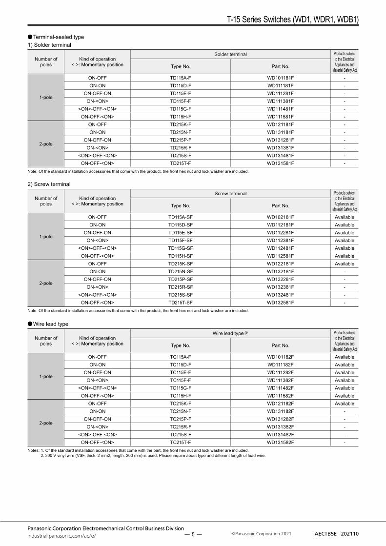
Terminal-sealed type1) Solder terminal
Number of poles
Kind of operation< >: Momentary position
Solder terminal Products subject to the Electrical Appliances and
Material Safety ActType No. Part No.
1-pole
ON-OFF TD115A-F WD101181F -ON-ON TD115D-F WD111181F -
ON-OFF-ON TD115E-F WD111281F -ON-<ON> TD115F-F WD111381F -
<ON>-OFF-<ON> TD115G-F WD111481F -ON-OFF-<ON> TD115H-F WD111581F -
2-pole
ON-OFF TD215K-F WD121181F -ON-ON TD215N-F WD131181F -
ON-OFF-ON TD215P-F WD131281F -ON-<ON> TD215R-F WD131381F -
<ON>-OFF-<ON> TD215S-F WD131481F -ON-OFF-<ON> TD215T-F WD131581F -
Note: Of the standard installation accessories that come with the product, the front hex nut and lock washer are included.
2) Screw terminal
Number of poles
Kind of operation< >: Momentary position
Screw terminal Products subject to the Electrical Appliances and
Material Safety ActType No. Part No.
1-pole
ON-OFF TD115A-SF WD102181F AvailableON-ON TD115D-SF WD112181F Available
ON-OFF-ON TD115E-SF WD112281F AvailableON-<ON> TD115F-SF WD112381F Available
<ON>-OFF-<ON> TD115G-SF WD112481F AvailableON-OFF-<ON> TD115H-SF WD112581F Available
2-pole
ON-OFF TD215K-SF WD122181F AvailableON-ON TD215N-SF WD132181F -
ON-OFF-ON TD215P-SF WD132281F -ON-<ON> TD215R-SF WD132381F -
<ON>-OFF-<ON> TD215S-SF WD132481F -ON-OFF-<ON> TD215T-SF WD132581F -
Note: Of the standard installation accessories that come with the product, the front hex nut and lock washer are included.
Wire lead type
Number of poles
Kind of operation< >: Momentary position
Wire lead typeき Products subject to the Electrical Appliances and
Material Safety ActType No. Part No.
1-pole
ON-OFF TC115A-F WD101182F AvailableON-ON TC115D-F WD111182F Available
ON-OFF-ON TC115E-F WD111282F AvailableON-<ON> TC115F-F WD111382F Available
<ON>-OFF-<ON> TC115G-F WD111482F AvailableON-OFF-<ON> TC115H-F WD111582F Available
2-pole
ON-OFF TC215K-F WD121182F AvailableON-ON TC215N-F WD131182F -
ON-OFF-ON TC215P-F WD131282F -ON-<ON> TC215R-F WD131382F -
<ON>-OFF-<ON> TC215S-F WD131482F -ON-OFF-<ON> TC215T-F WD131582F -
Notes: 1. Of the standard installation accessories that come with the part, the front hex nut and lock washer are included. 2. 300 V vinyl wire (VSF, thick: 2 mm2, length: 200 mm) is used. Please inquire about type and different length of lead wire.
ー 5 ー
T-15 Series Switches (WD1, WDR1, WDB1)
Panasonic Corporation Electromechanical Control Business Divisionindustrial.panasonic.com/ac/e/ AECTB5E 202110Panasonic Corporation 2021
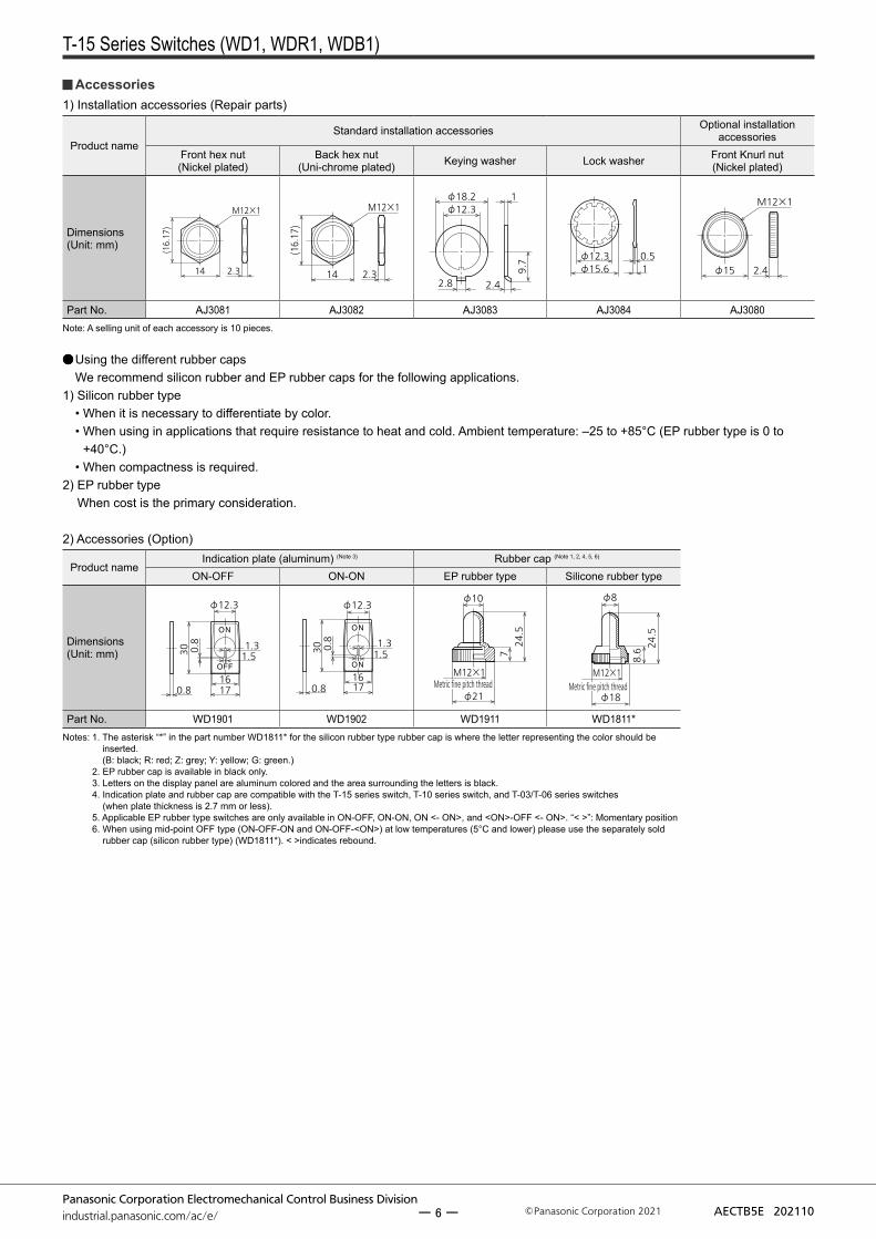
Accessories1) Installation accessories (Repair parts)
Product nameStandard installation accessories Optional installation
accessoriesFront hex nut(Nickel plated)
Back hex nut(Uni-chrome plated) Keying washer Lock washer Front Knurl nut
(Nickel plated)
Dimensions(Unit: mm)
14
(16.17)
2.3
M12×1
14
(16.17)
2.3
M12×1
2.8
φ18.2φ12.3
2.4
9.7
1
φ15.6φ12.3 0.5
1 φ15 2.4
M12×1
Part No. AJ3081 AJ3082 AJ3083 AJ3084 AJ3080Note: A selling unit of each accessory is 10 pieces.
Using the different rubber capsWe recommend silicon rubber and EP rubber caps for the following applications.
1) Silicon rubber type• When it is necessary to differentiate by color.• When using in applications that require resistance to heat and cold. Ambient temperature: –25 to +85°C (EP rubber type is 0 to
+40°C.)• When compactness is required.
2) EP rubber type When cost is the primary consideration.
2) Accessories (Option)
Product nameIndication plate (aluminum) (Note 3) Rubber cap (Note 1, 2, 4, 5, 6)
ON-OFF ON-ON EP rubber type Silicone rubber type
Dimensions(Unit: mm)
φ12.3
16
30
1.31.5
0.8
0.8 17
φ12.3
16
30
1.31.5
0.8
0.8 17
φ10
24.5
φ21
M12×1
7
Metric fine pitch thread
φ8
24.5
φ18
M12×1
8.6
Metric fine pitch thread
Part No. WD1901 WD1902 WD1911 WD1811*Notes: 1. The asterisk “*” in the part number WD1811* for the silicon rubber type rubber cap is where the letter representing the color should be
inserted. (B: black; R: red; Z: grey; Y: yellow; G: green.)
2. EP rubber cap is available in black only. 3. Letters on the display panel are aluminum colored and the area surrounding the letters is black. 4. Indication plate and rubber cap are compatible with the T-15 series switch, T-10 series switch, and T-03/T-06 series switches
(when plate thickness is 2.7 mm or less). 5. Applicable EP rubber type switches are only available in ON-OFF, ON-ON, ON <- ON>, and <ON>-OFF <- ON>. “< >”: Momentary position 6. When using mid-point OFF type (ON-OFF-ON and ON-OFF-<ON>) at low temperatures (5°C and lower) please use the separately sold
rubber cap (silicon rubber type) (WD1811*). < >indicates rebound.
ー 6 ー

T-15 Series Switches (WD1, WDR1, WDB1)
Panasonic Corporation Electromechanical Control Business Divisionindustrial.panasonic.com/ac/e/ AECTB5E 202110Panasonic Corporation 2021
WD R 1
Number of pole and operation0: 1-pole, single throw1: 1-pole, double throw2: 2-pole, single throw3: 2-pole, double throw
Rating and Terminal1: 15A Solder terminal2: 15A Screw terminal
Kind of operation1: ON-OFF、ON-ON2: ON-OFF-ON3: ON-〈ON〉4: 〈ON〉-OFF-〈ON〉5: ON-OFF-〈ON〉〈 〉Momentary position
Protective structureNo indication: Standard type
80: Panel sealed type81: Terminal sealed type82: Wire leads sealed type
Actuator colorB: black W: whiteR: red Z: dark grey
Actuato indicationWithout indication: No indication1: ON-OFF indication
Vertical directionONOFF
F
F: Cadmium-free product
ORDERING INFORMATION (PART NO.)
Rocker switches
TYPES
Rocker types
Standard type1) Solder terminal, without indication on actuator
Number of poles
Kind of operation< >: Momentary position
Solder terminal Products subject to the Electrical Appliances and
Material Safety ActType No. Part No.
1-pole
ON-OFF TR115A-*F WDR1011*F -ON-ON TR115D-*F WDR1111*F -
ON-OFF-ON TR115E-*F WDR1112*F -ON-<ON> TR115F-*F WDR1113*F -
<ON>-OFF-<ON> TR115G-*F WDR1114*F -ON-OFF-<ON> TR115H-*F WDR1115*F -
2-pole
ON-OFF TR215K-*F WDR1211*F -ON-ON TR215N-*F WDR1311*F -
ON-OFF-ON TR215P-*F WDR1312*F -ON-<ON> TR215R-*F WDR1313*F -
<ON>-OFF-<ON> TR215S-*F WDR1314*F -ON-OFF-<ON> TR215T-*F WDR1315*F -
Note: Please specify the actuator color by replacing the asterisk “*” in the part number with appropriate letter. (B: black; W: white; R: red; Z: dark grey)
2) Screw terminal, without indication on actuator
Number of poles
Kind of operation< >: Momentary position
Screw terminal Products subject to the Electrical Appliances and
Material Safety ActType No. Part No.
1-pole
ON-OFF TR115A-S*F WDR1021*F AvailableON-ON TR115D-S*F WDR1121*F Available
ON-OFF-ON TR115E-S*F WDR1122*F AvailableON-<ON> TR115F-S*F WDR1123*F Available
<ON>-OFF-<ON> TR115G-S*F WDR1124*F AvailableON-OFF-<ON> TR115H-S*F WDR1125*F Available
2-pole
ON-OFF TR215K-S*F WDR1221*F AvailableON-ON TR215N-S*F WDR1321*F -
ON-OFF-ON TR215P-S*F WDR1322*F -ON-<ON> TR215R-S*F WDR1323*F -
<ON>-OFF-<ON> TR215S-S*F WDR1324*F -ON-OFF-<ON> TR215T-S*F WDR1325*F -
Note: Please specify the actuator color by replacing the asterisk “*” in the part number with appropriate letter. (B: black; W: white; R: red; Z: dark grey)
ー 7 ー
T-15 Series Switches (WD1, WDR1, WDB1)
Panasonic Corporation Electromechanical Control Business Divisionindustrial.panasonic.com/ac/e/ AECTB5E 202110Panasonic Corporation 2021
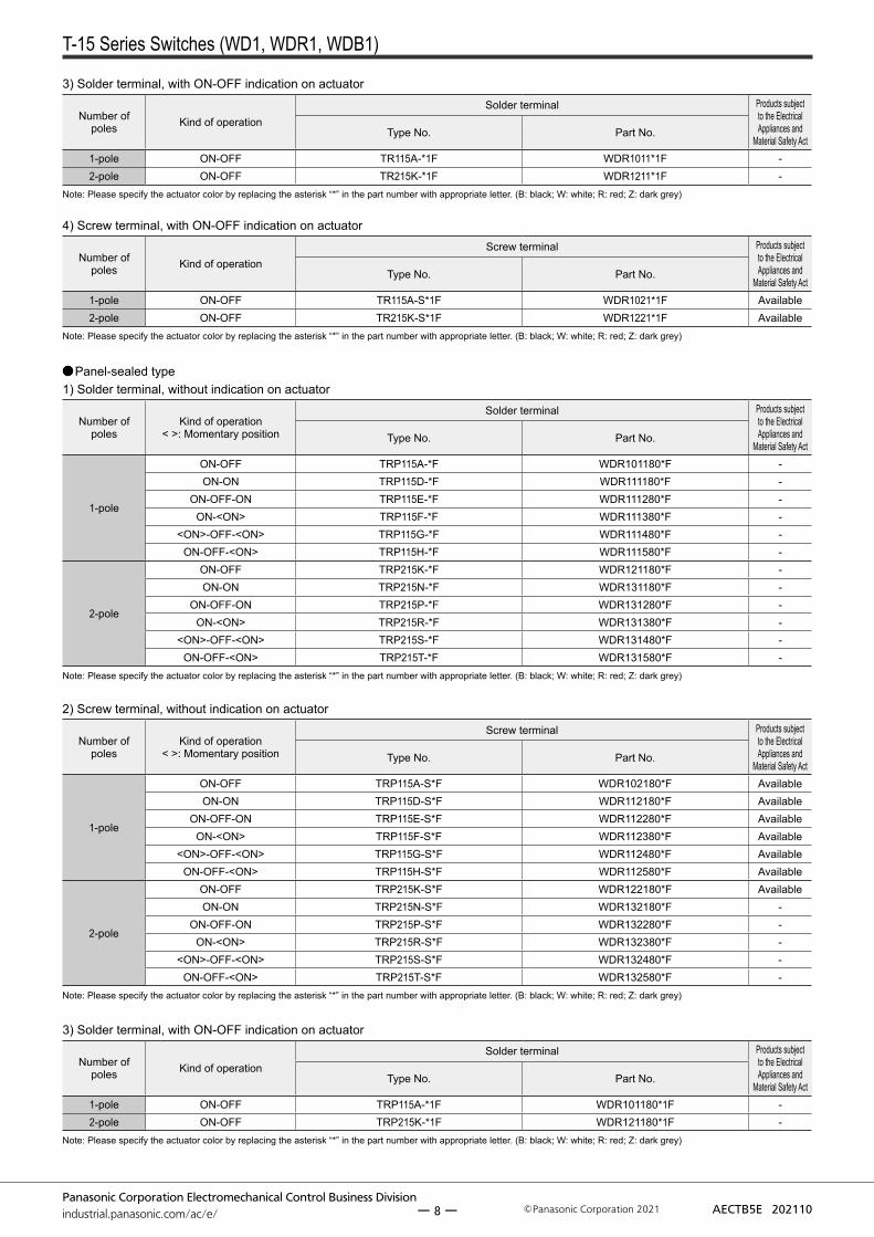
3) Solder terminal, with ON-OFF indication on actuator
Number of poles Kind of operation
Solder terminal Products subject to the Electrical Appliances and
Material Safety ActType No. Part No.
1-pole ON-OFF TR115A-*1F WDR1011*1F -2-pole ON-OFF TR215K-*1F WDR1211*1F -
Note: Please specify the actuator color by replacing the asterisk “*” in the part number with appropriate letter. (B: black; W: white; R: red; Z: dark grey)
4) Screw terminal, with ON-OFF indication on actuator
Number of poles Kind of operation
Screw terminal Products subject to the Electrical Appliances and
Material Safety ActType No. Part No.
1-pole ON-OFF TR115A-S*1F WDR1021*1F Available2-pole ON-OFF TR215K-S*1F WDR1221*1F Available
Note: Please specify the actuator color by replacing the asterisk “*” in the part number with appropriate letter. (B: black; W: white; R: red; Z: dark grey)
Panel-sealed type1) Solder terminal, without indication on actuator
Number of poles
Kind of operation< >: Momentary position
Solder terminal Products subject to the Electrical Appliances and
Material Safety ActType No. Part No.
1-pole
ON-OFF TRP115A-*F WDR101180*F -ON-ON TRP115D-*F WDR111180*F -
ON-OFF-ON TRP115E-*F WDR111280*F -ON-<ON> TRP115F-*F WDR111380*F -
<ON>-OFF-<ON> TRP115G-*F WDR111480*F -ON-OFF-<ON> TRP115H-*F WDR111580*F -
2-pole
ON-OFF TRP215K-*F WDR121180*F -ON-ON TRP215N-*F WDR131180*F -
ON-OFF-ON TRP215P-*F WDR131280*F -ON-<ON> TRP215R-*F WDR131380*F -
<ON>-OFF-<ON> TRP215S-*F WDR131480*F -ON-OFF-<ON> TRP215T-*F WDR131580*F -
Note: Please specify the actuator color by replacing the asterisk “*” in the part number with appropriate letter. (B: black; W: white; R: red; Z: dark grey)
2) Screw terminal, without indication on actuator
Number of poles
Kind of operation< >: Momentary position
Screw terminal Products subject to the Electrical Appliances and
Material Safety ActType No. Part No.
1-pole
ON-OFF TRP115A-S*F WDR102180*F AvailableON-ON TRP115D-S*F WDR112180*F Available
ON-OFF-ON TRP115E-S*F WDR112280*F AvailableON-<ON> TRP115F-S*F WDR112380*F Available
<ON>-OFF-<ON> TRP115G-S*F WDR112480*F AvailableON-OFF-<ON> TRP115H-S*F WDR112580*F Available
2-pole
ON-OFF TRP215K-S*F WDR122180*F AvailableON-ON TRP215N-S*F WDR132180*F -
ON-OFF-ON TRP215P-S*F WDR132280*F -ON-<ON> TRP215R-S*F WDR132380*F -
<ON>-OFF-<ON> TRP215S-S*F WDR132480*F -ON-OFF-<ON> TRP215T-S*F WDR132580*F -
Note: Please specify the actuator color by replacing the asterisk “*” in the part number with appropriate letter. (B: black; W: white; R: red; Z: dark grey)
3) Solder terminal, with ON-OFF indication on actuator
Number of poles Kind of operation
Solder terminal Products subject to the Electrical Appliances and
Material Safety ActType No. Part No.
1-pole ON-OFF TRP115A-*1F WDR101180*1F -2-pole ON-OFF TRP215K-*1F WDR121180*1F -
Note: Please specify the actuator color by replacing the asterisk “*” in the part number with appropriate letter. (B: black; W: white; R: red; Z: dark grey)
ー 8 ー

T-15 Series Switches (WD1, WDR1, WDB1)
Panasonic Corporation Electromechanical Control Business Divisionindustrial.panasonic.com/ac/e/ AECTB5E 202110Panasonic Corporation 2021
4) Screw terminal, with ON-OFF indication on actuator
Number of poles Kind of operation
Screw terminal Products subject to the Electrical Appliances and
Material Safety ActType No. Part No.
1-pole ON-OFF TRP115A-S*1F WDR102180*1F Available2-pole ON-OFF TRP215K-S*1F WDR122180*1F Available
Note: Please specify the actuator color by replacing the asterisk “*” in the part number with appropriate letter. (B: black; W: white; R: red; Z: dark grey)
Terminal-sealed type1) Solder terminal, without indication on actuator
Number of poles
Kind of operation< >: Momentary position
Solder terminal Products subject to the Electrical
Appliances and Material Safety Act
Type No. Part No.
1-pole
ON-OFF TRD115A-*F WDR101181*F -ON-ON TRD115D-*F WDR111181*F -
ON-OFF-ON TRD115E-*F WDR111281*F -ON-<ON> TRD115F-*F WDR111381*F -
<ON>-OFF-<ON> TRD115G-*F WDR111481*F -ON-OFF-<ON> TRD115H-*F WDR111581*F -
2-pole
ON-OFF TRD215K-*F WDR121181*F -ON-ON TRD215N-*F WDR131181*F -
ON-OFF-ON TRD215P-*F WDR131281*F -ON-<ON> TRD215R-*F WDR131381*F -
<ON>-OFF-<ON> TRD215S-*F WDR131481*F -ON-OFF-<ON> TRD215T-*F WDR131581*F -
Note: Please specify the actuator color by replacing the asterisk “*” in the part number with appropriate letter. (B: black; W: white; R: red; Z: dark grey)
2) Screw terminal, without indication on actuator
Number of poles
Kind of operation< >: Momentary position
Screw terminal Products subject to the Electrical
Appliances and Material Safety Act
Type No. Part No.
1-pole
ON-OFF TRD115A-S*F WDR102181*F AvailableON-ON TRD115D-S*F WDR112181*F Available
ON-OFF-ON TRD115E-S*F WDR112281*F AvailableON-<ON> TRD115F-S*F WDR112381*F Available
<ON>-OFF-<ON> TRD115G-S*F WDR112481*F AvailableON-OFF-<ON> TRD115H-S*F WDR112581*F Available
2-pole
ON-OFF TRD215K-S*F WDR122181*F AvailableON-ON TRD215N-S*F WDR132181*F -
ON-OFF-ON TRD215P-S*F WDR132281*F -ON-<ON> TRD215R-S*F WDR132381*F -
<ON>-OFF-<ON> TRD215S-S*F WDR132481*F -ON-OFF-<ON> TRD215T-S*F WDR132581*F -
Note: Please specify the actuator color by replacing the asterisk “*” in the part number with appropriate letter. (B: black; W: white; R: red; Z: dark grey)
3) Solder terminal, with ON-OFF indication on actuator
Number of poles Kind of operation
Solder terminal Products subject to the Electrical
Appliances and Material Safety Act
Type No. Part No.
1-pole ON-OFF TRD115A-*1F WDR101181*1F -2-pole ON-OFF TRD215K-*1F WDR121181*1F -
Note: Please specify the actuator color by replacing the asterisk “*” in the part number with appropriate letter. (B: black; W: white; R: red; Z: dark grey)
4) Screw terminal, with ON-OFF indication on actuator
Number of poles Kind of operation
Screw terminal Products subject to the Electrical
Appliances and Material Safety Act
Type No. Part No.
1-pole ON-OFF TRD115A-S*1F WDR102181*1F Available2-pole ON-OFF TRD215K-S*1F WDR122181*1F Available
Note: Please specify the actuator color by replacing the asterisk “*” in the part number with appropriate letter. (B: black; W: white; R: red; Z: dark grey)
ー 9 ー

T-15 Series Switches (WD1, WDR1, WDB1)
Panasonic Corporation Electromechanical Control Business Divisionindustrial.panasonic.com/ac/e/ AECTB5E 202110Panasonic Corporation 2021
Wire lead sealed type1) Without indication on actuator
Number of poles
Kind of operation< >: Momentary position
Wire lead type Products subject to the Electrical
Appliances and Material Safety Act
Type No. Part No.
1-pole
ON-OFF TRC115A-*F WDR101182*F AvailableON-ON TRC115D-*F WDR111182*F Available
ON-OFF-ON TRC115E-*F WDR111282*F AvailableON-<ON> TRC115F-*F WDR111382*F Available
<ON>-OFF-<ON> TRC115G-*F WDR111482*F AvailableON-OFF-<ON> TRC115H-*F WDR111582*F Available
2-pole
ON-OFF TRC215K-*F WDR121182*F AvailableON-ON TRC215N-*F WDR131182*F -
ON-OFF-ON TRC215P-*F WDR131282*F -ON-<ON> TRC215R-*F WDR131382*F -
<ON>-OFF-<ON> TRC215S-*F WDR131482*F -ON-OFF-<ON> TRC215T-*F WDR131582*F -
Notes: 1. Please specify the actuator color by replacing the asterisk “*” in the part number with appropriate letter. (B: black; W: white; R: red; Z: dark grey) 2. 300 V vinyl wire (VSF, thick: 2 mm2, length: 200 mm) is used. Please inquire about type and different length of lead wire.
2) With ON-OFF indication on actuator
Number of poles Kind of operation
Wire lead type Products subject to the Electrical
Appliances and Material Safety Act
Type No. Part No.
1-pole ON-OFF TRC115A-*1F WDR101182*1F Available2-pole ON-OFF TRC215K-*1F WDR121182*1F Available
Notes: 1. Please specify the actuator color by replacing the asterisk “*” in the part number with appropriate letter. (B: black; W: white; R: red; Z: dark grey) 2. 300 V vinyl wire (VSF, thick: 2 mm2, length: 200 mm) is used. Please inquire about type and different length of lead wire.
ー 10 ー

T-15 Series Switches (WD1, WDR1, WDB1)
Panasonic Corporation Electromechanical Control Business Divisionindustrial.panasonic.com/ac/e/ AECTB5E 202110Panasonic Corporation 2021
WD B 1
Number of pole and operation1: 1-pole, double throw3: 2-pole, double throw
Rating and Terminal1: 10A Solder terminal2: 10A Screw terminal
Kind of operation1: Alternate (ON-ON)3: Momentary (ON-〈ON〉)
Protective structureNo indication: Standard type 80 : Panel sealed type
F
F: Cadmium-free product
With colorcap installedSwitch body
Color cap(sold separately)
ORDERING INFORMATION (PART NO.)
Push-button switches
TYPES
Push-button product types
Standard type1) Solder terminal
Number of poles Kind of operation
Solder terminal Products subject to the Electrical
Appliances and Material Safety Act
Type No. Part No.
1-poleMomentary TB110F-F WDB1113F -Alternate TB115D-F WDB1111F -
2-poleMomentary TB210R-F WDB1313F -Alternate TB215N-F WDB1311F -
2) Screw terminal
Number of poles Kind of operation
Screw terminal Products subject to the Electrical
Appliances and Material Safety Act
Type No. Part No.
1-poleMomentary TB110F-SF WDB1123F AvailableAlternate TB115D-SF WDB1121F Available
2-poleMomentary TB210R-SF WDB1323F -Alternate TB215N-SF WDB1321F -
Notes: 1. Please use switch body with a color cap (sold separately). 2. Standard installation accessories are included with the product.
ー 11 ー

T-15 Series Switches (WD1, WDR1, WDB1)
Panasonic Corporation Electromechanical Control Business Divisionindustrial.panasonic.com/ac/e/ AECTB5E 202110Panasonic Corporation 2021
Panel-sealed type1) Solder terminal
Number of poles Kind of operation
Solder terminal Products subject to the Electrical
Appliances and Material Safety Act
Type No. Part No.
1-poleMomentary TBP110F-F WDB111380F -Alternate TBP115D-F WDB111180F -
2-poleMomentary TBP210R-F WDB131380F -Alternate TBP215N-F WDB131180F -
2) Screw terminal
Number of poles Kind of operation
Screw terminal Products subject to the Electrical
Appliances and Material Safety Act
Type No. Part No.
1-poleMomentary TBP110F-SF WDB112380F AvailableAlternate TBP115D-SF WDB112180F Available
2-poleMomentary TBP210R-SF WDB132380F -Alternate TBP215N-SF WDB132180F -
Notes: 1. Please use switch body with a color cap (sold separately). 2. Standard installation accessories are included with the product.
Installation accessories (Repair parts)
Product nameStandard installation accessories Optional installation
accessoriesFront hex nut(Nickel plated)
Back hex nut(Uni-chrome plated) Keying washer Lock washer Front Knurl nut
(Nickel plated)
Dimensions(Unit: mm)
14
(16.17)
2.3
M12×1
14
(16.17)
2.3
M12×1
2.8
φ18.2φ12.3
2.4
9.7
1
φ15.6φ12.3 0.5
1 φ15 2.4
M12×1
Part No. AJ3081 AJ3082 AJ3083 AJ3084 AJ3080Note: A selling unit of each accessory is 10 pieces.
Color cap for push-button (Option)
Product name Color cap(sold separately)
Dimensions(Unit: mm)
11.2
φ13.2
Part No. WDB1821*Note: Please specify the color cap color by replacing the asterisk “*” in the part number with appropriate letter
(B: black; W: white; R: red; Z: dark grey; H: light grey; Y: yellow; G: green; L: blue).
With colorcap installed
Switch bodyColor cap(sold separately)
ー 12 ー

T-15 Series Switches (WD1, WDR1, WDB1)
Panasonic Corporation Electromechanical Control Business Divisionindustrial.panasonic.com/ac/e/ AECTB5E 202110Panasonic Corporation 2021
CharacteristicsItem Specifications
Shape of actuator Toggle type Rocker type Push-button type
Mechanical expected life
1-pole and 2-pole: Min. 105
3-pole and 4-pole: Min. 8.5 × 10⁴
Min. 5 × 10⁴ (20 cpm) ON-OFF, ON-ON, ON-OFF-ON,Min. 3 × 10⁴ (20 cpm)ON-(ON), (ON)-OFF-(ON), ON-OFF-(ON)
Min. 3 × 10⁴ (20 cpm)
Electrical expected life (10 cpm)
Standard and panel-sealed types: Min. 3 × 10⁴
Terminal-sealed and wire leads types: Min. 1.5 × 10⁴
Standard type: Min. 3 × 10⁴ Panel-sealed, terminal-sealed and wire leads types: Min. 104
Min. 104
Dielectric strength 1500 Vrms for 1 min (at detection current: 10 mA)Insulation resistance Min. 100 MΩ (at 500 V DC measured by insulation resistive meter)
Contact resistance Initial, Max. 10 mΩ (By voltage drop at 1 A, 2 to 4 V DC)Wire leads type only: Initial, Max. 30 mΩ (By voltage drop at the end of the lead wire at 1 A, 2 to 4 V DC)
Actuator strength 112.7 N for 1 min (For operating direction)Vibration resistance 10 to 55 Hz at double amplitude of 1.5 mm (contact opening: Max. 1 ms)Terminal strength (static load) 24.5 N for 1 min
Ambient temperature –25 to +70°C (Not freezing below 0°C)Contact material AgZnO alloy
Tested condition: 250 V AC, Power factor: 0.6 and 10 cpm
Current (A)
2-pole and 1pole types
4-pole and 3-pole types10
9876543210
2 6 10 14 18 22 26 30
Num
ber o
f ope
ratio
ns (×
104 )
RATING
Contact rating1) Toggle type and Rocker type
Kind of load AC rating DC ratingResistive load 15 A 250 V 0.5 A 250 V, 0.9 A 125 V, 15 A 30 V
Inductive load 15 A 250 V (Power factor: 0.6)0.3 A 250 V (Time constant: 8 ms), 0.5 A 125 V (Time constant: 8 ms) 15 A 30 V (Time constant: 8 ms)
2) Push-button type (momentary)Kind of load AC rating DC rating
Resistive load 10 A 250 V 0.4 A 250 V, 0.8 A 125 V, 8 A 30 V
3) Push-button type (alternate)Kind of load AC rating DC rating
Resistive load 15 A 250 V 0.5 A 250 V, 0.9 A 125 V, 15 A 30 V
DATA
Electrical life, For toggle standard type
ー 13 ー

T-15 Series Switches (WD1, WDR1, WDB1)
Panasonic Corporation Electromechanical Control Business Divisionindustrial.panasonic.com/ac/e/ AECTB5E 202110Panasonic Corporation 2021
DIMENSIONS CAD The CAD data of the products with a “CAD” mark can be downloaded from our Website. Unit: mm
Toggle Type
Standard type1) Solder terminal
3 2 1
52
63
41
1-pole 2-pole
93
6
178
25
96
78
45
3 12
101112
3-pole 4-pole
General tolerance: ±0.5Note) ON-OFF type does not have terminal No. 2, 5, 8 and 11.
4
15.8
29 Hole for wireleads: φ2Length: 4
30°±4°
M12×1
Keyway
23.7
612
±0.
417
.5±
0.4
19.5
Hole for wireleads: φ2Length: 4
33
Keyway M12×1
276
12±
0.417
.5±
0.4
φ6.1
30°±8° 30°±4°
M12×1
Keyway
17.5
±0.
4
Hole for wireleads: φ2Length: 4
12±
0.427
6
φ6.1
33
28
30°±4°
36.5
Hole for wireleads: φ2Length: 4
33
M12×1
Keyway
17.5
±0.
412
±0.4
27
6
φ6.1φ6.1
123
6
5
413
1-pole 2-pole
85
96
74
23 1
9 78
36
1245
12 11 10
3-pole 4-pole
General tolerance: ±0.5Note) ON-OFF type does not have terminal No. 2, 5, 8 and 11.
17.5
±0.
4
M12×1
Keyway
30°±4°φ6.1
29
15.8
279.
317
.5±
0.4
12±
0.4
M12×1Keyway
30°±8°φ6.1
30.3
9.3
12±
0.4
33±0.4
19.5
30°±4° 30°±4°
M12×1
Keyway
33±0.4
30.3
17.5
±0.
412
±0.
49.
3
φ6.1
28
M12×1
Keyway
36.5
φ6.1
30.3
17.5
±0.
412
±0.
49.
3
33±0.4
CAD
2) Screw terminal (M3.5)
External dimensions
External dimensions
ー 14 ー

T-15 Series Switches (WD1, WDR1, WDB1)
Panasonic Corporation Electromechanical Control Business Divisionindustrial.panasonic.com/ac/e/ AECTB5E 202110Panasonic Corporation 2021
3 2 1
6
25
3
41
1-pole 2-pole
1
96
3
8 7
52
4
69
3
85
74
2 1101112
3-pole 4-pole
General tolerance: ±0.5Notes) 1: ON-OFF type does not have terminal No. 2, 5, 8 and 11. 2: There is no through-hole on .250 Quick-connect terminals.
φ6.1
30°±4°
M12×1Keyway
17.5
±0.
412
±0.
4
29
3-.250 Quickconnect terminal
9.3
27
15.8
M12×1Keyway
30°±8°
17.5
±0.
4
φ6.1
9.3
30.3
12±
0.4
6-.250 Quickconnect terminal
33
19.5
30°±8° 30°±8°
30.3
17.5
±0.
412
±0.
4
9.3
9-.250 Quickconnect terminal
M12×1Keyway
φ6.1
33
28
M12×1Keyway
12-.250 Quickconnect terminal
33
φ6.1
9.3
30.3
17.5
±0.
412
±0.
436
.5
3 2 1
136
52
4
1-pole 2-pole
General tolerance: ±0.5Note) ON-OFF type does not have terminal No. 2 and 5.
15.8
29
φ18
D cut
17.5
7.5
6
23.7
10
φ5.5
M12×1
30°±4°
φ5.5
φ18
D cut
30°±8°
26.9
6107.
5
17.5M12×1
19.5
33
3 2 1
6 4
3
52
1
1-pole 2-pole
General tolerance: ±0.5
30°±4°
φ18
D cut
φ18
D cut
9.3
27
M12×1
7.5
17.5
1015
.8
29
φ5.5 φ5.5
30°±8°
M12×1
17.5
7.5
10
9.3
30.2
19.5
33
3) .250 Quick-connect terminal
Panel-sealed type1) Solder terminal 2) Screw terminal (M3.5)
External dimensions
External dimensions External dimensions
ー 15 ー

T-15 Series Switches (WD1, WDR1, WDB1)
Panasonic Corporation Electromechanical Control Business Divisionindustrial.panasonic.com/ac/e/ AECTB5E 202110Panasonic Corporation 2021
1-pole 2-pole
63
52
41
3 2 1
General tolerance: ±0.5Note) ON-OFF type does not have terminal No. 2 and 5.
29
15.8
M12×1
23.7
5
10.37.5
17.5
φ5.5
φ18
D cut
30°±4°
17.5M12×1φ18
30°±8°
φ5.5
26.9
5
10.37.5
D cut
3319
.5
1-pole 2-pole
123
25
General tolerance: ±0.5
7.5
10.3
17.5
30°±4°
M12×1φ18
φ5.5
D cut
29
10.3
29
15.8
7.5
10.3
32.2
10.3
17.5M12×1
19.5
φ5.5
33
φ18
30°±8°
D cut
④
① ② ③ ① ⑥
③ ②
⑤
1-pole
General tolerance: ±0.5Note) 1: ON-OFF type does not have wire lead No. 2 and 5. 2: 300 V vinyl wire (VSF, thick: 2 mm2, length: 200 mm) is used.
2-pole
30.6
15.8
φ18
D cut
φ5.5
30°±4°
M12×1
200±
2017
.510
.333
.2
10±
47.
5
33
21.1
D cut
φ18
10±
4
200±
20
M12×1
10.37.5
36.4
17.5
φ5.5
30°±8°
Wire leads type
Terminal-sealed type1) Solder terminal
External dimensions External dimensions
2) Screw terminal (M3.5)
External dimensions
Color of wire leadsNo. Color
1 Brown2 Red3 Orange4 Yellow5 Green6 Blue
ー 16 ー
T-15 Series Switches (WD1, WDR1, WDB1)
Panasonic Corporation Electromechanical Control Business Divisionindustrial.panasonic.com/ac/e/ AECTB5E 202110Panasonic Corporation 2021
2 13
25
63
41
1-pole 2-pole
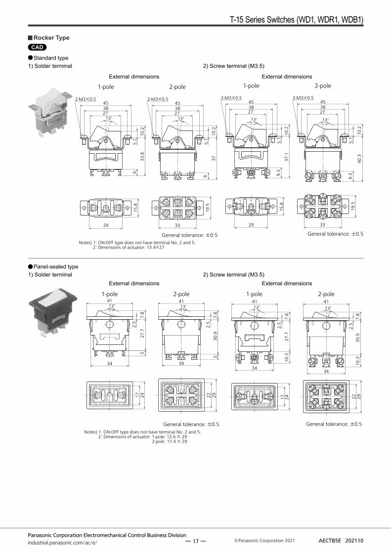
General tolerance: ±0.5Notes) 1: ON-OFF type does not have terminal No. 2 and 5. 2: Dimensions of actuator: 13.4×27
38
13°27
2-M3×0.545
65.
7
33.8
10.2
29
15.8
38
13° 27
2-M3×0.545
65.
7
3710
.2
33
19.5
CAD
123
1-pole 2-pole
General tolerance: ±0.5
6
52
4
3 1
2-M3×0.5
3827
45
13°
29
15.8
9.3
37.1
10.2
5.7
13°
5.7
10.2
3827
2-M3×0.545
9.3
40.3
33
19.5
3
6 4
2 1
52
3 1
1-pole 2-pole
General tolerance: ±0.5Notes) 1: ON-OFF type does not have terminal No. 2 and 5. 2: Dimensions of actuator: 1-pole: 12.6 × 29 2-pole: 17.4 × 29
13°41
34
5
2.5
27.7
7.8
17 24 2922
13°41
30.9
7.8
52.
5
34
13 2
52
1-pole 2-pole
General tolerance: ±0.5
10.3
2.5
27.7
7.8
4113°
34
2417 2922
13°41
34
10.3
2.5
30.9
7.8
Rocker Type
Standard type1) Solder terminal
Panel-sealed type1) Solder terminal
2) Screw terminal (M3.5)
External dimensions External dimensions
2) Screw terminal (M3.5)External dimensions External dimensions
ー 17 ー

T-15 Series Switches (WD1, WDR1, WDB1)
Panasonic Corporation Electromechanical Control Business Divisionindustrial.panasonic.com/ac/e/ AECTB5E 202110Panasonic Corporation 2021
6
52
3
41
23 1
1-pole 2-pole
General tolerance: ±0.5Notes) 1: ON-OFF type does not have terminal No. 2 and 5. 2: Dimensions of actuator: 1-pole: 12.6×29 2-pole: 17.4×29
2417 2922
13°41
345
27.7
2.5
7.8
13°41
530
.92.
57.
8
34
52
3 2 1
1-pole 2-pole
General tolerance: ±0.5
17 24
13°41
34
10.3
27.7
7.8
2.5
22 29
34
10.3
30.9
7.8
2.5
13°41
③ ② ① ⑥
③
⑤
②
④
①
1-pole 2-pole
General tolerance: ±0.5
Notes) 1: ON-OFF type does not have terminal No. 2 and 5. 2: Dimensions of actuator: 1-pole: 12.6×29, 2-pole: 17.4×29 3: 300 V vinyl wire (VSF, thick: 2 mm2, length: 200 mm) is used.
17 24
13°41
34
200±
2010
±4
42.2
2.5
7.8
13°
2922
34
10±
420
0±20
2.5
45.4
7.8
41
Color of wire leadsNo. Color
1 Brown2 Red3 Orange4 Yellow5 Green6 Blue
Terminal-sealed type1) Solder terminal 2) Screw terminal (M3.5)
External dimensions External dimensions
Wire leads type
External dimensions
ー 18 ー

T-15 Series Switches (WD1, WDR1, WDB1)
Panasonic Corporation Electromechanical Control Business Divisionindustrial.panasonic.com/ac/e/ AECTB5E 202110Panasonic Corporation 2021
3 2 1
6
5
4
2
3 1
1-pole 2-pole
General tolerance: ±0.5
29
15.8
33
19.5
Keyway
M12×1φ13.2
17.3
23.7
15.9
4.7
96
φ13.2
Keyway
M12×1
144.7
915
.926
.96
CAD
3 2 1
46
52
3 1
29 33
19.5
15.8
φ13.2
Keyway
M12×1
5.9 17
.1932
.314
6
M12×1
Keyway
φ13.21-pole 2-pole
General tolerance: ±0.5
632
.414
5.9
917
.1
123
6
52
4
3 1
1-pole 2-pole
General tolerance: ±0.5
29
15.8
9.3
9.3
33
19.5
3 2 1
6
5
4
2
3 1
1-pole 2-pole
General tolerance: ±0.5
29
15.8
33
19.5
D cut
9
17.7
15
.9
φ13.2
M12×1
23.7
64.3
7.
5 D cut
9
φ13.2
14.4
15.9
4.3
7.5
M12×1
26.9
6
3 2 1
46
52
3 1
1-pole 2-pole
General tolerance: ±0.5
29
15.8
33
19.5
6
14.4
15.9
4.37.
5
M12×1
32.3
D cut
9
φ13.2
D cut
φ13.2
9
14.4
15.9
4.37.
5
M12×1
632
.4
123
6
52
4
3 1
1-pole 2-pole
General tolerance: ±0.5
9.3
15.8
29
9.3
19.5
33
Push-button Type
Standard type• Solder terminal, Momentary • Solder terminal, Alternate • Screw terminal (M3.5)
Both momentary and alternate types only differ in the left solder terminal type and the terminal type.
External dimensions External dimensions
External dimensions
Panel-sealed type• Solder terminal, Momentary • Solder terminal, Alternate
External dimensions External dimensions
External dimensions
• Screw terminal (M3.5) Both momentary and alternate types only differ in the left solder terminal type and the terminal type.
ー 19 ー

T-15 Series Switches (WD1, WDR1, WDB1)
Panasonic Corporation Electromechanical Control Business Divisionindustrial.panasonic.com/ac/e/ AECTB5E 202110Panasonic Corporation 2021
Type Panel-sealed, Terminal-sealed and Wire leads types
Panel cutout(Unit: mm)
φ12.5
11.2
φ12.5
Panel thickness Max. 4 mm Max. 4 mm
(without keying washer)Note: For panel installations of standard type, be use to use the back hex nut.
MOUNTING DIMENSIONS
Toggle typeType Standard type
Panel cutout(Unit: mm)
φ12.5
9.2±0.1
φ3+0.2 0
φ12.5φ12.3
11.5
1.5
Panel thickness Max. 4.6 mm Max. 5.6 mm
(without keying washer)Max. 5.6 mm
(without keying washer)
Front hex nut
Keying washer
Lock washer
Back hex nut
Rocker typeType Standard type Panel-sealed, Terminal-sealed and Wire leads types
Panel cutout(Unit: mm)
38±0.3
2-φ3.5±0.1
14.5+0.3 0
28+0.3
0
1-pole 2-pole34
.2±
0.1
22.2±0.117.2±0.1
34.2
±0.
1 Max. R0.5 Max. R0.5
Panel thickness Max. 4.5 mm 1.2 to 3.2 mm
Push-button TypeType Standard type Panel-sealed type
Panel cutout(Unit: mm)
φ12.5
9.2±0.1
φ3+0.2 0
φ12.5φ12.3
11.5
1.5
φ12.5
11.2
φ12.5
Panel thickness
Momentary, 1-pole:Max. 10 mm
Momentary, 2-pole:Max. 6.5 mm
Alternate: Max. 6.5 mm
Momentary, 1-pole:Max. 10 mm Momentary,
2-pole: Max. 7.5 mmAlternate: Max. 7.5 mm(without keying washer)
Momentary, 1-pole:Max. 11 mm Momentary,
2-pole: Max. 7.5 mmAlternate: Max. 7.5 mm(without keying washer)
Max. 4 mm Max. 4 mm(without keying washer)
Note: For panel installations of standard type, be use to use the back hex nut.
ー 20 ー

T-15 Series Switches (WD1, WDR1, WDB1)
Panasonic Corporation Electromechanical Control Business Divisionindustrial.panasonic.com/ac/e/ AECTB5E 202110Panasonic Corporation 2021
TERMINAL CIRCUIT DIAGRAM
Toggle type and Rocker typeNumber of pole 1-pole 2-pole 3-pole 4-pole
Toggle type Available Available Available*3 Available*3
Rocker type Available Available - -
Terminal arrangement(As seen from terminal side)
Keyway
123
Keyway
456
123
123
456
789
Keyway Keyway
123
456
789
101112
Actu
ator
pos
ition
and
con
tact
term
inal
num
ber
Actuator shape Toggle type
Rocker type
ON-OFF
Keyway
RightPart No. 1-3 1-3, 4-6 1-3, 4-6, 7-9 1-3, 4-6,
7-9, 10-12
- - - - - -
Keyway
Left- - - -
ON-ONON<ON>
*1
Keyway
RightPart No. 2-3 2-3, 5-6 2-3, 5-6, 8-9 2-3, 5-6,
8-9, 11-12
- - - - - -
Keyway
Left*2 1-2 1-2, 4-5 1-2, 4-5, 7-8 1-2, 4-5,
7-8, 10-11
ON-OFF-ON<ON>-OFF-<ON>
ON-OFF-<ON>*1
Keyway
RightPart No. 2-3 2-3, 5-6 2-3, 5-6, 8-9 2-3, 5-6,
8-9, 11-12
Keyway
Center- - - -
Keyway
Left*2 1-2 1-2, 4-5 1-2, 4-5, 7-8 1-2, 4-5,
7-8, 10-11
RemarksON-OFF type doesnot have a terminal
No. 2.
ON-OFF type doesnot have terminal
No. 2 and 5.
ON-OFF type doesnot have terminal
No. 2, 5 and 8.
ON-OFF type doesnot have terminalNo. 2, 5, 8 and 11.
Notes: *1. For ON-<ON>, ON-OFF-<ON> type of toggle, if the lever turns to the keyway side, it takes momentary position. *2. For the rocker type, if the actuator turns to the left side in view of the side where a part number is marked, it takes momentary position. *3. Only standard type
Push-button TypeNumber of pole 1-pole 2-pole
Terminal arrangement(As seen from terminal side)
Keyway
123
Keyway
456
123
Push-button positionand contact terminal number
2-3 2-3, 5-6
Operated
1-2 1-2, 4-5
ー 21 ー

T-15 Series Switches (WD1, WDR1, WDB1)
Panasonic Corporation Electromechanical Control Business Divisionindustrial.panasonic.com/ac/e/ AECTB5E 202110Panasonic Corporation 2021
GUIDELINES FOR USAGE
Dustproof, waterproof, anticorrosive gas, and oil-proof designsThe panel-sealed type/terminal-sealed type/wire lead type switch has a protection level of IP67 or IP64 on the outer side of the mounting panel and a level of IP40, IP60, or IP67 on the inner side of the panel. For actual application, note the following points:1) Avoid immersion in water or oil during installation.2) Avoid immersion in water or oil during operation.3) Oils or gases impose varying degrees of impact on the
switch’s sealing performance depending on type or quantity.4) While the switch has a immersion and dust-protected
design, its sealing performance or operabillity may be adversely affected in an environment where in the switch's movable parts can be contaminated with dust, oil, or other foreign objects. For the toggle type, use of a rubber cap is recommended.
5) The standard toggle switch, when used with a rubber cap, provides a protection level of IP54. It should be used in an environment where it will not be subject to frequent water splashes.
6) As the sealing performance of the rocker type switch is affected by the panel processing accuracy or mounted panel thickness, check the switch under actual loading conditions. (While water or dust will not enter the switch’s internal structure, it may enter the panel.)
7) Do not operate the rocker type switch when water accumulates in the actuator.
Snap switch water resistance performancePanel front Panel interior
Toggle type
Rocker type
Push- button type
Toggle type
Rocker type
Push- button type
Standard type + Rubber cap IP54 – – IP40 – –
Panel-sealed type IP67 IP64 IP67 IP40 IP40 IP40
Terminal-sealed type IP67 IP64 – IP60 IP60 –
Wire leads type IP67 IP64 – IP67 IP67 –
Installation1) For the toggle and push-button type
a. When installing the standard type switch, be sure to use a hex nut.
b. For the panel-sealed, terminal-sealed and wire lead types, use a lock washer on the front side of the panel, and an O-ring on the back side of it.
c. Do not install the switch by holding and tightening it by hand.
2) For the rocker typea. In case the panel-sealed, terminal-sealed or wire leads
types are used in the condition where the water splash on, please in the case of vertical installation, please install the switches tilt more than 25° or in the case of horizontal installation, please install the switches tilt more than 50°. (90° recommended)
(Vertical installation) (Horizontal installation)
Mounting panel
Min. 25°
Min. 50°
b. In case water inside the switch case may freeze, please install the switch vertically to avoid the water remain inside the switch.
3) Rubber cap installationa. The washer should be used on the back side of the
panel.
3 to 3.5 mm
Washer
b. Enough screw pitch should be obtained being adjusted within 3 to 3.5mm.
c. After first installing the rubber cap, please tighten to 1.96 Nm or less with a hexagonal nut.
d. The mounting hole in the panel should preferably be provided with an anti-rotation projection.
Mounting hole
ー 22 ー

T-15 Series Switches (WD1, WDR1, WDB1)
Panasonic Corporation Electromechanical Control Business Divisionindustrial.panasonic.com/ac/e/ AECTB5E 202110Panasonic Corporation 2021
e. If the rubber cap is installed over the hex nut, the waterproof performance will be impaired although the dustproof performance will not be affected.
Hexagonal nut
SolderingPerform soldering in less than 3 seconds with maximum 350°C iron. Care should be taken not to apply force to the terminals during soldering. We recommend a soldering iron with temperature adjustment in order to prevent poor quality soldering.Please consult us if you intend to use a soldering iron of 60 W or higher.
Load type and ratings1) When the switch is loaded with a lamp, motor or capacitive
load, a surge current higher than the stationary current passes through the switch contacts. Measure the surge with the actual load and, if needed, take necessory action so that the surge will not exceed the switch’s rated current.
2) When the switch is loaded with an inductive load (relay, solenoid, buzzer, etc.), a contact failure may result from arc discharge caused by a counterelectromotive force. It is advisable that you use an adequate anti-spark circuit across the switch contacts.
Regarding Electrical Appliances and Material Safety Act1) Target products
For terminal shapes that are screw terminal type and that have wire leads, the models whose switch operation type is SPST, SPDT and DPST are targeted as "specified electrical appliances".Regarding some of the target Panasonic T-15 Series Switches, they have been inspected for conformity by a third-party accreditation organization and satisfy the standards. However, in the conformance testing, these models are restricted for use as embedded components and cannot be used for other applications such as household products.
2) Non-targeted productsIn the Electrical Appliances and Material Safety Act, switches of "special construction for embedding in devices" are non-targeted special electrical appliances and are not under obligation to undergo conformance inspection, but they must satisfy technical standards. The conditions for not being targeted for the Electrical Appliances and Material Safety Act are that 1) they must not be SPST, SPDT and DPST types and 2) they must have solder terminals, FASTON terminals or PCB terminals, however, because non-targeted products are also switches for embedding into devices, they cannot be used for other applications such as household products.
Others1) Do not apply an excessive static load exceeding 112.7 N
perpendicular to the direction of operation.2) Operate the switch actuator by hand.3) Take care not to drop the product as it may impair
performance.
ー 23 ー

T-15 Series Switches (WD1, WDR1, WDB1)
Panasonic Corporation Electromechanical Control Business Divisionindustrial.panasonic.com/ac/e/ AECTB5E 202110Panasonic Corporation 2021
Please refer to "the latest product specifications"when designing your product.•Requests to customers:https://industrial.panasonic.com/ac/e/salespolicies/
Dust-protected typeThis type of construction prevents dust that is large enough to have an effect on operation from getting inside the unit. This construction is stipulated by protective classes against solid matter in the IEC standards (IEC60529).The talcum powder used shall be able to pass through a squaremeshed sieve the nominal wire diameter of 75 μm. The amount of talcum powder to be used is 2 kg per cubic metre of the test chamber volume. The duration of the test is 8 hours. No damage observed after the test.
Immersion-protected typeThis type of construction prevents any harmful effects even after the device is left underwater at a depth of 1 m for 30 minutes. This construction is stipulated by protective classes against water in the IEC standards (IEC60529).
IEC’s IP CodesThe IEC (International Electrotechnical Commission) has defined the IP characteristic code that represents the levels of protection described in IEC standard (IEC60529).The two numbers that follow the IP code (the characteristics numbers) indicate the suitability of this protection for all environmental conditions.
IP1st characteristics number
2nd characteristics number
REFERENCE
Level of protection indicated by the 1st Characteristics number1st Characteristics
number Protection level (IEC60529/Solid matter)
0 No protection1 Protected against solid matter larger than 50 mm2 Protected against solid matter larger than 12 mm3 Protected against solid matter larger than 2.5 mm4 Protected against solid matter larger than 1.0 mm
5Dust-protected typePrevents dust that is large enough to have an effecton operation from getting inside the unit
6 Dust-resistant typePrevents dust from getting inside the unit
Level of protection indicated by the 2nd Characteristics number
JIS C09202nd
Characteristics number
Protection level(IEC60529/Liquid matter)
0 No protectionDroplet-
protected type I 1 Protected against water droplets that fall perpendicular to the unit
Droplet-protected type II 2
Protected against water droplets that fall from within 15° of perpendicular to the unit
Rain-protected type 3
Protected against water droplets that fall from within 60° of perpendicular to the unit
Splash-protected type 4 Protected against water that splashes
on the unit from any direction
Spray-protected type 5
Free from adverse effects even if sprayed directly with water from any direction
Water-resistant type 6 Protected against water sprayed directly
on the unit from any direction
Immersion- protected type 7
Water does not get inside of the unit when submerged in water according to the specified conditions
Underwater type 8 Unit can be used underwater
Note: Details of test conditions are the same as JIS C 0920. Please refer to them.
ー 24 ー

Panasonic Corporation Electromechanical Control Business Divisionindustrial.panasonic.com/ac/e/ Panasonic Corporation 2021 AECTB38E 202110
Technical Terminology & Cautions for Use (Operation Switches)
TECHNICAL TERMINOLOGY
Rated valuesValues indicating the characteristics and performance guarantee standards of the switches. The rated current and rated voltage, for instance, assume specific conditions.
Electrical lifeThe service life when the rated load is connected to the contact and switching operations are performed.
Mechanical lifeThe service life when operated at a preset operating frequency without passing electricity through the contacts.
Dielectric strengthThreshold limit value that a high voltage can be applied to a predetermined measuring location for one minute without causing damage to the insulation.
Insulation resistanceThis is the resistance value at the same place the dielectric strength is measured.
Contact resistanceThis indicates the electrical resistance at the contact part.Generally, this resistance includes the conductor resistance of the spring and terminal portions.
Vibration resistanceVibration range where a closed contact does not open for longer than a specified time due to vibrations during use of the snapaction switches.
Shock resistanceMax. shock value where a closed contact does not open for longer than a specified time due to shocks during use of the switches.
Allowable switching frequencyThis is the maximum switching frequency required to reach the end of mechanical life (or electrical life).
Temperature rise valueThis is the maximum temperature rise value that heats the terminal portion when the rated current is flowing through the contacts.
Actuator strengthWhen applying a static load for a certain period on the actuator in the operation direction, this is the maximum load it can withstand before the switch loses functionality.
Terminal strengthWhen applying a static load for a certain period (in all directions if not stipulated) on a terminal, this is the maximum load it can withstand before the terminal loses functionality (except when the terminal is deformed).
ー 25 ー

Panasonic Corporation Electromechanical Control Business Divisionindustrial.panasonic.com/ac/e/
Technical Terminology & Cautions for Use (Operation Switches)
Panasonic Corporation 2021 AECTB38E 202110
TYPES OF LOAD
Resistance loadResistance load is a power factor of 1 (cosφ = 1) where the load is only for the resistance portion. The displayed switch rating indicates the current capacity when using AC current.
DC loadDiffering from AC, since the direction of current is fixed for DC, the continuous arc time lengthens when the same voltage is applied.
Incandescent lamp loadSince an inrush current of 10 to 15 times the rated current flows for an instant when the switch is turned on for the lamp, adhesion of the contacts may occur. Therefore, please take into consideration this transient current when selecting a switch.
Induction loadSince arc generation due to reverse voltage can cause contact failure to occur when there is an induction load (in relays, solenoids and buzzers, etc.), we recommend you insert a suitable spark quenching circuit (see figure below).
Circuit example Notes
r c R
Switch contact(1) r = more than 10 Ω(2) In an AC circuit,
impedance of R is to be slightly smaller than impedance of r and c.
rc
R
Switch contactCan be used for both AC and DC circuits.r = RC: 0.1 μF
Rdiode
Switch contact
For DC circuits only.
ZNR Varistor
Switch contact
Induct
ion loa
d Can be used for both AC and DC circuits.
Motor loadContacts may adhere due to the starting current at the start of motor operation which is three to eight times the steady-state current. Although it differs depending on the motor, since a current flows that is several times that of the nominal current, please select a switch taking into consideration the values in the table below. To make the motor rotate in reverse, use an ON-OFF- ON switch and take measures to prevent a multiplier current (starting current + reverse current) from flowing.
Motor type Type Starting currentThree-phase
induction motor Squirrel-cage Approx. 5 to 8 times current listed on nameplate
Single-phase induction motor
Split-phase-start Approx. 6 times current listed on nameplate
Capacitor-start Approx. 4 to 5 times current listed on nameplate
Repulsion-start Approx. 3 times current listed on nameplate
A current that is approximately two times that of the starting current will flow when reverse rotation is caused during operation. Also, when using for a load that will cause transient phenomena such as when operating the motor in reverse rotation or switching the poles, an arc short (circuit short) may occur due to the time lag between poles when switching. Please be careful.
Wea
k Stro
ng
M M
MM
MM Powersupply
Powersupply
Example of 1-pole motor reverse rotation circuit Example of single-phase induction motor(capacitor) strong-weak switching circuit
Example of three-phase motorreverse rotation circuit
Good wiring Bad wiring Good wiring Good wiring
Good wiring Good wiring
Strong
Powersupply Power
supply
Powe
r supp
ly
Powersupply
Strong
StrongWeak Weak
Weak
Capacitor loadIn the case of mercury lamps, florescent lamps and the capacitor loads of capacitor circuits, since an extremely large inrush current flows when the switch is turned on, please measure that transient value with the actual load and then either use the product keeping within the range of the rated current or after verifying the actual load.
ー 26 ー

Panasonic Corporation Electromechanical Control Business Divisionindustrial.panasonic.com/ac/e/
Technical Terminology & Cautions for Use (Operation Switches)
Panasonic Corporation 2021 AECTB38E 202110
CAUTIONS FOR USE
Environment of use1) Please consult us when using under the following conditions:
• Environments where hydrogen sulfide or other corrosive gases are present.
• Environments where gasoline, thinner or other flammable, explosive gases are present.
• Dusty environments (for non-seal type snap action switches).• Use in environments not in the prescribed temperature or humidity
range.• Places with low air pressure.
2) Unless specified the product will not be constructed to withstand water, oil or explosions. Please inquire if you intend to use the product in special applications.
Usage, storage, and transport conditions1) During usage, storage, or transportation, avoid locations subject to
direct sunlight and maintain normal temperature, humidity, and pressure conditions.
2) The allowable specifications for environments suitable for usage, storage, and transportation are given below.(1) Temperature: The allowable temperature range differs for each
switch, so refer to the switch’s individual specifications.(2) Humidity: 5 to 85% R.H.(3) Pressure: 86 to 106 kPa
The humidity range varies with the temperature. Use within the range indicated in the graph below. (The allowable temperature depends on the switch.)
5
85
Humidity (% RH)
Avoid icingwhen used attemperatureslower than 0°C
Avoid con-densation when used at tem-peratures higher than 0°C
Allowable range
Ambient temperature (℃)0 85-40
Condensation will occur inside the switch if there is a sudden change in ambient temperature when used in an atmosphere of high temperature and high humidity. This is particularly likely to happen when being transported by ship, so please be careful of the atmosphere when shipping. Condensation is the phenomenon whereby steam condenses to cause water droplets that adhere to the switch when an atmosphere of high temperature and humidity rapidly changes from a high to low temperature or when the switch is quickly moved from a low humidity location to one of high temperature and humidity.Please be careful because condensation can cause adverse conditions such as deterioration of insulation, coil cutoff, and rust. Condensation or other moisture may freeze on the switch when the temperatures is lower than 0°C. This causes problems such as sticking of movable parts or operational time lags. The plastic becomes brittle if the switch is exposed to a low temperature, low humidity environment for long periods of time. Storage for extended periods of time (including transportation periods) at high temperatures or high humidity levels or in atmospheres with organic gases or sulfide gases may cause a sulfide film or oxide film to form on the surfaces of the contacts and/or it may interfere with the functions. Check out the atmosphere in which the units are to be stored and transported. In terms of the packing format used, make every effort to keep the effects of moisture, organic gases and sulfide gases to the absolute minimum.
Wiring1) When using a P/C board terminal switch as soldering terminals, use
thin lead wires and be sure to wind them on the terminals before soldering.
2) Cautions when soldering Perform soldering quickly in accordance with the specified conditions. Be careful not to let flux flow into the product. When no instruction is specified, use a soldering iron with a tip temperature of 350 C or lower and complete soldering within five seconds. Do not pull on the lead wires immediately after soldering. Wait some time before verifying.
Others1) Failure modes of switches include short-circuiting, opencircuiting
and temperature rises. If this switch is to be used in equipment where safety is a prime consideration, examine the possible effects of these failures on the equipment concerned, and ensure safety by providing protection circuits or protection devices. In terms of the systems involved, make provision for redundancy in the design and take steps to achieve safety design.
2) The ambient operating temperature (and humidity) range quoted is the range in which the switch can be operated on a continuous basis: it does not mean that using the switch within the rating guarantees the durability performance and environment withstanding performance of the switch. For details on the performance guarantee, check the specifications of each product concerned.
3) Even if 2-pole, 3-pole or 4-pole switches are used as singlepole switches in order to increase contact reliability, please keep the maximum current no higher than the rated value.
4) If there is the possibility of a short between poles, please use an in-phase circuit as shown below or provide a spare pole.
Load 1
Load 1
Load 1
Load 2
Load 2
Load 2
Bad example
Good example①
Good example②
Heteropolar circuit
In-phase circuit
Spare pole
5) Be careful not to drop the product as this may cause loss of functionality.
6) Do not apply an unreasonable vertical force against the direction of operation of the product.
7) Use your hand to operate the actuator. (Operation using a tool such as a screwdriver or hammer can cause breakdown.)
ー 27 ー

Please contact ..........
Electromechanical Control Business Division
industral.panasonic.com/ac/e/
Specifications are subject to change without notice.
1006, Oaza Kadoma, Kadoma-shi, Osaka 571-8506, Japan
©Panasonic Corporation 2021
AECTB5E 202110