triplex-k/quatrix-k backflow...
TRANSCRIPT

To ensure safe and proper usage, read the installation instructions and associated instructions for use carefully, provide them to end users, and keep them safely throughout the service life of the product.
Installation instructions
ACOIssued: 2017–03–07
0173.10.01 V 1.4-GB Translation of the original instructions
Assembly, installation and inspections
Triplex-K/Quatrix-K backflow stops
Triplex-K backflow stops and cleaning pipes (access points)
with shaft system for installation below ground
without shaft system, for installation in exposed pipelines
Quatrix-K automatic faecal backflow stops
with shaft system for installation below ground
without shaft system, for installation in exposed pipelines
The instructions for use for the Quatrix-K are included in the electrics pack!
2
Triplex-K/Quatrix-K backflow stopsIntroduction
Introduction
ACO Passavant GmbH "ACO" would like to thank you for your confidence. You have purchased a product that reflects best engineering practice and has undergone quality checks prior to delivery to ensure its proper condition.
Illustrations in these instructions are provided for basic understanding only and may differ from your version of the product and the installation situation.
Service, spare parts and accessories
For spare parts and accessories please see the "Product catalogue": http://www.aco.com
Please feel free to contact ACO Service if you require further information.
ACO Service Im Gewerbepark 11c
36457 Stadtlengsfeld
Germany
Tel.: + 49 36965 819-444 Fax: + 49 36965 819-367
For products purchased outside of Germany please visit local ACO Group website, http://www.aco.com
Guarantee
For information on warranties, please contact your local ACO stockist or local ACO Group member.
Warning messages and use of symbols
Certain information are marked in these instructions as follows:
NOTICE This signal word indicates the risk of damage to the product or environment
Tips and additional information to make your work easier
■ Bullets
Î Steps to be carried out in the specified order
References to further information contained in these instructions or in other documents

3
Triplex-K/Quatrix-K backflow stops
Table of contents
Table of contents
1 For your safety ................................................................................................. 4
1.1 Planning ..............................................................................................................4
1.2 Intended use .......................................................................................................5
1.3 Owner's responsibility ..........................................................................................6
1.4 Personnel qualification..........................................................................................6
1.5 Personal protective equipment ..............................................................................7
2 Product description ......................................................................................... 8
2.1 Product features ..................................................................................................8
2.2 Product identification..........................................................................................10
2.3 Dimensions and weights .....................................................................................12
3 Installation..................................................................................................... 16
3.1 Installation in exposed pipelines ..........................................................................16
3.2 Installation underground .....................................................................................18
4 Post-installation inspections .......................................................................... 24
4.1 Opening and closing the shaft system .................................................................24
4.2 Activating the emergency flap .............................................................................26
4.3 Triplex K-2: Tightness test ..................................................................................26
4.4 Quatrix-K: Tightness test ....................................................................................28
Annex: Handover procedure and documentation ..................................................... 30

4
For your safetyTriplex-K/Quatrix-K backflow stops
1 For your safety
Read the instructions before installing and using the backflow stop (cleaning pipe) to avoid personal injury and damage to property.
1.1 Planning
EN 12056-1 (5.5.2 Flooding within the building drainage system): "The design of a draining system shall minimize the risk of blockage with normal predictable usage of the system. The design of drainage systems shall avoid cross-flow from one sanitary appliance to another."
EN 12056-1 (5.5.3 Flooding prevention): "Wastewater collected or stored below flood level shall be discharged into the drainage system via an automatic wastewater lifting plant. In exceptional cases, anti-flooding valves may be permitted (see EN 12056-4)."
In the absence of any other specifications regarding the backflow level (e.g. in local byelaws governing public drainage systems), it is deemed to be the top of the road surface where the sewer connection is located.
NOTICE Backflow stops are designed for domestic use and may only be used if local building regulations and the following requirements according to EN 12056-4 are adhered to:
■ Gradient from the drainage line into the sewerage system. ■ Flooding does not present a health hazard or threaten valuable property. ■ There are only a small number of users and they have a WC available above the backflow level. ■ Use of the connected drainage points can be suspended in the event of a backflow.
Incorrect installation:
NOTICE Incorrect installation may lead to self-flooding and backflow if drainage points above the flood level are routed to a backflow stop.
Netzbetrieb
1x: Ton aus Test Betriebsverschluss1x: Zufahrt2x: Auffahrt2x: Grundeinstellungnach Störung
Dauerleuchten
Ausschalten1. Netzstecker ziehen2. Tasten (links/rechts)gleichzeitig5 Sekunden langdrücken.Einschalten3. Netzstecker ein-stecken umInitialisierungzu starten.
BlinkleuchtenAkkubetrieb
Rückstau
Betriebsverschluss zu
Motorstörung
Akkustörung
Betriebsverschluss fährt auf/zu
Backflow level

5
For your safetyTriplex-K/Quatrix-K backflow stops
Correct installation:
Only route drainage points below the flood level to a backflow stop. Connect downpipes for surface water downstream of the backflow stop in flow direction .
Netzbetrieb
1x: Ton aus Test Betriebsverschluss1x: Zufahrt2x: Auffahrt2x: Grundeinstellungnach Störung
Dauerleuchten
Ausschalten1. Netzstecker ziehen2. Tasten (links/rechts)gleichzeitig5 Sekunden langdrücken.Einschalten3. Netzstecker ein-stecken umInitialisierungzu starten.
BlinkleuchtenAkkubetrieb
Rückstau
Betriebsverschluss zu
Motorstörung
Akkustörung
Betriebsverschluss fährt auf/zu
1.2 Intended use
When wastewater drains overfill, e.g. following heavy rain, blockages or pumping station failures, wastewater can backflow and cause damage to buildings. Backflow stops are designed for domestic use and protect buildings against water damage. Cleaning pipes do not prevent backflow and are designed to be used for inspection and cleaning.
Cleaning pipes and backflow stops: ■ Versions with a shaft system are available for installation below ground. ■ Versions without a shaft system are available for installation in exposed pipelines. ■ Triplex K-0 (type 0), K-1 (type 1) backflow stops are tested to EN 13564-1 and approved for
rainwater recycling systems which have overflows connected to the storm water drainage line. ■ Triplex K-2 (type 2) backflow stops are tested to EN 13564-1 and approved for continuous
piping systems for wastewater free of faeces. ■ Quatrix-K automatic faecal backflow stops (type 3F) are tested to EN 13564-1 and approved
for wastewater both with and without faeces.
Hazardous substances may not be drained: ■ Solids, e.g. ashes, glass, sand, textiles, cardboard ■ Corrosive substances, e.g. acids, lyes, salts ■ Foaming substances, e.g. cleaning, dishwashing and washing agents in large quantities ■ Poisons, e.g. pesticides, pest control agents ■ Oil and grease
Backflow level

6
For your safetyTriplex-K/Quatrix-K backflow stops
1.3 Owner's responsibility
Functional reliability is only warranted if users perform monthly inspections and qualified technicians (for backflow stops type 3F) inspect and service the system every six months.
Please contact your local ACO stockist or Group member who will be pleased to recommend approved inspection and servicing technicians.
1.4 Personnel qualification
Skills required for installation, inspection and servicing: ■ Knowledge of buildings and building services ■ Assessment of wastewater technology applications ■ Excavating recesses (on-site building work) ■ Installation of drainage lines ■ Properly qualified personnel* for six-monthly inspections and servicing of backflow stops
(types 0, 1 and 2). ■ Properly qualified technicians** for six-monthly inspections and servicing of backflow stops
(type 3F).
*Definition according to DIN 1986-100: "Personnel of the operating company or of appointed third parties are regarded as "properly qualified" if, on account of their training, their knowledge and their experience gained through practical work, they can ensure that they can expertly carry out evaluations or tests in the specialised field in question. Properly qualified personnel can acquire the necessary expertise to perform certain inspections and function tests and/or checks, e.g. on separation systems, small sewage plants or backflow systems (excl. type 3 for wastewater containing faeces) in courses with subsequent on-site induction such as are offered, for example, by relevant manufacturers, trade associations, chambers of crafts or expert organisations operating in the field of separation technology."
**Definition according to DIN 1986-100: "Properly qualified technicians work for companies other than the operating company, or are experts or other institutions with documented proof of the necessary expertise for operating, servicing and inspecting separator units to the extent outlined above, and who have the technical equipment required to inspect separator units. In individual cases in larger companies, these inspections may also be performed by properly qualified technicians working for the operating company provided they are authorised to work independently and are not bound by instructions, and possess the same level of qualification and access to the necessary technical equipment."

7
For your safetyTriplex-K/Quatrix-K backflow stops
1.5 Personal protective equipment
Depending on the site requirements, personal protective equipment may be required, e.g. a helmet where there are low ceilings, protective footwear during the construction phase.

8
Product descriptionTriplex-K/Quatrix-K backflow stops
2 Product description
2.1 Product features
General features: ■ Large cleaning and maintenance openings ■ Connecting pipe in form of a spigot
Shaft system version: ■ Adjustable height and reversible top cover ■ Surface water-tight reversible cover - plastic finish or tile insert ■ Load class: K3 tested to EN 1253-1: Traffic-free surfaces with a maximum permitted load of
up to 300 kg.
Features of Triplex K cleaning pipe: ■ Suitable for rainwater, and wastewater with and without faeces ■ Can be upgraded to type 0, 1, 2 or type 3F backflow stop as per EN 13564-1
Features of Triplex K-0 single backflow stop: ■ Suitable for rainwater, type 0 as per EN 13564-1 ■ Automatic self-closing backflow flap ■ Can be upgraded to type 1, 2 or 3F as per EN 13564-1
Features of Triplex K-1 single backflow stop: ■ Suitable for rainwater, (type 1) as per EN 13564-1 ■ Automatic self-closing backflow flap combined with an emergency flap ■ Can be upgraded to type 2 or 3F as per EN 13564-1
Features of Triplex K-2 double backflow stop: ■ Suitable for wastewater free of faeces, (type 2) as per EN 13564-1 ■ Automatic self-closing backflow flap, and an automatic self-closing backflow flap combined
with an emergency flap ■ Can be upgraded to type 3F as per EN 13564-1

9
Product descriptionTriplex-K/Quatrix-K backflow stops
Features of the Quatrix-K automatic faecal backflow stop: ■ Suitable for wastewater both with and without faeces, (type 3F) as per EN 13564-1 ■ Electronic measuring system with a pressure sensor detects backflow automatically ■ Electronic monitoring of the drive function ■ Automatically closing operating flap (backflow flap) in the event of backflow, and one
emergency flap ■ Alarm sounds if backflow occurs ■ Battery operation in the event of a mains failure ■ Control unit is easy to operate ■ Isolated connection for notification systems (PC, telephone, alarm)

10
Product descriptionTriplex-K/Quatrix-K backflow stops
2.2 Product identification
The following table provides an overview of the Triplex backflow stops and cleaning pipes, and Quatrix-K automatic faecal backflow stops. The relevant type is shown on the lid of the casing (adhesive label).
NOTICE Check that none of the delivered items are damaged. Do not install any damaged parts; report them to the supplier, so that any claims can be processed.
Designation Art. no. Nominal width DN/OD
Mark product
Wit
ho
ut
shaf
t sy
stem
, fo
r in
stal
lati
on
in
exp
ose
d p
ipel
ines
Triplex K
Cleaning pipe (access point)
620352 110
620478 125
620353 160
Triplex K-0
Simple backflow stop
620356 110
620480 125
620357 160
Triplex K-1
Simple backflow stop
620360 110
620482 125
620361 160
Triplex K-2:
Double backflow stop
620364 110
620484 125
620365 160
Quatrix-K
Automatic faecal backflow stop
620368 110
620486 125
620369 160

11
Product descriptionTriplex-K/Quatrix-K backflow stops
Designation Art. no. Nominal width DN/OD
Mark product
Wit
h s
haf
t sy
stem
fo
r in
stal
lati
on
b
elo
w g
rou
nd
Triplex K
Cleaning pipe (access point)
620354 110
620479 125
620355 160
Triplex K-0
Simple backflow stop
620358 110
620481 125
620359 160
Triplex K-1
Simple backflow stop
620362 110
620483 125
620363 160
Triplex K-2:
Double backflow stop
620366 110
620485 125
620367 160
Quatrix-K
Automatic faecal backflow stop
620370 110
620487 125
620371 160
12
Product descriptionTriplex-K/Quatrix-K backflow stops
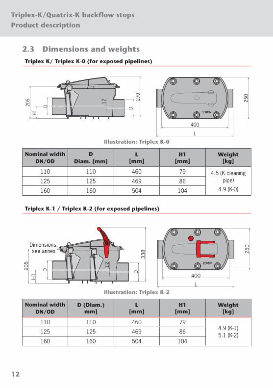
2.3 Dimensions and weightsTriplex K/ Triplex K-0 (for exposed pipelines)
D27
0
D205
H1
12
250
400
L
Illustration: Triplex K-0
Nominal width DN/OD
D Diam. [mm]
L [mm]
H1 [mm]
Weight [kg]
110 110 460 79 4.5 (K cleaning pipe)
4.9 (K-0)125 125 469 86
160 160 504 104
Triplex K-1 / Triplex K-2 (for exposed pipelines)
D338
D205
H1
12
250
400
L
Illustration: Triplex K-2
Nominal width DN/OD
D (Diam.) mm]
L [mm]
H1 [mm]
Weight [kg]
110 110 460 794.9 (K-1) 5.1 (K-2)
125 125 469 86
160 160 504 104
Dimensions, see annex

13
Product descriptionTriplex-K/Quatrix-K backflow stops
Triplex K/ Triplex K-0/ Triplex K-1/ Triplex K-2 (with shaft system)
D
H1
D
H2
H m
in. 4
05*
H m
ax. 5
12L
12
30
20
20
Ø676
360
Ø460
300
Illustration: Triplex K-2
Nominal width DN/OD
D (Diam.) [mm]
L [mm]
H1 [mm]
H2 [mm]
Space [mm]
Weight [kg]
110 110 460 79 217 560 x 710 11.9 (K) 12.3 (K-0) 12.3 (K-1) 12.7 (K-2)
125 125 469 86 210 560 x 730
160 160 504 104 192 560 x 820
*To upgrade to a Quatrix-K automatic faecal backflow stop, the minimum height requirement is 460 mm.
Dimension Hmin. = 405 – 426 mm can be achieved by reducing the length of the top section. (Hmax. = 512 mm).

14
Product descriptionTriplex-K/Quatrix-K backflow stops
Quatrix-K (for exposed pipelines)
D40
5
D205
H1
12
250
400
L
Illustration: Quatrix K
Nominal width DN/OD
D (Diam.) [mm]
L [mm]
H1 [mm]
Weight [kg]
110 110 460 79
9.1125 125 469 86
160 160 504 104
15
Product descriptionTriplex-K/Quatrix-K backflow stops
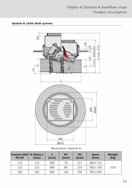
Quatrix-K (with shaft system)
D
H1
D
H2
H m
in. 405(X
X)*
H m
ax. 512
L
12
30
20
20
Ø676
360
Ø46
0
300
Illustration: Quatrix K
Nominal width DN/OD
D (Diam.) [mm]
L [mm]
H1 [mm]
H2 [mm]
Space [mm]
Weight [kg]
110 110 460 79 217 560 x 710
15.4125 125 469 86 210 560 x 730
160 160 504 104 192 560 x 820

16
InstallationTriplex-K/Quatrix-K backflow stops
3 Installation
This section describes the installation procedure with the help of two examples: Section 3.1 "Installation in exposed pipelines", and underground installation with shaft system, Section 3.2 "Installation underground".
The installation procedure for Triplex K cleaning pipes (access points) and Quatrix-K automatic faecal backflow stops is the same.
These installation instructions are a guideline only and may vary for each individual installation.
3.1 Installation in exposed pipelines
NOTICE Installation is only permissible in frost-protected pipelines (> 5 °C).
Observe the following during installation: ■ Use connectors (coupling sockets, adapters) when connecting to the pipeline. ■ The installation site must be easily accessible at all times for operation and servicing work.
NOTICE Pipeline slope to the drains must be 1.5 % to 2.0 %. The backflow stop has a built-in gradient, the outflow from the backflow stop is 12 mm lower than the inlet.
Î Make sure backflow stops are aligned vertically and horizontally, e.g. using a spirit level.
Î Connect the backflow stop in the direction of flow (the direction of flow is indicated by an arrow on the cover of the casing) to the pipeline, using the connectors.
1.5 % – 2.0 %

17
InstallationTriplex-K/Quatrix-K backflow stops
If not fixed to a wall:
Î Support backflow stop e.g. with a bracket.
When fixed to a wall:
Î Attach the pipe brackets to the wall above and below the backflow stop at least 150 mm apart. 15
0 mm
NOTICE Emergency flap must be open so that water can flow through.
Î Check the emergency flap Section 4.2 "Activating the emergency flap" (does not apply for Triplex K, K-0).

18
InstallationTriplex-K/Quatrix-K backflow stops
3.2 Installation underground
The following example describes the initial installation of a backflow stop with (optional) extension.
NOTICE Installation is only permissible in frost-protected ground (> 5 °C).
Observe the following during installation: ■ Use connectors (coupling sockets, adapters) when connecting to the pipeline. ■ The installation site must be easily accessible at all times for operation and servicing work.
NOTICE Functional parts (backflow flaps, lids etc.) must not be contaminated with building materials which might hinder their movement.
NOTICE Pipeline slope to the drains must be 1.5 % to 2.0 %. The backflow stop has a built-in gradient, the outflow from the backflow stop is 12 mm lower than the inlet.
Î Make sure backflow stops are aligned vertically and horizontally, e.g. using a spirit level.
Î Connect the backflow stop in the direction of flow (an arrow on the cover of the casing shows the direction of flow) of the pipeline, using the connectors.
1.5 % – 2.0 %
Î Carry out any required ground work.

19
InstallationTriplex-K/Quatrix-K backflow stops
For impermeable concrete use a sealing flange (art. no. 620510):
The sealing flange can be inserted gradually into the grooves of the adapter to ensure the necessary coverage of the impermeable concrete.
Î Insert sealing flange, Sealing flange: instructions for use.
Î Lubricate seal and insert in the groove of the adaptor.
Insert extension (art. no. 620381):
NOTICE Only one extension may be used.
Î Insert the extension in the adaptor, making sure the seal remains in the groove.

20
InstallationTriplex-K/Quatrix-K backflow stops
Î Lubricate seal and insert in the groove of the extension.
For Quatrix-K and subsequent upgrades:
Quatrix-K requires an electric cable and a sensor cable, which are fed through a cable duct.
Î Drill through the top section using a hole saw (50 mm diameter) (1).
Î Insert a cable duct seal in the drilled hole (2).
Î Insert the cable duct DN 40 (length approx. 25 cm) into the cable duct seal and expand the cable duct with an adapter fitting to DN 70 (3).
1.
3.
DN 40250 mm
DN 70
2.
NOTICE Cable duct must be laid running down (at least 1 %) into the backflow stop so that condensation can drain into the backflow stop. Use bends of ≤ 45° to create any angled transitions e.g. between floor and wall.
Î Insert the top section and align to the top edge of the finished floor and tile pattern.

21
InstallationTriplex-K/Quatrix-K backflow stops
NOTICE The cover must be fitted with an O-ring if further additions to the floor structure are planned.
Î Lubricate the O-ring and insert in the top groove of the cover (1).
Î Place the cover in the top section: First slide the cover into the groove in the top section (2) then fold it shut (3).
2.
3.
1.
Applying a floor covering, e.g. floor tiles:
Î Apply the substrate (e.g. plaster, screed, tile adhesive). Observe the manufacturer's instructions.
Î Lay the tiles.
Î Insert the top section using permanently elastic sealant, e.g. silicone.
NOTICE Emergency flap must be open so that water can flow through.
Î Check the emergency flap Section 4.2 "Activating the emergency flap" (does not apply for Triplex K, K-0).

22
InstallationTriplex-K/Quatrix-K backflow stops
Î Remove protective caps from locking screws, e.g. with a slotted screwdriver.
Î Using an allen key (size 10 mm), turn both locking screws by about ¼ towards until they stop (1).
Î Replace the protective caps on the locking screws (2).
1. 2.
If using the insert lower side (with tile flooring):
Î Remove both protective caps from the locking screws (top of cover). The protective caps are needed for the lower side.
Î Lubricate the O-ring and place in the upper groove (for tiling the lower side is facing upwards) of the cover (1).
Î Place the cover in the top section: First slide the cover into the groove in the top section (2) then fold it shut (3).
2.
3.
1.
Î Using an allen key (size 10 mm), turn both locking screws by about ¼ towards until they stop (1).
Î Replace both protective caps on the locking screws (2).
1. 2.
23
InstallationTriplex-K/Quatrix-K backflow stops
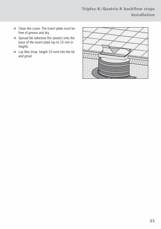
Î Clean the cover. The insert plate must be free of grease and dry.
Î Spread tile adhesive (for plastic) onto the base of the insert plate (up to 15 mm in height).
Î Lay tiles (max. height 10 mm) into the lid and grout.

24
Post-installation inspectionsTriplex-K/Quatrix-K backflow stops
4 Post-installation inspections
Following installation, the emergency flap and seal integrity must be tested (does not apply for Triplex-K cleaning pipe).
4.1 Opening and closing the shaft systemOpening the shaft system:
Î Remove protective caps from locking screws, e.g. with a slotted screwdriver (1).
Î Using an allen key (size 10 mm), turn both locking screws by about ¼ towards until they stop (2).
2.1.
Î Lift up the cover (on the side with the locking screws).
If the lifting plate is too stiff:
Î Wedge a slotted screwdriver (1) under one corner beneath the O-ring (on the side with the locking screws).
Î Lift up the cover and remove (2).
2.
1.
25
Post-installation inspectionsTriplex-K/Quatrix-K backflow stops
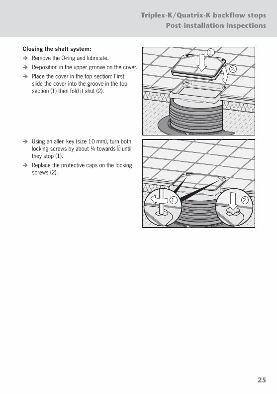
Closing the shaft system:
Î Remove the O-ring and lubricate.
Î Re-position in the upper groove on the cover.
Î Place the cover in the top section: First slide the cover into the groove in the top section (1) then fold it shut (2).
2.
1.
Î Using an allen key (size 10 mm), turn both locking screws by about ¼ towards until they stop (1).
Î Replace the protective caps on the locking screws (2).
1. 2.

26
Post-installation inspectionsTriplex-K/Quatrix-K backflow stops
4.2 Activating the emergency flap
NOTICE The emergency flap (does not apply for Triplex K, K-0) must be open for water to drain. Close the emergency flap if water backflows, e.g. in extremely heavy rain.
If the emergency flap cannot be activated correctly and easily, "Instructions for use".
Closing the emergency flap:
Î Push the red lever in flow direction until it locks (clicks audibly into place) (1).
Opening the emergency flap:
Î Push the red lever against the flow direction until it locks (2).
2.
1.
4.3 Triplex K-2: Tightness test
Properly qualified personnel must perform the tightness tests, Section 1.4 "Personnel qualification".
The test includes simulating a backflow using a test funnel (included in the scope of supply) to test the seal integrity and functional reliability of the automatic flaps.
The seal integrity of the backflow unit is deemed to be sufficient if less than 500 ml (0.5 l) of water is needed to top up the test funnel within 10 minutes.
If this is not the case, clean the backflow unit. Coarse deposits will often be the cause, "Instructions for use".
Repeat the test.
Replace the backflow unit if more than 500 ml (0.5 l) of water still has to be used to top up within 10 minutes.

27
Post-installation inspectionsTriplex-K/Quatrix-K backflow stops
Performing the test:
Î To close the emergency flap, push the red lever in flow direction until it locks (clicks audibly into place) (1).
Î Unscrew the red plug from its housing (2).
1.
2.
Î Screw the test funnel into the thread (1).
Î Fill the funnel with clean water up to the "100 mm" mark (2).
Î Top up with water if the level drops.
1.
2.
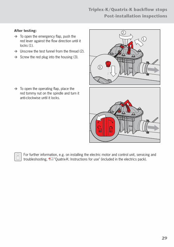
After testing:
Î To open the emergency flap, push the red lever against the flow direction until it locks (1).
Î Unscrew the test funnel from the thread (2).
Î Screw the red plug into the housing (3).
2.
1.
3.

28
Post-installation inspectionsTriplex-K/Quatrix-K backflow stops
4.4 Quatrix-K: Tightness test
Properly qualified technicians must perform the tightness tests, Section 1.4 "Personnel qualification".
The test includes simulating a backflow using a test funnel (included in the scope of supply).
The seal integrity of the backflow unit is deemed to be sufficient if less than 500 ml (0.5 l) of water is needed to top up the test funnel within 10 minutes.
If this is not the case, clean the backflow unit. Coarse deposits will often be the cause, "Quatrix-K: Instructions for use" (part of the electrics pack).
Repeat the test.
Replace the backflow unit if more than 500 ml (0.5 l) of water still has to be used to top up within 10 minutes.
Performing the test:
The sealing plug must be attached to the nipple of the sensor cable connection on the housing lid (as-delivered condition).
Î To close the operating flap (backflow flap), place the red tommy nut on the spindle and turn it clockwise until it locks (1).
Î To close the emergency flap, push the red lever in flow direction until it locks (clicks audibly into place) (2).
Î Unscrew the red locking screw from its thread (3).
2.
3.1.
Î Screw the test funnel into the thread (1).
Î Fill the funnel with clean water up to the "100 mm" mark (2).
Î Top up with water if the level drops.
1.
2.
29
Post-installation inspectionsTriplex-K/Quatrix-K backflow stops
After testing:
Î To open the emergency flap, push the red lever against the flow direction until it locks (1).
Î Unscrew the test funnel from the thread (2).
Î Screw the red plug into the housing (3).
1.
2.
3.
Î To open the operating flap, place the red tommy nut on the spindle and turn it anti-clockwise until it locks.
For further information, e.g. on installing the electric motor and control unit, servicing and troubleshooting, "Quatrix-K: Instructions for use" (included in the electrics pack).

30
Annex: Handover procedure and documentationTriplex-K/Quatrix-K backflow stops
Annex: Handover procedure and documentation
Quatrix-K
Quatrix-K handover procedure and documentation, "Quatrix-K: Instructions for use" (included in the electrics pack).
Commissioning and induction by the company performing the work in the presence of the client.
Date of commissioning:
Date of handover:
Product identification
ProductArt. no.
( Section 2.2)Serial no. (type plate)
Year built (type plate)
Nominal width DN/OD Version
Triplex K 110
125
160
with shaft system
without shaft system
Triplex K-0
Triplex K-1
Triplex K-2
Technical supervisors
Work performed by
Work accepted by Client
Name:
Contact:
Tel.:
Fax:
Email:
Address:

31
Annex: Handover procedure and documentationTriplex-K/Quatrix-K backflow stops
Check list (to be completed by the company performing the work)
Inspections Remarks OK Not OK
Installation of the unitPiping systems, connections, flow direction, supports
State of the unit Visual inspection: exterior damage, soiling
Version with shaft systemShaft system opens/closes without problems (no tension present)
Unit functionsExcl. Triplex K: Backflow flaps
Excl. Triplex K, K-0: Emergency flap
Tightness test
Induction (to be given by the company performing the work)
Induction Remarks Yes No
InductionFunctions, operation, operating tips, troubleshooting, obligatory servicing
Handover
Quatrix-K: Electrics pack
Triplex: Instructions for use
Installation instructions
Remarks:
Signature (work performed by):
Signature (work accepted by):

ACO Passavant GmbH Im Gewerbepark 11c
D 36457 Stadtlengsfeld
Tel.: + 49 36965 819-0 Fax: + 49 36965 819-361
www.aco-haustechnik.de
ACO. The future of drainage.
ACO Haustechnik