voltage equipment 08 - fuji electric
TRANSCRIPT

Information in this catalog is subject to change without notice.
5-7, Nihonbashi Odemma-cho, Chuo-ku, Tokyo, 103-0011, Japan URL http://www.fujielectric.co.jp/fcs/eng
IND
IVID
UA
L CA
TA
LOG
from
D&
C C
AT
ALO
G 20th E
ditio
n
08
LOW VOLTAGE PRODUCTS Up to 600 VoltsIndividualcatalog No.
01 Magnetic Contactors and StartersThermal Overload Relays, Solid-state Contactors
02
Industrial Relays, Industrial Control RelaysAnnunciator Relay Unit, Time Delay Relays
Manual Motor Starters and Contactors Combination Starters
Pushbuttons, Selector Switches, Pilot LightsRotary Switches, Cam Type Selector SwitchesPanel Switches, Terminal Blocks, Testing Terminals
Molded Case Circuit BreakersAir Circuit Breakers
Earth Leakage Circuit BreakersEarth Leakage Protective Relays
Measuring Instruments, Arresters, TransducersPower Factor ControllersPower Monitoring Equipment (F-MPC)
Circuit ProtectorsLow Voltage Current-Limiting Fuses
03
04
05
06
07
08
09
10
HIGH VOLTAGE PRODUCTS Up to 36kV
11Disconnecting Switches, Power FusesAir Load Break SwitchesInstrument Transformers — VT, CT
D&C CATALOG DIGEST INDEX
AC Power RegulatorsNoise Suppression FiltersControl Power Transformers
12 Vacuum Circuit Breakers, Vacuum Magnetic ContactorsProtective Relays
Limit Switches, Proximity SwitchesPhotoelectric Switches
01 02 03 04 05 06 07 08 09 10 11 12
INDIVIDUAL CATALOGfrom D&C CATALOG 20th Edition 08INDIVIDUAL CATALOG
from D&C CATALOG 20th Edition 08
CIRCUIT PROTECTORS
LOW VOLTAGE CURRENT - LIMITING FUSES
CP-P typeCircuit protectors
CP-B typeCircuit protectors
CP-V typeCircuit protectors
AFaC and BaC typesHRC fuses
BLC, CR and CS typesSuper Rapid Fuses
LOWVOLTAGE
EQUIPMENTUp to 600 Volts
CP-F typeCircuit protectors
2010-04 PDF FOLS DEC2008

08 Circuit protectors
Low voltage fuses
Page
Circuit Protectors CP31F, 32F, 33F .............................................................................................. 08/1 CP31, 31D, 32D .............................................................................................. 08/5 CP31P, 32P, 33P ............................................................................................. 08/8 CP51B, 52B, 53B ............................................................................................ 08/14 CP31E, 32E, 33E, 34E, CP31V, 32V, 33V, 34V............................................... 08/19
Low Voltage Fuses General information ......................................................................................... 08/25 Current-limiting fuses AFaC, BaC .................................................................................................. 08/26 FCF, FCK .................................................................................................... 08/29 Super rapid fuses BLC, CR, CS ............................................................................................... 08/31

MINIMUM ORDERSOrders amounting to less than ¥10,000 net per order willbe charged as ¥10,000 net per order plus freight andother charges.
WEIGHTS AND DIMENSIONSWeights and dimensions appearing in this catalog are thebest information available at the time of going to press.FUJI ELECTRIC FA has a policy of continuous productimprovement, and design changes may make thisinformation out of date.Please confirm such details before planning actualconstruction.
INFORMATION IN THIS CATALOG IS SUBJECT TOCHANGE WITHOUT NOTICE.

Fuji Electric FA components & Systems Co., Ltd./D & C CatalogInformation subject to change without notice 08/1
08
Circuit ProtectorsCP31F, 32F, 33F
CP-F slim type circuit protectors250V AC/65V DC (1-pole) 0.1A to 30A250V AC/125V DC (2-pole) 0.1A to 30A250V AC (3-pole) 0.1A to 30A
■ DescriptionFUJI's compact and high-performanceCP-F series circuit protectors incorporateFUJI's advanced technology.Their thin sizes make them ideal for useas AC/DC line switches in office andindustrial equipment.■ Features• Only 17.5mm wide — mounting space
is reduced by 30% compared withconventional types.
• AC/DC common use• Available with auxiliary switch and
alarm switch• Also available in types having inertia
delay characteristics• Trip-free mechanism• IEC rail mounting■ Standards
(File No.E96846)TÜV (IEC)(R9650230)CCC (China GB)(2003010309067080)■ Accessories● Auxiliary switch (Type W)This switch is used for ON-OFF lampindicator or control circuit.● Alarm switch (Type K)This switch can be connected to awarning lamp or buzzer to indicate whenthe circuit protector has been tripped.Auxiliary and alarm switches for low levelcircuit are also available on request.(Type W1, K1)
■ Specifications
Type CP31F CP32F CP33F
Pole 1-pole 2-pole 3-pole
Rated insulation voltage (Ui) 250V AC 250V AC 250V AC65V DC 125V DC –
Rated operatonal voltage (Ue) 240V AC 240V AC 240V AC60V DC 120V DC –
Rated current 0.1, 0.3, 0.5, 1, 2, 3, 5, 7, 10, 15, 20, 25, 30A
Rated breaking capacity 2500A at 240V AC2500A at 60V DC (1-pole)2500A at 120V DC (2-pole)
Operating characteristic Long time delay (AC circuit only)Medium time delay, Instantaneous tripping
Tripping mechanism Hydraulic-magnetic
Ambient temperature –10 to +60°CDielectric strength 2000V AC 1min
Electrical durability 10000 operations or more
Terminals Main circuit M5 (25A or over), M4 (20A or less)(Self-lifting) Auxiliary circuit M3.5
Mass (Approx.) 80g 160g 240g
Main contact Auxiliary switch/W Alarm switch/K
ON
OFF
TRIP
CP31F CP32F CP33F
KKD09-078 KKD09-079 KKD09-095
Ratings of auxiliary and alarmswitches
Standard type (Type W, K)
250V AC Resistive load: 1AInductive load: 0.5A
125V AC Resistive load: 3AInductive load: 1A
60V DC Resistive load: 1AInductive load: 0.5A
30V DC Resistive load: 2AInductive load: 1A
Minimum permissible load
For low level circuit (Type W1, K1)
24V DC 1mA12V DC 2mA 6V DC 5mA ON
LOAD
LINE
W, W1K or K1(Selectoneswitch)
Number of auxiliary and alarm switches mountable1-pole 2-pole 3-pole
K or K1 W or W1
ON
W+W orW1+W1K+W orK1+W1
ON
W or W1: At right-pole
K or K1: At left-pole
WW or W1 W1: At right-pole
and center-poleWK or W1 K1:
Aux. switch at right -poleand alarm switch at left-pole
21 20 30
13 1211
21 20 30
13 11 12

08/2Fuji Electric FA components & Systems Co., Ltd./D & C Catalog
Information subject to change without notice
Circuit ProtectorsCP31F, 32F, 33F
● Inertia delay device (Type D)This inertia delay device is designed toprevent the circuit protector fromoperating erroneously due to such inrushcurrent and to carry out an interruptionwithin the prescribed operatingcharacteristics in the face of anovercurrent.The protector does not operate evenwhen a pulse current of approx. 14 times(peak value) rated current with a pulsewidth of 10ms flows.
■ Characteristic curvesLong time delay tripping typeAC circuit only
Medium time delay tripping typeAC/DC circuit
Instantaneous tripping typeAC/DC circuit
● Snap-on mounting terminal coversFor main terminal: CP-T4For auxiliary terminal: CP-T5
CP-T4
CP-T5
1 1.5 2 3 4 5 6 7 8 910 15 20 40 60 80 100
180120
9060504030
40
20
10
20
10
1
4
2
86
4
86
0.80.60.4
0.2
0.10.080.060.04
0.02
0.01
1
2
Multiple of rated current
Min
ute
Sec
ondOpe
ratin
g tim
e
Max. value
Max. total faultclearing timeMin. value
1 1.5 2 3 4 5 6 7 8 910 15 20 40 60 80 100
180120
9060504030
40
20
10
20
10
1
4
2
86
4
86
0.80.60.4
0.2
0.10.080.060.04
0.02
0.01
AC
DC
1
2
Multiple of rated current
Min
ute
Sec
ond
Max. value
Max. total faultclearing time
Min. value
Ope
ratin
g tim
e
1 1.5 2 3 4 5 6 7 8 910 15 20 40 60 80 100
180120
9060504030
40
20
10
20
10
1
4
2
86
4
86
0.80.60.4
0.2
0.10.080.060.04
0.02
0.01
1
2
Multiple of rated current
Min
ute
Sec
ond
Max. value
Max. total faultclearing time
Min. value
Ope
ratin
g tim
e
AF92-559
Long time delay with inertia delay deviceAC circuit only
Ambient temperature compensation
Sca
le fa
ctor
of o
pera
ting
time
(%)
16012010080
60
40
-10 0 10 20 30 40 50 60Ambient temp. (˚C)
Ref. temp.: 40˚C
1 1.5 2 3 4 5 6 7 8 910 15 20 40 60 80 100
6050403020
40
20
10
0.006
10864
1
2
0.80.60.4
0.2
0.10.080.060.04
0.02
0.01
86
1
4
2
Max. value
Min. value
Multiple of rated current
Min
ute
Sec
ond
Ope
ratin
g tim
e
at 40˚C
Max. total fault clearing time
0 1 2 3 4 5 6 7 8 9 10
1000
2000
3000
4000
5000
6000Inertia delay characteristic
Pulse time (ms)
Sca
le fa
ctor
of r
ated
cur
rent
(%
)
Peak value of pulse current × 100Rated current of protector
• Scale factor of the rated current (%)
• Waveform of pulse current: Sinusoidal wave or parabolic pulse
Peakvalue ofpulse current
Pulse time
12.8
1 9.8
1223.5
21.6
2
ø3.5
R1.755.5
3.5
17.4
46.6
12.8
20.4
28.8

Fuji Electric FA components & Systems Co., Ltd./D & C CatalogInformation subject to change without notice 08/3
08CP3 1 F M / 5 W D
Basic typeCP3■ F
Number of poles1: 1-pole2: 2-pole3: 3-pole (AC circuit only)
Operating characteristicsS: Long time delay tripping (AC circuit only)M: Medium time delay trippingI: Instantaneous
Rated current0.1: 0.1A 1: 1A 10: 10A0.3: 0.3A 2: 2A 15: 15A0.5: 0.5A 3: 3A 20: 20A
5: 5A 25: 25A7: 7A 30: 30A
■ Versions
Operating CP31F (1-pole) CP32F (2-pole) CP33F (3-pole)characteristic Type Type Type
Without inertia Long time CP31FS/� CP32FS/� CP33FS/�delay device Medium time CP31FM/� CP32FM/� CP33FM/�
Instantaneous CP31FI/� CP32FI/� CP33FI/�
With inertia delay Long time CP31FS/�D CP32FS/�D CP33FS/�Ddevice Medium time CP31FM/�D CP32FM/�D CP33FM/�D
Instantaneous — — —
With standard Long time CP31FS/�W CP32FS/�W CP33FS/�Wauxiliary switch Medium time CP31FM/�W CP32FM/�W CP33FM/�W
Instantaneous CP31FI/�W CP32FI/�W CP33FI/�W
With standard Long time CP31FS/�WD CP32FS/�WD CP33FS/�WDauxiliary switch and Medium time CP31FM/�WD CP32FM/�WD CP33FM/�WDinertia delay device Instantaneous — — —
With standard Long time CP31FS/�K CP32FS/�K CP33FS/�Kalarm switch Medium time CP31FM/�K CP32FM/�K CP33FM/�K
Instantaneous CP31FI/�K CP32FI/�K CP33FI/�K
With standard Long time CP31FS/�KD CP32FS/�KD CP33FS/�KDalarm switch and Medium time CP31FM/�KD CP32FM/�KD CP33FM/�KDinertia delay device Instantaneous — — —
With auxiliary switch Long time CP31FS/�W1 CP32FS/�W1 CP33FS/�W1for low level circuit Medium time CP31FM/�W1 CP32FM/�W1 CP33FM/�W1
Instantaneous CP31FI/�W1 CP32FI/�W1 CP33FI/�W1
With auxiliary switch Long time CP31FS/�W1D CP32FS/�W1D CP33FS/�W1Dfor low level circuit Medium time CP31FM/�W1D CP32FM/�W1D CP33FM/�W1Dand inertia delay device Instantaneous — — —
With alarm switch Long time CP31FS/�K1 CP32FS/�K1 CP33FS/�K1for low level circuit Medium time CP31FM/�K1 CP32FM/�K1 CP33FM/�K1
Instantaneous CP31FI/�K1 CP32FI/�K1 CP33FI/�K1
With alarm switch Long time CP31FS/�K1D CP32FS/�K1D CP33FS/�K1Dfor low level circuit Medium time CP31FM/�K1D CP32FM/�K1D CP33FM/�K1Dand inertia delay device Instantaneous — — —
Note : � Enter the rated current in the � mark of the type number. 0.1A: 0.1, 0.3A; 0.3, 0.5A: 0.5 ------ 30A: 30
■ Type number nomenclature
Inertia delay deviceBlank: Without inertia delay deviceD: With inertia delay device
(Except instantaneous type)
AccessoriesBlank: Without accessoryW: With standard auxiliary switchW1: With auxiliary switch for low level circuitK: With standard alarm switchK1: With alarm switch for low level circuit
WW: With two standard auxiliary switches
W1W1: With two auxiliary switches for low level circuits
WK: With standard auxiliary and alarm switches
W1K1: With auxiliary and alarm switchesfor low level circuit
Circuit ProtectorsCP31F, 32F, 33F

08/4Fuji Electric FA components & Systems Co., Ltd./D & C Catalog
Information subject to change without notice
Circuit ProtectorsCP31F, 32F, 33F
■ Dimensions, mm1-pole 2-pole 3-pole
Panel drilling
54
4.5
Main terminalM4: 20A or lessM5: 25A or more
Main terminalM4: 20A or lessM5: 25A or more
12
54
TRIPindicator
TRIPindicator
47
54
29.5
Mounting rail 35mm width IEC standard
27
5
63
5
24.54658.1
67 56 45
ONTRIPOFF
5
φ 4.5φ 4.5φ
Mounting rail 35mm width IEC standard
27
5
63
5
24.54658.1
67 56 50.7
ONTRIP
OFF
5
17.5max. Auxiliary terminal M3.5With Aux. switch or alarm switchAuxiliary terminal M3.5With Aux. switch or alarm switch
Auxiliary terminal M3.5With Aux. switch or alarm switch
Auxiliary terminal M3.5With Aux. switch
Auxiliary terminal M3.5With Aux. switch
Auxiliary terminal M3.5With Aux. switch
52.5 max. 35 max.
54
47 2-M4
54
29.5 2-M4
54
12 2-M4
Fuji Electric FA components & Systems Co., Ltd./D & C CatalogInformation subject to change without notice 08/5
08
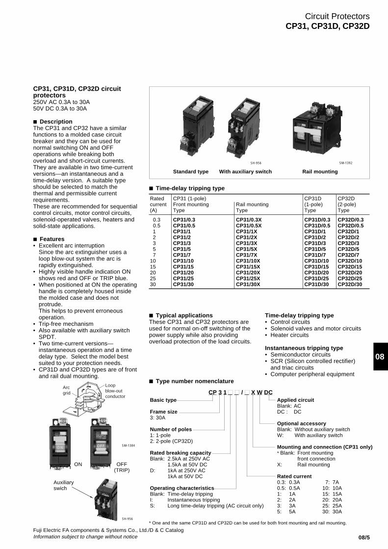
CP31, CP31D, CP32D circuitprotectors250V AC 0.3A to 30A50V DC 0.3A to 30A
■ DescriptionThe CP31 and CP32 have a similarfunctions to a molded case circuitbreaker and they can be used fornormal switching ON and OFFoperations while breaking bothoverload and short-circuit currents.They are available in two time-currentversions—an instantaneous and atime-delay version. A suitable typeshould be selected to match thethermal and permissible currentrequirements.These are recommended for sequentialcontrol circuits, motor control circuits,solenoid-operated valves, heaters andsolid-state applications.
■ Features• Excellent arc interruption
Since the arc extinguisher uses aloop blow-out system the arc israpidly extinguished.
• Highly visible handle indication ONshows red and OFF or TRIP blue.
• When positioned at ON the operatinghandle is completely housed insidethe molded case and does notprotrude.This helps to prevent erroneousoperation.
• Trip-free mechanism• Also available with auxiliary switch
SPDT.• Two time-current versions—
instantaneous operation and a timedelay type. Select the model bestsuited to your protection needs.
• CP31D and CP32D types are of frontand rail dual mounting.
Standard type With auxiliary switch Rail mounting
SH-956 SM-1392
■ Type number nomenclature
CP 3 1 ■ ■ / ■ X W DCBasic type
Frame size3: 30A
Number of poles1: 1-pole2: 2-pole (CP32D)
Rated breaking capacityBlank: 2.5kA at 250V AC
1.5kA at 50V DCD: 1kA at 250V AC
1kA at 50V DC
Operating characteristicsBlank: Time-delay trippingI: Instantaneous trippingS: Long time-delay tripping (AC circuit only)
Applied circuitBlank: ACDC : DC
Optional accessoryBlank: Without auxiliary switchW: With auxiliary switch
Mounting and connection (CP31 only)* Blank: Front mounting
front connectionX: Rail mounting
Rated current0.3: 0.3A 7: 7A0.5: 0.5A 10: 10A1: 1A 15: 15A2: 2A 20: 20A3: 3A 25: 25A5: 5A 30: 30A
■ Time-delay tripping type
Rated CP31 (1-pole) CP31D CP32Dcurrent Front mounting Rail mounting (1-pole) (2-pole)(A) Type Type Type Type
0.3 CP31/0.3 CP31/0.3X CP31D/0.3 CP32D/0.3 0.5 CP31/0.5 CP31/0.5X CP31D/0.5 CP32D/0.5 1 CP31/1 CP31/1X CP31D/1 CP32D/1 2 CP31/2 CP31/2X CP31D/2 CP32D/2 3 CP31/3 CP31/3X CP31D/3 CP32D/3 5 CP31/5 CP31/5X CP31D/5 CP32D/5 7 CP31/7 CP31/7X CP31D/7 CP32D/710 CP31/10 CP31/10X CP31D/10 CP32D/1015 CP31/15 CP31/15X CP31D/15 CP32D/1520 CP31/20 CP31/20X CP31D/20 CP32D/2025 CP31/25 CP31/25X CP31D/25 CP32D/2530 CP31/30 CP31/30X CP31D/30 CP32D/30
Circuit ProtectorsCP31, CP31D, CP32D
* One and the same CP31D and CP32D can be used for both front mounting and rail mounting.
■ Typical applicationsThese CP31 and CP32 protectors areused for normal on-off switching of thepower supply while also providingoverload protection of the load circuits.
Time-delay tripping type• Control circuits• Solenoid valves and motor circuits• Heater circuits
Instantaneous tripping type• Semiconductor circuits• SCR (Silicon controlled rectifier)
and triac circuits• Computer peripheral equipment
SH-956
SM-1384
ON OFF(TRIP)
Auxiliaryswich
Arcgrid
Loopblow-outconductor

08/6Fuji Electric FA components & Systems Co., Ltd./D & C Catalog
Information subject to change without notice
■ OperationThe operation of the magnetic overloadrelease of the CP31, CP31D and CP32Dcircuit protectors are as shown in thesectional diagram Fig. 1. The magnetictripping element of the circuit protector issimple—a solenoid coil wound around ahermetically-sealed non-magneticcylinder containing a spring-loadedmovable iron core and a silicon fluid.When currents less than the rated valueflow no movement occurs in either thearmature or iron core.However, when a sustained overcurrentoccurs the magnetic field is increased.This causes the iron core to move alongthe cylinder. Once the core reaches theopposite end of the cylinder thearmature is attracted which causes theprotector to trip as shown in Fig. 2 and3.When a short circuit occurs themagnetic flux produced in the coil aloneis strong enough to attract the armatureregardless of core position. Thiscauses circuit to be interruptedinstantaneously. (Fig. 4)
■ Adaptor for flush mounting/CP-E1These circuit protectors can be modifiedfor flush mounting use by a snap-fittingadaptor CP-E1.
Flush mounting Front mounting
■ Auxiliary switch
Main contact Auxiliary contact
ON
OFF or Trip
■ Specifications
Description CP31 CP31D CP32D
Pole 1-pole 1-pole 2-poleFrame size 30 Amps. 30 Amps.Rated insulation voltage 250V AC, 50V DC 250V AC, 50V DC(Ui)Rated operational voltage 250V AC, 50V DC 250V AC, 50V DC(Ue)Rated current 0.3, 0.5, 1, 2, 3, 5, 7, 0.3, 0.5, 1, 2, 3, 5,
10, 15, 20, 25, 30A 7, 10, 15, 20, 25, 30A
Rated breaking 2500A at 250V AC 1000A at 250V ACcapacity 1500A at 50V DC 1000A at 50V DC
Operating characteristic Time-delay tripping Time-delay trippingInstantaneous tripping Instantaneous trippingLong time delay tripping Long time delay tripping
Ambient temperature –10˚C to +60˚C –10˚C to +60˚CDielectric strength 2000V AC 1min. 2000V AC 1min.
Mechanical durability 10000 operations 6000 operationsElectrical durability 10000 operations 6000 operations
Mass Approx. 100g Approx. 100g (1-pole), 200g (2-pole)
Note: Specify DC only when ordering circuit protectors for DC circuits.
■ Characteristic curve
Auxiliary contact ratings
Resistive load: 1A250V AC Inductive load: 0.5AResistive load: 3A125V AC Inductive load: 1AResistive load: 1A 50V DC Inductive load: 0.5AResistive load: 2A 30V DC Inductive load: 1A
Ambient temperature compensation(Time delay tripping type)
Fig. 1 Normal load
Fig. 2 Overcurrent
Fig. 3 Overcurrent trip
Fig. 4 Short-circuit current trip ■ Snap-on mounting terminal coversFor main terminal: CP-T1For auxiliary terminal: CP-T2
Circuit ProtectorsCP31, CP31D, CP32D
ArmatureSpring
Solenoid coil
Cylinder
Core
YokeSilicon fluid
20
2130
2021
30 Sca
le fa
ctor
of o
pera
ting
time
(%)
Ambient temp. (°C)
-10 0 10 20 30 40 50 60
40
6080
100120160200
300
Ref. temp.: 40°C
CP-E1SM-1385
Mul t ip le o f ra ted cur ren t
0.0060.01
0.020.040.060.1
0.20.40.6
1246
20
20401
246
10204060
1 1.5 2 3 4 6 8 10 20 40 60 8010030
Op
era
tin
g t
ime
Sec
ond
Min
ute
Instantaneoustripping type
Max. total fault cleaning time
at 40˚C
Time delay tripping type
Long time delay tripping type

Fuji Electric FA components & Systems Co., Ltd./D & C CatalogInformation subject to change without notice 08/7
08
■ Dimensions, mm● CP31Front mounting type
● CP31/WWith auxiliary switch
● CP31/XRail mounting type
Mounting rail length: 900mm
Type Material Mounting pitch(Screw size)
TH35-7.5AL Aluminium 200mm (M5)TH35-15AL Aluminium 400mm (M5)
Clamp TS-XT
● CP31DFront mounting/Rail mounting type
● CP31D/WWith auxiliary switch
● CP31, CP31DFlush mounting type
● CP32DFront mounting/Rail mounting type
● CP32D/WWith auxiliary switch Size of conductors
Type of Main Auxiliaryterminal terminal terminal
Terminal screw* M4 M3.5
Connectable 1.25–5.5mm2 1.25–2mm2
wire sizes
Max. width of 9.8mm 6.8mmapplicable (R1.25–4 to (R2–3.5)crimp terminal R5.5–4)
Tightening 1.0–1.3N·m 0.8–0.9N·mtorqueNote: * Terminal screws are the self-lifting to
facilitate wiring.
Mass: Approx. 100g
Mass: Approx. 200g
Mass: Approx. 100g
Circuit ProtectorsCP31, CP31D, CP32D
25
6454 6046
12
54
12
27.5
65218
ø4.5
7
ON
OFF
max6.5
Terminal M4
2-M4 (ø5)
Paneldrilling
25
6454 6046
12
54
12
27.5
655510
218
ø4.5
7
ON
OFF
max6.5
Terminal M4
2-M4 (ø5)
Auxiliary terminalM3.5
Panel drilling
5
27.5
6521
Mounting rail width 35mm IEC standard
ON
OFF
max6.5
3.5 (TH35-7.5AL)11 (TH35-15AL)
Terminal M4
25
64
5
54 46
12 27.5
6521
ø4.5
7
Mounting rail width 35mm IEC standard
ON
OFF
max6.5
Terminal M4
3.5 (TH35-7.5AL)11 (TH35-15AL)
54
122-M4 (ø5)
Mounting hole for front mounting
Panel drilling
25
6454 6046
12
54
12
8
ø4.5
7
2-M4 (ø5)
Auxiliary terminalM3.5
Mounting hole for front mounting
5
27.5
6521
Mounting rail width 35mm IEC standard
ON
OFF
max6.5
Terminal M4
3.5 (TH35-7.5AL)11 (TH35-15AL)
Panel drilling
60
9max.
6.5
TerminalM3(25.5)
25 4
525.5
46 54
47 6262 70(47)
CL
2-ø4
R2 or less
ON
OFF
Panel
Aux.swich
Panel cutting
CL
25
64
5
46
25 27.5
65
37
21
ø4.5
7
max.9
Terminal M4
2550
54
54
2-M4 (ø5)
Mounting rail width 35mm IEC standard
3.5 (TH35-7.5AL)11 (TH35-15AL)
Panel drilling
5510
Auxiliary M3.5
2-M4 (ø5)
CL
25
64
5
46
25 27.5
65
37
5
21
ø4.5
7
Mounting rail width 35mm IEC standard
max.9
Terminal M4
2550
54
54
Mounting hole for front mounting
3.5 (TH35-7.5AL)11 (TH35-15AL)
Panel drilling
■ Ordering informationSpecify the following:1. Type number

08/8Fuji Electric FA components & Systems Co., Ltd./D & C Catalog
Information subject to change without notice
Circuit ProtectorsCP31P, 32P, 33P
CP-P circuit protectors250V AC 0.3A to 25A65V DC 0.3A to 25A
■ DescriptionCP-P circuit protectors are ideal forelectronic circuit protection. The spacerequired per pole is approximately 30%less than that for CP-E models allowingsignificant space savings. Application atany one of 12 rated currents in the range0.3A to 25A is possible. CP-P circuitprotectors have been approved byand TÜV Standards.■ Features• The mounting space is approximately
30% less than that required with CP-Emodels, and the width per pole hasbeen reduced by approximately 15%.
• Conforms to IEC Standards. (Conformsto CE markings.)
• and TÜV approved.• Operated with an easy-to-use toggle
handle.• Male tab soldering, and right angle
terminals are available.■ Standards
(File No.E96846)TÜV (IEC)(R9750278)■ Accessories● Auxiliary switch (Type W)This switch is used for indicator lamp orcontrol circuit.● Alarm switch (Type K)This switch can be connected to awarning lamp or buzzer to indicate whenthe circuit protector has been tripped.
Auxiliary and alarm switches for low levelcircuit are also available on request.(Type W1, K1)
■ Specifications
Type CP31P CP32P CP33P CP31P-R
Pole 1-pole 2-pole 3-pole 1-pole
Rated insulation voltage (Ui) 250V AC 50/60Hz, 65V DC
Rated operational voltage (Ue) 240V AC, 60V DC
Rated current 0.3, 0.5, 0.75, 1, 2, 3, 5, 7.5, 10, 15, 20, 25A
Rated breaking capacity 1000A at 240V AC1000A at 60V DC
Operating characteristic Long time delay, Medium time delayShort time delay, Instantaneous tripping
Tripping mechanism Hydraulic-magnetic
Ambient temperature -10˚C to +60˚C
Electrical durability 10000 operations
Terminals Main circuit Tab Right angleAuxiliary circuit Soldering Right angle
Accessories Auxiliary switch (W, W1) AvailableAlarm switch (K, K1) Available
Mass (Approx.) 40g 85g 130g 40g
Main contact Auxiliary switch Alarm switch
ON
OFF
TRIP
Ratings of auxiliary and alarmswitches
Standard type (Type W, K)
250V AC Resistive load: 3AInductive load: 2A
125V AC Resistive load: 3AInductive load: 2A
30V DC Resistive load: 3AInductive load: 2A
Minimum permissible load
For low level circuit (Type W1, K1)
24V DC 1mA12V DC 2mA 6V DC 5mA
C NO NC
C NCNO
C NO NC
C NO NC
KKD09-086
CP31P CP32P CP33P CP31P-RAF99-297KKD09-083 KKD09-099

Fuji Electric FA components & Systems Co., Ltd./D & C CatalogInformation subject to change without notice 08/9
08
■ Versions
Operating CP31P (1-pole) CP32P (2-pole) CP33P (3-pole)characteristic Type Type Type
Applied circuit AC Long time CP31PS/ ■ CP32PS/ ■ CP33PS/ ■
Medium time CP31PM/ ■ CP32PM/ ■ CP33PM/ ■
Short time CP31PF/ ■ CP32PF/ ■ CP33PF/ ■
Instantaneous CP31PI/ ■ CP32PI/ ■ CP33PI/ ■
Applied circuit DC Long time CP31PS/ DC■ CP32PS/ DC■ CP33PS/ DC■
Medium time CP31PM/ DC■ CP32PM/ DC■ CP33PM/ DC■
Short time CP31PF/ DC■ CP32PF/ DC■ CP33PF/ DC■
Instantaneous CP31PI/ DC■ CP32PI/ DC■ CP33PI/ DC■
With standard Long time CP31PS/ W■ CP32PS/ W■ CP33PS/ W■
auxiliary switch Medium time CP31PM/ W■ CP32PM/ W■ CP33PM/ W■
Short time CP31PF/ W■ CP32PF/ W■ CP33PF/ W■
Instantaneous CP31PI/ W■ CP32PI/ W■ CP33PI/ W■
Applied circuit DC Long time CP31PS/ WDC■ CP32PS/ WDC■ CP33PS/ WDC■
Medium time CP31PM/ WDC■ CP32PM/ WDC■ CP33PM/ WDC■
Short time CP31PF/ WDC■ CP32PF/ WDC■ CP33PF/ WDC■
Instantaneous CP31PI/ WDC■ CP32PI/ WDC■ CP33PI/ WDC■
With standard Long time CP31PS/ K■ CP32PS/ K■ CP33PS/ K■
alarm switch Medium time CP31PM/ K■ CP32PM/ K■ CP33PM/ K■
Short time CP31PF/ K■ CP32PF/ K■ CP33PF/ K■
Instantaneous CP31PI/ K■ CP32PI/ K■ CP33PI/ K■
Applied circuit DC Long time CP31PS/ KDC■ CP32PS/ KDC■ CP33PS/ KDC■
Medium time CP31PM/ KDC■ CP32PM/ KDC■ CP33PM/ KDC■
Short time CP31PF/ KDC■ CP32PF/ KDC■ CP33PF/ KDC■
Instantaneous CP31PI/ KDC■ CP32PI/ KDC■ CP33PI/ KDC■
With auxiliary switch Long time CP31PS/ W1■ CP32PS/ W1■ CP33PS/ W1■
for low level circuit Medium time CP31PM/ W1■ CP32PM/ W1■ CP33PM/ W1■
Short time CP31PF/ W1■ CP32PF/ W1■ CP33PF/ W1■
Instantaneous CP31PI/ W1■ CP32PI/ W1■ CP33PI/ W1■
Applied circuit DC Long time CP31PS/ W1DC■ CP32PS/ W1DC■ CP33PS/ W1DC■
Medium time CP31PM/ W1DC■ CP32PM/ W1DC■ CP33PM/ W1DC■
Short time CP31PF/ W1DC■ CP32PF/ W1DC■ CP33PF/ W1DC■
Instantaneous CP31PI/ W1DC■ CP32PI/ W1DC■ CP33PI/ W1DC■
With alarm switch Long time CP31PS/ K1■ CP32PS/ K1■ CP33PS/ K1■
for low level circuit Medium time CP31PM/ K1■ CP32PM/ K1■ CP33PM/ K1■
Short time CP31PF/ K1■ CP32PF/ K1■ CP33PF/ K1■
Instantaneous CP31PI/ K1■ CP32PI/ K1■ CP33PI/ K1■
Applied circuit DC Long time CP31PS/ K1DC■ CP32PS/ K1DC■ CP33PS/ K1DC■
Medium time CP31PM/ K1DC■ CP32PM/ K1DC■ CP33PM/ K1DC■
Short time CP31PF/ K1DC■ CP32PF/ K1DC■ CP33PF/ K1DC■
Instantaneous CP31PI/ K1DC■ CP32PI/ K1DC■ CP33PI/ K1DC■
Notes : Enter the rated current in the mark of the type number. 0.3A: 0.3, 0.5A: 0.5 ------ 25A: 25■ Enter the main circuit terminal in the ■ mark.
Circuit ProtectorsCP31P, 32P, 33P

08/10Fuji Electric FA components & Systems Co., Ltd./D & C Catalog
Information subject to change without notice
Circuit ProtectorsCP31P, 32P, 33P
CP3 1 P M / 0.3 W DC P
Basic type
Number of poles1: 1-pole2: 2-pole3: 3-pole
Operating characteristicsS: Long time delay trippingM: Medium time delay trippingF: Short time delay trippingI: Instantaneous
Rated current0.3: 0.3A 2: 2A 10: 10A0.5: 0.5A 3: 3A 15: 15A0.75:0.75A 5: 5A 20: 20A1: 1A 7.5:7.5A 25: 25A
■ Type number nomenclature
Main circuit terminalBlank: Male tab terminalP: Soldering terminalR: Right angle terminal
Applied circuitBlank: AC DC: DC circuit
AccessoriesBlank: Without accessoryW: With standard auxiliary switchK: With standard alarm switchW1: With auxiliary switch for low level circuitK1: With alarm switch for low level circuit
■ Characteristic curves
100 200 300 400 500 600 700 800 9001000
1000
100
10
1
.1
.01
.001
at 25˚C
Multiple of rated current (%)
Ope
ratin
g tim
e (s
ec.)
Multiple of rated current (%)
Ope
ratin
g tim
e (s
ec.)
100 200 300 400 500 600 700 800 9001000
1000
100
10
1
.1
.01
.001
at 25˚C
100 200 300 400 500 600 700 800 9001000
1000
100
10
1
.1
.01
.001
at 25˚C
100 200 300 400 500 600 700 800 9001000
1000
100
10
1
.1
.01
.001
at 25˚C
AC circuit
Long time delay (S) Medium time delay (M)
Short time delay (F) Instantaneous (I)
Multiple of rated current (%)
Ope
ratin
g tim
e (s
ec.)
Multiple of rated current (%)
Ope
ratin
g tim
e (s
ec.)
Max. value
Min. value
Max. value
Min. value
Max. value
Min. value
Max. value
Min. value
Sca
le fa
ctor
of o
pera
ting
time
(%)
40
60
80100
200
300
-10 0 10 20 25 30 40 50 60
Ambient temp. (˚C)
Ambient temperature compensation
Ref. temp.: 25˚C

Fuji Electric FA components & Systems Co., Ltd./D & C CatalogInformation subject to change without notice 08/11
08
100 200 300 400 500 600 700 800 9001000
1000
100
10
1
.1
.01
.001
at 25˚C
100 200 300 400 500 600 700 800 9001000
1000
100
10
1
.1
.01
.001
at 25˚C
100 200 300 400 500 600 700 800 9001000
1000
100
10
1
.1
.01
.001
at 25˚C
100 200 300 400 500 600 700 800 9001000
1000
100
10
1
.1
.01
.001
at 25˚C
DC circuit
Long time delay (S) Medium time delay (M)
Short time delay (F) Instantaneous (I)
Multiple of rated current (%)
Ope
ratin
g tim
e (s
ec.)
Multiple of rated current (%)
Ope
ratin
g tim
e (s
ec.)
Multiple of rated current (%)
Ope
ratin
g tim
e (s
ec.)
Multiple of rated current (%)
Ope
ratin
g tim
e (s
ec.)
Max. value
Min. value
Max. value
Min. value
Max. value
Min. value
Max. value
Min. value
Circuit ProtectorsCP31P, 32P, 33P
■ Characteristic curves

08/12Fuji Electric FA components & Systems Co., Ltd./D & C Catalog
Information subject to change without notice
Circuit ProtectorsCP31P, 32P, 33P
■ Dimensions, mm1-pole 2-pole 3-pole
Series trip
View from back View from back View from back
With auxiliary or alarm switch
ø13.6
16.4max.
32
20
M3 Depth 4.6
ø13.6
32.6 max.
32
20
M3 Depth 4.6
16
49 max.
16 16
ø13.6
32
20
M3 Depth 4.6
Series trip
Main terminal Thickness: 0.8 Width: 6.3
42 42 42
Series trip
Main terminal Thickness: 0.8 Width: 6.3
With auxiliary or alarm switch
Main terminal Thickness: 0.8, width: 6.3
Aux. terminal Thickness: 1 Width: 2.8
42
Aux. terminalThickness: 1, width: 2.8
42
With auxiliary or alarm switch
Aux. terminal (for aux. switch)Thickness: 1 Width: 2.8
Main terminal Thickness: 0.8 Width: 6.3
Aux. terminal (for alarm)Thickness: 1 Width: 2.8
42
50
38
3.5
35
38
P
42
16.9
LOAD
LINE
50
38
5
3.5
15.4
7.8
8.7
35
38
P
42
16.9
LOAD
LINE
Line side
Load side
32±0
.2
20±0
.2
ø14 +0.4 0
2-ø4±0.2
Line side
Load side
32±0
.2
20±0
.2
ø14 +0.4 0
4-ø4±0.2
16±0.2
Line side
6-ø4±0.2
32±0
.2
20±0
.2
ø14
Load side
16±0.2 16±0.2
+0.4 0
Series trip
Main terminal Thickness: 0.8 Width: 6.3
With auxiliary or alarm switch
Main terminal Thickness: 0.8 Width: 6.3
Panel drilling 1-pole 2-pole 3-pole

Fuji Electric FA components & Systems Co., Ltd./D & C CatalogInformation subject to change without notice 08/13
08
Circuit ProtectorsCP31P, 32P, 33P
16.9
38
5 42
43.64
3
13.62.
88.
71.
2
8 5.1
1.2
7.9
15.4
3.4
35.2
LOAD
LINE
16
ø13.6
32.6 max.16.4 max.
ø13.6
20
3242
16
ø13.6
16
49 max.
1
2.85
5
0.5
1.25
4-ø1.9
5.1
1.2
7.9
15.4
35.2
8.7
3.4
3
16.9
38
42
0.8
ø13.6 4
13.69.
6
3.4
35.2
15.2
7.6
20
1.2
1.2
12.5
3242
16.4 max.
LOAD
LINE
50.41.2
A A
0.8
0.8
4
4
45.40.5
1.21.2
5
12.5
13.6
545
.4
9.6 15.2
7.6
35.2
9-ø1.9
6.25
Soldering terminal(With auxiliary terminal)
Main terminal Thickness: 0.8
Aux. terminal
Right angle terminal(With auxiliary terminal)
Aux. terminal (Enlarged)
Aux. terminal Thickness: 0.5
Handle center
Panel drilling
Panel drilling (1-pole)
Printed board
BracketNot suppled.Prease prepare it oncustomer's side.
12.5
min
.
M3 Depth 4.6 M3 Depth 4.6 M3 Depth 4.6
Main terminal Thickness: 0.8
■ Dimensions, mm1-pole 2-pole 3-pole

08/14Fuji Electric FA components & Systems Co., Ltd./D & C Catalog
Information subject to change without notice
Circuit ProtectorsCP51B, 52B, 53B
50A frame size circuit protectors250V AC 0.3A to 50A65V DC 0.3A to 50A
■ Features• Available with ratings from 0.3A to 50A.• Conforms to IEC Standards. (Conforms
to CE markings.)• and TÜV approved.• Rated breaking capacity of 1,500A at
240V AC.• Stud terminals used.■ Standards (File No.E96846)TÜV (IEC)(R9750278)■ Accessories● Auxiliary switch (Type W)This switch is used for ON-OFF lampindicator or control circuit.● Alarm switch (Type K)This switch can be connected to awarning lamp or buzzer to indicate whenthe circuit protector has been tripped.
Auxiliary and alarm switch for low levelcircuit are also available on request.(Type W1, K1)
■ Specifications
Type CP51B CP52B CP53B
Pole 1-pole 2-pole 3-pole
Rated insulation voltage (Ui) 250V AC 50/60Hz, 65V DC
Rated operational voltage (Ue) 240V AC, 60V DC
Rated current 0.3, 0.5, 0.75, 1, 2, 3, 5, 7.5, 10, 15, 20, 25, 30,40, 50A
Rated breaking capacity 1500A at 240V AC1000A at 60V DC
Operating characteristic Long time delay, Medium time delayShort time delay, Instantaneous tripping
Tripping mechanism Hydraulic-magnetic
Ambient temperature -10˚C to +60˚C
Electrical durability 10000 operations
Terminals Main circuit Round studAuxiliary circuit Soldering
Accessories Auxiliary switch (W, W1) AvailableAlarm switch (K, K1) Available
Mass (Approx.) 80g 180g 280g
Main contact Auxiliary switch/W Alarm switch/K
ON
OFF
TRIP
KKD09-084
Ratings of auxiliary and alarmswitches
Standard type (Type W, K)
250V AC Resistive load: 3AInductive load: 2A
125V AC Resistive load: 3AInductive load: 2A
30V DC Resistive load: 3AInductive load: 2A
Minimum permissible load
Low level circuit (Type W1, K1)
24V DC 1mA12V DC 2mA6V DC 5mA
C NO NC
C NCNO
C NO NC
C NO NC
CP51B CP52B CP53BKKD09-092 KKD09-096
Fuji Electric FA components & Systems Co., Ltd./D & C CatalogInformation subject to change without notice 08/15
08
Circuit ProtectorsCP51B, 52B, 53B
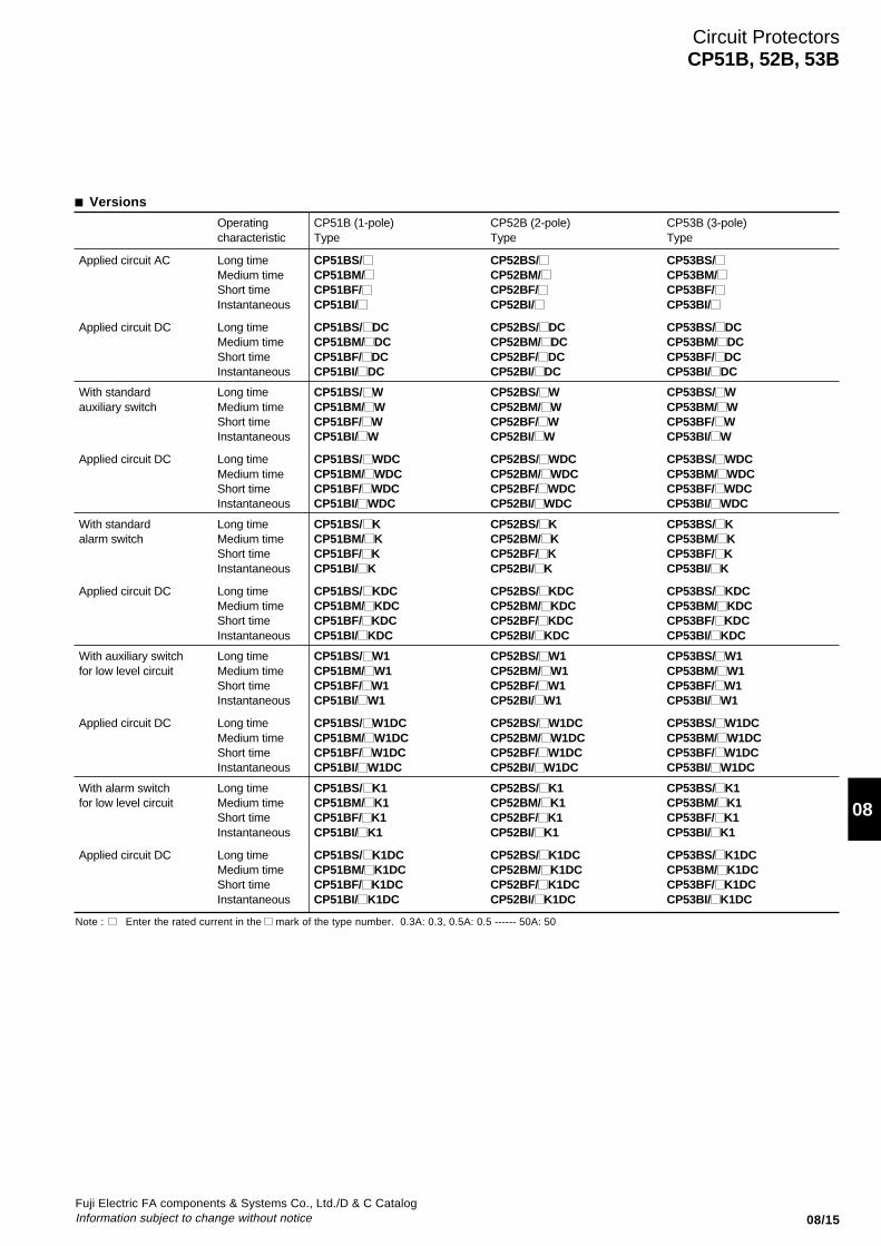
■ Versions
Operating CP51B (1-pole) CP52B (2-pole) CP53B (3-pole)characteristic Type Type Type
Applied circuit AC Long time CP51BS/ CP52BS/ CP53BS/Medium time CP51BM/ CP52BM/ CP53BM/Short time CP51BF/ CP52BF/ CP53BF/Instantaneous CP51BI/ CP52BI/ CP53BI/
Applied circuit DC Long time CP51BS/ DC CP52BS/ DC CP53BS/ DCMedium time CP51BM/ DC CP52BM/ DC CP53BM/ DCShort time CP51BF/ DC CP52BF/ DC CP53BF/ DCInstantaneous CP51BI/ DC CP52BI/ DC CP53BI/ DC
With standard Long time CP51BS/ W CP52BS/ W CP53BS/ Wauxiliary switch Medium time CP51BM/ W CP52BM/ W CP53BM/ W
Short time CP51BF/ W CP52BF/ W CP53BF/ WInstantaneous CP51BI/ W CP52BI/ W CP53BI/ W
Applied circuit DC Long time CP51BS/ WDC CP52BS/ WDC CP53BS/ WDCMedium time CP51BM/ WDC CP52BM/ WDC CP53BM/ WDCShort time CP51BF/ WDC CP52BF/ WDC CP53BF/ WDCInstantaneous CP51BI/ WDC CP52BI/ WDC CP53BI/ WDC
With standard Long time CP51BS/ K CP52BS/ K CP53BS/ Kalarm switch Medium time CP51BM/ K CP52BM/ K CP53BM/ K
Short time CP51BF/ K CP52BF/ K CP53BF/ KInstantaneous CP51BI/ K CP52BI/ K CP53BI/ K
Applied circuit DC Long time CP51BS/ KDC CP52BS/ KDC CP53BS/ KDCMedium time CP51BM/ KDC CP52BM/ KDC CP53BM/ KDCShort time CP51BF/ KDC CP52BF/ KDC CP53BF/ KDCInstantaneous CP51BI/ KDC CP52BI/ KDC CP53BI/ KDC
With auxiliary switch Long time CP51BS/ W1 CP52BS/ W1 CP53BS/ W1for low level circuit Medium time CP51BM/ W1 CP52BM/ W1 CP53BM/ W1
Short time CP51BF/ W1 CP52BF/ W1 CP53BF/ W1Instantaneous CP51BI/ W1 CP52BI/ W1 CP53BI/ W1
Applied circuit DC Long time CP51BS/ W1DC CP52BS/ W1DC CP53BS/ W1DCMedium time CP51BM/ W1DC CP52BM/ W1DC CP53BM/ W1DCShort time CP51BF/ W1DC CP52BF/ W1DC CP53BF/ W1DCInstantaneous CP51BI/ W1DC CP52BI/ W1DC CP53BI/ W1DC
With alarm switch Long time CP51BS/ K1 CP52BS/ K1 CP53BS/ K1for low level circuit Medium time CP51BM/ K1 CP52BM/ K1 CP53BM/ K1
Short time CP51BF/ K1 CP52BF/ K1 CP53BF/ K1Instantaneous CP51BI/ K1 CP52BI/ K1 CP53BI/ K1
Applied circuit DC Long time CP51BS/ K1DC CP52BS/ K1DC CP53BS/ K1DCMedium time CP51BM/ K1DC CP52BM/ K1DC CP53BM/ K1DCShort time CP51BF/ K1DC CP52BF/ K1DC CP53BF/ K1DCInstantaneous CP51BI/ K1DC CP52BI/ K1DC CP53BI/ K1DC
Note : Enter the rated current in the mark of the type number. 0.3A: 0.3, 0.5A: 0.5 ------ 50A: 50
08/16Fuji Electric FA components & Systems Co., Ltd./D & C Catalog
Information subject to change without notice
Circuit ProtectorsCP51B, 52B, 53B
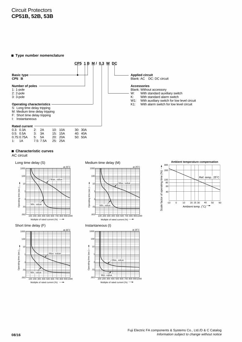
CP5 1 B M / 0.3 W DC
Basic typeCP5■ B
Number of poles1: 1-pole2: 2-pole3: 3-pole
Operating characteristicsS: Long time delay trippingM: Medium time delay trippingF: Short time delay trippingI: Instantaneous
Rated current0.3: 0.3A 2: 2A 10: 10A 30: 30A0.5: 0.5A 3: 3A 15: 15A 40: 40A0.75:0.75A 5: 5A 20: 20A 50: 50A1: 1A 7.5: 7.5A 25: 25A
■ Type number nomenclature
Applied circuitBlank: AC DC: DC circuit
AccessoriesBlank: Without accessoryW: With standard auxiliary switchK: With standard alarm switchW1: With auxiliary switch for low level circuitK1: With alarm switch for low level circuit
■ Characteristic curves
100 200 300 400 500 600 700 800 9001000
1000
100
10
1
.1
.01
.001
at 25˚C
100 200 300 400 500 600 700 800 9001000
1000
100
10
1
.1
.01
.001
at 25˚C
100 200 300 400 500 600 700 800 9001000
1000
100
10
1
.1
.01
.001
at 25˚C
100 200 300 400 500 600 700 800 9001000
1000
100
10
1
.1
.01
.001
at 25˚C
Multiple of rated current (%)
Ope
ratin
g tim
e (s
ec.)
Multiple of rated current (%)
Ope
ratin
g tim
e (s
ec.)
AC circuit
Long time delay (S) Medium time delay (M)
Short time delay (F) Instantaneous (I)
Ope
ratin
g tim
e (s
ec.)
Multiple of rated current (%)
Ope
ratin
g tim
e (s
ec.)
Multiple of rated current (%)
Max. value
Min. value
Max. value
Min. value
Max. value
Min. value
Max. value
Min. value
Sca
le fa
ctor
of o
pera
ting
time
(%)
40
60
80100
200
300
-10 0 10 20 25 30 40 50 60
Ambient temp. (˚C)
Ambient temperature compensation
Ref. temp.: 25˚C

Fuji Electric FA components & Systems Co., Ltd./D & C CatalogInformation subject to change without notice 08/17
08
100 200 300 400 500 600 700 800 9001000
1000
100
10
1
.1
.01
.001
at 25˚C
100 200 300 400 500 600 700 800 9001000
1000
100
10
1
.1
.01
.001
at 25˚C
100 200 300 400 500 600 700 800 9001000
1000
100
10
1
.1
.01
.001
at 25˚C
100 200 300 400 500 600 700 800 9001000
1000
100
10
1
.1
.01
.001
at 25˚C
DC circuit
Long time delay (S) Medium time delay (M)
Short time delay (F) Instantaneous (I)
Multiple of rated current (%)
Ope
ratin
g tim
e (s
ec.)
Multiple of rated current (%)
Ope
ratin
g tim
e (s
ec.)
Multiple of rated current (%)
Ope
ratin
g tim
e (s
ec.)
Multiple of rated current (%)
Ope
ratin
g tim
e (s
ec.)
Max. value
Min. value
Max. value
Min. value
Max. value
Min. value
Max. value
Min. value
Circuit ProtectorsCP51B, 52B, 53B
■ Characteristic curves

08/18Fuji Electric FA components & Systems Co., Ltd./D & C Catalog
Information subject to change without notice
With auxiliary or alarm switchWith auxiliary
or alarm switchWith auxiliary or alarm switch
Series tripSeries tripSeries trip
Series trip With auxiliary or alarm switch
M3 Depth 5
4.45
38.2 max.
52.5
57.4 max.
M3 Depth 5
19 19
52.5
4.45
19
52.5
4.45
19.1max.
M3 Depth 5
63.5
63.5
63.5
Aux. terminal (for aux. switch)Thickness: 1 Width: 2.8
Aux. terminal (for alarm switch)Thickness: 1, width: 2.8
49.5
7
18.5
PP
65.5 20.9
473.5
M5 StudM5 Stud
18.3
18.3
8.7
18.5
71.5
47 3.5
17
7
15.4
5 6
49.5
20.9
18.3
18.3
Line side
Load side
4.35
52.5
±0.2
2-ø4±0.2
36.9
+0.
4 0
19.2+0.4 0
Line side
Load side
4.35
52.5
±0.2
4-ø4±0.2
36.9
+0.
4 0
38.4+0.4 0
19±0.2 Line side
Load side
4.35
36.9
52.5
±0.2
6-ø4±0.2
+0.
4 0
57.6+0.4 0
19 19±0.2 ±0.2
Aux. terminal Thickness: 1 Width: 2.8
Aux. terminal Thickness: 1 Width: 2.8
View from back View from back View from back
■ Dimensions, mm1-pole 2-pole 3-pole
Panel drilling 1-pole 2-pole 3-pole
Circuit ProtectorsCP51B, 52B, 53B

Fuji Electric FA components & Systems Co., Ltd./D & C CatalogInformation subject to change without notice 08/19
08
CP-E and CP-V circuit protectors250V AC 0.05A to 30A65V DC 0.05A to 30A
■ DescriptionCP-E, CP-V circuit protectors have beenspecially developed for computers,communication equipment andperipheral applications. In thesesituations power irregularities can lead toserious and expensive damage, andreliable protective equipment is required.FUJI circuit protectors meet this need.These protectors are available withratings from 50mA to 30A. They arewidely used in FA, office machinery,communication equipment and industrialcomputer-controlled equipment. Theyare also suitable for extremely severeservice since they can withstandmechanical shocks up to 981m/s2.■ Features• Available in instantaneous, short time,
medium time and long time delaytypes, thus making them suitable for awide range of electronic applications.
• Also available in types having inertiadelay characteristics. These do not tripdue to inrush current.
• For internal circuits, series trip, shunttrip, relay trip and switch types areavailable.
• Circuit protectors with an auxiliary andalarm switch are also available.
• Single pole to 3-pole CP types can beoperated with a single handle. Handleholes are easily made in panels.
• Widths down to 19mm.■ Standards
: CP-E, CP-V (File No. E96846),(File No. E83461 for switch type), SocketCP-S (E96846SP, E83461, LR67978(CSA C22.2 No.14))TÜV (IEC): CP-V(R50064785)■ Accessories● Auxiliary switch (Type W)This switch is used for indicator lamp orcontrol circuit.● Alarm switch (Type K)This switch can be connected to awarning lamp or buzzer to indicate whenthe circuit protector has been tripped.
Auxiliary (W1) and alarm (K1) switch forlow level circuit are also available onrequest.
■ Specifications
Type CP31E, V CP32E, V CP33E, V CP34E, V
Pole 1-pole 2-pole 3-pole 4-pole
Rated insulation voltage (Ui) 250V AC 50/60Hz, 65V DC
Rated operational voltage (Ue) 250V AC 50/60Hz, 60V DC
Rated current 0.05, 0.1, 0.25, 0.5, 0.75, 1, 2, 2.5, 3, 5, 7.510, 15, 20, 25, 30A
Rated breaking capacity 1000A at 250V AC1000A at 60V DC
Operating characteristic Long time delay, Medium time delayShort time delay, Instantaneous tripping
Tripping mechanism Hydraulic-magnetic
Ambient temperature –10˚C to +60˚CElectrical durability 10000 operations
Terminals Main circuit Tab, screw, printed boardAuxiliary circuit Tab, printed board
Accessories Auxiliary switch (W, W1) AvailableAlarm switch (K, K1) AvailableInertia delay device (D) Available
Mass (Approx.) 60g 120g 180g 240g
CP31E with socket CP31VCP32ERail mounting
SocketCP-S2
SM-1382SM-1376SM-1393
Ratings of auxiliary and alarm switches Inertia delay characteristics
• Scale factor of the rated current (%)
Peak value of pulse currentRated current for protector
• Waveform of pulse current:Sinusoidal wave or parabolic pulse
× 100
Circuit ProtectorsCP31E, 32E, 33E, 34ECP31V, 32V, 33V, 34V
Resistive load: 3A250V AC Inductive load: 2AResistive load: 5A125V AC Inductive load: 3AResistive load: 1A 60V DC Inductive load: 0.5AResistive load: 4A 30V DC Inductive load: 3A
● Inertia delay device (Type D)When a circuit carrying loads such astransformers or lamps is closed, anextremely large inrush current flows.This inertia delay device is designed toprevent the circuit protector fromoperating erroneously due to such inrushcurrent and to carry out an interruptionwithin the prescribed operatingcharacteristics in the face of anovercurrent.For instance, the following graphexplains that the protector does notoperate even when a pulse current ofapprox. 18 times (peak value) ratedcurrent with a pulse width of 8ms flows.
0 1 2 3 4 5 6 7 8 9 10
2000
4000
6000
8000
Pulse time [ms]
Sca
le fa
ctor
of r
ated
cur
rent
(%
)
10000
12000
With inertia delay device
Without inertia (for reference) delay device
Pulse time
Peakvalue of pulse current

08/20Fuji Electric FA components & Systems Co., Ltd./D & C Catalog
Information subject to change without notice
■ VersionsInternal circuit Operating CP31E (1-pole) CP32E (2-pole) CP33E (3-pole) CP34E (4-pole)
characteristics Type Type Type Type
Series trip type Long time CP31E/ CP32E/ CP33E/ CP34E/Medium time CP31EM/ CP32EM/ CP33EM/ CP34EM/Short time CP31EF/ CP32EF/ CP33EF/ CP34EF/Instantaneous CP31EI/ CP32EI/ CP33EI/ CP34EI/
Series trip type Long time CP31E/ D CP32E/ D CP33E/ D CP34E/ DWith inertia delay device Medium time CP31EM/ D CP32EM/ D CP33EM/ D CP34EM/ D
Short time CP31EF/ D CP32EF/ D CP33EF/ D CP34EF/ DInstantaneous — — — —
Series trip type Long time CP31E/ W CP32E/ W CP33E/ W CP34E/ WWith auxiliary switch Medium time CP31EM/ W CP32EM/ W CP33EM/ W CP34EM/ W
Short time CP31EF/ W CP32EF/ W CP33EF/ W CP34EF/ WInstantaneous CP31EI/ W CP32EI/ W CP33EI/ W CP34EI/ W
Series trip type Long time CP31E/ WD CP32E/ WD CP33E/ WD CP34E/ WDWith auxiliary switch Medium time CP31EM/ WD CP32EM/ WD CP33EM/ WD CP34EM/ WDand inertia delay device Short time CP31EF/ WD CP32EF/ WD CP33EF/ WD CP34EF/ WD
Instantaneous — — — —
Series trip type Long time CP31E/ K CP32E/ K CP33E/ K CP34E/ KWith alarm switch Medium time CP31EM/ K CP32EM/ K CP33EM/ K CP34EM/ K
Short time CP31EF/ K CP32EF/ K CP33EF/ K CP34EF/ KInstantaneous CP31EI/ K CP32EI/ K CP33EI/ K CP34EI/ K
Series trip type Long time CP31E/ KD CP32E/ KD CP33E/ KD CP34E/ KDWith alarm switch Medium time CP31EM/ KD CP32EM/ KD CP33EM/ KD CP34EM/ KDand inertia delay device Short time CP31EF/ KD CP32EF/ KD CP33EF/ KD CP34EF/ KD
Instantaneous — — — —
Shunt trip type Long time CP31E2/ CP32E2/ CP33E2/ CP34E2/Medium time CP31E2M/ CP32E2M/ CP33E2M/ CP34E2M/Short time CP31E2F/ CP32E2F/ CP33E2F/ CP34E2F/Instantaneous CP31E2I/ CP32E2I/ CP33E2I/ CP34E2I/
Shunt trip type Long time CP31E2/ D CP32E2/ D CP33E2/ D CP34E2/ DWith inertia delay device Medium time CP31E2M/ D CP32E2M/ D CP33E2M/ D CP34E2M/ D
Short time CP31E2F/ D CP32E2F/ D CP33E2F/ D CP34E2F/ DInstantaneous — — — —
Relay trip type Long time CP31E3/ CP32E3/ CP33E3/ CP34E3/(Current trip) Medium time CP31E3M/ CP32E3M/ CP33E3M/ CP34E3M/
Short time CP31E3F/ CP32E3F/ CP33E3F/ CP34E3F/Instantaneous CP31E3I/ CP32E3I/ CP33E3I/ CP34E3I/
Relay trip type Long time CP31E3/ D CP32E3/ D CP33E3/ D CP34E3/ DWith inertia delay device Medium time CP31E3M/ D CP32E3M/ D CP33E3M/ D CP34E3M/ D
Short time CP31E3F/ D CP32E3F/ D CP33E3F/ D CP34E3F/ DInstantaneous — — — —
Switch type CP31E4/30 CP32E4/30 CP33E4/30 CP34E4/30
Switch type CP31E4/30W CP32E4/30W CP33E4/30W CP34E4/30WWith auxiliary switch
Relay trip type CP31E5/30 CP32E5/30 CP33E5/30 CP34E5/30(Shunt trip)
Dual coil type Long time CP31E6/ CP32E6/ CP33E6/ CP34E6/Medium time CP31E6M/ CP32E6M/ CP33E6M/ CP34E6M/Short time CP31E6F/ CP32E6F/ CP33E6F/ CP34E6F/Instantaneous CP31E6I/ CP32E6I/ CP33E6I/ CP34E6I/
Dual coil type Long time CP31E6/ D CP32E6/ D CP33E6/ D CP34E6/ DWith inertia delay device Medium time CP31E6M/ D CP32E6M/ D CP33E6M/ D CP34E6M/ D
Short time CP31E6F/ D CP32E6F/ D CP33E6F/ D CP34E6F/ DInstantaneous — — — —
Notes: Enter the rated current in the mark of the type number.0.05A: 0.05, 0.1A: 0.1, 0.25A: 0.25......30A: 30
• When ordering types with auxiliary switch (W1) or alarm switch (K1), add suffix to type number.
Circuit ProtectorsCP31E, 32E, 33E, 34E

Fuji Electric FA components & Systems Co., Ltd./D & C CatalogInformation subject to change without notice 08/21
08
■ VersionsInternal circuit Operating CP31V (1-pole) CP32V (2-pole) CP33V (3-pole) CP34V (4-pole)
characteristics Type Type Type Type
Series trip type Long time CP31V/ CP32V/ CP33V/ CP34V/Medium time CP31VM/ CP32VM/ CP33VM/ CP34VM/Short time CP31VF/ CP32VF/ CP33VF/ CP34VF/Instantaneous CP31VI/ CP32VI/ CP33VI/ CP34VI/
Series trip type Long time CP31V/ D CP32V/ D CP33V/ D CP34V/ DWith inertia delay device Medium time CP31VM/ D CP32VM/ D CP33VM/ D CP34VM/ D
Short time CP31VF/ D CP32VF/ D CP33VF/ D CP34VF/ DInstantaneous — — — —
Series trip type Long time CP31V/ W CP32V/ W CP33V/ W CP34V/ WWith auxiliary switch Medium time CP31VM/ W CP32VM/ W CP33VM/ W CP34VM/ W
Short time CP31VF/ W CP32VF/ W CP33VF/ W CP34VF/ WInstantaneous CP31VI/ W CP32VI/ W CP33VI/ W CP34VI/ W
Series trip type Long time CP31V/ WD CP32V/ WD CP33V/ WD CP34V/ WDWith auxiliary switch Medium time CP31VM/ WD CP32VM/ WD CP33VM/ WD CP34VM/ WDand inertia delay device Short time CP31VF/ WD CP32VF/ WD CP33VF/ WD CP34VF/ WD
Instantaneous — — — —
Series trip type Long time CP31V/ K CP32V/ K CP33V/ K CP34V/ KWith alarm switch Medium time CP31VM/ K CP32VM/ K CP33VM/ K CP34VM/ K
Short time CP31VF/ K CP32VF/ K CP33VF/ K CP34VF/ KInstantaneous CP31VI/ K CP32VI/ K CP33VI/ K CP34VI/ K
Series trip type Long time CP31V/ KD CP32V/ KD CP33V/ KD CP34V/ KDWith alarm switch Medium time CP31VM/ KD CP32VM/ KD CP33VM/ KD CP34VM/ KDand inertia delay device Short time CP31VF/ KD CP32VF/ KD CP33VF/ KD CP34VF/ KD
Instantaneous — — — —
Shunt trip type Long time CP31V2/ CP32V2/ CP33V2/ CP34V2/Medium time CP31V2M/ CP32V2M/ CP33V2M/ CP34V2M/Short time CP31V2F/ CP32V2F/ CP33V2F/ CP34V2F/Instantaneous CP31V2I/ CP32V2I/ CP33V2I/ CP34V2I/
Shunt trip type Long time CP31V2/ D CP32V2/ D CP33V2/ D CP34V2/ DWith inertia delay device Medium time CP31V2M/ D CP32V2M/ D CP33V2M/ D CP34V2M/ D
Short time CP31V2F/ D CP32V2F/ D CP33V2F/ D CP34V2F/ DInstantaneous — — — —
Switch type CP31V4/30 CP32V4/30 CP33V4/30 CP34V4/30
Switch type CP31V4/30W CP32V4/30W CP33V4/30W CP34V4/30WWith auxiliary switch
Notes: Enter the rated current in the mark of the type number.0.05A: 0.05, 0.1A: 0.1, 0.25A: 0.25......30A: 30
• When ordering types with auxiliary switch (W1) or alarm switch (K1), add suffix to type number.
Circuit ProtectorsCP31V, 32V, 33V, 34V
■ Sockets (CP3 E only)No. of Circuit protector Auxiliary Alarm Socket Terminal coverpoles Type contact contact Type Type
1-pole CP31E, 31E4 – – CP-S1
CP31E/ W, 31E4/ W 1NO – CP-S1A
1NC – CP-S1B
CP31E/K – 1NC CP-S1A
– 1NO CS-S1B
2-pole CP32E, 32E4 – – CP-S2
CP32E/W, 32E4/W SPDT – CP-S2C
CP32E/K – SPDT
AF91-566
CP-T3

08/22Fuji Electric FA components & Systems Co., Ltd./D & C Catalog
Information subject to change without notice
■ Type number nomenclature
■ Ordering informationSpecify the following:1. Type number
(Including rated tripping voltage)
Rated tripping voltage(for CP3 E5 and CP3 E6 only)• Relay trip type (shunt trip type) / CP3 E5
200V, 100V, 48V, 24V AC 50/60Hz or DC• Dual coil type / CP3 E6
100V, 50V, 32V, 24V, 12V, 6V AC 50/60Hz or DC
Main terminalBlank: Tab terminalN: Screw terminal (series trip type and switch type)P: Printed board type (CP3 E only)
Circuit voltageBlank: AC circuitDC: DC circuit
Inertia delay deviceBlank: Without inertia delay deviceD: With inertia delay device
(Except instantaneous type)
AccessoriesBlank: Without accessoriesW: With standard auxiliary switch
(For series and switch types)W1: With auxiliary switch for low level circuitK: With standard alarm switch (For series type)K1: With alarm switch for low level circuit
Basic typeCP3 E ( ), CP3 V ( , IEC)
Number of poles1: 1-pole 3: 3-pole2: 2-pole 4: 4-pole
Internal circuitBlank: Series trip type2: Shunt trip type3: Relay trip type (Current trip) *4: Switch type5: Relay trip type (Shunt trip) *6: Dual coil *
* for CP3 E onlyOperating characteristicsBlank: Long time delayM: Medium time delayF: Short time delayI: Instantaneous
Rated current0.05: 0.05A 2: 2A 10: 10A0.1: 0.1A 2.5: 2.5A 15: 15A0.25: 0.25A 3: 3A 20: 20A0.5: 0.5A 5: 5A 25: 25A0.75: 0.75A 7.5: 7.5A 30: 30A1: 1A
Circuit ProtectorsCP31E, 32E, 33E, 34ECP31V, 32V, 33V, 34V
CP3 1 E 2 M / W D DC N (AC 200V)

Fuji Electric FA components & Systems Co., Ltd./D & C CatalogInformation subject to change without notice 08/23
08
■ Dimensions, mm● Series trip and switch typesTab terminalCP31E, CP31E4 CP31V, CP31V4 1-pole 2-pole 3-pole 4-pole
Screw terminal
● Shunt trip type Socket for rail mounting (CP-E/Series trip and switch types)Tab terminal
● Relay trip type (CP-E only)Tab terminal
Terminal arrangement
Circuit ProtectorsCP31E, 32E, 33E, 34ECP31V, 32V, 33V, 34V
LINE
LOAD
53
7*1
*239 911
.5
6
18 max.42
3.3
LINE
LOAD
537
*1*239 9
11.5
6
18 max.
11.5
42
3.3
19.5 M3 Depth 4
19 max.
42
26
.5 26
.5
M3 Depth 4
38.5 max.
19
42
57.5 max.
1919
76.5 max.
19 1919
15φ15φ15φ 15φ
LINE
LOAD
53
42
18 max.
5 6 3.3
Main terminal M4 × 8Thickness: 0.8Width: 6.3
*1 With auxiliary switch (W1), With alarm switch (K1) : 6*2 With auxiliary switch (W1), With alarm switch (K1) : 10
1-pole
Panel drilling
2-ø4
ø16
42±0
.2
19±0.2 19±0.2 19±0.2 56.4±0.2
26.5
±0.2
2-pole
ø16
4-ø43-pole 4-pole
ø16
4-ø4 4-ø4
R8
Line side
Load side
LOAD
LINE
LOAD
LINE
296
1010
1019
6
(78)
84 9377
(32)
381928
15
20
Circuit protector
Main terminalM4
Aux. terminal M3.5
Mounting rail 35mm width IEC standard
21
C 21
NO 20
NC 30
21
30 30
C 21
NO 20
NC 30
19
1-pole 2-pole
2-M4 Mounting hole
LINE
LOAD
LINE
LOAD
Main terminalThickness:0.8 Width:6.3
Common
NONC
Aux. terminalThickness:0.5 Width:2.8
51
Aux. terminalThickness:0.5 Width:2.8
Main terminalThickness:0.8 Width:6.3
51
Main terminalThickness:0.8 Width:6.3
Aux. terminalThickness:0.5 Width:2.8
51
Main terminalThickness:0.8 Width:6.3
Aux. terminalThickness:0.5 Width:2.8
51

08/24Fuji Electric FA components & Systems Co., Ltd./D & C Catalog
Information subject to change without notice
0.001
0.01
0.1
1
10
100
1000
100 200 300 400 500 600 700 800 900 1000
Multiple of rated current (%)
at 25˚C
Ope
ratin
g tim
e (s
ec.)
Multiple of rated current (%)
at 25˚C
Ope
ratin
g tim
e (s
ec.)
at 25˚C
Ope
ratin
g tim
e (s
ec.)
Multiple of rated current (%)
at 25˚C
Multiple of rated current (%)
Ope
ratin
g tim
e (s
ec.)
at 25˚C
Ope
ratin
g tim
e (s
ec.)
Multiple of rated current (%)
at 25˚C
Multiple of rated current (%)
Ope
ratin
g tim
e (s
ec.)
at 25˚C
Ope
ratin
g tim
e (s
ec.)
Multiple of rated current (%)
at 25˚C
Ope
ratin
g tim
e (s
ec.)
0.001
0.01
0.1
1
10
100
1000
100 200 300 400 500 600 700 800 900 10000.001
0.01
0.1
1
10
100
1000
100 200 300 400 500 600 700 800 900 1000
0.001
0.01
0.1
1
10
100
1000
100 200 300 400 500 600 700 800 900 10000.001
0.01
0.1
1
10
100
1000
100 200 300 400 500 600 700 800 900 10000.001
0.01
0.1
1
10
100
1000
100 200 300 400 500 600 700 800 900 1000
0.001
0.01
0.1
1
10
100
1000
100 200 300 400 500 600 700 800 900 1000
Multiple of rated current (%)
0.001
0.01
0.1
1
10
100
1000
100 200 300 400 500 600 700 800 900 1000
Max. value
Min. value
Max. value
Min. value
Max. value
Min. value
Max. value
Min. value
Max. value
Min. value
Max. value
Min. value
Max. value
Min. value
Max. value
Min. value
■ Characteristic curvesAC circuitLong time dealy (S) Medium time delay (M) Short time delay (F)
Medium time delay (M)DC circuitLong time delay
AC circuitInstantaneous (I)
DC circuitShort time delay (F) Instantaneous (I)
Circuit ProtectorsCP31E, 32E, 33E, 34ECP31V, 32V, 33V, 34V
Ambient temperature compensation
Sca
le fa
ctor
of o
pera
ting
time
(%)
40
60
80100
200
300
-10 0 10 20 25 30 40 50 60Ambient temp. (˚C)
Ref. temp.: 25˚C
Fuji Electric FA components & Systems Co., Ltd./D & C CatalogInformation subject to change without notice 08/25
08
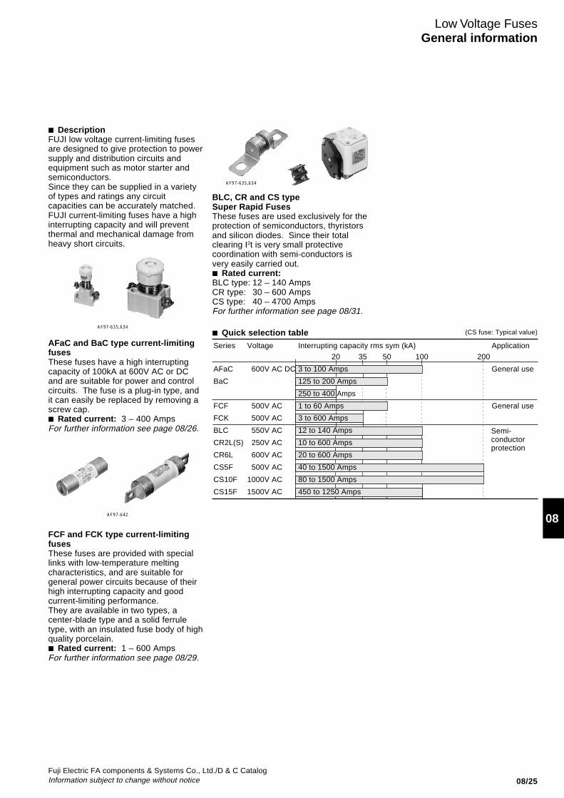
Low Voltage FusesGeneral information
AFaC and BaC type current-limitingfusesThese fuses have a high interruptingcapacity of 100kA at 600V AC or DCand are suitable for power and controlcircuits. The fuse is a plug-in type, andit can easily be replaced by removing ascrew cap.■ Rated current: 3 – 400 AmpsFor further information see page 08/26.
FCF and FCK type current-limitingfusesThese fuses are provided with speciallinks with low-temperature meltingcharacteristics, and are suitable forgeneral power circuits because of theirhigh interrupting capacity and goodcurrent-limiting performance.They are available in two types, acenter-blade type and a solid ferruletype, with an insulated fuse body of highquality porcelain.■ Rated current: 1 – 600 AmpsFor further information see page 08/29.
■ DescriptionFUJI low voltage current-limiting fusesare designed to give protection to powersupply and distribution circuits andequipment such as motor starter andsemiconductors.Since they can be supplied in a varietyof types and ratings any circuitcapacities can be accurately matched.FUJI current-limiting fuses have a highinterrupting capacity and will preventthermal and mechanical damage fromheavy short circuits.
20 35 50 100 200
Semi-conductorprotection
BLC, CR and CS typeSuper Rapid FusesThese fuses are used exclusively for theprotection of semiconductors, thyristorsand silicon diodes. Since their totalclearing I2t is very small protectivecoordination with semi-conductors isvery easily carried out.■ Rated current:BLC type: 12 – 140 AmpsCR type: 30 – 600 AmpsCS type: 40 – 4700 AmpsFor further information see page 08/31.
(CS fuse: Typical value)AF97-635,634
AF97-642
AF97-635,634
■ Quick selection tableSeries Voltage Interrupting capacity rms sym (kA) Application
AFaC 600V AC DC 3 to 100 Amps General use
BaC 125 to 200 Amps
250 to 400 Amps
FCF 500V AC 1 to 60 Amps General use
FCK 500V AC 3 to 600 Amps
BLC 550V AC 12 to 140 Amps
CR2L(S) 250V AC 10 to 600 Amps
CR6L 600V AC 20 to 600 Amps
CS5F 500V AC 40 to 1500 Amps
CS10F 1000V AC 80 to 1500 Amps
CS15F 1500V AC 450 to 1250 Amps

08/26Fuji Electric FA components & Systems Co., Ltd./D & C Catalog
Information subject to change without notice
AFaC and BaC type current-limiting fuses600V AC/DC, 3–400 Amps■ DescriptionThe AFaC and BaC type have anexcellent current-limiting performancewith an interrupting capacity as high as100kA at 600V AC/DC. They aresuitable for power circuits and controlcircuit applications including generalpower cubicles, distribution equipment,motor starters, load centers and controlcenters. The fuse assembly comprisesbase, screw cap, fuse link and adapterring. The universal surface mountingterminals are provided with screwswhile the rear connection type aresupplied with stud bolts. The fuse linkcan easily and safely be replaced bysimply removing a screw cap.The diameter of the solid ferrule fuselink varies according to the ratedcurrent. The higher the rating, thegreater the diameter.As a safety feature the screw cap canonly be tightened when the fuse linkmatches with the adapter ring locatedinside the base. This prevents the capfrom being tightened even when fuse
Low Voltage FusesAFaC and BaC types
AF97-634 O-1299
AFaC-60 BaC-100 60A 200ARear connection type Surface connection type
link with larger ratings is inserted. Theoperating blown indication tip can beobserved through the screw capwindow. The tip color indicates thecurrent rating – for instance, pinkindicates 3A and red 10A. The tip isejected to show that the fuse hasblown. Both the base and the screwcap are made from a high class
porcelain insulating material to ensuretrouble-free operation. The fuse canbe replaced without isolating the circuit.Since the fuse link is housed in a highlyreliable porcelain barrel it is strongmechanically and thermally with nodanger of explosion or production ofnoxious gases when blown.
■ Components of AFaC and BaC type
Parts
Rated Fuse-link Screw cap Base Adapter ringcurrent Surface connection Rear connection Color of(A) Type Color of indicator Type Type Type Type adapter ring
3 BLA003 Pink Pa30 AFa30 Ba30 R3 Pink 5 BLA005 Brown R5 Brown 10 BLA010 Red R10 Red 15 BLA015 Gray R15 Gray 20 BLA020 Blue R20 Blue 30 BLA030 Violet — —
40 BLA040 Black Pa60 AFa60 Ba60 R40 Black 60 BLA060 Light red — —
75 BLA075 Silver Pa100 AFa100 Ba100 R75 Silver100 BLA100 Red — —
125 BLA125 Yellow Pa200 AFa200 Ba200 R125 Yellow150 BLA150 Light red R150 Light red200 BLA200 Blue — —
250 BLA250 Green Pa400 AFa400 Ba400 R250 Green300 BLA300 White R300 White400 BLA400 Black — —
FA776 SD-39 SD-39 SDO 0091M SD-63
Minimum ordering quantity• Fuse-link BLA003 to 030 100 pcs. • Base AFa30 Ba30 100 pcs.
BLA 040, 060 20 AFa60 Ba60 50BLA 075 to 200 10 AFa100 Ba100 10BLA 250 to 400 5 AFa200 Ba200 5
AFa400 Ba400 1
• Screw cap Pa30 100 pcs. • Adapter ring R3 to 20, R75 100 pcs.Pa60 50 R40, R125 to 300 50Pa100 10Pa200 5Pa400 1
Thickness of mounting plate: 3.2mm or less
IndicatingwinndowScrew cap
Faucet screw
Fuse-Iink
Terminal (load)
Terminal (Iine)
Adapter ring
Contact spring
Beae
Base
Cap Insulating plate
Mounting plate
Front bushing
Rear bushing

Fuji Electric FA components & Systems Co., Ltd./D & C CatalogInformation subject to change without notice 08/27
08
■ Specifications
Fuse-link Rated Rated Interrupting Max. interruptingType current voltage capacity I 2 t
(A) (kA) (Amp2 x sec.)
BLA003 3 600V AC 100 28BLA005 5 DC 110BLA010 10 500
BLA015 15 100 750BLA020 20 1.3 × 10³
BLA030 30 5 × 10³
BLA040 40 100 9.2 × 10³
BLA060 60 27 × 103
BLA075 75 100 70 × 103
BLA100 100 100 × 103
BLA125 125 50 290 × 103
BLA150 150 390 × 103
BLA200 200 500 × 103
BLA250 250 20 1800 × 103
BLA300 300 2200 × 103
BLA400 400 3000 × 103
■ Characteristic curvesMelting time-current characteristic Permissible time-current characteristic Current-limiting characteristic
■ Ordering informationSpecify the following:1. Type number
Fuse-link BaseBLA 003 AFa 30
Rated current Frame sizeEx. 003 : 3 Amps 30: For 3 to 30A
075 : 75 Amps 60: For 40, 60A200 : 200 Amps 100: For 75, 100A
Fuse-link 200: For 125, 150, 200A400: For 250, 300, 400A
ConnectionAFa: SurfaceBa : RearScrew cap
Pa 30
Frame size 30: For 3 to 30A 60: For 40, 60A100: For 75, 100A200: For 125, 150, 200A400: For 250, 300, 400A
Screw cap
■ Mounting on steel panelTo mount a rear connection base Ba on a steel panel, aninsulting plate and some bushings are used. Kits for 30, 60,100, 200 and 400A base are available. Please specify yourbase type when ordering.Two front bushings are used with 100, 200 and 400A baseonly.Example: Insulating plate and bushings for Ba30
■ Tightening toolIt is recommended that fuses with ratings of over 100A betightened with a special tool since there is the possibility ofoverheating if the screw cap is not adequately tightened.This exclusive use tool is sold separately.
Type Screw cap type
Pa100H Pa100Pa200H Pa200Pa400H Pa400
Low Voltage FusesAFaC and BaC types
AF90-316
AF97-644
Min
ute
Sec
ond
Sec
ondTim
e
Current (A) Available current (Sym, rms) I eff. (kA)
Min
ute
Max
. Le
t-th
roug
h cu
rren
t (P
eak
valu
e) k
A
Tim
e
Current (A)

08/28Fuji Electric FA components & Systems Co., Ltd./D & C Catalog
Information subject to change without notice
■ Dimensions, mm● Fuse-link
Type Rated A B øD ød Masscurrent (A) (g)
BLA003 3 50 10 13 8 12BLA005 5 50 10 13 8 12BLA010 10 50 10 13 8 12BLA015 15 50 10 13 10 12BLA020 20 50 10 13 10 12BLA030 30 50 10 13 14 12
BLA040 40 50 10 27 16 47BLA060 60 50 10 27 20 62
BLA075 75 63 5.4 34 5 120BLA100 100 63 5.4 34 8 120
BLA125 125 63 5.4 47 5 215BLA150 150 63 5.4 47 8 215BLA200 200 63 5.4 47 10 215
BLA250 250 63 5.4 61 5 380BLA300 300 63 5.4 61 8 380BLA400 400 63 5.4 61 10 380
3 to 30A 40 to 60A 75 to 400A
Low Voltage FusesAFaC and BaC types
Type A B C D E F G H K øL Mass(max.) (max.) (max.) (max.) (g)
BaC-3 to 30 47 47 52 62 10 14 78.5 M5 32 6(14) 220BaC-40 to 60 66 66 54 65 18 22.5 87.5 M6 47 7(14) 470BaC-75 to 100 85.5 85.5 71 70 22 30 112.5 M8 72 9(25) 1200BaC-125 to 200 112 112 78 75 28 39 120 M10 87 11(25) 2115
( ): In the casethe steel plateis used.
● Base and capSurface connectionAFaC-3 to 200
Rear connection Panel drillingBaC-3 to 200
Surface connection Rear connectionAFaC-250 to 400 BaC-250 to 400Mass: 4.37kg Mass: 4.76kg
Type A B B1 C D D1 øE G H K L M M1 Y1 Y2 Mass(max.) (max.) (g)
AFaC-3 to 30 34 42 55 46.5 24 22 5 78.5 10 32 M5 18 24 22 22 100AFaC-40 to 60 52 59 82 51 34 38 5.5 88 10 47 M6 21 26 33 33.5 290AFaC-75 to 100 67 87 125 71 40 64 7 118 28 72 M8 27.5 29.5 50 50 950AFaC-125 to 200 77 107 150 73 51 82 7 120 28 87 M10 34 35 60 59.5 1465
øDB
ød
A
ød
B
A
øDøD
Position of indicator
A
ød
BC
Y1
L (Load)
M1
H
BB1
L (Line)
M
G
K
Y2
D1
AD
E
D1
D
Panel drilling
L
F
(2-ø14)
EF
B
A
K
GC
D
EH
Load Line
45˚
45˚
4-M6
70
160
M12×30
140
51
103
83 139.
5 m
ax
15
209 max
Mounting hole 4-7ø
70
117
max
160102 max
140
( ) :In the case the steel plate is used
(2-ø26)2-PF1/4
117
max
209 max102 max
140
103
83 139.
5 m
ax90
PF1/4(ø13)
Panel drillingPanel drilling

Fuji Electric FA components & Systems Co., Ltd./D & C CatalogInformation subject to change without notice 08/29
08
FCF, FCK type current-limiting fuses500V ACFCF Up to 60 AmpsFCK Up to 600 Amps
■ DescriptionFCF and FCK HRC fuses use aspecially designed low-temperaturemelting element, a feature of 'dualelement' fuses. There is no fusedeterioration due to overcurrentphenomena such as rush current at thetime of motor starting and they alsofeature time-lag operationcharacteristics. They operate rapidlyand positively in the face of destructiveshort circuit currents. Since they arecurrent-limiting fuses with a highcapacity of 50kA (FCF types: 1 – 60Amps) they are suitable for many typesof power and control circuits. The fuselink is housed in a ceramic barrel with
excellent thermal and mechanicalcharacteristics and is packed in silicasand which prevents arcing. Thusthere are no fears of explosion orproduction of noxious gases. TheFCF's link end is a solid ferrule-typeand available in 1 – 60 Amps ratings.The FCK is a center blade-type andavailable in 3 – 600 Amps ratings.The fuse links for the 75 Amps FCKand larger sizes are provided with ablown fuse indicator.
SD-240
■ Ordering informationSpecify the following:1. Type number
FCF series
Rated Interrupting Fuse-linkcurrent capacity(A) (kA) Type
1 50 FCF2-1 3 FCF2-3 5 FCF2-510 FCF2-1015 FCF2-1520 FCF2-2030 FCF2-3040 FCF2-4050 FCF2-5060 FCF2-60
Note: Minimum ordering quantityFuse-link: 100 pcs.
T-7
FCK series
Rated Interrupting Fuse-linkcurrent capacity(A) (kA) Type
3 35 FCK2-3 5 FCK2-5 10 FCK2-10 15 FCK2-15 20 FCK2-20 30 FCK2-30
40 FCK2-40 50 FCK2-50 60 FCK2-60
75 FCK2-75100 FCK2-100
125 FCK2-125150 FCK2-150200 FCK2-200250 FCK2-250300 FCK2-300400 FCK2-400500 FCK2-500600 FCK2-600
Note: Minimum ordering quantityFuse-link: 100 pcs.
■ Dimensions, mm● Fuse-linkFCF2-1 to 30 FCF2-40 to 60
● Fuse-linkFCK2-3 to 600
Low Voltage FusesFCF and FCK types
FCF series fuse-link FCK series fuse-link Blown fuse indicator
Type A B C D E Mass (g)
FCK2-3 to 30 50 15 ø19.8 13 66.5 35FCK2-40 to 60 75 19 ø24.9 16 96 95FCK2-75, 100 95 25 ø31 20 122.5 180FCK2-125 to 200 110 35 ø45 30 148.5 470FCK2-250 to 400 120 50 ø63 40 170 1100FCK2-500, 600 145 60 ø75 50 205 2000
16.5
75
ø20
16.513.5
50
ø15
13.5
B A B
D
E C
Mass: 20g Mass: 80g
AF97-643

08/30Fuji Electric FA components & Systems Co., Ltd./D & C Catalog
Information subject to change without notice
Min
ute
Sec
ond
Tim
e
Current (A)
■ Characteristic curves● FCF typeMelting time-current characteristic
● FCK typeMelting time-current characteristic
Permissible time-current characteristic Permissible time-current characteristic
Current limiting characterisitc Current limiting characterisitc
Low Voltage FusesFCF and FCK types
Min
ute
Sec
ond
Tim
e
Current (A)
Max
. Le
t-th
roug
h cu
rren
t (P
eak
valu
e) k
A
Available current (Sym, rms) I eff. (kA)
Min
ute
Sec
ond
Tim
eCurrent (A)
Sec
ond
Min
ute
Tim
e
Current (A)
Max
. Le
t-th
roug
h cu
rren
t (P
eak
valu
e) k
A
Available current (Sym, rms) I eff. (kA)

Fuji Electric FA components & Systems Co., Ltd./D & C CatalogInformation subject to change without notice 08/31
08
■ SpecificationsRated Rated Peak Max. Watt Fuse-linkcurrent voltage arc interrupting I2t loss
voltage (Amp2×sec.)× 103 Type
(A) (V) (W) 12 550V 1550 0.09 5.1 BLC012-1 20 AC 1550 0.27 8.5 BLC020-1 23 1550 0.39 10 BLC023-1 45 1380 1.8 19 BLC045-1 75 1250 5 32 BLC075-1 90 1250 11.5 38 BLC090-1120 1200 33 51 BLC120-1140 1200 100 59 BLC140-1 30 250V Max. 0.35 4.0 CR2L-30 50 AC 500 0.85 6.0 CR2L-50 75 2.3 9.0 CR2L-75100 4.0 12.0 CR2L-100125 6.5 14.0 CR2L-125140 7.0 16.0 CR2L-140150 9.5 18.0 CR2L-150175 13 21.0 CR2L-175200 17 23.0 CR2L-200225 22 26.0 CR2L-225260 27 30.0 CR2L-260300 38 35.0 CR2L-300325 49 37.0 CR2L-325350 60 37.0 CR2L-350400 103 39.0 CR2L-400450 140 46.0 CR2L-450500 160 48.0 CR2L-500550 200 51.0 CR2L-550600 215 56.0 CR2L-600
Interrupting capacityBLC ...... 100kA at 550V ACCR2L .... 100kA at 250V AC
BLC, CR and CS typesSuper Rapid Fuses150–1500 Volts AC10–4700 Amps
■ DescriptionThe FUJI BLC, CR and CS types areextremely reliable fuses which havebeen specially developed to provideprotection for silicon diodes andthyristors and are suitable for invertersusing semiconductors or transformers-rectifiers. FUJI Super Rapid Fuses aredesigned with a very small total I2tvalue which gives them a high speedinterrupting action in the face ofabnormal currents.In addition the arc voltage generated atthe time of interruption has a low valueso that faults will not influence relatedelectric machinery and equipment.These fuses can carry out theprotection of many types of circuitsrating from the semiconductorovercurrents to destructive short-circuiting faults-i.e. when the
SD-36 SM-388 SI-431 SI-429
BLC CR2L CS5F CS10F
semiconductors short or circuits fail thesound elements will be quickly isolatedfrom the fault circuits.
■ Features• The total clearing I2t is small and the
semiconductor circuit is completelyprotected.
• Since the peak arc voltage at thetime of interruption is low damage toother equipment does not occur.
Low Voltage FusesBLC, CR and CS types
Super Rapid Fuses
Rated Rated Peak Max. Watt Fuse-linkcurrent voltage arc interrupting I2t loss
voltage (Amp2×sec.)× 103 Type
(A) (V) (W) 10 250V Max. 0.04 1.2 CR2LS-10 20 AC 500 0.17 3.0 CR2LS-20 30 0.35 4.0 CR2LS-30 50 0.85 6.0 CR2LS-50 75 2.3 9.0 CR2LS-75100 4.0 12.0 CR2LS-100 20 600V Max. 0.14 4.0 CR6L-20 30 AC 1200 0.35 7.0 CR6L-30 50 1.8 9.0 CR6L-50 75 3.0 12.5 CR6L-75100 7.0 15 CR6L-100
150 18 22.0 CR6L-150200 30 34.0 CR6L-200250 70 37.0 CR6L-250300 95 40.0 CR6L-300350 150 45.0 CR6L-350400 200 55 CR6L-400500 390 60 CR6L-500600 700 70 CR6L-600
Interrupting capacityCR2LS . 100kA at 250V ACCR6L .... 100kA at 600V AC
• High interrupting capacity of 200kAat 1000V AC
• The CS type is provided with a blownfuse indicator. An alarm contactblock (1NO or 1NC) can also beattached.
■ UL recognized: CR2L/UL,CR2LS/UL,CR6L/UL(File No. E92312)CSA certificated: CR2LS/UL(File No. LO4000-4090)TÜV: CR2LS/UL (10-100A),
CR2L/UL (150-350A)(Rep. No. E9450643E02)CR6L/UL (50-300A)(Rep. No. E9560543E02)

08/32Fuji Electric FA components & Systems Co., Ltd./D & C Catalog
Information subject to change without notice
■ Specifications (UL-recognized, CSA certified, TÜV)
Rated Rated Inter- Max. Watt Fuse-linkcurrent voltage rupting interrupting I2t loss
capacity (Amp2×sec.)× 103 Type
(A) (kA) (W) 10 250V AC 10 at AC 0.04 1.2 CR2LS-10/UL 20 400V DC (pf: 0.8) 0.17 3.0 CR2LS-20/UL 30 10 at DC 0.35 4.0 CR2LS-30/UL 50 (L/R: 2ms) 0.85 6.0 CR2LS-50/UL 75 2.3 9.0 CR2LS-75/UL100 4.0 12.0 CR2LS-100/UL
150 9.5 18.0 CR2L-150/UL200 17 23.0 CR2L-200/UL260 27 30.0 CR2L-260/UL350 60 37.0 CR2L-350/UL400 103 39.0 CR2L-400/UL450 140 46.0 CR2L-450/UL500 160 48.0 CR2L-500/UL550 200 51.0 CR2L-550/UL600 215 56.0 CR2L-600/UL 20 600V AC 100 at AC 0.14 4.0 CR6L-20/UL
680V DC (pf: 0.8) 30 10 at DC 0.35 7.0 CR6L-30/UL
(L/R: 2ms) 50 1.8 9.0 CR6L-50/UL 75 3.0 12.5 CR6L-75/UL100 7.0 15.0 CR6L-100/UL150 100 at AC 18 22.0 CR6L-150/UL
(pf: 0.8)200 50 at DC 30 34.0 CR6L-200/UL
(L/R: 2ms)300 95 40.0 CR6L-300/UL
■ Specifications
Rated Inter- Max. Watt Fuse-linkcurrent rupting interrupting I2t loss
capacity (Amp2×sec.)× 103 Type
(A) (kA) (W)4700 150 at 14000 310 CS1F-4700
125V AC2000 150 at 1950 124 CS2F-20003000 250V AC 5500 216 CS2F-3000 40 200 at 1 6.4 CS5F-40 75 500V AC 3.5 12 CS5F-75 100 5 17 CS5F-100 150 10 25 CS5F-150 200 18.5 34 CS5F-200 250 33 42 CS5F-250 300 64 45 CS5F-300 350 85 56 CS5F-350 400 122 57 CS5F-400 450 131 62 CS5F-450 500 159 73 CS5F-500 600 257 80 CS5F-600 800 600 114 CS5F-8001000 1200 110 CS5F-10001000 843 167 CS5F-1000-P1200 1800 114 CS5F-12001200 1311 200 CS5F-1200-P1500 3600 209 CS5F-15001000 200 at 1800 125 CS8F-10001200 800V AC 2500 176 CS8F-12001500 4400 220 CS8F-1500 80 200 at 10 17 CS10F-80 100 1000V AC 16 21 CS10F-100 150 37 27 CS10F-150 200 63 37 CS10F-200 250 110 44 CS10F-250 300 148 53 CS10F-300 350 211 70 CS10F-350 400 307 74 CS10F-400 500 420 90 CS10F-500 560 410 102 CS10F-560 630 450 135 CS10F-630 750 640 156 CS10F-750 800 1259 211 CS10F-800-P1000 1722 245 CS10F-1000-P1250 2250 330 CS10F-1250-P1500 3200 334 CS10F-1500-C 450 100 at 350 134 CS15F-450 630 1500V AC 760 170 CS15F-630 900 1400 280 CS15F-900-P1250 3050 350 CS15F-1250-P
Note: • Peak arc voltageCS1F ..... Max. 450VCS2F ..... Max. 750VCS5F ..... Max. 1000VCS8F ..... Max. 2000VCS10F ... Max. 2000VCS15F ... Less than 3000V
• An alarm contact block AHX2905 (1NO) or AHX2915 (1NC) can beattached to CS type. (Sold separately) See page 08/40.
Low Voltage FusesBLC, CR and CS typesSuper Rapid Fuses
Note: • Peak arc voltageCR2LS, CR2L .... Max. 500VCR6L .................. Max. 1200V
• The peak arc voltage is obtained by interruption caused by the listedinterrupting current at rated voltage.
• This indcates the values when the conductors specified in ULStandards are connected and rated current apply.
• TÜV: CR2LS, 2L: Up to 350A CR6L: 50 to 300A
Note: UL recognized fuseIn the UL recognized fuses, a fuse with a blown inidcation fuse, or afuse both with a blown indication fuse and a precision switch is alsoUL recognized.Examples: CR2L-200G/UL
CR2LS-30S/ULCR6L-100G/UL
■ CR type fuse with optional accessoryFuse with blown indication fuseCR2L (S)- G
AF88-446
Fuse with blown indication fuse and precision switchCR2L (S)- S Precision switch (SPDT)
CRX-1
AF88-445 AF88-442
precision switch
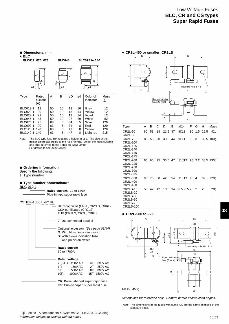
Fuji Electric FA components & Systems Co., Ltd./D & C CatalogInformation subject to change without notice 08/33
08
■ Dimensions, mm● BLC
BLC012, 020, 023 BLC045 BLC075 to 140
Type Rated A B øD ød Color of Masscurrent indicator (g)(A)
BLC012-1 12 50 10 13 10 Grey 12BLC020-1 20 50 10 13 14 Yellow 12BLC023-1 23 50 10 13 14 Violet 12BLC045-1 45 50 10 27 20 White 62BLC075-1 75 63 6 34 5 Silver 120BLC090-1 90 63 6 34 8 Red 120BLC120-1 120 63 6 47 8 Yellow 120BLC140-1 140 63 6 47 8 Light red 215
Note: The BLC type fuse link requires a holder in use. The size of theholder differs according to the fuse ratings. Select the most suitableone after referring to the Table on page 08/40.For drawings see page 08/28.
● CR2L-450 or smaller, CR2LS
Low Voltage FusesBLC, CR and CS types
Super Rapid Fuses
Dimensions for reference only. Confirm before construction begins.
Type A B C D E a×b F G H Mass
CR2L-30 80 58 18 21.5 37 9×11 90 1.5 26.5 42gCR2L-50CR2L-75 80 58 20 30.5 44 9×11 90 3 32.5 100gCR2L-100CR2L-125CR2L-140CR2L-150CR2L-175CR2L-200 85 60 25 33.5 47 11×13 93 3.2 33.5 130gCR2L-225CR2L-260CR2L-300CR2L-325CR2L-350 95 70 30 42 54 11×13 98 4 39 220gCR2L-400CR2L-450CR2LS-10 56 42 12 18.5 34.5 6.5×8.5 78 2 25 28gCR2LS-20CR2LS-30CR2LS-50CR2LS-75CR2LS-100
Note: The dimensions of the fuses with suffix. UL are the same as those of thestandard ones.
■ Ordering informationSpecify the following:1. Type number
■ Type number nomenclatureBLC 012-1
Rated current: 12 to 140APlug-in type super rapid fuse
CS 10F-1000 -P/ ULUL recognized (CR2L, CR2LS, CR6L)CSA certificated (CR2LS)TÜV (CR2LS, CR2L, CR6L)
2-fuse connected parallel
Optional accessory (See page 08/44)G: With blown indication fuseS: With blown indication fuse
and precision switch
Rated current10 to 4700A
Rated voltage2L, 2LS: 250V AC, 6L: 600V AC1F: 150V AC, 2F: 250V AC5F: 500V AC, 8F: 800V AC10F: 1000V AC, 15F: 1500V AC
CR: Barrel-shaped super rapid fuseCS: Cubic-shaped super rapid fuse
Mass: 450g
● CR2L-500 to -600
øD
B
ød
A
ød
B
A
øDøD A
ød
B
Blown indicatinfuae (G type)
Mounting hole a × b
B
H
E
D
C
F
A
G
ø37
46.5
Blown indicationfuse (G type)
70
31
41.543
46
28
54
84
30
98
84
95
8
Mounting hole 11×13

08/34Fuji Electric FA components & Systems Co., Ltd./D & C Catalog
Information subject to change without notice
■ Dimensions, mm● CR6L-20, CR6L-30, CR6L-50 ● CR6L-75 to 300 ● CR6L-350 to 600
Type A B C D E F G H a×b Mass (g)
CR6L-75 95 70 25 34 47 102 3.2 33.5 11×13 150CR6L-100CR6L-150
CR6L-200 107 82 30 42 54 107 4 39 11×13 246CR6L-250CR6L-300
Type A B C D Mass (g)
CR6L-350 107 82 43 107 493
CR6L-400 121 96 43 114 522CR6L-500
CR6L-600 121 96 47.4 114 545
● CS1F-4700CS2F-2000, 3000
● CS5F-40 to 1500CS10F-80 to 750CS15F-450, 630
● CS8F-1000, 1200, 1500
Voltage Type A B C D M Mass(Max.) (g)
500V CS5F-40 47 47 42.5 65.5 M8 320CS5F-75CS5F-100CS5F-150CS5F-200
CS5F-250 57 51 47 70 M8 510CS5F-300CS5F-350
CS5F-400 72 51 54.5 77 M10 800CS5F-450CS5F-500CS5F-600CS5F-800
CS5F-1000 72 51 54.5 77 M12 830CS5F-1200CS5F-1500
Voltage Type A B C D M Mass(Max.) (g)
800V CS8F-1000 72 74 54.5 84 M12 1060CS8F-1200
CS8F-1500 72 82 54.5 84 M8 1150
1000V CS10F-80 47 71 42.5 65.5 M8 420CS10F-100
CS10F-150 57 74 47 70 M8 690CS10F-200CS10F-250
CS10F-300 72 74 54.5 77 M10 1060CS10F-350CS10F-400CS10F-500CS10F-630CS10F-750
1500V CS15F-450 72 105 54.7 77 M10 1400CS15F-630
Mass: 42g
Low Voltage FusesBLC, CR and CS typesSuper Rapid Fuses
34.5
18
Blown indicationfuse (G type)
Mountng hole 6.5×8.523.5
18.5ø
17.5
25
62
47
27
12
88
74
76
2
E
Blown indicationfuse (G type)
Mountng hole a × b
H
D
B
CG
F
A
84
28
41.54346
46.5 30
B
ø37
54
Mountng hole 11×13
8
D
CA
Blown indicationfuse (G type)
Blown fuse indicator
Alarm contact block AHX2905(NO)AHX2915(NC)
2-MIO72 51
72 30
54
.57
84
ma
x.
M
A B
Alarm contat blockBlown fuse indicator
N.P.
A
C
D7
7
A
7C
30A
M
Blown fuse indicator
Alarm contact block
D
B
Mass: 800g

Fuji Electric FA components & Systems Co., Ltd./D & C CatalogInformation subject to change without notice 08/35
08
■ Dimensions, mm
● CS5F-P CS10F-P, CS15F-P
Voltage Type H L Mass (g)
500V CS5F-1000-P 51 69 1900CS5F-1200-P
1000V CS10F-800-P 74 92 2420CS10F-1000-PCS10F-1250-P
1500V CS15F-900-P 105 123 3100CS15F-1250-P
● CS10F-1500-C
Current-limiting characteristic
Mass: 2500g
■ Characteristic curvesBLCMelting time-current characteristic
Operating time-current characteristic
Low Voltage FusesBLC, CR and CS types
Super Rapid Fuses
M10
N.P.
86158
5
754
.5
H L
7m
ax.7
7
ø1572
4072
Alarm contat block
108107
89.5
M10 M10max.777
7
74 99
5
M10
Alarm contat block
ø15 72
72
40
Tim
e
Min
ute
Sec
ond
Current (A)
Tim
e
Sec
ond
Min
ute
Current (A)
Max
. Le
t-th
roug
h cu
rren
t (P
eak
valu
e) k
A
Available current (Sym, rms) I eff. (kA)

08/36Fuji Electric FA components & Systems Co., Ltd./D & C Catalog
Information subject to change without notice
■ Characteristic curvesCR2L, CR2LSMelting time-current characteristic
Operating time-current characteristic
Current-limiting characteristic
CR6LMelting time-current characteristic
Operating time-current characteristic
Current-limiting characteristic
Low Voltage FusesBLC, CR and CS typesSuper Rapid Fuses
Min
ute
Tim
e
Current (A)
Min
ute
Tim
e
Current (A)
Max
. Le
t-th
roug
h cu
rren
t (P
eak
valu
e) k
A
Available current (Sym, rms) I eff. (kA)
Tim
e
Min
ute
Sec
ond
Current (A)
Tim
e
Min
ute
Sec
ond
Current (A)
Max
. Le
t-th
roug
h cu
rren
t (P
eak
valu
e) k
A
Available current (Sym, rms) I eff. (kA)
Sec
ond
Sec
ond
CR
6L-2
0
CR
6L-3
0
CR
6L-5
0C
R6L
-75
CR
6L-1
00
CR
6L-1
50
CR
6L-2
00C
R6L
-250
CR
6L-3
00
CR
6L-6
00
CR
6L-3
50C
R6L
-400
CR
6L-5
00
CR
6L-2
0C
R6L
-20
CR
6L-2
0
CR
6L-3
0
CR
6L-5
0C
R6L
-75
CR
6L-1
00
CR
6L-1
50
CR
6L-2
00C
R6L
-250
CR
6L-3
00
CR
6L-6
00
CR
6L-3
50C
R6L
-400
CR
6L-5
00
CR
6L-2
0

Fuji Electric FA components & Systems Co., Ltd./D & C CatalogInformation subject to change without notice 08/37
08
■ Characteristic curvesCS1FMelting time-current characteristic
CS2FMelting time-current characteristic
Operating time-current characteristic Operating time-current characteristic
Current-limiting characteristic Current-limiting characteristic
Low Voltage FusesBLC, CR and CS types
Super Rapid Fuses
Min
ute
Sec
ond
Tim
e
Current ( × 103A)
Sec
ond
Min
ute
Tim
e
Current ( × 103A)
Max
. Le
t-th
roug
h cu
rren
t (P
eak
valu
e) k
A
Available current (Sym, rms) I eff. (kA)
Current ( × 103A)
Tim
e
Min
ute
Sec
ond
Tim
e
Min
ute
Sec
ond
Current ( × 103A)
Max
. Le
t-th
roug
h cu
rren
t (P
eak
valu
e) k
A
Available current (Sym, rms) I eff. (kA)

08/38Fuji Electric FA components & Systems Co., Ltd./D & C Catalog
Information subject to change without notice
■ Characteristic curvesCS5FMelting time-current characteristic
CS8FMelting time-current characteristic
Operating time-current characteristic Operating time-current characteristic
Current-limiting characteristic Current-limiting characteristic
Low Voltage FusesBLC, CR and CS typesSuper Rapid Fuses
Min
ute
Tim
eCurrent ( × 103A)
Min
ute
Tim
e
Current ( × 103A)
Max
. Le
t-th
roug
h cu
rren
t (P
eak
valu
e) k
A
Available current (Sym, rms) I eff. (kA)
Tim
e
Min
ute
Sec
ond
Current ( × 10A)
Tim
e
Min
ute
Sec
ond
Current ( × 10A)
Max
. Le
t-th
roug
h cu
rren
t (P
eak
valu
e) k
A
Available current (Sym, rms) I eff. (kA)
Sec
ond
Sec
ond

Fuji Electric FA components & Systems Co., Ltd./D & C CatalogInformation subject to change without notice 08/39
08
■ Characteristic curvesCS10FMelting time-current characteristic
CS15FMelting time-current characteristic
Operating time-current characteristic Operating time-current characteristic
Current-limiting characteristic Current-limiting characteristic
Low Voltage FusesBLC, CR and CS types
Super Rapid Fuses
Min
ute
Tim
e
Sec
ond
Current ( × 10A)
Current ( × 10A)
Min
ute
Sec
ond
Tim
e
Max
. Le
t-th
roug
h cu
rren
t (P
eak
valu
e) k
A
Available current (Sym, rms) I eff. (kA)
Max
. Le
t-th
roug
h cu
rren
t (P
eak
valu
e) k
A
Available current (Sym, rms) I eff. (kA)
Min
ute
Sec
ond
Tim
e
Current ( × 103A)
Current ( × 103A)
Min
ute
Sec
ond
Tim
e

08/40Fuji Electric FA components & Systems Co., Ltd./D & C Catalog
Information subject to change without notice
■ Operating indication● Blown fuse indicationFUJI Super Rapid Fuses are availablein BLC, CR and CS types. These typeshave different methods of indicating ablown fuse.● BLC typeA blown fuse is indicated by the colortip on the ferrule of the fuse beingejected as shown in Fig. 1. This can beseen through the window of the fuseholder.● CR typeThis fuse does not have a blownindicator but if a trigger fuse isconnected as shown in Fig. 2 this willprovide the alarm for blown fuse.● CS typeThis fuse is provided with a blown fuseindicator. In this case a pin in thecontact pad is ejected after the fusehas been blown. If electricalconnections for lamps or alarms arerequired fit the contact block (1NO or1NC) to the pad as shown in Fig. 3.
Fig. 1 Fig. 3
Fig. 2
BLC type
CR type
Alarm contact blockAHX2905, 2915
CS 10F with alarmcontact block
■ Alarm contact block ratings
Type Contact Ratedvoltage (V)
AHX2905 1NO 24110220
AHX2915 1NC 440550
Inductive load
Rated operational Ratedcurrent (A) capacity (W)
6 1501.3 1400.45 1000.2 850.15 85
DC
Resistive load
Rated operational Ratedcurrent (A) capacity (W)
6 1502.5 2751 2200.4 1750.3 165
AC
Inductive cosϕ=0.3~1
Rated operational Ratedcurrent (A) capacity (VA)
6 1506 6606 13202.5 11002 1100
■ Fuse holder for BLC type fuseFUJI BLC fuses require specialholders. Select the most suitable onewhich corresponds to the rated currentof the fuse.Dimensions: See page 08/28.
Fuse link Fuse holderBLC Surface connection
Fuse link Rated Base Screw cap Adaptorcurrent Surface Rear ring
connection connectionType (A) Type Type Type Type
BLC012-1 12 AFa30 Ba30 Pa30 R20BLC020-1 20 AFa30 Ba30 Pa30 –BLC023-1 23 AFa30 Ba30 Pa30 –BLC045-1 45 AFa60 Ba60 Pa60 –BLC075-1 75 AFa100 Ba100 Pa100 R75BLC090-1 90 AFa100 Ba100 Pa100 –BLC120-1 120 AFa200 Ba200 Pa200 –BLC140-1 140 AFa200 Ba200 Pa200 –
AF88-446
SH-384
SM-385CS10F
SD-36
SD-36 AF88-439
Low Voltage FusesBLC, CR and CS typesSuper Rapid Fuses
Line
Load
Alarmcircuit
Alarmcircuit
Triggerfuse
R
F

Fuji Electric FA components & Systems Co., Ltd./D & C CatalogInformation subject to change without notice 08/41
08
■ Application and selection guideBLC, CR and CS-type – Super rapidfuseWhen selecting fuses forsemiconductor rectifier circuit protectionthe following conditions must besatisfied.For additional details contact FUJI.
■ Conditions of application1. The rated interrupting current of the
fuse must be greater than theestimated short circuit current of thecircuit.
Available short Rated interruptingcircuit current current of fuseof rectifier circuit
2. The let-thru current value of fusemust be less than the allowable 1/2cycle surge current value.
Semiconductor – 1/2Fuse let-thru cycle allowable surgecurrent value current 10ms (at 50Hz)
3. The total clearing I2t value which thefuse requires to complete interruptionmust be less than the allowable I2tvalue of semiconductor.
Fuse – total Semiconductor – I2tclearing I2t
4. The rated current of the fuse must begreater than the average forwardcurrent of the semiconductor.
Fuse – Semiconductor –rated current average forward current
5. The rated current and voltage of thefuse must be greater than those ofthe rectifier circuit.
Fuse – rated Rectifier circuit –current andcurrent and voltagevoltage
Method of applicationSemiconductor rectifier equipment hasa variety of rectifier circuits. Taking the3-phase bridge rectifier circuit as anexample – Fig. (a) and (b) as shown inthe following.Although the number of fuses used inthe line fuse method (a) is half thenumber used in the element fusemethod (b), the fuses must have alarger current capacity.
Fig. (a)
Line fuse methodIn this method the fuses are connected tothe AC line side.
Fig. (b)
Element fuse methodIn this method the fuses are connected inseries to the semiconductor element.
■ Fuse ratingsWhen selecting fuses various factorssuch as protection, coordination andload, etc. must be considered.However, in this catalog the mainmatters such as voltage, current and I2tonly are explained.
● Rated voltageThe rated voltage of the fuse indicatesthe maximum operational voltage andthis also indicates the root-mean-square value of the AC sinusoidal wavevoltage. Select fuses having a ratedvoltage exceeding the voltage obtainedby the formula shown in the followingtable. (Fig. 1)Do not select current-limiting fuses withrated voltages drastically exceeding therectifier circuit voltage. It is necessaryto consider the arc voltage.
>= >=
>= >=
>= >=
Fig. 1 Rated voltage required by fusesWire connection Wiring diagram Rated voltage of Fuse (VFN rms)type For line fuse For element fuse
Single-phase bridge VFN a · Ea VFN a · Ea
3-phase bridge VFN a · Ea VFN a · Ea
3-phase, double star VFN a · 3 · Ea VFN a · 3 · Ea
Remarks: The 'a' is a coefficient where the regulation of the AC input voltage is taken into account. Thisis a=1.1 in case of voltage regulation ±10%.
Fig. 2 Element current and line currentWire connection Wiring diagram Element fuse method Line fuse methodtype Element current Ia Line current
Single-phase bridge
3-phase bridge
3-phase, double star
<
<=
<=
>
>
Low Voltage FusesBLC, CR and CS types
Super Rapid Fuses
Ea
Ea
Ea
Ia
Ia
Ia
Id
Id
Id
I
I
I
I
Ia = I = d
= 0.707d
Id√_2_
Ia =
= 0.577dI
Id√_3_ I = Id
= 0.816dI
23
I = Ia =
= 0.289dI
Id2√
_3_

08/42Fuji Electric FA components & Systems Co., Ltd./D & C Catalog
Information subject to change without notice
● Rated currentThe current values in fuses in the linefuse system and the element fusesystem are different. Obtain thecorrect current value from the table onpage 08/41 (Fig. 2).When selecting the rated current of afuse choose a fuse having anamperage rating greater than thecurrent which flows in the semi-conductor if the load is continuous anda fixed current.If the current which flows in thesemiconductor is greater than the ratedcurrent of the fuse connect the fuses inparallel. However, in this case, if thenumbers of fuses arranged in parallelare 'n', then the I2t value of the fuse willbe n2·I2t and n2 times the I2t value ofone fuse. This should be taken intoconsideration when protectivecoordination is taken into account.In the case of the circuit where the loadrapidly varies the fuse element willsuffer from mechanical deteriorationand be damaged by thermal stress.In loads of this type the deteriorationcharacteristics of the fuse must beclosely considered.Moreover if the fuse current – timecharacteristics of the fuse selected isless than the overload characteristicsof the semiconductor element thencomplete protection can be obtained.However, if the semiconductor elementhas a large capacity then protectivecooperation is very difficult to arrange.The fuses are used to isolate theshorted semiconductor element circuitfrom sound operating circuits.
■ Total clearing I2tThe total clearing I2t of fuse is a veryimportant factor when considering theprotective coordination of thesemiconductor. This total clearing I2t isthe value where the arcing I2t is addedto the melting I2t. Therefore it isnecessary to satisfy the followingformula.Fuse – total Semiconductorclearing I2t I2tThe total clearing I2t of fuse dependsupon the operational voltage andinterrupting current.Therefore, for this reason if a 500 Voltsfuse is used in a 300 Volts circuit thetotal clearing I2t is reduced by 50–70%.However, the reduction rate variesaccording to the type of fuseconstruction. This must be checkedand confirmed once more.
ExampleI2tAll I2t values are ampere2 seconds.
The I2t data for silicon diodes orthyristor elements are normally given intheir respective catalogs. If the A2Sdata is not given in their catalog obtainthe value in the following manner. Ifprotection is needed for a 250V, 150A(Io) diode having a maximum allowablepeak half sine wave current of 2700A, itis important that the fuse has a total I2tvalue lower than that of the diode.
Calculation
Maximum I2t diode = ( )2 0.0167
= ( )2 0.0167
= 30,400A2 Sec.
From the table (Page 08/38), the fusewith a total I2t nearest to 30,400A2 Sec.is the 260 Ampere fuse (CR 2L-260).
■ Interrupting currentThe rated interrupting current of thefuse must exceed the maximum value(Symmetrical RMS value) of theestimated circuit fault current.
■ Peak arc voltageIn the case of the current-limiting fusean arc voltage (overvoltage) isgenerated at the time of interruptiondue to its fusible element construction.It is necessary to check that this peakarc voltage does not exceed thesemiconductor's maximum (Non-repetitive peak) reverse voltage value.
■ Current limitationSelect a fuse whose let-thru currentvalue does not exceed the allowable1/2 cycle surge current of thesemiconductor. The allowable surgecurrent is the peak value of the currentwhich in case at 50Hz is allowed toflow for 10ms. In the current-limitingfuse the fault must be cleared in theshortest possible time or in the first1/2 cycle.Available current is the current whichwould flow if the fuse were not current-limiting.This would cause damage toequipment. Let-thru current is theactual current allowed to flow by thecurrent limiting action of the fuse. Anumber of let-thru current graphs aregiven in this catalog and example isgiven in the following paragraph. Themethod of reading this graph isprovided for your reference.
How to find a let-thru current– ExampleFuse: 200 Amps 500VAvailable R.M.S symmetrical current:
100,000 Amps
Let-thru peak current (Instantaneous):11,600 Amps
Let-thru R.M.S. current11,600 ÷ 1.7 = 6,800 Amps
This example clearly shows that whilea 100kA (rms, sym) current isavailable, the fuse limits the current let-thru to 6,800 Amperes (rms, sym).
<=
1 Peak2
27002
Low Voltage FusesBLC, CR and CS typesSuper Rapid Fuses
M:Melting timeA :Arcing timeT :Total clearing time
105,000
100,000AAvailable RMS symmetrical current(Ampere)
Let-thru
Available
Let-
thru
pea
k cu
rren
t(A
mpe
res)
-Pea
k
11,600 200A
Peak let-thru current(Actual short-circuit current)
TimeC
urre
nt
M
T
A
Peak current of first half cycleof available peak current(AC component)
Short circuit current thatwould pass without current-limiting fuse.
DC component
Availa
bleins
tant
aneo
uspe
akcu
rrent
Pf=1
Catalog DisclaimerThe information contained in this catalog does not constitute an express or implied warranty of quality, any warranty of merchantability of fitness for a particular purpose is hereby disclaimed.
Since the user's product information, specific use application, and conditions of use are all outside of Fuji Electric FA Components & Systems'control, it shall be the responsibility of the user to determine the suitability of any of the products mentioned for the user's application.
One Year Limited WarrantyThe products identified in this catalog shall be sold pursuant to the terms and conditions identified in the"Conditions of Sale" issued by Fuji Electric FA with each order confirmation.
Except to the extent otherwise provided for in the Conditions of Sale issued by Fuji Electric FA, Fuji Electric FA warrants that the Fuji Electric FA products identified in this catalog shall be free from significant defects in materials and workmanship provided the product has not been: 1) repaired or altered by others than Fuji Electric FA; 2) subjected to negligence, accident, misuse, or damage by circumstances beyond Fuji Electric FA's control; 3) improperly operated, maintained or stored; or 4) used in other than normal use or service. This warranty shall apply only to defects appearing within one (1) year from the date of shipment by Fuji Electric FA, and in such case, only if such defects are reported to Fuji Electric FA within thirty (30) days of discovery by purchaser. Such notice should be submitted in writing to Fuji Electric FA at 5-7, Nihonbashi Odemma-cho, Chuo-ku, Tokyo, Japan. The sole and exclusive remedy with respected to the above warranty whether such claim is based on warranty, contract, negligence, strict liability or any other theory, is limited to the repair or replacement of such product or, at Fuji Electric FA's option reimbursement by Fuji Electric FA of the purchase price paid to Fuji Electric FA for the particular product. Fuji Electric FA does not make any other representations or warranties, whether oral or in writing, expressed or implied, including but not limited to any warranty regarding merchantability or fitness for a particular purpose. Except as provided in the Conditions of Sale, no agent or representative of Fuji Electric FA is authorized to modify the terms of this warranty in writing or orally. In no event shall Fuji Electric FA be liable for special, indirect or consequential damages, including but not limited to, loss of use of the product, other equipment, plant and power system which is installed with the product, loss of profits or revenues, cost of capital, or claims against the purchaser or user of the product by its customers resulting from the use of information, recommendations and descriptions contained herein. The purchaser agrees to pass on to its customers and users, in writing at the time inquiries and orders are received by buyer, Fuji Electric FA's warranty as set forth above.
Caution "Safety precautions"• Operate (keep) in the environment specified in the operating instructions and manual. High temperature, high
humidity, condensation, dust, corrosive gases, oil, organic solvents, excessive vibration or shock might cause electric shock, fire, erratic operation or failure.
• Follow the regulations of industrial wastes when the product is to be discarded.• The products covered in this catalogs have not been designed or manufactured for use in equipment or systems
which, in the event of failure, can lead to loss of human life.• If you intend to use the products covered in this catalog for special applications, such as for nuclear energy control,
aerospace, medical, or transportation, please consult our Fuji Electric FA agent.• Be sure to provide protective measures when using the product covered in these catalogs in equipment which, in the
event of failure, may lead to loss of human life or other grave results.• Follow the directions of the operating instructions when mounting the product.

Information in this catalog is subject to change without notice.
5-7, Nihonbashi Odemma-cho, Chuo-ku, Tokyo, 103-0011, Japan URL http://www.fujielectric.co.jp/fcs/eng
IND
IVID
UA
L CA
TA
LOG
from
D&
C C
AT
ALO
G 20th E
ditio
n
08
LOW VOLTAGE PRODUCTS Up to 600 VoltsIndividualcatalog No.
01 Magnetic Contactors and StartersThermal Overload Relays, Solid-state Contactors
02
Industrial Relays, Industrial Control RelaysAnnunciator Relay Unit, Time Delay Relays
Manual Motor Starters and Contactors Combination Starters
Pushbuttons, Selector Switches, Pilot LightsRotary Switches, Cam Type Selector SwitchesPanel Switches, Terminal Blocks, Testing Terminals
Molded Case Circuit BreakersAir Circuit Breakers
Earth Leakage Circuit BreakersEarth Leakage Protective Relays
Measuring Instruments, Arresters, TransducersPower Factor ControllersPower Monitoring Equipment (F-MPC)
Circuit ProtectorsLow Voltage Current-Limiting Fuses
03
04
05
06
07
08
09
10
HIGH VOLTAGE PRODUCTS Up to 36kV
11Disconnecting Switches, Power FusesAir Load Break SwitchesInstrument Transformers — VT, CT
D&C CATALOG DIGEST INDEX
AC Power RegulatorsNoise Suppression FiltersControl Power Transformers
12 Vacuum Circuit Breakers, Vacuum Magnetic ContactorsProtective Relays
Limit Switches, Proximity SwitchesPhotoelectric Switches
01 02 03 04 05 06 07 08 09 10 11 12
INDIVIDUAL CATALOGfrom D&C CATALOG 20th Edition 08INDIVIDUAL CATALOG
from D&C CATALOG 20th Edition 08
CIRCUIT PROTECTORS
LOW VOLTAGE CURRENT - LIMITING FUSES
CP-P typeCircuit protectors
CP-B typeCircuit protectors
CP-V typeCircuit protectors
AFaC and BaC typesHRC fuses
BLC, CR and CS typesSuper Rapid Fuses
LOWVOLTAGE
EQUIPMENTUp to 600 Volts
CP-F typeCircuit protectors
2010-04 PDF FOLS DEC2008