welded steel tanks for oil storage...1.1.8 appendix b provides recommendations for the design and...
TRANSCRIPT

Copyright American Petroleum Institute Provided by IHS under license with API No reproduction or networking permitted
--``,,,,,,`,,`,`,`,``,,````,,``-`-`,,`,,`,`,,`---
Welded Steel Tanks forOil Storage
API STANDARD 650ELEVENTH EDITION, JUNE 2007
Licensee=Bazan Oil Refineries Ltd/5957352001 Not for Resale, 02/18/2008 23:53:18 MST without license from IHS

Copyright American Petroleum Institute Provided by IHS under license with API Licensee=Bazan Oil Refineries Ltd/5957352001
Not for Resale, 02/18/2008 23:53:18 MSTNo reproduction or networking permitted without license from IHS
--``,,,,,,`,,`,`,`,``,,````,,``-`-`,,`,,`,`,,`---

Copyright American Petroleum Institute Provided by IHS under license with API No reproduction or networking permitted
--``,,,,,,`,,`,`,`,``,,````,,``-`-`,,`,,`,`,,`---
Welded Steel Tanks forOil Storage
Downstream Segment
API STANDARD 650ELEVENTH EDITION, JUNE 2007
Licensee=Bazan Oil Refineries Ltd/5957352001 Not for Resale, 02/18/2008 23:53:18 MST without license from IHS

SPECIAL NOTES
API publications necessarily address problems of a general nature. With respect to particularcircumstances, local, state, and federal laws and regulations should be reviewed.
Neither API nor any of API’s employees, subcontractors, consultants, committees, or otherassignees make any warranty or representation, either express or implied, with respect to theaccuracy, completeness, or usefulness of the information contained herein, or assume anyliability or responsibility for any use, or the results of such use, of any information or processdisclosed in this publication. Neither API nor any of API’s employees, subcontractors, con-sultants, or other assignees represent that use of this publication would not infringe upon pri-vately owned rights.
Classified areas may vary depending on the location, conditions, equipment, and substancesinvolved in any given jurisdiction. Users of this Standard should consult with the appropriateauthorities having jurisdiction.
Users of this Standard should not rely exclusively on the information contained in this docu-ment. Sound business, scientific, engineering, and safety judgment should be used inemploying the information contained herein.
API is not undertaking to meet the duties of employers, manufacturers, or suppliers to warnand properly train and equip their employees, and others exposed, concerning health andsafety risks and precautions, nor undertaking their obligations to comply with authoritieshaving jurisdiction.
Information containing safety and health risks and proper precautions with respect to partic-ular materials and conditions should be obtained from the employer, the manufacturer orsupplier of that material, or the material safety data sheet.
API publications may be used by anyone desiring to do so. Every effort has been made bythe Institute to assure the accuracy and reliability of the data contained in them; however, theInstitute makes no representation, warranty, or guarantee in connection with this publicationand hereby expressly disclaims any liability or responsibility for loss or damage resultingfrom its use or for the violation of any authorities having jurisdiction with which this publi-cation may conflict.
API publications are published to facilitate the broad availability of proven, sound engineer-ing and operating practices. These publications are not intended to obviate the need forapplying sound engineering judgment regarding when and where these publications shouldbe utilized. The formulation and publication of API publications is not intended in any wayto inhibit anyone from using any other practices.
Any manufacturer marking equipment or materials in conformance with the markingrequirements of an API standard is solely responsible for complying with all the applicablerequirements of that standard. API does not represent, warrant, or guarantee that such prod-ucts do in fact conform to the applicable API standard.
07
All rights reserved. No part of this work may be reproduced, stored in a retrieval system, or transmitted by any means, electronic, mechanical, photocopying, recording, or otherwise,
without prior written permission from the publisher. Contact the Publisher, API Publishing Services, 1220 L Street, N.W., Washington, D.C. 20005.
Copyright © 2007 American Petroleum Institute
Copyright American Petroleum Institute Provided by IHS under license with API Licensee=Bazan Oil Refineries Ltd/5957352001
Not for Resale, 02/18/2008 23:53:18 MSTNo reproduction or networking permitted without license from IHS
--``,,,,,,`,,`,`,`,``,,````,,``-`-`,,`,,`,`,,`---

NOTICE
INSTRUCTIONS FOR SUBMITTING A PROPOSED REVISION TO THIS STANDARD UNDER CONTINUOUS MAINTENANCE
This Standard is maintained under continuous maintenance procedures by the AmericanPetroleum Institute for which the Standards Department. These procedures establish a docu-mented program for regular publication of addenda or revisions, including timely and docu-mented consensus action on requests for revisions to any part of the Standard. Proposedrevisions shall be submitted to the Director, Standards Department, American PetroleumInstitute, 1220 L Street, NW, Washington, D.C. 20005-4070, [email protected].
iii
Copyright American Petroleum Institute Provided by IHS under license with API Licensee=Bazan Oil Refineries Ltd/5957352001
Not for Resale, 02/18/2008 23:53:18 MSTNo reproduction or networking permitted without license from IHS
--``,,,,,,`,,`,`,`,``,,````,,``-`-`,,`,,`,`,,`---
FOREWORD
This Standard is based on the accumulated knowledge and experience of Purchasers andManufacturers of welded steel oil storage tanks of various sizes and capacities for internalpressures not more than 17.2 kPa (21/2 pounds per square inch) gauge. This Standard ismeant to be a purchase specification to facilitate the manufacture and procurement of storagetanks for the petroleum industry.
If the tanks are purchased in accordance with this Standard, the Purchaser is required tospecify certain basic requirements. The Purchaser may want to modify, delete, or amplifysections of this Standard, but reference to this Standard shall not be made on the nameplatesof or on the Manufacturer’s certification for tanks that do not fulfill the minimum require-ments of this Standard or that exceed its limitations. It is strongly recommended that anymodifications, deletions, or amplifications be made by supplementing this Standard ratherthan by rewriting or incorporating sections of it into another complete standard.
The design rules given in this Standard are minimum requirements. More stringent designrules specified by the Purchaser or furnished by the Manufacturer are acceptable when mutu-ally agreed upon by the Purchaser and the Manufacturer. This Standard is not to be inter-preted as approving, recommending, or endorsing any specific design or as limiting themethod of design or construction.
Shall: As used in a standard, “shall” denotes a minimum requirement in order to conform tothe specification.
Should: As used in a standard, “should” denotes a recommendation or that which is advisedbut not required in order to conform to the specification.
This Standard is not intended to cover storage tanks that are to be erected in areas subject toregulations more stringent than the specifications in this Standard. When this Standard isspecified for such tanks, it should be followed insofar as it does not conflict with localrequirements. The Purchaser is responsible for specifying any jurisdictional requirementsapplicable to the design and construction of the tank.
After revisions to this Standard have been issued, they may be applied to tanks that are to becompleted after the date of issue. The tank nameplate shall state the date of the edition of theStandard and any revision to that edition to which the tank has been designed and con-structed.
Each edition, revision, or addenda to this API Standard may be used beginning with thedate of issuance shown on the cover page for that edition, revision, or addenda. Each edi-tion, revision, or addenda to this API Standard becomes effective six months after the dateof issuance for equipment that is certified as being constructed, and tested per this Stan-dard. During the six-month time between the date of issuance of the edition, revision, oraddenda and the effective date, the Purchaser and the Manufacturer shall specify to whichedition, revision, or addenda the equipment is to be constructed and tested.
API publications may be used by anyone desiring to do so. Every effort has been made bythe Institute to assure the accuracy and reliability of the data contained in them; however, theInstitute makes no representation, warranty, or guarantee in connection with this publicationand hereby expressly disclaims any liability or responsibility for loss or damage resultingfrom its use or for the violation of any federal, state, or municipal regulation with which thispublication may conflict.
Suggested revisions are invited and should be submitted to the Downstream Segment,American Petroleum Institute, 1220 L Street, N.W., Washington, D.C. 20005.
07
•07
•
07
07
iv
Copyright American Petroleum Institute Provided by IHS under license with API Licensee=Bazan Oil Refineries Ltd/5957352001
Not for Resale, 02/18/2008 23:53:18 MSTNo reproduction or networking permitted without license from IHS
--``,,,,,,`,,`,`,`,``,,````,,``-`-`,,`,,`,`,,`---
IMPORTANT INFORMATION CONCERNING USE OF ASBESTOS OR ALTERNATIVE MATERIALS
Asbestos is specified or referenced for certain components of the equipment described insome API standards. It has been of extreme usefulness in minimizing fire hazards associatedwith petroleum processing. It has also been a universal sealing material, compatible withmost refining fluid services.
Certain serious adverse health effects are associated with asbestos, among them the seri-ous and often fatal diseases of lung cancer, asbestosis, and mesothelioma (a cancer of thechest and abdominal linings). The degree of exposure to asbestos varies with the productand the work practices involved.
Consult the most recent edition of the Occupational Safety and Health Administration(OSHA), U.S. Department of Labor, Occupational Safety and Health Standard for Asbestos,Tremolite, Anthophyllite, and Actinolite, 29 Code of Federal Regulations Section1910.1001; the U.S. Environmental Protection Agency, National Emission Standard forAsbestos, 40 Code of Federal Regulations Sections 61.140 through 61.156; and the U.S.Environmental Protection Agency (EPA) rule on labeling requirements and phased banningof asbestos products (Sections 763.160-179).
There are currently in use and under development a number of substitute materials to replaceasbestos in certain applications. Manufacturers and users are encouraged to develop and useeffective substitute materials that can meet the specifications for, and operating requirementsof, the equipment to which they would apply.
SAFETY AND HEALTH INFORMATION WITH RESPECT TO PARTICULAR PROD-UCTS OR MATERIALS CAN BE OBTAINED FROM THE EMPLOYER, THE MANU-FACTURER OR SUPPLIER OF THAT PRODUCT OR MATERIAL, OR THEMATERIAL SAFETY DATA SHEET.
v
Copyright American Petroleum Institute Provided by IHS under license with API Licensee=Bazan Oil Refineries Ltd/5957352001
Not for Resale, 02/18/2008 23:53:18 MSTNo reproduction or networking permitted without license from IHS
--``,,,,,,`,,`,`,`,``,,````,,``-`-`,,`,,`,`,,`---

Copyright American Petroleum Institute Provided by IHS under license with API Licensee=Bazan Oil Refineries Ltd/5957352001
Not for Resale, 02/18/2008 23:53:18 MSTNo reproduction or networking permitted without license from IHS
--``,,,,,,`,,`,`,`,``,,````,,``-`-`,,`,,`,`,,`---

CONTENTS
07
07
07
07
07
07
07
07
07
07
Copyright American Petroleum Institute Provided by IHS under license with API No reproduction or networking permitted without lice
Page1 SCOPE . . . . . . . . . . . . . . . . . . . . . . . . . . . . . . . . . . . . . . . . . . . . . . . . . . . . . . . . . . . . . 1-1
1.1 General . . . . . . . . . . . . . . . . . . . . . . . . . . . . . . . . . . . . . . . . . . . . . . . . . . . . . . . . 1-11.2 Limitations . . . . . . . . . . . . . . . . . . . . . . . . . . . . . . . . . . . . . . . . . . . . . . . . . . . . . 1-31.3 Responsibilities. . . . . . . . . . . . . . . . . . . . . . . . . . . . . . . . . . . . . . . . . . . . . . . . . . 1-31.4 Documentation Requirements . . . . . . . . . . . . . . . . . . . . . . . . . . . . . . . . . . . . . . 1-4
2 REFERENCES. . . . . . . . . . . . . . . . . . . . . . . . . . . . . . . . . . . . . . . . . . . . . . . . . . . . . . . 2-1
3 DEFINITIONS . . . . . . . . . . . . . . . . . . . . . . . . . . . . . . . . . . . . . . . . . . . . . . . . . . . . . . . 3-1
4 MATERIALS . . . . . . . . . . . . . . . . . . . . . . . . . . . . . . . . . . . . . . . . . . . . . . . . . . . . . . . . 4-14.1 General . . . . . . . . . . . . . . . . . . . . . . . . . . . . . . . . . . . . . . . . . . . . . . . . . . . . . . . . 4-14.2 Plates . . . . . . . . . . . . . . . . . . . . . . . . . . . . . . . . . . . . . . . . . . . . . . . . . . . . . . . . . . 4-14.3 Sheets . . . . . . . . . . . . . . . . . . . . . . . . . . . . . . . . . . . . . . . . . . . . . . . . . . . . . . . . 4-104.4 Structural Shapes . . . . . . . . . . . . . . . . . . . . . . . . . . . . . . . . . . . . . . . . . . . . . . . 4-104.5 Piping and Forgings . . . . . . . . . . . . . . . . . . . . . . . . . . . . . . . . . . . . . . . . . . . . . .4-11 4.6 Flanges . . . . . . . . . . . . . . . . . . . . . . . . . . . . . . . . . . . . . . . . . . . . . . . . . . . . . . . 4-124.7 Bolting. . . . . . . . . . . . . . . . . . . . . . . . . . . . . . . . . . . . . . . . . . . . . . . . . . . . . . . . 4-12 4.8 Welding Electrodes. . . . . . . . . . . . . . . . . . . . . . . . . . . . . . . . . . . . . . . . . . . . . . 4-124.9 Gaskets . . . . . . . . . . . . . . . . . . . . . . . . . . . . . . . . . . . . . . . . . . . . . . . . . . . . . . . 4-12
5 DESIGN . . . . . . . . . . . . . . . . . . . . . . . . . . . . . . . . . . . . . . . . . . . . . . . . . . . . . . . . . . . . 5-15.1 Joints . . . . . . . . . . . . . . . . . . . . . . . . . . . . . . . . . . . . . . . . . . . . . . . . . . . . . . . . . . 5-15.2 Design Considerations . . . . . . . . . . . . . . . . . . . . . . . . . . . . . . . . . . . . . . . . . . . . 5-55.3 Special Considerations . . . . . . . . . . . . . . . . . . . . . . . . . . . . . . . . . . . . . . . . . . . . 5-85.4 Bottom Plates . . . . . . . . . . . . . . . . . . . . . . . . . . . . . . . . . . . . . . . . . . . . . . . . . . . 5-9 5.5 Annular Bottom Plates . . . . . . . . . . . . . . . . . . . . . . . . . . . . . . . . . . . . . . . . . . . . 5-95.6 Shell Design . . . . . . . . . . . . . . . . . . . . . . . . . . . . . . . . . . . . . . . . . . . . . . . . . . . .5-115.7 Shell Openings . . . . . . . . . . . . . . . . . . . . . . . . . . . . . . . . . . . . . . . . . . . . . . . . . 5-175.8 Shell Attachments and Tank Appurtenances . . . . . . . . . . . . . . . . . . . . . . . . . . 5-425.9 Top and Intermediate Stiffening Rings . . . . . . . . . . . . . . . . . . . . . . . . . . . . . . 5-495.10 Roofs. . . . . . . . . . . . . . . . . . . . . . . . . . . . . . . . . . . . . . . . . . . . . . . . . . . . . . . . . 5-605.11 Wind Load on Tanks (Overturning Stability) . . . . . . . . . . . . . . . . . . . . . . . . . 5-675.12 Tank Anchorage . . . . . . . . . . . . . . . . . . . . . . . . . . . . . . . . . . . . . . . . . . . . . . . . 5-68
6 FABRICATION . . . . . . . . . . . . . . . . . . . . . . . . . . . . . . . . . . . . . . . . . . . . . . . . . . . . . . 6-16.1 General . . . . . . . . . . . . . . . . . . . . . . . . . . . . . . . . . . . . . . . . . . . . . . . . . . . . . . . . 6-16.2 Shop Inspection . . . . . . . . . . . . . . . . . . . . . . . . . . . . . . . . . . . . . . . . . . . . . . . . . 6-1
7 ERECTION . . . . . . . . . . . . . . . . . . . . . . . . . . . . . . . . . . . . . . . . . . . . . . . . . . . . . . . . . 7-1 7.1 General . . . . . . . . . . . . . . . . . . . . . . . . . . . . . . . . . . . . . . . . . . . . . . . . . . . . . . . . 7-17.2 Details of Welding . . . . . . . . . . . . . . . . . . . . . . . . . . . . . . . . . . . . . . . . . . . . . . . 7-17.3 Inspection, Testing, and Repairs. . . . . . . . . . . . . . . . . . . . . . . . . . . . . . . . . . . . . 7-47.4 Repairs to Welds . . . . . . . . . . . . . . . . . . . . . . . . . . . . . . . . . . . . . . . . . . . . . . . . . 7-77.5 Dimensional Tolerances . . . . . . . . . . . . . . . . . . . . . . . . . . . . . . . . . . . . . . . . . . . 7-8
8 METHODS OF INSPECTING JOINTS . . . . . . . . . . . . . . . . . . . . . . . . . . . . . . . . . . . 8-1 8.1 Radiographic Method . . . . . . . . . . . . . . . . . . . . . . . . . . . . . . . . . . . . . . . . . . . . . 8-18.2 Magnetic Particle Examination . . . . . . . . . . . . . . . . . . . . . . . . . . . . . . . . . . . . . 8-48.3 Ultrasonic Examination . . . . . . . . . . . . . . . . . . . . . . . . . . . . . . . . . . . . . . . . . . . 8-48.4 Liquid Penetrant Examination . . . . . . . . . . . . . . . . . . . . . . . . . . . . . . . . . . . . . . 8-5
vii--``,,,,,,`,,`,`,`,``,,````,,``-`-`,,`,,`,`,,`---
Licensee=Bazan Oil Refineries Ltd/5957352001
Not for Resale, 02/18/2008 23:53:18 MSTnse from IHS
07
07
07
07
07
Copyright American Petroleum Institute Provided by IHS under license with API No reproduction or networking permitted withou
--``,,,,,,`,,`,`,`,``,,````,,``-`-`,,`,,`,`,,`---
Page
8.5 Visual Examination . . . . . . . . . . . . . . . . . . . . . . . . . . . . . . . . . . . . . . . . . . . . . . . . 8-58.6 Vacuum Testing . . . . . . . . . . . . . . . . . . . . . . . . . . . . . . . . . . . . . . . . . . . . . . . . . . . 8-6
9 WELDING PROCEDURE AND WELDER QUALIFICATIONS. . . . . . . . . . . . . . . . 9-19.1 Definitions . . . . . . . . . . . . . . . . . . . . . . . . . . . . . . . . . . . . . . . . . . . . . . . . . . . . . . . 9-19.2 Qualification of Welding Procedures. . . . . . . . . . . . . . . . . . . . . . . . . . . . . . . . . . . 9-19.3 Qualification of Welders . . . . . . . . . . . . . . . . . . . . . . . . . . . . . . . . . . . . . . . . . . . . 9-29.4 Identification of Welded Joints . . . . . . . . . . . . . . . . . . . . . . . . . . . . . . . . . . . . . . . 9-2
10 MARKING. . . . . . . . . . . . . . . . . . . . . . . . . . . . . . . . . . . . . . . . . . . . . . . . . . . . . . . . . . . 10-110.1 Nameplates . . . . . . . . . . . . . . . . . . . . . . . . . . . . . . . . . . . . . . . . . . . . . . . . . . . . . 10-1 10.2 Division of Responsibility . . . . . . . . . . . . . . . . . . . . . . . . . . . . . . . . . . . . . . . . . . 10-210.3 Certification . . . . . . . . . . . . . . . . . . . . . . . . . . . . . . . . . . . . . . . . . . . . . . . . . . . . . 10-2
APPENDIX A OPTIONAL DESIGN BASIS FOR SMALL TANKS . . . . . . . . . . . . . .A-1 APPENDIX B RECOMMENDATIONS FOR DESIGN AND CONSTRUCTION
OF FOUNDATIONS FOR ABOVEGROUND OIL STORAGE TANKSB-1APPENDIX C EXTERNAL FLOATING ROOFS . . . . . . . . . . . . . . . . . . . . . . . . . . . . . C-1APPENDIX D TECHNICAL INQUIRIES. . . . . . . . . . . . . . . . . . . . . . . . . . . . . . . . . . . .D-1APPENDIX E SEISMIC DESIGN OF STORAGE TANKS. . . . . . . . . . . . . . . . . . . . . . E-1APPENDIX F DESIGN OF TANKS FOR SMALL INTERNAL PRESSURES. . . . . . F-1APPENDIX G STRUCTURALLY-SUPPORTED ALUMINUM DOME ROOFS . . . .G-1APPENDIX H INTERNAL FLOATING ROOFS . . . . . . . . . . . . . . . . . . . . . . . . . . . . . .H-1APPENDIX I UNDERTANK LEAK DETECTION AND SUBGRADE
PROTECTION . . . . . . . . . . . . . . . . . . . . . . . . . . . . . . . . . . . . . . . . . . . . . .I-1APPENDIX J SHOP-ASSEMBLED STORAGE TANKS. . . . . . . . . . . . . . . . . . . . . . . J-1APPENDIX K SAMPLE APPLICATION OF THE VARIABLE-DESIGN-POINT
METHOD TO DETERMINE SHELL-PLATE THICKNESS . . . . . . . .K-1APPENDIX L API STD 650 STORAGE TANK DATA SHEET. . . . . . . . . . . . . . . . . . L-1APPENDIX M REQUIREMENTS FOR TANKS OPERATING AT ELEVATED
TEMPERATURES . . . . . . . . . . . . . . . . . . . . . . . . . . . . . . . . . . . . . . . . . M-1APPENDIX N USE OF NEW MATERIALS THAT ARE NOT IDENTIFIED. . . . . . .N-1APPENDIX O RECOMMENDATIONS FOR UNDER-BOTTOM CONNECTIONS .O-1APPENDIX P ALLOWABLE EXTERNAL LOADS ON TANK SHELL OPENINGSP-1APPENDIX R LOAD COMBINATIONS . . . . . . . . . . . . . . . . . . . . . . . . . . . . . . . . . . . . R-1APPENDIX S AUSTENITIC STAINLESS STEEL STORAGE TANKS. . . . . . . . . . . S-1APPENDIX T NDE REQUIREMENTS SUMMARY . . . . . . . . . . . . . . . . . . . . . . . . . . T-1 APPENDIX U ULTRASONIC EXAMINATION IN LIEU OF RADIOGRAPHY. . . .U-1APPENDIX V DESIGN OF STORAGE TANKS FOR EXTERNAL PRESSURE. . . .V-1APPENDIX W COMMERCIAL AND DOCUMENTATION RECOMMENDATIONSW-1
Figures4-1 Minimum Permissible Design Metal Temperature for Materials Used in Tank
Shells without Impact Testing . . . . . . . . . . . . . . . . . . . . . . . . . . . . . . . . . . . . . . . . . 4-64-2 Isothermal Lines of Lowest One-Day Mean Temperatures . . . . . . . . . . . . . . . . . 4-74-3 Governing Thickness for Impact Test Determination of Shell Nozzle and
Manhole Materials. . . . . . . . . . . . . . . . . . . . . . . . . . . . . . . . . . . . . . . . . . . . . . . . . 4-135-1 Typical Vertical Shell Joints . . . . . . . . . . . . . . . . . . . . . . . . . . . . . . . . . . . . . . . . . . 5-25-2 Typical Horizontal Shell Joints . . . . . . . . . . . . . . . . . . . . . . . . . . . . . . . . . . . . . . . 5-25-3A Typical Roof and Bottom Joints . . . . . . . . . . . . . . . . . . . . . . . . . . . . . . . . . . . . . . . 5-35-3B Method for Preparing Lap-Welded Bottom Plates under Tank Shell. . . . . . . . . . . 5-3
t lic
viii
Licensee=Bazan Oil Refineries Ltd/5957352001 Not for Resale, 02/18/2008 23:53:18 MSTense from IHS

07
07
07
07
07
Copyright American Petroleum Institute Provided by IHS under license with API No reproduction or networking permitted without lic
--``,,,,,,`,,`,`,`,``,,````,,``-`-`,,`,,`,`,,`---
Page
5-3C Detail of Double Fillet-Groove Weld for Annular Bottom Plates with a Nominal Thickness Greater Than 13 mm (1/2 in.) . . . . . . . . . . . . . . . . . . . . . . . . 5-4
5-4 Storage Tank Volumes and Levels . . . . . . . . . . . . . . . . . . . . . . . . . . . . . . . . . . . . 5-7 5-5 Drip Ring (Suggested Detail) . . . . . . . . . . . . . . . . . . . . . . . . . . . . . . . . . . . . . . . . 5-95-6 Minimum Weld Requirements for Openings in Shells According to 5.7.3 . . . 5-185-7A Shell Manhole . . . . . . . . . . . . . . . . . . . . . . . . . . . . . . . . . . . . . . . . . . . . . . . . . . 5-205-7B Details of Shell Manholes and Nozzles . . . . . . . . . . . . . . . . . . . . . . . . . . . . . . . 5-215-8 Shell Nozzles (See Tables 5-6, 5-7, and 5-8) . . . . . . . . . . . . . . . . . . . . . . . . . . . 5-22 5-9 Minimum Spacing of Welds and Extent of Related Radiographic
Examination . . . . . . . . . . . . . . . . . . . . . . . . . . . . . . . . . . . . . . . . . . . . . . . . . . . . 5-305-10 Shell Nozzle Flanges (See Table 5-8) . . . . . . . . . . . . . . . . . . . . . . . . . . . . . . . . 5-345-11 Area Coefficient for Determining Minimum Reinforcement of
Flush-Type Cleanout Fittings . . . . . . . . . . . . . . . . . . . . . . . . . . . . . . . . . . . . . . . 5-345-12 Flush-Type Cleanout Fittings (See Tables 5-9, 5-10, and 5-11) . . . . . . . . . . . . 5-355-13 Flush-Type Cleanout-Fitting Supports . . . . . . . . . . . . . . . . . . . . . . . . . . . . . . . 5-365-14 Flush-Type Shell Connection . . . . . . . . . . . . . . . . . . . . . . . . . . . . . . . . . . . . . . . 5-395-15 Rotation of Shell Connection . . . . . . . . . . . . . . . . . . . . . . . . . . . . . . . . . . . . . . . 5-425-16 Roof Manholes (See Table 5-13) . . . . . . . . . . . . . . . . . . . . . . . . . . . . . . . . . . . . 5-455-17 Rectangular Roof Openings with Flanged Covers . . . . . . . . . . . . . . . . . . . . . . 5-485-18 Rectangular Roof Openings with Hinged Cover . . . . . . . . . . . . . . . . . . . . . . . . 5-495-19 Flanged Roof Nozzles (See Table 5-14) . . . . . . . . . . . . . . . . . . . . . . . . . . . . . . 5-505-20 Threaded Roof Nozzles (See Table 5-15) . . . . . . . . . . . . . . . . . . . . . . . . . . . . . 5-505-21 Drawoff Sump (See Table 5-16) . . . . . . . . . . . . . . . . . . . . . . . . . . . . . . . . . . . . 5-515-22 Scaffold Cable Support . . . . . . . . . . . . . . . . . . . . . . . . . . . . . . . . . . . . . . . . . . . 5-515-23 Grounding Lug . . . . . . . . . . . . . . . . . . . . . . . . . . . . . . . . . . . . . . . . . . . . . . . . . . 5-53 5-24 Typical Stiffening-Ring Sections for Tank Shells (See Table 5-20) . . . . . . . . . 5-545-25 Stairway Opening through Stiffening Ring . . . . . . . . . . . . . . . . . . . . . . . . . . . . 5-575-26 Some Acceptable Column Base Details . . . . . . . . . . . . . . . . . . . . . . . . . . . . . . 5-645-27 Overturning Check for Unanchored Tanks . . . . . . . . . . . . . . . . . . . . . . . . . . . . 5-67 6-1 Shaping of Plates . . . . . . . . . . . . . . . . . . . . . . . . . . . . . . . . . . . . . . . . . . . . . . . . . 6-28-1 Radiographic Requirements for Tank Shells . . . . . . . . . . . . . . . . . . . . . . . . . . . . 8-210-1 Manufacturer’s Nameplate . . . . . . . . . . . . . . . . . . . . . . . . . . . . . . . . . . . . . . . . . 10-1 10-2 Manufacturer’s Certification Letter . . . . . . . . . . . . . . . . . . . . . . . . . . . . . . . . . . 10-2B-1 Example of Foundation with Concrete Ringwall . . . . . . . . . . . . . . . . . . . . . . . B-3B-2 Example of Foundation with Crushed Stone Ringwall . . . . . . . . . . . . . . . . . . . B-4E-1 Coefficient Ci . . . . . . . . . . . . . . . . . . . . . . . . . . . . . . . . . . . . . . . . . . . . . . . . . . .E-10F-1 Appendix F Decision Tree . . . . . . . . . . . . . . . . . . . . . . . . . . . . . . . . . . . . . . . . . .F-2F-2 Permissible Details of Compression Rings . . . . . . . . . . . . . . . . . . . . . . . . . . . . .F-3G-1 Data Sheet for a Structurally-Supported Aluminum Dome Added to an
Existing Tank . . . . . . . . . . . . . . . . . . . . . . . . . . . . . . . . . . . . . . . . . . . . . . . . . . . G-2G-2 Typical Roof Nozzle . . . . . . . . . . . . . . . . . . . . . . . . . . . . . . . . . . . . . . . . . . . . . G-8I-1 Concrete Ringwall with Undertank Leak Detection at the Tank Perimeter
(Typical Arrangement) . . . . . . . . . . . . . . . . . . . . . . . . . . . . . . . . . . . . . . . . . . . . . I-1I-2 Crushed Stone Ringwall with Undertank Leak Detection at the Tank Perimeter
(Typical Arrangement) . . . . . . . . . . . . . . . . . . . . . . . . . . . . . . . . . . . . . . . . . . . . . I-2I-3 Earthen Foundation with Undertank Leak Detection at the Tank Perimeter
(Typical Arrangement) . . . . . . . . . . . . . . . . . . . . . . . . . . . . . . . . . . . . . . . . . . . . . I-2I-4 Double Steel Bottom with Leak Detection at the Tank Perimeter
(Typical Arrangement) . . . . . . . . . . . . . . . . . . . . . . . . . . . . . . . . . . . . . . . . . . . . . I-3I-5 Double Steel Bottom with Leak Detection at the Tank Perimeter
(Typical Arrangement) . . . . . . . . . . . . . . . . . . . . . . . . . . . . . . . . . . . . . . . . . . . . . I-3I-6 Reinforced Concrete Slab with Leak Detection at the Perimeter
(Typical Arrangement) . . . . . . . . . . . . . . . . . . . . . . . . . . . . . . . . . . . . . . . . . . . . . I-4
ix
Licensee=Bazan Oil Refineries Ltd/5957352001 Not for Resale, 02/18/2008 23:53:18 MSTense from IHS

Copyright American Petroleum Institute Provided by IHS under license with API No reproduction or networking permitted without lice
--``,,,,,,`,,`,`,`,``,,````,,``-`-`,,`,,`,`,,`---
PageI-7 Reinforced Concrete Slab with Radial Grooves for Leak Detection
(Typical Arrangement) . . . . . . . . . . . . . . . . . . . . . . . . . . . . . . . . . . . . . . . . . . . . .I-4I-8 Typical Drawoff Sump . . . . . . . . . . . . . . . . . . . . . . . . . . . . . . . . . . . . . . . . . . . . .I-5I-9 Center Sump for Downward-Sloped Bottom . . . . . . . . . . . . . . . . . . . . . . . . . . . . I-5I-10 Typical Leak Detection Wells . . . . . . . . . . . . . . . . . . . . . . . . . . . . . . . . . . . . . . . . I-6I-11 Tanks Supported by Grillage Members (General Arrangement) . . . . . . . . . . . . . I-8O-1 Example of Under-Bottom Connection with Concrete Ringwall Foundation . O-3O-2 Example of Under-Bottom Connection with Concrete Ringwall Foundation
and Improved Tank Bottom and Shell Support . . . . . . . . . . . . . . . . . . . . . . . . . O-4O-3 Example of Under-Bottom Connection with Earth-Type Foundation . . . . . . . . O-5P-1 Nomenclature for Piping Loads and Deformation . . . . . . . . . . . . . . . . . . . . . . . P-4P-2A Stiffness Coefficient for Radial Load: Reinforcement on Shell (L / 2a = 1.0) . P-5P-2B Stiffness Coefficient for Longitudinal Moment: Reinforcement on
Shell (L / 2a = 1.0) . . . . . . . . . . . . . . . . . . . . . . . . . . . . . . . . . . . . . . . . . . . . . . . P-5P-2C Stiffness Coefficient for Circumferential Moment: Reinforcement on
Shell (L / 2a = 1.0) . . . . . . . . . . . . . . . . . . . . . . . . . . . . . . . . . . . . . . . . . . . . . . . P-6P-2D Stiffness Coefficient for Radial Load: Reinforcement on Shell (L / 2a = 1.5) . P-6P-2E Stiffness Coefficient for Longitudinal Moment: Reinforcement on Shell
(L / 2a = 1.5) . . . . . . . . . . . . . . . . . . . . . . . . . . . . . . . . . . . . . . . . . . . . . . . . . . . . P-7P-2F Stiffness Coefficient for Circumferential Moment: Reinforcement on Shell
(L / 2a = 1.5) . . . . . . . . . . . . . . . . . . . . . . . . . . . . . . . . . . . . . . . . . . . . . . . . . . . . P-7P-2G Stiffness Coefficient for Radial Load: Reinforcement in Nozzle Neck Only
(L / 2a = 1.0) . . . . . . . . . . . . . . . . . . . . . . . . . . . . . . . . . . . . . . . . . . . . . . . . . . . . P-8P-2H Stiffness Coefficient for Longitudinal Moment: Reinforcement in Nozzle
Neck Only (L / 2a = 1.0) . . . . . . . . . . . . . . . . . . . . . . . . . . . . . . . . . . . . . . . . . . . P-8P-2I Stiffness Coefficient for Circumferential Moment: Reinforcement in Nozzle
Neck Only (L / 2a = 1.0) . . . . . . . . . . . . . . . . . . . . . . . . . . . . . . . . . . . . . . . . . . . P-9P-2J Stiffness Coefficient for Radial Load: Reinforcement in Nozzle Neck Only
(L / 2a = 1.5) . . . . . . . . . . . . . . . . . . . . . . . . . . . . . . . . . . . . . . . . . . . . . . . . . . . . P-9P-2K Stiffness Coefficient for Longitudinal Moment: Reinforcement in Nozzle
Neck Only (L / 2a = 1.5) . . . . . . . . . . . . . . . . . . . . . . . . . . . . . . . . . . . . . . . . . . P-10P-2L Stiffness Coefficient for Circumferential Moment: Reinforcement in Nozzle
Neck Only (L / 2a = 1.5) . . . . . . . . . . . . . . . . . . . . . . . . . . . . . . . . . . . . . . . . . . P-10P-3A Construction of Nomogram for b1, b2, c1, c2 Boundary . . . . . . . . . . . . . . . . . P-12P-3B Construction of Nomogram for b1, c3 Boundary . . . . . . . . . . . . . . . . . . . . . . . P-12P-4A Obtaining Coefficients YF and YL . . . . . . . . . . . . . . . . . . . . . . . . . . . . . . . . . . . P-13P-4B Obtaining Coefficient YC . . . . . . . . . . . . . . . . . . . . . . . . . . . . . . . . . . . . . . . . . P-14P-5A Determination of Allowable Loads from Nomogram: FR and ML . . . . . . . . . P-16P-5B Determination of Allowable Loads from Nomogram: FR and MC . . . . . . . . . P-16P-6 Low-Type Nozzle with Reinforcement in Nozzle Neck Only (for Sample
Problem) . . . . . . . . . . . . . . . . . . . . . . . . . . . . . . . . . . . . . . . . . . . . . . . . . . . . . . P-17P-7 Allowable-Load Nomograms for Sample Problem . . . . . . . . . . . . . . . . . . . . . P-19P-8A Stress Factor fR Due to Radial Thrust FR, d/tn = 10 . . . . . . . . . . . . . . . . . . . . . P-45P-8B Stress Factor fR Due to Radial Thrust FR, d/tn = 30 . . . . . . . . . . . . . . . . . . . . . P-45P-8C Stress Factor fR Due to Radial Thrust FR, d/tn = 50 . . . . . . . . . . . . . . . . . . . . . P-46P-8D Stress Factor fR Due to Radial Thrust FR, d/tn = 100 . . . . . . . . . . . . . . . . . . . . P-46P-8E Stress Factor fθ Due to Radial Thrust FR, d/tn = 10 . . . . . . . . . . . . . . . . . . . . . P-47P-8F Stress Factor fθ Due to Radial Thrust FR, d/tn = 30 . . . . . . . . . . . . . . . . . . . . . P-47P-8G Stress Factor fθ Due to Radial Thrust FR, d/tn = 50 . . . . . . . . . . . . . . . . . . . . . P-48P-8H Stress Factor fθ Due to Radial Thrust FR, d/tn = 100 . . . . . . . . . . . . . . . . . . . . P-48P-9A Stress Factor fr Due to Circumferential Moment MC, d/tn = 10 . . . . . . . . . . . P-49P-9B Stress Factor fr Due to Circumferential Moment MC, d/tn = 30 . . . . . . . . . . . P-49P-9C Stress Factor fr Due to Circumferential Moment MC, d/tn = 50 . . . . . . . . . . . P-50P-9D Stress Factor fr Due to Circumferential Moment MC, d/tn = 100 . . . . . . . . . . P-50
x
Licensee=Bazan Oil Refineries Ltd/5957352001 Not for Resale, 02/18/2008 23:53:18 MSTnse from IHS

07
07
07
07
07
Copyright American Petroleum Institute Provided by IHS under license with API No reproduction or networking permitted without lic
--``,,,,,,`,,`
PageP-9E Stress Factor fθ Due to Circumferential Moment MC, d/tn = 10 . . . . . . . . . . .P-51P-9F Stress Factor fθ Due to Circumferential Moment MC, d/tn = 30 . . . . . . . . . . .P-51P-9G Stress Factor fθ Due to Circumferential Moment MC, d/tn = 50 . . . . . . . . . . .P-52P-9H Stress Factor fθ Due to Circumferential Moment MC, d/tn = 100 . . . . . . . . . .P-52P-10A Stress Factor fr Due to Longitudinal Moment ML, d/tn = 10 . . . . . . . . . . . . . .P-53P-10B Stress Factor fr Due to Longitudinal Moment ML, d/tn = 30 . . . . . . . . . . . . . .P-53P-10C Stress Factor fr Due to Longitudinal Moment ML, d/tn = 50 . . . . . . . . . . . . . .P-54P-10D Stress Factor fr Due to Longitudinal Moment ML, d/tn = 100 . . . . . . . . . . . . .P-54P-10E Stress Factor fθ Due to Longitudinal Moment ML, d/tn = 10 . . . . . . . . . . . . . .P-55P-10F Stress Factor fθ Due to Longitudinal Moment ML, d/tn = 30 . . . . . . . . . . . . . .P-55P-10G Stress Factor fθ Due to Longitudinal Moment ML, d/tn = 50 . . . . . . . . . . . . . .P-56P-10H Stress Factor fθ Due to Longitudinal Moment ML, d/tn = 100 . . . . . . . . . . . . .P-56P-11 Stress Reduction Factor . . . . . . . . . . . . . . . . . . . . . . . . . . . . . . . . . . . . . . . . . .P-57V-1A Dimensions Self-Supporting Cone Roof . . . . . . . . . . . . . . . . . . . . . . . . . . . . . .V-5V-1B Dimensions Self-Supporting Dome Roof . . . . . . . . . . . . . . . . . . . . . . . . . . . . .V-7
Tables1-1 Status of Appendices to API Std 650 . . . . . . . . . . . . . . . . . . . . . . . . . . . . . . . . . . 1-2 4-1 Maximum Permissible Alloy Content . . . . . . . . . . . . . . . . . . . . . . . . . . . . . . . . . 4-34-2 Acceptable Grades of Plate Material Produced to National Standards . . . . . . . . 4-44-3a Material Groups, SI Units . . . . . . . . . . . . . . . . . . . . . . . . . . . . . . . . . . . . . . . . . . 4-84-3b Material Groups, US Customary Units . . . . . . . . . . . . . . . . . . . . . . . . . . . . . . . . 4-94-4 Minimum Impact Test Requirements for Plates (See Note) . . . . . . . . . . . . . . . 4-105-1 Annular Bottom-Plate Thicknesses (tbr) . . . . . . . . . . . . . . . . . . . . . . . . . . . . . . 5-10 5-2 Permissible Plate Materials and Allowable Stresses . . . . . . . . . . . . . . . . . . . . . 5-125-3 Thickness of Shell Manhole Cover Plate and Bolting Flange . . . . . . . . . . . . . 5-19 5-4 Dimensions for Shell Manhole Neck Thickness . . . . . . . . . . . . . . . . . . . . . . . . 5-195-5 Dimensions for Bolt Circle Diameter Db and Cover Plate Diameter Dc
for Shell Manholes . . . . . . . . . . . . . . . . . . . . . . . . . . . . . . . . . . . . . . . . . . . . . . . 5-235-6 Dimensions for Shell Nozzles . . . . . . . . . . . . . . . . . . . . . . . . . . . . . . . . . . . . . . 5-245-7 Dimensions for Shell Nozzles: Pipe, Plate, and Welding Schedules . . . . . . . . . 5-255-8 Dimensions for Shell Nozzle Flanges . . . . . . . . . . . . . . . . . . . . . . . . . . . . . . . . 5-265-9 Dimensions for Flush-Type Cleanout Fittings . . . . . . . . . . . . . . . . . . . . . . . . . 5-275-10 Minimum Thickness of Cover Plate, Bolting Flange, and Bottom
Reinforcing Plate for Flush-Type Cleanout Fittings . . . . . . . . . . . . . . . . . . . . . 5-275-11 Thicknesses and Heights of Shell Reinforcing Plates for Flush-Type
Cleanout Fittings . . . . . . . . . . . . . . . . . . . . . . . . . . . . . . . . . . . . . . . . . . . . . . . . 5-275-12 Dimensions for Flush-Type Shell Connections . . . . . . . . . . . . . . . . . . . . . . . . . 5-285-13 Dimensions for Roof Manholes . . . . . . . . . . . . . . . . . . . . . . . . . . . . . . . . . . . . . 5-465-14 Dimensions for Flanged Roof Nozzles . . . . . . . . . . . . . . . . . . . . . . . . . . . . . . . 5-465-15 Dimensions for Threaded Roof Nozzles . . . . . . . . . . . . . . . . . . . . . . . . . . . . . . 5-475-16 Dimensions for Drawoff Sumps . . . . . . . . . . . . . . . . . . . . . . . . . . . . . . . . . . . . 5-515-17 Requirements for Platforms and Walkways . . . . . . . . . . . . . . . . . . . . . . . . . . . 5-52 5-18 Requirements for Stairways . . . . . . . . . . . . . . . . . . . . . . . . . . . . . . . . . . . . . . . . 5-525-19 Rise, Run, and Angle Relationships for Stairways . . . . . . . . . . . . . . . . . . . . . . 5-535-20 Section Moduli (cm3 [in.3]) of Stiffening-Ring Sections on Tank Shells . . . . . 5-555-21a Uplift Loads (SI Units) . . . . . . . . . . . . . . . . . . . . . . . . . . . . . . . . . . . . . . . . . . . . 5-695-21b Uplift Loads (US Customary Units) . . . . . . . . . . . . . . . . . . . . . . . . . . . . . . . . . 5-697-1 Minimum Preheat Temperatures . . . . . . . . . . . . . . . . . . . . . . . . . . . . . . . . . . . . . 7-1A-1a Typical Sizes and Corresponding Nominal Capacities (m3)
for Tanks with 1800-mm Courses A-2A-1b Typical Sizes and Corresponding Nominal Capacities (barrels)
for Tanks with 72-in. Courses . . . . . . . . . . . . . . . . . . . . . . . . . . . . . . . . . . . . . . A-3xi
,`,`,``,,````,,``-`-`,,`,,`,`,,`---
Licensee=Bazan Oil Refineries Ltd/5957352001 Not for Resale, 02/18/2008 23:53:18 MSTense from IHS

07
07
07
07
07
07
07
Copyright American Petroleum Institute Provided by IHS under license with API No reproduction or networking permitted without lic
--``,,,,,,`,,`,`,`,``,,````,,``-`-`,,`,,`,`,,`---
Page
A-2a Shell-Plate Thicknesses (mm) for Typical Sizes of Tanks with 1800-mm Courses . . . . . . . . . . . . . . . . . . . . . . . . . . . . . . . . . . . . . . . . . . . . . . . A-4
A-2b Shell-Plate Thicknesses (in.) for Typical Sizes of Tanks with 72-in. Courses . A-5 A-3a Typical Sizes and Corresponding Nominal Capacities (m3) for Tanks
with 2400-mm Courses . . . . . . . . . . . . . . . . . . . . . . . . . . . . . . . . . . . . . . . . . . . A-6A-3b Typical Sizes and Corresponding Nominal Capacities (barrels) for Tanks
with 96-in. Courses . . . . . . . . . . . . . . . . . . . . . . . . . . . . . . . . . . . . . . . . . . . . . . A-7A-4a Shell-Plate Thicknesses (mm) for Typical Sizes of Tanks with 2400-mm
Courses . . . . . . . . . . . . . . . . . . . . . . . . . . . . . . . . . . . . . . . . . . . . . . . . . . . . . . . . A-8A-4b Shell-Plate Thicknesses (in.) for Typical Sizes of Tanks with 96-in. Courses . A-9E-1 Value of Fa as a Function of Site Class . . . . . . . . . . . . . . . . . . . . . . . . . . . . . . . .E-7E-2 Value of Fv as a Function of Site Class . . . . . . . . . . . . . . . . . . . . . . . . . . . . . . . .E-7 E-3 Site Classification . . . . . . . . . . . . . . . . . . . . . . . . . . . . . . . . . . . . . . . . . . . . . . . . .E-9E-5 Importance Factor (I ) and Seismic Use Group Classification . . . . . . . . . . . . .E-13E-4 Response Modification Factors for ASD Methods . . . . . . . . . . . . . . . . . . . . . .E-13E-6 Anchorage Ratio Criteria . . . . . . . . . . . . . . . . . . . . . . . . . . . . . . . . . . . . . . . . . .E-18 E-7 Minimum Required Freeboard . . . . . . . . . . . . . . . . . . . . . . . . . . . . . . . . . . . . .E-22E-8 Design Displacements for Piping Attachments . . . . . . . . . . . . . . . . . . . . . . . . .E-23G-1 Bolts and Fasteners . . . . . . . . . . . . . . . . . . . . . . . . . . . . . . . . . . . . . . . . . . . . . . G-4J-1 Maximum Roof Depths for Shop-Assembled Dome-Roof Tanks . . . . . . . . . . . J-2K-1 Shell-Plate Thicknesses Based on the Variable-Design-Point Method Using
2400-mm (96-in.) Courses and an Allowable Stress of 159 MPa (23,000 lbf/in.2) for the Test Condition . . . . . . . . . . . . . . . . . . . . . . . . . . . . . . . K-9
K-2 Shell-Plate Thicknesses Based on the Variable-Design-Point Method Using 2400-mm (96-in.) Courses and an Allowable Stress of 208 MPa (30,000 lbf/in.2) for the Test Condition . . . . . . . . . . . . . . . . . . . . . . . . . . . . . . K-10
K-3 Shell-Plate Thicknesses Based on the Variable-Design-Point Method Using 2400-mm (96-in.) Courses and an Allowable Stress of 236 MPa (34,300 lbf/in.2) for the Test Condition . . . . . . . . . . . . . . . . . . . . . . . . . . . . . . K-11
L-1 Index of Decisions or Actions Which may be Required of the Tank Purchaser L-22M-1 Yield Strength Reduction Factors . . . . . . . . . . . . . . . . . . . . . . . . . . . . . . . . . . . M-2M-2 Modulus of Elasticity at the Maximum Design Temperature . . . . . . . . . . . . . . M-5O-1 Dimensions of Under-Bottom Connections . . . . . . . . . . . . . . . . . . . . . . . . . . . O-2P-1 Modulus of Elasticity and Thermal Expansion Coefficient at the Design
Temperature . . . . . . . . . . . . . . . . . . . . . . . . . . . . . . . . . . . . . . . . . . . . . . . . . . . . .P-2P-2 Equations for Stress Factors Due to Radial Thrust FR . . . . . . . . . . . . . . . . . . .P-26P-3 Equations for Stress Factors Due to Circumferential Moment MC . . . . . . . . .P-27P-4 Equations for Stress Factors Due to Longitudinal Moment ML . . . . . . . . . . . .P-28P-5 Stress Factors . . . . . . . . . . . . . . . . . . . . . . . . . . . . . . . . . . . . . . . . . . . . . . . . . . .P-30P-6 Stress Factors for Sample Problem No. 1 . . . . . . . . . . . . . . . . . . . . . . . . . . . . .P-34P-7 Stress Factors for the Reinforcing Plate . . . . . . . . . . . . . . . . . . . . . . . . . . . . . .P-39S-1a ASTM Materials for Stainless Steel Components (SI Units) . . . . . . . . . . . . . . .S-1S-1b ASTM Materials for Stainless Steel Components (US Customary Units) . . . . .S-2S-2 Allowable Stresses for Plate Ring Flanges . . . . . . . . . . . . . . . . . . . . . . . . . . . . .S-6 S-3 Allowable Stresses for Plate Ring Flanges . . . . . . . . . . . . . . . . . . . . . . . . . . . . .S-6S-4 Joint Efficiencies . . . . . . . . . . . . . . . . . . . . . . . . . . . . . . . . . . . . . . . . . . . . . . . . .S-6S-5 Yield Strength Values in MPa (psi) . . . . . . . . . . . . . . . . . . . . . . . . . . . . . . . . . . .S-7S-6 Modulus of Elasticity at the Maximum Design Temperature . . . . . . . . . . . . . . .S-7U-1 Flaw Acceptance Criteria for UT Indications May be Used for All Materials U-4
xii
Licensee=Bazan Oil Refineries Ltd/5957352001 Not for Resale, 02/18/2008 23:53:18 MSTense from IHS

07
•
•
07
•
•
•
Copyright AmericaProvided by IHS uNo reproduction o
Welded Steel Tanks for Oil Storage
SECTION 1—SCOPE
1.1 GENERAL
1.1.1 This Standard establishes minimum requirements for material, design, fabrication, erection, and testing for vertical, cylin-drical, aboveground, closed- and open-top, welded carbon or stainless steel storage tanks in various sizes and capacities for inter-nal pressures approximating atmospheric pressure (internal pressures not exceeding the weight of the roof plates), but a higherinternal pressure is permitted when additional requirements are met (see 1.1.12). This Standard applies only to tanks whose entirebottom is uniformly supported and to tanks in non-refrigerated service that have a maximum design temperature of 93°C (200°F)or less (see 1.1.19).
1.1.2 This Standard is designed to provide industry with tanks of adequate safety and reasonable economy for use in the storage ofpetroleum, petroleum products, and other liquid products. This Standard does not present or establish a fixed series of allowable tanksizes; instead, it is intended to permit the Purchaser to select whatever size tank may best meet his needs. This Standard is intended tohelp Purchasers and Manufacturers in ordering, fabricating, and erecting tanks; it is not intended to prohibit Purchasers and Manufac-turers from purchasing or fabricating tanks that meet specifications other than those contained in this Standard.
Note: A bullet (•) at the beginning of a paragraph indicates that there is an expressed decision or action required of the Purchaser. The Pur-chaser’s responsibility is not limited to these decisions or actions alone. When such decisions and actions are taken, they are to be specified indocuments such as requisitions, change orders, data sheets, and drawings.
1.1.3 This Standard has requirements given in two alternate systems of units. The Manufacturer shall comply with either:
1. all of the requirements given in this Standard in SI units, or
2. all of the requirements given in this Standard in US Customary units.
The selection of which set of requirements (SI or US Customary) to apply shall be a matter of mutual agreement between theManufacturer and Purchaser and indicated on the Data Sheet, Page 1.
1.1.4 All tanks and appurtenances shall comply with the Data Sheet and all attachments.
1.1.5 Field-erected tanks shall be furnished completely erected, tested, and ready for service connections, unless specified oth-erwise. Shop-fabricated tanks shall be furnished tested and ready for installation.
1.1.6 The appendices of this Standard provide a number of design options requiring decisions by the Purchaser, standardrequirements, recommendations, and information that supplements the basic standard. Except for Appendix L, an appendixbecomes a requirement only when the Purchaser specifies an option covered by that appendix or specifies the entire appendix. SeeTable 1-1 for the status of each appendix.
1.1.7 Appendix A provides alternative simplified design requirements for tanks where the stressed components, such as shellplates and reinforcing plates, are limited to a maximum nominal thickness of 12.5 mm (1/2 in.), including any corrosion allow-ance, and whose design metal temperature exceeds the minimums stated in the appendix.
1.1.8 Appendix B provides recommendations for the design and construction of foundations for flat-bottom oil storage tanks.
1.1.9 Appendix C provides minimum requirements for pontoon-type and double-deck-type external floating roofs.
1.1.10 Appendix D provides requirements for submission of technical inquiries regarding this Standard.
1.1.11 Appendix E provides minimum requirements for tanks subject to seismic loading. An alternative or supplemental designmay be mutually agreed upon by the Manufacturer and the Purchaser.
1.1.12 Appendix F provides requirements for the design of tanks subject to a small internal pressure.
1.1.13 Appendix G provides requirements for aluminum dome roofs.
1.1.14 Appendix H provides minimum requirements that apply to an internal floating roof in a tank with a fixed roof at the topof the tank shell.
--``,,,,,,`,,`,`,`,``,,````,,``-`-`,,`,,`,`,,`---
1-1
n Petroleum Institute nder license with API Licensee=Bazan Oil Refineries Ltd/5957352001
Not for Resale, 02/18/2008 23:53:18 MSTr networking permitted without license from IHS
1-2 API STANDARD 650
07
•
07
07
Copyright AProvided byNo reproduc
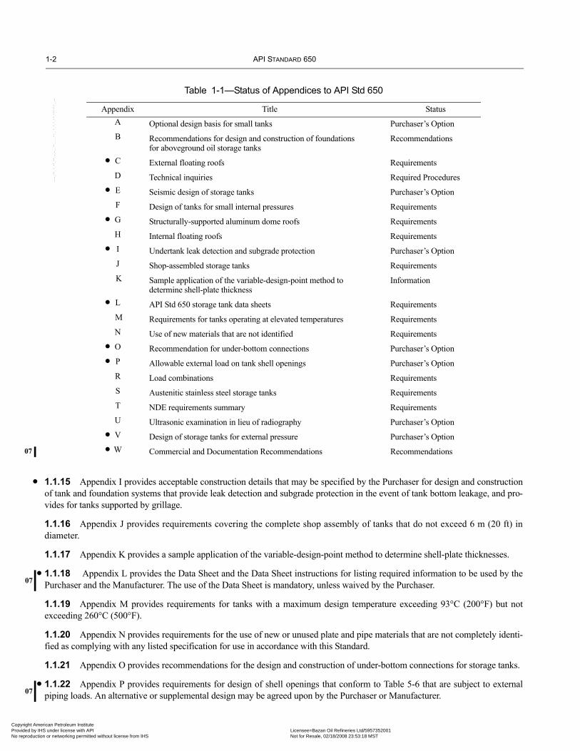
1.1.15 Appendix I provides acceptable construction details that may be specified by the Purchaser for design and constructionof tank and foundation systems that provide leak detection and subgrade protection in the event of tank bottom leakage, and pro-vides for tanks supported by grillage.
1.1.16 Appendix J provides requirements covering the complete shop assembly of tanks that do not exceed 6 m (20 ft) indiameter.
1.1.17 Appendix K provides a sample application of the variable-design-point method to determine shell-plate thicknesses.
1.1.18 Appendix L provides the Data Sheet and the Data Sheet instructions for listing required information to be used by thePurchaser and the Manufacturer. The use of the Data Sheet is mandatory, unless waived by the Purchaser.
1.1.19 Appendix M provides requirements for tanks with a maximum design temperature exceeding 93°C (200°F) but notexceeding 260°C (500°F).
1.1.20 Appendix N provides requirements for the use of new or unused plate and pipe materials that are not completely identi-fied as complying with any listed specification for use in accordance with this Standard.
1.1.21 Appendix O provides recommendations for the design and construction of under-bottom connections for storage tanks.
1.1.22 Appendix P provides requirements for design of shell openings that conform to Table 5-6 that are subject to externalpiping loads. An alternative or supplemental design may be agreed upon by the Purchaser or Manufacturer.
Table 1-1—Status of Appendices to API Std 650
Appendix Title StatusA Optional design basis for small tanks Purchaser’s OptionB Recommendations for design and construction of foundations
for aboveground oil storage tanksRecommendations
C External floating roofs RequirementsD Technical inquiries Required ProceduresE Seismic design of storage tanks Purchaser’s Option F Design of tanks for small internal pressures Requirements G Structurally-supported aluminum dome roofs RequirementsH Internal floating roofs RequirementsI Undertank leak detection and subgrade protection Purchaser’s OptionJ Shop-assembled storage tanks Requirements
K Sample application of the variable-design-point method to determine shell-plate thickness
Information
L API Std 650 storage tank data sheets Requirements M Requirements for tanks operating at elevated temperatures RequirementsN Use of new materials that are not identified RequirementsO Recommendation for under-bottom connections Purchaser’s OptionP Allowable external load on tank shell openings Purchaser’s OptionR Load combinations RequirementsS Austenitic stainless steel storage tanks RequirementsT NDE requirements summary RequirementsU Ultrasonic examination in lieu of radiography Purchaser’s OptionV Design of storage tanks for external pressure Purchaser’s OptionW Commercial and Documentation Recommendations Recommendations
•
•
•
•
•
••
••
•
•
--``,,,,,,`,,`,`,`,``,,````,,``-`-`,,`,,`,`,,`---
merican Petroleum Institute IHS under license with API Licensee=Bazan Oil Refineries Ltd/5957352001
Not for Resale, 02/18/2008 23:53:18 MSTtion or networking permitted without license from IHS

WELDED STEEL TANKS FOR OIL STORAGE 1-3
•07
•
07
•
Copyright AmericaProvided by IHS uNo reproduction o
1.1.23 Appendix R provides a description of the load combinations used for the design equations appearing in this Standard.
1.1.24 Appendix S provides requirements for stainless steel tanks.
1.1.25 Appendix T summarizes the requirements for inspection by method of examination and the reference sections within theStandard. The acceptance standards, inspector qualifications, and procedure requirements are also provided. This appendix is notintended to be used alone to determine the inspection requirements within this Standard. The specific requirements listed withineach applicable section shall be followed in all cases.
1.1.26 Appendix U provides requirements covering the substitution of ultrasonic examination in lieu of radiographic exam-ination.
1.1.27 Appendix V provides additional requirements for tanks that are designed to operate under external pressure (vacuum)conditions.
1.1.28 Appendix W provides recommendations covering commercial and documentation issues. Alternative or supplementalrequirements may be mutually agreed upon by the Manufacturer and the Purchaser.
1.2 LIMITATIONS
The rules of this Standard are not applicable beyond the following limits of piping connected internally or externally to the roof,shell, or bottom of tanks constructed according to this Standard:
a. The face of the first flange in bolted flanged connections, unless covers or blinds are provided as permitted in this Standard.b. The first sealing surface for proprietary connections or fittings.c. The first threaded joint on the pipe in a threaded connection to the tank shell.d. The first circumferential joint in welding-end pipe connections if not welded to a flange.
1.3 RESPONSIBILITIES
1.3.1 The Manufacturer is responsible for complying with all provisions of this Standard. Inspection by the Purchaser’s inspec-tor does not negate the Manufacturer’s obligation to provide quality control and inspection necessary to ensure such compliance.The Manufacturer shall also communicate specified requirements to relevant subcontractors or suppliers working at the request ofthe Manufacturer.
1.3.2 The Purchaser shall specify on the Data Sheet, Line 23, the applicable jurisdictional regulations and owner requirementsthat may affect the design and construction of the tank and those that are intended to limit the evaporation or release of liquid con-tents from the tank. Which regulations/requirements, if any, apply depend on many factors such as the business unit the tank isassigned to, the vapor pressure of the liquids stored in the tank, the components of the liquid stored in the tank, the geographiclocation of the tank, the date of construction of the tank, the capacity of the tank, and other considerations. These rules may affectquestions such as 1) which tanks require floating roofs and the nature of their construction; 2) the types and details of seals used inthe floating roof annular rim space and at openings in the roof, 3) details of tank vents, and 4) requirements regarding release pre-vention barriers.
1.3.3 The Purchaser shall provide any jurisdictional site permits that may be required to erect the tank(s), including permitsfor disposal of the hydro-test water. The Manufacturer shall provide all other permits that may be required to complete or trans-port the tank.
1.3.4 The Purchaser retains the right to provide personnel to observe all shop and job site work within the scope of the con-tracted work (including testing and inspection). Such individuals shall be afforded full and free access for these purposes, subjectto safety and schedule constraints.
1.3.5 In this Standard, language indicating that the Purchaser accepts, agrees, reviews, or approves a Manufacturer’s design,work process, manufacturing action, etc., shall not limit or relieve the Manufacturer’s responsibility to conform to specifieddesign codes, project specifications and drawings, and professional workmanship.
1.3.6 The Manufacturer shall advise the Purchaser of any identified conflicts between this Standard and any Purchaser-refer-enced document and request clarification.
1.3.7 In this Standard, language indicating that any particular issue is subject to agreement between the Purchaser and the Man-ufacturer shall be interpreted to require any such agreement to be documented in writing.
--``,,,,,,`,,`,`,`,``,,````,,``-`-`,,`,,`,`,,`---
n Petroleum Institute nder license with API Licensee=Bazan Oil Refineries Ltd/5957352001
Not for Resale, 02/18/2008 23:53:18 MSTr networking permitted without license from IHS

1-4 API STANDARD 650
07
Copyright AmProvided by No reproduc
--``,,,,,,`,,`,`,`,``,,````,,``-`-`,,`,,`,`,,`---
1.4 DOCUMENTATION REQUIREMENTS
See Appendix W and the Data Sheet for the requirements covering the various documents to be developed for the tank. •
erican Petroleum Institute IHS under license with API Licensee=Bazan Oil Refineries Ltd/5957352001
Not for Resale, 02/18/2008 23:53:18 MSTtion or networking permitted without license from IHS

07
Copyright AmericaProvided by IHS uNo reproduction o
--``,,,,,,`,,`,`,`,``,,````,,``-`-`,,`,,`,`,,`---
SECTION 2—REFERENCES
The following standards, codes, specifications, and publications are cited in this Standard. The most recent edition shall be usedunless otherwise specified.
API Std 620 Design and Construction of Large, Welded, Low-Pressure Storage Tanks
RP 651 Cathodic Protection of Aboveground Petroleum Storage Tanks RP 652 Lining of Aboveground Petroleum Storage Tank Bottoms
Std 2000 Venting Atmospheric and Low-Pressure Storage Tanks: Non-refrigerated and RefrigeratedRP 2003 Protection Against Ignitions Arising Out of Static, Lightning, and Stray Currents Publ 2026 Safe Access/Egress Involving Floating Roofs of Storage Tanks in Petroleum Service
RP 2350 Overfill Protection for Storage Tanks in Petroleum Facilities Spec 5L Specification for Line Pipe Manual of Petroleum Measurements Standards (MPMS)
Chapter 19 “Evaporative Loss Measurement”
AAI1
Aluminum Design Manual Aluminum Standards and Data Specifications for Aluminum Sheet Metal Work in Building Construction
ACI2
318 Building Code Requirements for Reinforced Concrete (ANSI/ACI 318) 350 Environmental Engineering Concrete Structures
AISC3
Manual of Steel Construction, Allowable Stress Design
AISI4
T-192 Steel Plate Engineering Data Series—Useful Information—Design of Plate Structures, Volumes I &II
ASCE5
ASCE Std. 7 Minimum Design Loads for Buildings and Other Structures
ASME6
B1.20.1 Pipe Threads, General Purpose (Inch) (ANSI/ASME B1.20.1) B16.1 Cast Iron Pipe Flanges and Flanged Fittings (ANSI/ASME B16.1) B16.5 Pipe Flanges and Flanged Fittings (ANSI/ASME B16.5) B16.21 Nonmetallic Flat Gaskets for Pipe Flanges B16.47 Large Diameter Steel Flanges: NPS 26 Through NPS 60 (ANSI/ASME B16.47) B96.1 Welded Aluminum-Alloy Storage Tanks (ANSI/ASME B96.1) Boiler and Pressure Vessel Code, Section V, “Nondestructive Examination;” Section VIII, “Pressure Vessels,” Division 1;
and Section IX, “Welding and Brazing Qualifications”
1The Aluminum Association Inc., 1525 Wilson Boulevard, Suite 600, Arlington, Virginia 22209, www.aluminum.org.2American Concrete Institute, P.O. Box 9094, Farmington Hills, Michigan 48333, www.aci-int.org.3American Institute of Steel Construction, One East Wacker Drive, Suite 3100, Chicago, Illinois 60601-2001, www.aisc.org.4American Iron and Steel Institute, 1540 Connecticut Avenue, N.W., Suite 705, Washington, D.C. 20036, www.steel.org.5American Society of Civil Engineers, 1801 Alexander Bell Drive, Reston, Virginia 20191-4400, www.asce.org.6ASME International, 3 Park Avenue, New York, New York 10016-5990, www.asme.org.
2-1
n Petroleum Institute nder license with API Licensee=Bazan Oil Refineries Ltd/5957352001
Not for Resale, 02/18/2008 23:53:18 MSTr networking permitted without license from IHS

2-2 API STANDARD 650
07
Copyright AmProvided by No reproduc
-
ASNT7
CP-189 Standard for Qualification and Certification of Nondestructive Testing PersonnelRP SNT-TC-1A Personnel Qualification and Certification in Nondestructive Testing
ASTM8
A 6M/A 6 General Requirements for Rolled Steel Plates, Shapes, Sheet Piling, and Bars for Structural Use A 20M/A 20 General Requirements for Steel Plates for Pressure Vessels A 27M/A 27 Steel Castings, Carbon, for General Application A 36M/A 36 Structural Steel A 53 Pipe, Steel, Black and Hot-Dipped, Zinc-Coated Welded and Seamless A 105M/A 105 Forgings, Carbon Steel, for Piping Components A 106 Seamless Carbon Steel Pipe for High-Temperature Service A 131M/A 131 Structural Steel for Ships A 181M/A 181 Forgings, Carbon Steel, for General-Purpose Piping A 182M/A 182 Forged or Rolled Alloy-Steel Pipe Flanges, Forged Fittings, and Valves and Parts for High-Temperature
Service A 193M/A 193 Alloy-Steel and Stainless Steel Bolting Materials for High-Temperature Service A 194M/A 194 Carbon and Alloy Steel Nuts for Bolts for High-Pressure and High-Temperature Service A 213M/A 213 Seamless Ferritic and Austenitic Alloy-Steel Boiler, Superheater, and Heat-Exchanger Tubes A 216M/A 216 Standard Specifications for Steel Castings for High-Temperature Service A 234M/A 234 Piping Fittings of Wrought Carbon Steel and Alloy Steel for Moderate and High-Temperature Service A 240M/A 240 Heat-Resisting Chromium and Chromium-Nickel Stainless Steel Plate, Sheet, and Strip for Pressure Vessels A 276 Stainless Steel Bars and Shapes A 283M/A 283 Low and Intermediate Tensile Strength Carbon Steel Plates A 285M/A 285 Pressure Vessel Plates, Carbon Steel, Low- and Intermediate-Tensile Strength A 307 Carbon Steel Bolts and Studs, 60,000 lbf/in.2 Tensile Strength A 312M/A 312 Seamless and Welded Austenitic Stainless Steel Pipes A 320M/A 320 Alloy Steel Bolting Materials for Low-Temperature Service A 333M/A 333 Seamless and Welded Steel Pipe for Low-Temperature Service A 334M/A 334 Seamless and Welded Carbon and Alloy-Steel Tubes for Low-Temperature Service A 350M/A 350 Forgings, Carbon and Low-Alloy Steel, Requiring Notch Toughness Testing for Piping Components A 351M/A 351 Castings, Austenitic, Austenitic-Ferritic (Duplex), for Pressure-Containing Parts A 358M/A 358 Electric-Fusion-Welded Austenitic Chromium-Nickel Alloy Steel Pipe for High-Temperature Service A 370 Test Methods and Definitions for Mechanical Testing of Steel Products A 380 Cleaning, Descaling, and Passivation of Stainless Steel Parts, Equipment, and Systems A 403M/A 403 Wrought Austenitic Stainless Steel Piping Fittings A 420M/A 420 Piping Fittings of Wrought Carbon Steel and Alloy Steel for Low-Temperature Service A 479M/A 479 Stainless Steel Bars and Shapes for Use in Boilers and Other Pressure Vessels A 480M/A 480 Flat-Rolled Stainless and Heat-Resisting Steel Plate, Sheet, and Strip A 516M/A 516 Pressure Vessel Plates, Carbon Steel, for Moderate- and Lower-Temperature Service A 524 Seamless Carbon Steel Pipe for Atmospheric and Lower Temperatures A 537M/A 537 Pressure Vessel Plates, Heat-Treated, Carbon-Manganese-Silicon Steel A 573M/A 573 Structural Carbon Steel Plates of Improved Toughness A 633M/A 633 Normalized High-Strength Low-Alloy Structural Steel A 662M/A 662 Pressure Vessel Plates, Carbon-Manganese, for Moderate and Lower Temperature Service A 671 Electric-Fusion-Welded Steel Pipe for Atmospheric and Lower Temperatures A 678M/A 678 Quenched and Tempered Carbon-Steel and High-Strength Low-Alloy Steel Plates for Structural Applications
7American Society for Nondestructive Testing, 1711 Arlingate Lane, Columbus, Ohio 43228-0518, www.asnt.org.8ASTM, 100 Barr Harbor Drive, West Conshohocken, Pennsylvania 19428-2959, www.astm.org.
-``,,,,,,`,,`,`,`,``,,````,,``-`-`,,`,,`,`,,`---
erican Petroleum Institute IHS under license with API Licensee=Bazan Oil Refineries Ltd/5957352001
Not for Resale, 02/18/2008 23:53:18 MSTtion or networking permitted without license from IHS

WELDED STEEL TANKS FOR OIL STORAGE 2-3
07
07
07
Copyright AmericaProvided by IHS uNo reproduction o
A 737M/A 737 Pressure Vessel Plates, High-Strength, Low-Alloy Steel A 841M/A 841 Standard Specification for Steel Plates for Pressure Vessels, Produced by the Thermo-Mechanical Control
Process (TMCP) A 924M/A 924 General Requirements for Steel Sheet, Metallic-Coated by the Hot-Dip Process A 992M/A 992 Steel for Structural Shapes for Use in Building Framing A 1011M/A 1011Standard Specification for Steel, Sheet and Strip, Hot-Rolled, Carbon, Structural, High-Strength Low-
Alloy and High-Strength Low-Alloy with Improved Formability C 509 Cellular Electrometric Preformed Gasket and Sealing Material D 3453 Flexible Cellular Materials—Urethane for Furniture and Automotive Cushioning, Bedding, and Similar
Applications E 84 Test Method for Surface Burning Characteristics of Building Materials
AWS9
A5.1 Specification for Carbon Steel Covered Arc-Welding Electrodes (ANSI/AWS A5.1) A5.5 Specification for Low-Alloy Steel Covered Arc-Welding Electrodes (ANSI/AWS A5.5) D1.2 Structural Welding Code—Aluminum (ANSI/AWS D1.2)
CSA10
G40.21 Structural Quality Steels, Supplement to National Building Code of Canada
ISO11
630 Structural Steels
NFPA12
NFPA 11 Standard for Low Expansion Foam NFPA 30 Flammable and Combustible Liquids Code NFPA 780 Standard for the Installation of Lightning Protection Systems
Process Industry Practices13
PIP STF05501 Fixed Ladders and Cages Details PIP STF05520 Pipe Railing for Walking and Working Surface Details PIP STF05521 Details for Angle Railings for Walking and Working Surfaces
U.S. EPA14
40 CFR Part 63 National Emission Standards for Hazardous Air Pollutants for Source Categories (HON) Subpart F National Emission Standards for Organic Hazardous Air Pollutants from the Synthetic Organic Chemi-
cal Manufacturing Industry Subpart G National Emission Standards for Organic Hazardous Air Pollutants from the Synthetic Organic Chemi-
cal Manufacturing Industry for Process Vents, Storage Vessels, Transfer Operators, and Waste Water Subpart H National Emission Standards for Organic Hazardous Air Pollutants for Equipment Leaks 40 CFR Part 68 Chemical Accident Prevention Provisions Subpart G Risk Management Plan (RMP) 40 CFR Part 264 Standards for Owners and Operators of Hazardous Waste Treatment, Storage, and Disposal Facilities
(RCRA) Subpart J Tank Systems
9American Welding Society, 550 N.W. LeJeune Road, Miami, Florida 33126, www.aws.org.10Canadian Standards Association, 178 Rexdale Boulevard, Rexdale, Ontario M9W 1R3, www.csa.ca.11International Organization for Standardization. ISO publications can be obtained from the American National Standards Institute (ANSI)and national standards organizations such as the British Standards Institute (BSI), Japanese Industrial Standards (JIS), and Deutsches Institutfuer Normung (German Institute for Standardization [DIN]), www.iso.ch.12National Fire Protection Agency, 1 Batterymarch Park, Quincy, Massachusetts 02169-7474, www.nfpa.org.13Process Industry Practices, 3925 West Braker Lane (R4500), Austin, Texas 78759, www.pip.org.14U.S. Environmental Protection Agency, Ariel Rios Building, 1200 Pennsylvania Avenue, Washington, D.C. 20460, www.epa.gov.
--``,,,,,,`,,`,`,`,``,,````,,``-`-`,,`,,`,`,,`---
n Petroleum Institute nder license with API Licensee=Bazan Oil Refineries Ltd/5957352001
Not for Resale, 02/18/2008 23:53:18 MSTr networking permitted without license from IHS

2-4 API STANDARD 650
07
Copyright AmProvided by No reproduc
U.S. Federal Specifications15
TT-S-00230C Sealing Compound Electrometric Type, Single Component for Caulking, Sealing, and Glazing in Buildingsand Other Structures
ZZ-R-765C Rubber, Silicone (General Specification)
U.S. OSHA16
29 CFR 1910 Subpart D: Walking-Working Surfaces 29 CFR 1910.119 Process Safety Management of Highly Hazardous Chemicals
Other Government Documents Hershfield, D. M. 1961. “Rainfall Frequency Atlas of the United States for Durations from 30 Minutes to 24 Hours and
Return Periods from 1 to 100 Years,” Technical Paper No. 40, Weather Bureau, U.S. Depart-ment of Commerce, Washington, D.C., 115 pp.
WRC17
Bulletin 297 Local Stresses in Cylindrical Shells Due to External Loadings—Supplement to WRC Bulletin No. 107
15Specifications Unit (WFSIS), 7th and D Streets, S.W., Washington, D.C. 20407.16U.S Department of Labor, Occupational Safety and Health Administration, 200 Constitution Avenue, N.W., Washington, D.C. 20210 www.osha.gov.17 The Welding Research Council, 3 Park Avenue, 27th Floor, New York, New York 10016-5902, www.forengineers.org.
--``,,,,,,`,,`,`,`,``,,````,,``-`-`,,`,,`,`,,`---
erican Petroleum Institute IHS under license with API Licensee=Bazan Oil Refineries Ltd/5957352001
Not for Resale, 02/18/2008 23:53:18 MSTtion or networking permitted without license from IHS

07
Copyright AmericaProvided by IHS uNo reproduction o
SECTION 3—DEFINITIONS
3.1 centerline-stacked: The mid-thickness centerlines of plates in all shell courses coincide.
3.2 coating: A protective material applied to external and internal surfaces of a tank, or to inaccessible surfaces (the undersideof the tank bottom) In this Standard, the term includes materials frequently described as painting and lining materials.
3.3 contract: The commercial instrument, including all attachments, used to procure a tank.
3.4 design metal temperature: The lowest temperature considered in the design, which, unless experience or special localconditions justify another assumption, shall be assumed to be 8°C (15°F) above the lowest one-day mean ambient temperature ofthe locality where the tank is to be installed. Isothermal lines of lowest one-day mean temperature are shown in Figure 4-2. Thetemperatures are not related to refrigerated-tank temperatures (see 1.1.1).
3.5 design thickness: The thickness necessary to satisfy tension and compression strength requirements by this Standard or,in the absence of such expressions, by good and acceptable engineering practice for specified design conditions, without regard toconstruction limitations or corrosion allowances.
3.6 double-deck floating roof: The entire roof is constructed of closed-top flotation compartments.
3.7 floating suction line: Internal piping assembly that allows operator to withdraw product from the upper levels of thetank.
3.8 flush-stacked on the inside: The inside surfaces of plates in all shell courses coincide.
3.9 inlet diffusers: Internal fill line piping with impingement plate, baffles, slots, or lateral openings to reduce the velocity ofthe flow entering a tank.
3.10 inspector: The person(s) designated by the Purchaser to perform inspections.
3.11 mandatory: Required sections of the Standard become mandatory if the Standard has been adopted by a Legal Jurisdic-tion or if the Purchaser and the Manufacturer choose to make reference to this Standard on the nameplate or in the Manufacturer’scertification.
3.12 Manufacturer: The party having the primary responsibility to construct the tank (see 1.3 and 10.2).
3.13 maximum design temperature: The highest temperature considered in the design, equal to or greater than the highestexpected operating temperature during the service life of the tank.
3.14 Purchaser: The owner or the owner’s designated agent, such as an engineering contractor.
3.15 Purchaser’s option: A choice to be selected by the Purchaser and indicated on the Data Sheet. When the Purchaserspecifies an option covered by an appendix, the appendix then becomes a requirement.
3.16 recommendation: The criteria provide a good acceptable design and may be used at the option of the Purchaser and theManufacturer.
3.17 requirement: The criteria must be used unless the Purchaser and the Manufacturer agree upon a more stringent alterna-tive design.
3.18 single-deck pontoon floating roof: The outer periphery of the roof consists of closed-top pontoon compartments,with the inner section of the roof constructed of a single deck without flotation means.
3-1
n Petroleum Institute nder license with API Licensee=Bazan Oil Refineries Ltd/5957352001
Not for Resale, 02/18/2008 23:53:18 MSTr networking permitted without license from IHS
--``,,,,,,`,,`,`,`,``,,````,,``-`-`,,`,,`,`,,`---

Copyright AmProvided by No reproduc
--``,,,,,,`,,`,`,`,``,,````,,``-`-`,,`,,`,`,,`---
erican Petroleum Institute IHS under license with API Licensee=Bazan Oil Refineries Ltd/5957352001
Not for Resale, 02/18/2008 23:53:18 MSTtion or networking permitted without license from IHS
•07
•
•
•
Copyright AmericaProvided by IHS uNo reproduction o
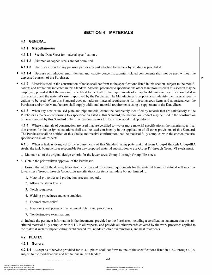
SECTION 4—MATERIALS
4.1 GENERAL
4.1.1 Miscellaneous
4.1.1.1 See the Data Sheet for material specifications.
4.1.1.2 Rimmed or capped steels are not permitted.
4.1.1.3 Use of cast iron for any pressure part or any part attached to the tank by welding is prohibited.
4.1.1.4 Because of hydrogen embrittlement and toxicity concerns, cadmium-plated components shall not be used without theexpressed consent of the Purchaser.
4.1.2 Materials used in the construction of tanks shall conform to the specifications listed in this section, subject to the modifi-cations and limitations indicated in this Standard. Material produced to specifications other than those listed in this section may beemployed, provided that the material is certified to meet all of the requirements of an applicable material specification listed inthis Standard and the material’s use is approved by the Purchaser. The Manufacturer’s proposal shall identify the material specifi-cations to be used. When this Standard does not address material requirements for miscellaneous items and appurtenances, thePurchaser and/or the Manufacturer shall supply additional material requirements using a supplement to the Data Sheet.
4.1.3 When any new or unused plate and pipe material cannot be completely identified by records that are satisfactory to thePurchaser as material conforming to a specification listed in this Standard, the material or product may be used in the constructionof tanks covered by this Standard only if the material passes the tests prescribed in Appendix N.
4.1.4 Where materials of construction are used that are certified to two or more material specifications, the material specifica-tion chosen for the design calculations shall also be used consistently in the application of all other provisions of this Standard.The Purchaser shall be notified of this choice and receive confirmation that the material fully complies with the chosen materialspecification in all respects.
4.1.5 When a tank is designed to the requirements of this Standard using plate material from Group-I through Group-IIIAsteels, the tank Manufacturer responsible for any proposed material substitution to use Group-IV through Group-VI steels must:
a. Maintain all of the original design criteria for the lower stress Group-I through Group IIIA steels.
b. Obtain the prior written approval of the Purchaser.
c. Ensure that all of the design, fabrication, erection and inspection requirements for the material being substituted will meet thelower stress Group-I through Group IIIA specifications for items including but not limited to:
1. Material properties and production process methods.2. Allowable stress levels.
3. Notch toughness.
4. Welding procedures and consumables.
5. Thermal stress relief.
6. Temporary and permanent attachment details and procedures.
7. Nondestructive examinations.
d. Include the pertinent information in the documents provided to the Purchaser, including a certification statement that the sub-stituted material fully complies with 4.1.3 in all respects, and provide all other records covered by the work processes applied tothe material such as impact testing, weld procedures, nondestructive examinations, and heat treatments.
4.2 PLATES
4.2.1 General
4.2.1.1 Except as otherwise provided for in 4.1, plates shall conform to one of the specifications listed in 4.2.2 through 4.2.5,subject to the modifications and limitations in this Standard.
4-1
n Petroleum Institute nder license with API Licensee=Bazan Oil Refineries Ltd/5957352001
Not for Resale, 02/18/2008 23:53:18 MSTr networking permitted without license from IHS
--``,,,,,,`,,`,`,`,``,,````,,``-`-`,,`,,`,`,,`---

4-2 API STANDARD 650
•
Copyright AmProvided by No reproduc
4.2.1.2 Plate for shells, roofs, and bottoms may be ordered on an edge-thickness basis or on a weight (kg/m2 [lb/ft2]) basis, asspecified in 4.2.1.2.1 through 4.2.1.2.3.
4.2.1.2.1 The edge thickness ordered shall not be less than the computed design thickness or the minimum permitted thickness.
4.2.1.2.2 The weight ordered shall be great enough to provide an edge thickness not less than the computed design thickness orthe minimum permitted thickness.
4.2.1.2.3 Whether an edge-thickness or a weight basis is used, an underrun not more than 0.25 mm (0.01 in.) from the com-puted design thickness or the minimum permitted thickness is acceptable.
4.2.1.3 All plates shall be manufactured by the open-hearth, electric-furnace, or basic oxygen process. Steels produced by thethermo-mechanical control process (TMCP) may be used, provided that the combination of chemical composition and inte-grated controls of the steel manufacturing is mutually acceptable to the Purchaser and the Manufacturer, and provided that thespecified mechanical properties in the required plate thicknesses are achieved. Copper-bearing steel shall be used if specified bythe Purchaser.
4.2.1.4 Shell plates are limited to a maximum thickness of 45 mm (1.75 in.) unless a lesser thickness is stated in this Standardor in the plate specification. Plates used as inserts or flanges may be thicker than 45 mm (1.75 in.). Plates thicker than 40 mm(1.5 in.) shall be normalized or quench tempered, killed, made to fine-grain practice, and impact tested.
4.2.2 ASTM Specifications
Plates that conform to the following ASTM specifications are acceptable as long as the plates are within the stated limitations:
a. ASTM A 36M/A 36 for plates to a maximum thickness of 40 mm (1.5 in.). None of the specifications for the appurtenantmaterials listed in Table 1 of ASTM A 36M/A 36 are considered acceptable for tanks constructed under this Standard unless it isexpressly stated in this Standard that the specifications are acceptable.
b. ASTM A 131M/A 131, Grade A, for plates to a maximum thickness of 12.5 mm (0.5 in.); Grade B for plates to a maximumthickness of 25 mm (1 in.); Grade CS for plates to a maximum thickness of 40 mm (1.5 in.) (insert plates and flanges to a maxi-mum thickness of 50 mm [2 in.]); and Grade EH36 for plates to a maximum thickness of 45 mm (1.75 in.) (insert plates andflanges to a maximum thickness of 50 mm [2 in.]).
c. ASTM A 283M/A 283, Grade C, for plates to a maximum thickness of 25 mm (1 in.).
d. ASTM A 285M/A 285, Grade C, for plates to a maximum thickness of 25 mm (1 in.).
e. ASTM A 516M Grades 380, 415, 450, 485/A 516, Grades 55, 60, 65, and 70, for plates to a maximum thickness of 40 mm(1.5 in.) (insert plates and flanges to a maximum thickness of 100 mm [4 in.]).
f. ASTM A 537M/A 537, Class 1 and Class 2, for plates to a maximum thickness of 45 mm (1.75 in.) (insert plates to a maxi-mum thickness of 100 mm [4 in.]).
g. ASTM A 573M Grades 400, 450, 485/A 573, Grades 58, 65, and 70, for plates to a maximum thickness of 40 mm (1.5 in.).
h. ASTM A 633M/A 633, Grades C and D, for plates to a maximum thickness of 45 mm (1.75 in.) (insert plates to a maximumthickness of 100 mm [4.0 in.]).
i. ASTM A 662M/A 662, Grades B and C, for plates to a maximum thickness of 40 mm (1.5 in.).
j. ASTM A 678M/A 678, Grade A, for plates to a maximum thickness of 40 mm (1.5 in.) (insert plates to a maximum thicknessof 65 mm [2.5 in.]) and Grade B for plates to a maximum thickness of 45 mm (1.75 in.) (insert plates to a maximum thickness of65 mm [2.5 in.]). Boron additions are not permitted.
k. ASTM A 737M/A 737, Grade B, for plates to a maximum thickness of 40 mm (1.5 in.).
l. ASTM A 841M/A 841 Grade A, Class 1 and Grade B, Class 2 for plates to a maximum thickness of 40 mm (1.5 in.) (insertplates to a maximum thickness of 65 mm [2.5 in.]).
--``,,,,,,`,,`,`,`,``,,````,,``-`-`,,`,,`,`,,`---
erican Petroleum Institute IHS under license with API Licensee=Bazan Oil Refineries Ltd/5957352001
Not for Resale, 02/18/2008 23:53:18 MSTtion or networking permitted without license from IHS

WELDED STEEL TANKS FOR OIL STORAGE 4-3
•
Copyright AmericaProvided by IHS uNo reproduction o
--``,,,,,,`,,`,`,`,``,,````,,``-`-`,,`,,`,`,,`---
4.2.3 CSA Specifications Plate furnished to CSA G40.21 in Grades 260W/(38W), 300W(44W), and 350W/(50W) is acceptable within the limitationsstated below. (If impact tests are required, Grades 260W/[38W], 300W/[44W], and 350W/[50W] are designated as Grades260WT/[38WT], 300WT/[44WT], and 350WT/[50WT], respectively.) Imperial unit equivalent grades of CSA SpecificationG40.21, shown in parenthesis, are also acceptable.
a. The W grades may be semi-killed or fully killed.
b. Fully killed steel made to fine-grain practice must be specified when required.
c. Elements added for grain refining or strengthening shall be restricted in accordance with Table 4-1.
d. Plates shall have tensile strengths that are not more than 140 MPa (20 ksi) above the minimum specified for the grade.
e. Grades 260W/(38W) and 300W(44W) are acceptable for plate to a maximum thickness of 25 mm (1 in.) if semi-killed and toa maximum thickness of 40 mm (1.5 in.) if fully killed and made to fine-grain practice.
f. Grade 350W(50W) is acceptable for plate to a maximum thickness of 45 mm (1.75 in.) (insert plates to a maximum thicknessof 50 mm [2 in.]) if fully killed and made to fine-grain practice.
4.2.4 ISO SpecificationsPlate furnished to ISO 630 in Grades E 275 and E 355 is acceptable within the following limitations:
a. Grade E 275 in Qualities C and D for plate to a maximum thickness of 40 mm (1.5 in.) and with a maximum manganese con-tent of 1.5% (heat).
b. Grade E 355 in Qualities C and D for plate to a maximum thickness of 45 mm (1.75 in.) (insert plates to a maximum thicknessof 50 mm [2 in.]).
4.2.5 National Standards Plates produced and tested in accordance with the requirements of a recognized national standard and within the mechanicaland chemical limitations of one of the grades listed in Table 4-2 are acceptable when approved by the Purchaser. The require-ments of this group do not apply to the ASTM, CSA, and ISO specifications listed in 4.2.2, 4.2.3, and 4.2.4. For the purposesof this Standard, a national standard is a standard that has been sanctioned by the government of the country from which thestandard originates.
Table 4-1—Maximum Permissible Alloy Content
Alloy Heat Analysis (%) Notes
Columbium 0.05 1, 2, 3
Vanadium 0.10 1, 2, 4
Columbium (≤ 0.05%) plus Vanadium 0.10 1, 2, 3
Nitrogen 0.015 1, 2, 4
Copper 0.35 1, 2
Nickel 0.50 1, 2
Chromium 0.25 1, 2
Molybdenum 0.08 1, 2
1. When the use of these alloys or combinations of them is not included in the material specification, their use shall be at theoption of the plate producer, subject to the approval of the Purchaser. These elements shall be reported when requested bythe Purchaser. When more restrictive limitations are included in the material specification, those shall govern.2. On product analysis, the material shall conform to these requirements, subject to the product analysis tolerances of thespecification.3. When columbium is added either singly or in combination with vanadium, it shall be restricted to plates of 12.5 mm(0.50 in.) maximum thickness unless combined with 0.15% minimum silicon.4. When nitrogen (≤ 0.015%) is added as a supplement to vanadium, it shall be reported, and the minimum ratio of vana-dium to nitrogen shall be 4:1.
•
n Petroleum Institute nder license with API Licensee=Bazan Oil Refineries Ltd/5957352001
Not for Resale, 02/18/2008 23:53:18 MSTr networking permitted without license from IHS

4-4 API STANDARD 650
•
Copyright AmProvided by No reproduc
--``,,,,,,`,,`,`,`,``,,````,,`
4.2.6 General Requirements for Delivery
4.2.6.1 The material furnished shall conform to the applicable requirements of the listed specifications but is not restricted withrespect to the location of the place of manufacture.
4.2.6.2 This material is intended to be suitable for fusion welding. Welding technique is of fundamental importance, and weld-ing procedures must provide welds whose strength and toughness are consistent with the plate material being joined. All weldingperformed to repair surface defects shall be done with low-hydrogen welding electrodes compatible in chemistry, strength, andquality with the plate material.
4.2.6.3 When specified by the plate purchaser, the steel shall be fully killed. When specified by the plate purchaser, fully killedsteel shall be made to fine-grain practice.
4.2.6.4 For plate that is to be made to specifications that limit the maximum manganese content to less than 1.60%, the limit ofthe manganese content may be increased to 1.60% (heat) at the option of the plate producer to maintain the required strengthlevel, provided that the maximum carbon content is reduced to 0.20% (heat) and the weldability of the plate is given consider-ation. The material shall be marked “Mod” following the specification listing. The material shall conform to the product analysistolerances of Table B in ASTM A 6M/A 6.
4.2.6.5 The use or presence of columbium, vanadium, nitrogen, copper, nickel, chromium, or molybdenum shall not exceed thelimitations of Table 4-1 for all Group VI materials (see Table 4-3) and ISO 630, Grade E 355.
4.2.7 Heat Treatment of Plates
4.2.7.1 When specified by the plate purchaser, fully killed plates shall be heat treated to produce grain refinement by either nor-malizing or heating uniformly for hot forming. If the required treatment is to be obtained in conjunction with hot forming, thetemperature to which the plates are heated for hot forming shall be equivalent to and shall not significantly exceed the normaliz-ing temperature. If the treatment of the plates is not specified to be done at the plate producer’s plant, testing shall be carried out inaccordance with 4.2.7.2.
4.2.7.2 When a plate purchaser elects to perform the required normalizing or fabricates by hot forming (see 4.2.7.1), the platesshall be accepted on the basis of mill tests made on full-thickness specimens heat treated in accordance with the plate purchaser’sorder. If the heat-treatment temperatures are not indicated on the contract, the specimens shall be heat treated under conditionsconsidered appropriate for grain refinement and for meeting the test requirements. The plate producer shall inform the plate pur-chaser of the procedure followed in treating the specimens at the steel mill.
4.2.7.3 On the purchase order, the plate purchaser shall indicate to the plate producer whether the producer shall perform theheat treatment of the plates.
Table 4-2—Acceptable Grades of Plate Material Produced to National Standards (See 4.2.5)
Mechanical Properties Chemical Composition
Tensile Strengtha Minimum Yield
StrengthcMaximum Thickness
MaximumPercentCarbon
Maximum Percent
Phosphorus and SulfurMinimumc Maximum
Gradeb MPa ksi MPa ksi MPa ksi mm in. Heat Product Heat Product235d 360 52 510 74 235 34 20 0.75 0.20 0.24 0.04 0.05250 400 58 530 77 250 36 40 1.5 0.23 0.27 0.04 0.05275 430 62 560 81 275 40 40 1.5 0.25 0.29 0.04 0.05
aThe location and number of test specimens, elongation and bend tests, and acceptance criteria are to be in accordance with the appropriatenational standard, ISO standard, or ASTM specification.bSemi-killed or fully killed quality; as rolled, controlled-rolled or TMCP (20 mm [0.75 in.] maximum when controlled-rolled steel or TMCP isused in place of normalized steel), or normalized. cYield strength ÷ tensile strength ≤ 0.75, based on the minimum specified yield and tensile strength unless actual test values are required by thePurchaser. dNonrimming only.
`-`-`,,`,,`,`,,`---
erican Petroleum Institute IHS under license with API Licensee=Bazan Oil Refineries Ltd/5957352001
Not for Resale, 02/18/2008 23:53:18 MSTtion or networking permitted without license from IHS

WELDED STEEL TANKS FOR OIL STORAGE 4-5
•
•
•
07
Copyright AmericaProvided by IHS uNo reproduction o
4.2.7.4 Subject to the Purchaser’s approval, controlled-rolled or thermo-mechanical-control-process (TMCP) plates (platesproduced by a mechanical-thermal rolling process designed to enhance notch toughness) may be used where normalized platesare required. Each plate-as-rolled shall receive Charpy V-notch impact energy testing in accordance with 4.2.8, 4.2.9, and 4.2.10.When controlled-rolled or TMCP steels are used, consideration should be given to the service conditions outlined in 5.3.3.
4.2.7.5 The tensile tests shall be performed on each plate as heat treated.
4.2.8 Impact Testing of Plates
4.2.8.1 When required by the Purchaser or by 4.2.7.4 and 4.2.9, a set of Charpy V-notch impact specimens shall be taken fromplates after heat treatment (if the plates have been heat treated), and the specimens shall fulfill the stated energy requirements. Testcoupons shall be obtained adjacent to a tension-test coupon. Each full-size impact specimen shall have its central axis as close tothe plane of one-quarter plate thickness as the plate thickness will permit.
4.2.8.2 When it is necessary to prepare test specimens from separate coupons or when plates are furnished by the plate pro-ducer in a hot-rolled condition with subsequent heat treatment by the fabricator, the procedure shall conform to ASTM A 20.
4.2.8.3 An impact test shall be performed on three specimens taken from a single test coupon or test location. The averagevalue of the specimens (with no more than one specimen value being less than the specified minimum value) shall comply withthe specified minimum value. If more than one value is less than the specified minimum value, or if one value is less than two-thirds the specified minimum value, three additional specimens shall be tested, and each of these must have a value greater than orequal to the specified minimum value.
4.2.8.4 The test specimens shall be Charpy V-notch Type A specimens (see ASTM A 370), with the notch perpendicular to thesurface of the plate being tested.
4.2.8.5 For a plate whose thickness is insufficient to permit preparation of full-size specimens (10 mm × 10 mm), tests shall bemade on the largest subsize specimens that can be prepared from the plate. Subsize specimens shall have a width along the notchof at least 80% of the material thickness.
4.2.8.6 The impact energy values obtained from subsize specimens shall not be less than values that are proportional to theenergy values required for full-size specimens of the same material.
4.2.8.7 The testing apparatus, including the calibration of impact machines and the permissible variations in the temperature ofspecimens, shall conform to ASTM A 370 or an equivalent testing apparatus conforming to national standards or ISO standards.
4.2.9 Toughness Requirements
4.2.9.1 The thickness and design metal temperature of all shell plates, shell reinforcing plates, shell insert plates, bottom plateswelded to the shell, plates used for manhole and nozzle necks, plate-ring shell-nozzle flanges, blind flanges, and manhole coverplates shall be in accordance with Figure 4-1. Notch toughness evaluation of plate-ring flanges, blind flanges, and manhole coverplates shall be based on “governing thickness” as defined in 4.5.5.3. In addition, plates more than 40 mm (1.5 in.) thick shall be ofkilled steel made to fine-grain practice and heat treated by normalizing, normalizing and tempering, or quenching and tempering,and each plate as heat treated shall be impact tested according to 4.2.10.2. Each TMCP A 841 plate-as-rolled shall be impacttested. Impact test temperature and required energy shall be in accordance with 4.2.10.2 in lieu of the default temperature andenergy given in A 841.
4.2.9.2 Plates less than or equal to 40 mm (1.5 in.) thick, except controlled-rolled plates (see 4.2.7.4), may be used at or abovethe design metal temperatures indicated in Figure 4-1 without being impact tested. To be used at design metal temperatures lowerthan the temperatures indicated in Figure 4-1, plates shall demonstrate adequate notch toughness in accordance with 4.2.10.3unless 4.2.10.2 or 4.2.10.4 has been specified by the Purchaser. For heat-treated material, notch toughness shall be demonstratedon each plate as heat treated when 4.2.10.2 requirements are specified. Isothermal lines of lowest one-day mean temperature areshown in Figure 4-2.
4.2.9.3 Plate used to reinforce shell openings and insert plates shall be of the same material as the shell plate to which they areattached or shall be of any appropriate material listed in Table 4-3 and Figure 4-1. Except for nozzle and manway necks, the mate-rial shall be of equal or greater yield and tensile strength and shall be compatible with the adjacent shell material (see 4.2.9.1 and5.7.2.3, Item d).
n Petroleum Institute nder license with API Licensee=Bazan Oil Refineries Ltd/5957352001
Not for Resale, 02/18/2008 23:53:18 MSTr networking permitted without license from IHS
--``,,,,,,`,,`,`,`,``,,````,,``-`-`,,`,,`,`,,`---

4-6 API STANDARD 650
Copyright AmProvided by No reproduc
4.2.9.4 The requirements in 4.2.9.3 apply only to shell nozzles and manholes. Materials for roof nozzles and manholes do notrequire special toughness.
4.2.10 Toughness Procedure
4.2.10.1 When a material’s toughness must be determined, it shall be done by one of the procedures described in 4.2.10.2through 4.2.10.4, as specified in 4.2.9.
4.2.10.2 Each plate as rolled or heat treated shall be impact tested in accordance with 4.2.8 at or below the design metal tem-perature to show Charpy V-notch longitudinal (or transverse) values that fulfill the minimum requirements of Table 4-4 (see4.2.8 for the minimum values for one specimen and for subsize specimens). As used here, the term plate as rolled refers to theunit plate rolled from a slab or directly from an ingot in its relation to the location and number of specimens, not to the condi-tion of the plate.
Figure 4-1—Minimum Permissible Design Metal Temperature for Materials Used in Tank Shells without Impact Testing
–60
–50
–40
–30
–20
–10
0
10
20
30
40
50
60
°F
–51
–46
–40
–34
–29
–23
–18
–12
–7
–1
4
10
16
°C
–51
–46
–40
–34
–29
–23
–18
–12
–7
–1
4
10
16
°C
–60
–50
–40
–30
–20
–10
0
10
20
30
40
50
60
°F
Des
ign
met
al te
mpe
ratu
re
Group VI and Group VIA
Group V
See Note 2
Group I
Group II
Group III
Group IV
Group IIIA
See Note 1
Group IVA
Group IIA
Thickness, including corrosion allowance
6mm 12.5 19 25 32 380.25in. 0.50 0.75 1.00 1.25 1.50
Notes:1. The Group II and Group V lines coincide at thicknesses less than 12.5 mm (1/2 in.).2. The Group III and Group IIIA lines coincide at thicknesses less than 12.5 mm (1/2 in.).3. The materials in each group are listed in Table 4-3.4. This figure is not applicable to controlled-rolled plates (see 4.2.7.4).5. Use the Group IIA and Group VIA curves for pipe and flanges (see 4.5.5.2 and 4.5.5.3).
erican Petroleum Institute IHS under license with API Licensee=Bazan Oil Refineries Ltd/5957352001
Not for Resale, 02/18/2008 23:53:18 MSTtion or networking permitted without license from IHS
--``,,,,,,`,,`,`,`,``,,````,,``-`-`,,`,,`,`,,`---
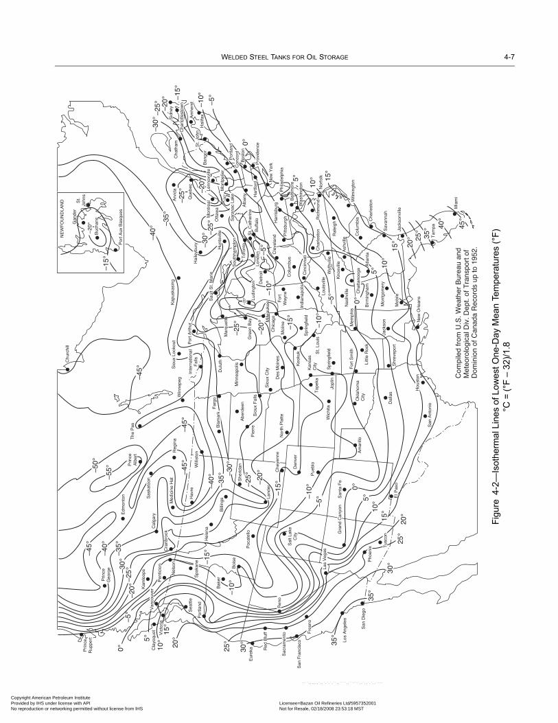
WELDED STEEL TANKS FOR OIL STORAGE 4-7
Copyright AmericaProvided by IHS uNo reproduction o
El P
aso
San
ta F
e
Am
arill
o
San
Ant
onio
Hou
ston
Dal
las
Okl
ahom
aC
ityLi
ttle
Roc
k
For
t Sm
ith
Shr
evep
ort
Jack
son New
Orle
ans
Mon
tgom
ery
Birm
ingh
am
Mob
ile
Mem
phis
Nas
hvill
e
Kno
xvill
e
Cha
ttano
oga
Spr
ingf
ield
Jopl
inW
ichi
ta
Top
eka
Keo
kuk
Kan
sas
City
St.
Loui
s
Spr
ingf
ield
For
tW
ayne
Col
umbu
s
Loui
svill
e
Cle
vela
ndD
es M
oine
sN
orth
Pla
tte
Min
neap
olis
Sio
ux F
alls
Sio
ux C
ity
Abe
rdee
n
Pie
rre
Mol
ine
Chu
rchi
ll
The
Pas
Win
nepe
g
Kap
uska
sing
Inte
rnat
iona
lF
alls
Por
t Aux
Bas
ques
St.
John
s
NE
WF
OU
ND
LAN
D
Buc
hans
Far
goD
ulut
h
Edm
onto
n
Med
icin
e H
at
Hav
re
Bill
ings
She
ridanP
rince
Alb
ert
Sas
kato
on
Reg
ina
Will
isto
n
Hel
ena
Cla
yoqu
ot
Kam
loop
s
Sea
ttle
Boi
se
Spo
kane
Bak
er
Por
tland
Pen
ticio
n
Nel
son
Cra
nbro
okV
icto
ria
Van
couv
er
Cha
tham
Ban
gor
Hal
ifax
St.
John
Hun
tsvi
lleO
ttaw
a
Pitt
sbur
gh
Buf
falo
Alb
any
Ral
eigh
Nor
folk
Col
umbi
a Cha
rlest
on
Sav
anna
h
Jack
sonv
ille
Tam
pa
Mia
mi
Pue
blo
Den
ver
Poc
atel
lo
San
Die
go
Los
Ang
eles
San
Fra
ncis
co
Eur
eka
Com
pile
d fr
om U
.S. W
eath
er B
urea
u an
dM
eteo
rolo
gica
l Div
. Dep
t. of
Tra
nspo
rt o
fD
omin
ion
of C
anad
a R
ecor
ds u
p to
195
2.
Chi
cago
Det
roit
Arv
ida
35°
35°
30°
25°
20°
25°
20°
15°
10°5°
0°
10°
15°
10°
45°
40°
35°
25°
20°
5°
0°–5°
–10°
–15°
–20°
–25°
–10°
–5°
–40°
–35°
–30°
Hai
leyb
ury
–20°
–30°
–30°
–25° –2
0° –15°
–10°
–5°
0°
5° 15°
–20°
–15°
Cal
gary
30°
15°10
°5°
0°
–5°–1
0°
–15°–2
5°–30°
–20°
–35°
–40°
–45°
–5°
–20°
–25°–3
0°–3
5°
–40°
–45°
–55°–5
0°
–45°
–20°
Ric
hmon
dC
harle
ston
Cin
cinn
ati
Was
hing
ton
Bal
timor
eNew
Yor
k
Phi
lade
lphi
a
Har
tford
Bos
ton
Con
cord
Cha
rlotte
stow
n
Sid
ney
Que
bec
Sar
anac
Lak
e
Mon
tpel
ier
Lenn
oxvi
lleS
ault
St.
Mar
ie
Sou
thha
mpt
on
Tor
onto
Lond
onLu
ding
ton
Gre
en B
ay
Mar
quet
te
Por
t Art
hur
Sio
ux L
ooko
ut
Milw
auke
e
Che
yenn
e
Land
erR
ed B
luff
Sac
ram
ento F
resn
o
Ren
o
Prin
ceG
eorg
e
Sal
t Lak
eC
ity
Tus
con
Pho
enix
Har
risbu
rg
St.
Cat
herin
e
Por
tland
Gan
der
Wilm
ingt
on
Ash
ville
Atla
nta
Indi
anap
olis
Wyt
hvill
e
Prin
ceR
uppe
rt
Mon
trea
l
Am
hers
t
Pro
vide
nce
–15°
–10°
Las
Veg
as
Bis
mar
k
–45°
–25°
–25°
Gra
nd C
anyo
n
Figu
re4-
2—Is
othe
rmal
Lin
es o
f Low
est O
ne-D
ay M
ean
Tem
pera
ture
s (°
F)
°C =
(°F
– 32
)/1.8
n Petroleum Institute nder license with API Licensee=Bazan Oil Refineries Ltd/5957352001
Not for Resale, 02/18/2008 23:53:18 MSTr networking permitted without license from IHS
--``,,,,,,`,,`,`,`,``,,````,,``-`-`,,`,,`,`,,`---

4-8 API STANDARD 650
Copyright AmProvided by No reproduc
Table 4-3a—Material Groups, SI Units (See Figure 4-1 and Note 1 Below)
Group IAs Rolled,Semi-killed
Group IIAs Rolled,
Killed or Semi-killed
Group IIIAs Rolled, Killed
Fine-Grain Practice
Group IIIANormalized, KilledFine-Grain Practice
Material Notes Material Notes Material Notes Material Notes
A 283M C 2 A 131M B 7 A 573M-400 A 131M CS
A 285M C 2 A 36M 2, 6 A 516M-380 A 573M-400 10
A 131M A 2 G40.21-260W A 516M-415 A 516M-380 10
A 36M 2, 3 Grade 250 5, 8 G40.21-260W 9 A 516M-415 10
Grade 235 3, 5 Grade 250 5, 9 G40.21-260W 9, 10
Grade 250 6 Grade 250 5, 9, 10
Group IVAs Rolled, Killed
Fine-Grain Practice
Group IVAAs Rolled, Killed
Fine-Grain Practice
Group VNormalized, KilledFine-Grain Practice
Group VINormalized or
Quenched and Tempered, Killed Fine-Grain Practice
Reduced Carbon
Material Notes Material Notes Material Notes Material Notes
A 573M-450 A 662M C A 573M-485 10 A 131M EH 36A 573M-485 A 573M-485 11 A 516M-450 10 A 633M CA 516M-450 G40.21-300W 9, 11 A 516M-485 10 A 633M DA 516M-485 G40.21-350W 9, 11 G40.21-300W 9, 10 A 537M Class 1A 662M B G40.21-350W 9, 10 A 537M Class 2 13G40.21-300W 9 A 678M AG40.21-350W 9 A 678M B 13E 275 4, 9 A 737M BE 355 9 A 841, Grade A, Class 1
A 841, Grade B, Class 212, 13, 1412, 13, 14
Grade 275 5, 9
Notes:1. Most of the listed material specification numbers see ASTM specifications (including Grade or Class); there are, however, some exceptions:
G40.21 (including Grade) is a CSA specification; Grades E 275 and E 355 (including Quality) are contained in ISO 630; and Grade 235, Grade250, and Grade 275 are related to national standards (see 4.2.5).
2. Must be semi-killed or killed.3. Thickness ≤ 20 mm.4. Maximum manganese content of 1.5%.5. Thickness 20 mm maximum when controlled-rolled steel is used in place of normalized steel.6. Manganese content shall be 0.80% – 1.2% by heat analysis for thicknesses greater than 20 mm, except that for each reduction of 0.01% below
the specified carbon maximum, an increase of 0.06% manganese above the specified maximum will be permitted up to the maximum of 1.35%.Thicknesses ≤ 20 mm shall have a manganese content of 0.80% – 1.2% by heat analysis.
7. Thickness ≤ 25 mm.8. Must be killed.9. Must be killed and made to fine-grain practice.10.Must be normalized.11. Must have chemistry (heat) modified to a maximum carbon content of 0.20% and a maximum manganese content of 1.60% (see 4.2.6.4).12.Produced by the thermo-mechanical control process (TMCP).13.See 5.7.4.6 for tests on simulated test coupons for material used in stress-relieved assemblies.14.See 4.2.9 for impact test requirements (each plate-as-rolled tested).
--``,,,,,,`,,`,`,`,``,,````,,``-`-`,,`,,`,`,,`---
erican Petroleum Institute IHS under license with API Licensee=Bazan Oil Refineries Ltd/5957352001
Not for Resale, 02/18/2008 23:53:18 MSTtion or networking permitted without license from IHS

WELDED STEEL TANKS FOR OIL STORAGE 4-9
Copyright AmericaProvided by IHS uNo reproduction o
Table 4-3b—Material Groups, US Customary Units (See Figure 4-1 and Note 1 Below)
Group IAs Rolled,Semi-killed
Group IIAs Rolled,
Killed or Semi-killed
Group IIIAs Rolled, Killed
Fine-Grain Practice
Group IIIANormalized, KilledFine-Grain Practice
Material Notes Material Notes Material Notes Material Notes
A 283 C 2 A 131 B 7 A 573-58 A 131 CS
A 285 C 2 A 36 2, 6 A 516-55 A 573-58 10
A 131 A 2 G40.21-38W A 516-60 A 516-55 10
A 36 2, 3 Grade 250 5, 8 G40.21-38W 9 A 516-60 10
Grade 235 3, 5 Grade 250 5, 9 G40.21-38W 9, 10
Grade 250 6 Grade 250 5, 9, 10
Group IVAs Rolled, Killed
Fine-Grain Practice
Group IVAAs Rolled, Killed
Fine-Grain Practice
Group VNormalized, KilledFine-Grain Practice
Group VINormalized or
Quenched and Tempered, Killed Fine-Grain Practice
Reduced Carbon
Material Notes Material Notes Material Notes Material Notes
A 573-65 A 662 C A 573-70 10 A 131 EH 36A 573-70 A 573-70 11 A 516-65 10 A 633 CA 516-65 G40.21-44W 9, 11 A 516-70 10 A 633 DA 516-70 G40.21-50W 9, 11 G40.21-44W 9, 10 A 537 Class 1A 662 B G40.21-50W 9, 10 A 537 Class 2 13G40.21-44W 9 A 678 AG40.21-50W 9 A 678 B 13E 275 4, 9 A 737 BE 355 9 A 841, Grade A, Class 1
A 841, Grade B, Class 212, 13, 1412, 13, 14
Grade 275 5, 9
Notes:1. Most of the listed material specification numbers see ASTM specifications (including Grade or Class); there are, however, some exceptions:
G40.21 (including Grade) is a CSA specification; Grades E 275 and E 355 (including Quality) are contained in ISO 630; and Grade 235, Grade250, and Grade 275 are related to national standards (see 4.2.5).
2. Must be semi-killed or killed.3. Thickness ≤ 0.75 in.4. Maximum manganese content of 1.5%.5. Thickness 0.75 in. maximum when controlled-rolled steel is used in place of normalized steel.6. Manganese content shall be 0.80% – 1.2% by heat analysis for thicknesses greater than 0.75 in., except that for each reduction of 0.01% below
the specified carbon maximum, an increase of 0.06% manganese above the specified maximum will be permitted up to the maximum of 1.35%.Thicknesses ≤ 0.75 in. shall have a manganese content of 0.80% – 1.2% by heat analysis.
7. Thickness ≤ 1 in.8. Must be killed.9. Must be killed and made to fine-grain practice.10.Must be normalized.11. Must have chemistry (heat) modified to a maximum carbon content of 0.20% and a maximum manganese content of 1.60% (see 4.2.6.4).12.Produced by the thermo-mechanical control process (TMCP).13.See 5.7.4.6 for tests on simulated test coupons for material used in stress-relieved assemblies.14.See 4.2.9 for impact test requirements (each plate-as-rolled tested).
--``,,,,,,`,,`,`,`,``,,````,,``-`-`,,`,,`,`,,`---
n Petroleum Institute nder license with API Licensee=Bazan Oil Refineries Ltd/5957352001
Not for Resale, 02/18/2008 23:53:18 MSTr networking permitted without license from IHS

4-10 API STANDARD 650
•
•
•
Copyright AmProvided by No reproduc
4.2.10.3 The thickest plate from each heat shall be impact tested in accordance with 4.2.8 and shall fulfill the impact require-ments of 4.2.10.2 at the design metal temperature.
4.2.10.4 The Manufacturer shall submit to the Purchaser test data for plates of the material demonstrating that based on pastproduction from the same mill, the material has provided the required toughness at the design metal temperature.
4.3 SHEETSSheets for fixed and floating roofs shall conform to ASTM A 1011M, Grade 33. They shall be made by the open-hearth or basicoxygen process. Copper-bearing steel shall be used if specified on the purchase order. Sheets may be ordered on either a weight ora thickness basis, at the option of the tank Manufacturer.
4.4 STRUCTURAL SHAPES
4.4.1 Structural steel shall conform to one of the following:
a. ASTM A 36M/A 36.
b. ASTM A 131M/A 131.
c. ASTM A 992M/ A 992.
d. Structural Steels listed in AISC Specification for Structural Steel Buildings, Allowable Stress Design.
e. CSA G40.21, Grades 260W(38W), 300W(44W), 350W(50W), 260WT(38WT), 300WT(44WT), and 350WT(50WT). Impe-rial unit equivalent grades of CSA Specification G40.21, shown in parenthesis, are also acceptable.
f. ISO 630, Grade E 275, Qualities B, C, and D.
g. Recognized national standards. Structural steel that is produced in accordance with a recognized national standard and thatmeets the requirements of Table 4-2 is acceptable when approved by the Purchaser.
4.4.2 All steel for structural shapes shall be made by the open-hearth, electric-furnace, or basic oxygen process. Copper-bearingsteel is acceptable when approved by the Purchaser.
4.4.3 Not all of the structural steel shapes listed in AISC (4.4.1 [d]) and other national standards (4.4.1[g]) are well suited forwelding. Material selection for structural shapes requiring welded connections shall include confirmation of the material’s weld-ability from the structural shape manufacturer, other reputable sources, or by weld testing. Structural steel shapes having poorweldability shall only be used for bolted connection designs
Table 4-4—Minimum Impact Test Requirements for Plates (See Note)
Plate Materiala and Thickness (t) in mm (in.)
Average Impact Value of Three Specimensb
Thickness Longitudinal Transverse
mm in. J ft-lbf J ft-lbf
Groups I, II, III, and IIIAt ≤ maximum thicknesses in 4.2.2 through 4.2.5
20 15 18 13
Groups IV, IVA, V, and VI (except quenched and tempered and TMCP)
t ≤ 4040 < t ≤ 4545 < t ≤ 5050 < t ≤ 100
t ≤ 1.51.5 < t ≤ 1.751.75 < t ≤ 22 < t ≤ 4
41485468
30354050
27344154
20253040
Group VI (quenched and tempered and TMCP) t ≤ 4040 < t ≤ 4545 < t ≤ 5050 < t ≤ 100
t ≤ 1.51.5 < t ≤ 1.751.75 < t ≤ 22 < t ≤ 4
48546168
35404550
34414854
25303540
aSee Table 4-3.bInterpolation is permitted to the nearest joule (ft-lbf).Note: For plate ring flanges, the minimum impact test requirements for all thicknesses shall be those for t ≤ 40 mm (1.5 in.).
erican Petroleum Institute IHS under license with API Licensee=Bazan Oil Refineries Ltd/5957352001
Not for Resale, 02/18/2008 23:53:18 MSTtion or networking permitted without license from IHS
--``,,,,,,`,,`,`,`,``,,````,,``-`-`,,`,,`,`,,`---

WELDED STEEL TANKS FOR OIL STORAGE 4-11
07
Copyright AmericaProvided by IHS uNo reproduction o
--``,,,,,,`,,`,`,`,``,,````,,``-`-`,,`,,`,`,,`---
4.5 PIPING AND FORGINGS
4.5.1 Unless otherwise specified in this Standard, pipe and pipe couplings and forgings shall conform to the specificationslisted in 4.5.1.1 and 4.5.1.2 or to national standards equivalent to the specifications listed.
4.5.1.1 The following specifications are acceptable for pipe and pipe couplings:
a. API Spec 5L, Grades A, B, and X42.
b. ASTM A 53, Grades A and B.
c. ASTM A 106, Grades A and B.
d. ASTM A 234M/A 234, Grade WPB.
e. ASTM A 333M/A 333, Grades 1 and 6.
f. ASTM A 334M/A 334, Grades 1 and 6.
g. ASTM A 420M/A 420, Grade WPL6.
h. ASTM A 524, Grades I and II.
i. ASTM A 671 (see 4.5.3).
4.5.1.2 The following specifications are acceptable for forgings:
a. ASTM A 105M/A 105.
b. ASTM A 181M/A 181.
c. ASTM A 350M/A 350, Grades LF1 and LF2.
4.5.2 Unless ASTM A 671 pipe is used (electric-fusion-welded pipe) (see 4.5.3), material for shell nozzles and shell manholenecks shall be seamless pipe, seamless forging, or plate material as specified in 4.2.9.1. When shell materials are Group IV, IVA,V, or VI, seamless pipe shall comply with ASTM A 106, Grade B; ASTM A 524; ASTM A 333M/ A 333, Grade 6; or ASTM A334M/A 334, Grade 6.
4.5.3 When ASTM A 671 pipe is used for shell nozzles and shell manhole necks, it shall comply with the following:
a. Material selection shall be limited to Grades CA 55, CC 60, CC 65, CC 70, CD 70, CD 80, CE 55, and CE 60.
b. The pipe shall be pressure tested in accordance with 8.3 of ASTM A 671.
c. The plate specification for the pipe shall satisfy the requirements of 4.2.7, 4.2.8, and 4.2.9 that are applicable to that platespecification.
d. Impact tests for qualifying the welding procedure for the pipe longitudinal welds shall be performed in accordance with 9.2.2.
4.5.4 Weldable-quality pipe that conforms to the physical properties specified in any of the standards listed in 4.5.1 may beused for structural purposes with the allowable stresses stated in 5.10.3.
4.5.5 Except as covered in 4.5.3, the toughness requirements of pipe and forgings to be used for shell nozzles and manholesshall be established as described in 4.5.5.1 through 4.5.5.4.
4.5.5.1 Piping materials made according to ASTM A 333M/A 333, A 334M/A 334, A 350M/A 350, and A 420, Grade WPL6may be used at a design metal temperature no lower than the impact test temperature required by the ASTM specification for theapplicable material grade without additional impact tests (see 4.5.5.4).
4.5.5.2 Other pipe and forging materials shall be classified under the material groups shown in Figure 4-1 as follows:
a. Group IIA—API Spec 5L, Grades A, B, and X42; ASTM A 106, Grades A and B; ASTM A 53, Grades A and B; ASTM A181M/A 181; ASTM A 105M/A 105; and A 234M/A234, Grade WPB.
b. Group VIA—ASTM A 524, Grades I and II.
n Petroleum Institute nder license with API Licensee=Bazan Oil Refineries Ltd/5957352001
Not for Resale, 02/18/2008 23:53:18 MSTr networking permitted without license from IHS

4-12 API STANDARD 650
07
07
•
•
07
Copyright AmProvided by No reproduc
4.5.5.3 The materials in the groups listed in 4.5.5.2 may be used at nominal thicknesses, including corrosion allowance, at adesign metal temperature no lower than those shown in Figure 4-1 without impact testing (see 4.5.5.4 and Figure 4-3). The gov-erning thicknesses to be used in Figure 4-1 shall be as follows:
a. For butt-welded joints, the nominal thickness of the thickest welded joint.
b. For corner or lap welds, the thinner of the two parts joined.
c. For nonwelded parts such as bolted blind flanges and manhole covers, 1/4 of their nominal thickness.
4.5.5.4 When impact tests are required by 4.5.5.1 or 4.5.5.3, they shall be performed in accordance with the requirements,including the minimum energy requirements, of ASTM A 333M/A 333, Grade 6, for pipe or ASTM A 350M/A 350, Grade LF1,for forgings at a test temperature no higher than the design metal temperature. Except for the plate specified in 4.2.9.2, the materi-als specified in 4.5.1 and 4.5.2 for shell nozzles, shell manhole necks, and all forgings used on shell openings shall have a mini-mum Charpy V-notch impact strength of 18 J (13 ft-lbf) (full-size specimen) at a temperature no higher than the design metaltemperature.
4.6 FLANGES
4.6.1 Hub, slip-on, welding, and welding-neck flanges shall conform to the material requirements of ASME B16.5 for forgedcarbon steel flanges. Plate material used for nozzle flanges shall have physical properties better than or equal to those required byASME B16.5. Shell-nozzle flange material shall conform to 4.2.9.1.
4.6.2 For nominal pipe sizes greater than NPS 24, flanges that conform to ASME B16.47, Series B, may be used, subject to thePurchaser’s approval. Particular attention should be given to ensuring that mating flanges of appurtenances are compatible.
4.7 BOLTING
a. Unless otherwise specified on the Data Sheet, Table 2, flange bolting shall conform to ASTM A 193 B7 and the dimensionsspecified in ASME B18.2.1. Nuts shall conform to ASTM A 194 Grade 2H and the dimensions specified in ASME B18.2.2. Bothshall be heavy hex pattern. All bolts and nuts shall be threaded in accordance with ASME B1.13M (SI), or with ASME B1.1(US)as follows:
1. Bolts up to and including 1 in. diameter: UNC Class 2A fit2. Nuts for bolts up to and including 1 in. diameter: UNC Class 2B fit
3. Bolts 1.125 in. diameter and larger: 8N Class 2A fit
4. Nuts for bolts 1.125 in. diameter and larger: 8N Class 2B fit
b. Unless otherwise specified on the Data Sheet, Table 2, all anchors shall be threaded, galvanized ASTM A 36 round bar withgalvanized heavy hex nuts.
c. All other bolting shall conform to ASTM A 307 or A 193M/A 193. A 325M/A 325 may be used for structural purposes only.The Purchaser should specify on the order what shape of bolt heads and nuts is desired and whether regular or heavy dimensionsare desired.
4.8 WELDING ELECTRODES
4.8.1 For the welding of materials with a minimum tensile strength less than 550 MPa (80 ksi), the manual arc-welding elec-trodes shall conform to the E60 and E70 classification series (suitable for the electric current characteristics, the position of weld-ing, and other conditions of intended use) in AWS A5.1 and shall conform to 7.2.1.10 as applicable.
4.8.2 For the welding of materials with a minimum tensile strength of 550 MPa – 585 MPa (80 ksi – 85 ksi), the manual arc-welding electrodes shall conform to the E80XX-CX classification series in AWS A5.5.
4.9 GASKETS
4.9.1 General
4.9.1.1 Gasket materials shall be specified in Table 3 on the Data Sheet. Unless otherwise specified by the Purchaser, gasketmaterials shall not contain asbestos.
•
•
•
erican Petroleum Institute IHS under license with API Licensee=Bazan Oil Refineries Ltd/5957352001
Not for Resale, 02/18/2008 23:53:18 MSTtion or networking permitted without license from IHS
--``,,,,,,`,,`,`,`,``,,````,,``-`-`,,`,,`,`,,`---

WELDED STEEL TANKS FOR OIL STORAGE 4-13
Copyright AmericaProvided by IHS uNo reproduction o
--
Figure 4-3—Governing Thickness for Impact Test Determination of Shell Nozzle and Manhole Materials (See 4.5.5.3)
Tc
t n
Tf
Tc
Tf
t n
t st s
Tc
t n
t s
Tc
t n
Tf
t s
LONG WELDING-NECK FLANGEWELDING-NECK FLANGE
RING-TYPE FLANGESLIP-ON FLANGECL CL
CL CL
Tf
Notes:1. Shell reinforcing plate is not included in these illustrations.2. ts = shell thickness; tn = nozzle neck thickness; Tf = flange thickness; Tc = bolted cover thickness.3. The governing thickness for each component shall be as follows:
ComponentsGoverning Thickness
(thinner of)
Nozzle neck at shell tn or tsSlip-on flange and nozzle neck tn or Tf
Ring-type flange and nozzle neck tn or Tf
Welding-neck flange and nozzle neck tnLong welding-neck flange tn or tsNonwelded bolted cover 1/4 Tc
``,,,,,,`,,`,`,`,``,,````,,``-`-`,,`,,`,`,,`---
n Petroleum Institute nder license with API Licensee=Bazan Oil Refineries Ltd/5957352001
Not for Resale, 02/18/2008 23:53:18 MSTr networking permitted without license from IHS
4-14 API STANDARD 650
•07
•
Copyright AmProvided by No reproduc
--``,,,,,,`,,`,`,`,``,,````,,``-`-`,,`,,`,`,,`---
4.9.1.2 Sheet gaskets shall be continuous. Metal gaskets made continuous by welding are acceptable if the weld is ground flushand finished the same as the unwelded portion of the gasket. Rope or tape gaskets shall have overlapped ends.
4.9.1.3 Each gasket shall be made with an integral centering or positioning device.
4.9.1.4 No joint sealing compound, gasket adhesive, adhesive positioning tape, or lubricant shall be used on the sealing sur-faces of gaskets, or flanges during joint make-up unless specifically allowed by the Purchaser. When these materials are approvedby the Purchaser, consideration should be given to chemical compatibility with the gasket and flange materials.
4.9.1.5 Spare gaskets are not required unless specified in the Data Sheet, Line 23.
4.9.2 Service
When service gaskets are designated to be furnished by the Manufacturer, the gaskets provided shall be as specified in the DataSheet, Table 3.
4.9.3 Test
4.9.3.1 Test gaskets must have comparable dimensions and compressibility characteristics as service gaskets. Descriptions ofgaskets for temporary use only as test gaskets shall be submitted for Purchaser’s approval.
4.9.3.2 For joints that will not be disassembled after testing, the test gasket must be the specified service gasket.
4.9.3.3 Except for stainless steel bolting, flange bolts and nuts used for testing are acceptable for use in the completed tank.
•
•
erican Petroleum Institute IHS under license with API Licensee=Bazan Oil Refineries Ltd/5957352001
Not for Resale, 02/18/2008 23:53:18 MSTtion or networking permitted without license from IHS

07
07
•07
Copyright AmericaProvided by IHS uNo reproduction o
--``,,,,,,`,,`,`,`,``,,````,,``-`-`,,`,,`,`,,`---
SECTION 5—DESIGN
5.1 JOINTS
5.1.1 DefinitionsThe definitions in 5.1.1.1 through 5.1.1.8 apply to tank joint designs (see 9.1 for definitions that apply to welders and weldingprocedures. Also see Section 2 for additional definitions).
5.1.1.1 butt-weld: A weld placed in a groove between two abutting members. Grooves may be square, V-shaped (single ordouble), or U-shaped (single or double), or they may be either single or double beveled.
5.1.1.2 double-welded butt joint: A joint between two abutting parts lying in approximately the same plane that is weldedfrom both sides.
5.1.1.3 double-welded lap joint: A joint between two overlapping members in which the overlapped edges of both mem-bers are welded with fillet welds.
5.1.1.4 fillet weld: A weld of approximately triangular cross-section that joins two surfaces at approximately right angles, asin a lap joint, tee joint, or corner joint.
5.1.1.5 full-fillet weld: A fillet weld whose size is equal to the thickness of the thinner joined member.
5.1.1.6 single-welded butt joint with backing: A joint between two abutting parts lying in approximately the same planethat is welded from one side only with the use of a strip bar or another suitable backing material.
5.1.1.7 single-welded lap joint: A joint between two overlapping members in which the overlapped edge of one member iswelded with a fillet weld.
5.1.1.8 tack weld: A weld made to hold the parts of a weldment in proper alignment until the final welds are made.
5.1.2 Weld Size5.1.2.1 The size of a groove weld shall be based on the joint penetration (that is, the depth of chamfering plus the root penetra-tion when specified).
5.1.2.2 The size of an equal-leg fillet weld shall be based on the leg length of the largest isosceles right triangle that can beinscribed within the cross-section of the fillet weld. The size of an unequal-leg fillet weld shall be based on the leg lengths of thelargest right triangle that can be inscribed within the cross-section of the fillet weld.
5.1.3 Restrictions on Joints5.1.3.1 Restrictions on the type and size of welded joints are given in 5.1.3.2 through 5.1.3.8.
5.1.3.2 Tack welds shall not be considered as having any strength value in the finished structure.
5.1.3.3 The minimum size of fillet welds shall be as follows: On plates 5 mm (3/16 in.) thick, the weld shall be a full-fillet weld,and on plates more than 5 mm (3/16 in.) thick, the weld thickness shall not be less than one-third the thickness of the thinner plateat the joint and shall be at least 5 mm (3/16 in.).
5.1.3.4 Single-welded lap joints are permissible only on bottom plates and roof plates.
5.1.3.5 Lap-welded joints, as tack-welded, shall be lapped at least five times the nominal thickness of the thinner plate joined;however, with double-welded lap joints, the lap need not exceed 50 mm (2 in.), and with single-welded lap joints, the lap need notexceed 25 mm (1 in.).
5.1.3.6 Weld passes are restricted as follows:
5.1.3.6.1 For bottom plate welds and roof plate welds for all materials, and for shell-to-bottom welds for Groups I, II, III, andIIIA materials, the following weld size requirements apply:
a. For manual welding processes, fillet weld legs or groove weld depths greater than 6 mm (1/4 in.) shall be multipass, unless oth-erwise specified on the Data Sheet, Line 15.b. For semi-automatic and automatic welding processes, with the exception for electro-gas welding in 7.2.3.4, fillet weld legs orgroove weld depths greater than 10 mm (3/8 in.) shall be multipass, unless otherwise specified on the Data Sheet, Line 15.
5-1
n Petroleum Institute nder license with API Licensee=Bazan Oil Refineries Ltd/5957352001
Not for Resale, 02/18/2008 23:53:18 MSTr networking permitted without license from IHS

5-2 API STANDARD 650
07
07
07
Copyright AmProvided by No reproduc
5.1.3.6.2 For Groups IV, IVA, V, or VI shell-to-bottom welds for all welding processes, all welds shall be made using a mini-mum of two passes.
5.1.3.7 All attachments to the exterior of the tank shall be completely seal welded. Intermittent welding is not permitted. Theonly exception to this requirement are wind girders as permitted in 5.1.5.8.
5.1.3.8 Except as permitted in 5.1.5.5 and 5.1.5.6, permanent weld joint backing strips are permitted only with the approval ofthe Purchaser.
5.1.4 Welding Symbols
Welding symbols used on drawings shall be the symbols of the American Welding Society.
5.1.5 Typical Joints
5.1.5.1 General
a. Typical tank joints are shown in Figures 5-1, 5-2, 5-3A, 5-3B, and 5-3C.b. The top surfaces of bottom welds (butt-welded annular plates, butt-welded sketch plates, or Figure 5-3B joints) shall be groundflush where they will contact the bottoms of the shell, insert plates, or reinforcing plates.
5.1.5.2 Vertical Shell Joints
a. Vertical shell joints shall be butt joints with complete penetration and complete fusion attained by double welding or othermeans that will obtain the same quality of deposited weld metal on the inside and outside weld surfaces to meet the requirementsof 7.2.1 and 7.2.3. The suitability of the plate preparation and welding procedure shall be determined in accordance with 9.2.b. Vertical joints in adjacent shell courses shall not be aligned, but shall be offset from each other a minimum distance of 5t,where t is the plate thickness of the thicker course at the point of offset.
•
Figure 5-1—Typical Vertical Shell Joints
Single-V butt jointSingle-U butt joint
Double-V butt joint
Double-U butt jointSquare-groove butt joint
Note: See 5.1.5.2 for specific requirements for vertical shell joints.
Figure 5-2—Typical Horizontal Shell Joints
Optionaloutside angle
Angle-to-shellbutt joint—
complete penetration
Alternativeangle-to-shell joint
Square-groovebutt joint—
complete penetration
Single-bevelbutt joint—
complete penetration
Double-bevelbutt joint—
complete penetration
Note: See 5.1.5.3 for specific requirements for horizontal shell joints.
--``,,,,,,`,,`,`,`,``,,````,,``-`-`,,`,,`,`,,`---
erican Petroleum Institute IHS under license with API Licensee=Bazan Oil Refineries Ltd/5957352001
Not for Resale, 02/18/2008 23:53:18 MSTtion or networking permitted without license from IHS

WELDED STEEL TANKS FOR OIL STORAGE 5-3
07
Copyright AmericaProvided by IHS uNo reproduction o
5.1.5.3 Horizontal Shell Joints
a. Horizontal shell joints shall have complete penetration andcomplete fusion; however, as an alternative, top angles maybe attached to the shell by a double-welded lap joint. Thesuitability of the plate preparation and welding procedureshall be determined in accordance with 9.2.b. Unless otherwise specified, abutting shell plates at hori-zontal joints shall have a common vertical centerline.
5.1.5.4 Lap-Welded Bottom JointsLap-welded bottom plates shall be reasonably rectangular.Additionally, plate may be either square cut or may have milledges. Mill edges to be welded shall be relatively smooth anduniform, free of deleterious deposits, and have a shape suchthat a full fillet weld can be achieved. Unless otherwise speci-fied by the Purchaser, lap welded plates on sloped bottomsshall be overlapped in a manner to reduce the tendency for liq-uid to puddle during draw-down. Three-plate laps in tank bot-toms shall be at least 300 mm (12 in.) from each other, from thetank shell, from butt-welded annular-plate joints, and fromjoints between annular plates and the bottom. Lapping of twobottom plates onto the butt-welded annular plates does not con-stitute a three-plate lap weld. When annular plates are used orare required by 5.5.1, they shall be butt-welded and shall have aradial width that provides at least 600 mm (24 in.) between theinside of the shell and any lap-welded joint in the remainder ofthe bottom. Bottom plates need to be welded on the top sideonly, with a continuous full-fillet weld on all seams. Unlessannular bottom plates are used, the bottom plates under the bot-tom shell ring shall have the outer ends of the joints fitted andlap-welded to form a smooth bearing surface for the shellplates, as shown in Figure 5-3B. Lap-welded bottom platesshall be seal-welded to each other on the exposed outer periph-ery of their lapped edges.Figure 5-3A—Typical Roof and Bottom Joints
ROOF-PLATE JOINT
ROOF-TO-SHELL JOINTS
ALTERNATIVE ROOF-TO-SHELL JOINT(SEE NOTE 2)
BOTTOM-TO-SHELL JOINT
BOTTOM-PLATE JOINTS
Single-weldedfull-fillet lap joint
Single-welded butt jointwith backing strip
Optional V groove
InsideBottom or annularbottom plate
12t
1.75t ≤ R ≤ 3t
Inside of shellt
t
Optionaloutside angle
Inside
Tack weld
Notes:1. See 5.1.5.4 – 5.1.5.9 for specific requirements for roof and bot-tom joints.2. The alternative roof-to-shell joint is subject to the limitations of5.1.5.9, Item f.
Figure 5-3B—Method for Preparing Lap-Welded Bottom Plates under Tank Shell (See 5.1.5.4)
Shell plate
Bottom plate
•
•
--``,,,,,,`,,`,`,`,``,,````,,``-`-`,,`,,`,`,,`---
n Petroleum Institute nder license with API Licensee=Bazan Oil Refineries Ltd/5957352001
Not for Resale, 02/18/2008 23:53:18 MSTr networking permitted without license from IHS

5-4 API STANDARD 650
•
Copyright AmProvided by No reproduc
--``,,,,,,`,,`,`,`,``,,````,,``-`-`,,`,,`,`,,`---
5.1.5.5 Butt-Welded Bottom Joints
Butt-welded bottom plates shall have their parallel edges prepared for butt welding with either square or V grooves. Butt-welds shallbe made using an appropriate weld joint configuration that yields a complete penetration weld. Typical permissible bottom butt-welds without a backing strip are the same as those shown in Figure 5-1. The use of a backing strip at least 3 mm (1/8 in.) thick tackwelded to the underside of the plate is permitted. Butt-welds using a backing strip are shown in Figure 5-3A. If square grooves areemployed, the root openings shall not be less than 6 mm (1/4 in.). A metal spacer shall be used to maintain the root opening betweenthe adjoining plate edges unless the Manufacturer submits another method of butt-welding the bottom for the Purchaser’s approval.Three-plate joints in the tank bottom shall be at least 300 mm (12 in.) from each other and from the tank shell.
5.1.5.6 Bottom Annular-Plate Joints
Bottom annular-plate radial joints shall be butt-welded in accordance with 5.1.5.5 and shall have complete penetration and com-plete fusion. The backing strip, if used, shall be compatible for welding the annular plates together.
5.1.5.7 Shell-to-Bottom Fillet Welds
a. For bottom and annular plates with a nominal thickness 12.5 mm (1/2 in.), and less, the attachment between the bottom edge ofthe lowest course shell plate and the bottom plate shall be a continuous fillet weld laid on each side of the shell plate. The size ofeach weld shall not be more than 12.5 mm (1/2 in.) and shall not be less than the nominal thickness of the thinner of the two platesjoined (that is, the shell plate or the bottom plate immediately under the shell) or less than the following values:
b. For annular plates with a nominal thickness greater than 12.5 mm (1/2 in.), the attachment welds shall be sized so that either thelegs of the fillet welds or the groove depth plus the leg of the fillet for a combined weld is of a size equal to the annular-platethickness (see Figure 5-3C), but shall not exceed the shell plate thickness.
Figure 5-3C—Detail of Double Fillet-Groove Weld for Annular Bottom Plates with a Nominal Thickness Greater Than 13 mm (1/2 in.) (See 5.1.5.7, Item b)
Nominal Thickness of Shell Plate Minimum Size of Fillet Weld
(mm) (in.) (mm) (in.)
5 0.1875 5 3/16
> 5 to 20 > 0.1875 to 0.75 6 1/4> 20 to 32 > 0.75 to 1.25 8 5/16
> 32 to 45 > 1.25 to 1.75 10 3/8
Shell plate
6 mm (1/4 in.) minimum13 mm (1/2 in.) maximum
Annular bottom plate
A = B forup to 25 mm(1 in.) annularplate
A + B minimum
BA:
A
B
B
A
minimum45°
Notes:1. A = Fillet weld size limited to 13 mm (1/2 in.) maximum.2. A + B = Thinner of shell or annular bottom plate thickness.3. Groove weld B may exceed fillet size A only when annular plate is thicker than 25 mm (1 in.).
erican Petroleum Institute IHS under license with API Licensee=Bazan Oil Refineries Ltd/5957352001
Not for Resale, 02/18/2008 23:53:18 MSTtion or networking permitted without license from IHS

WELDED STEEL TANKS FOR OIL STORAGE 5-5
07
• 07
07
•
07
••
Copyright AmericaProvided by IHS uNo reproduction o
--`
c. Shell-to-bottom fillet weld around low-type reinforcing pads shown in Figure 5-8 Details a and b or around shell insert platesthat extend beyond the outside surface of the adjacent tank shell shall be sized as required by paragraphs a or b above.d. The bottom or annular plates shall be sufficient to provide a minimum 13 mm (1/2 in.) from the toe of the fillet weld referencedin 5.1.5.7c to the outside edge of the bottom or annular plates.
5.1.5.8 Wind Girder Joints
a. Full-penetration butt-welds shall be used for joining ring sections.b. Continuous welds shall be used for all horizontal top-side joints and for all vertical joints. Horizontal bottom-side joints shallbe seal-welded unless specified otherwise by the Purchaser.
5.1.5.9 Roof and Top-Angle Joints
a. Roof plates shall, as a minimum, be welded on the top side with a continuous full-fillet weld on all seams. Butt-welds are alsopermitted.b. For frangible roofs, roof plates shall be attached to the top angle of a tank with a continuous fillet weld on the top side only, asspecified in 5.10.2.6. For non-frangible roofs, alternate details are permitted.c. The top-angle sections, tension rings, and compression rings shall be joined by butt-welds having complete penetration andfusion. Joint efficiency factors need not be applied when conforming to the requirements of 5.10.5 and 5.10.6. d. At the option of the Manufacturer, for self-supporting roofs of the cone, dome, or umbrella type, the edges of the roof platesmay be flanged horizontally to rest flat against the top angle to improve welding conditions.e. Except as specified for open-top tanks in 5.9, for tanks with frangible joints per 5.10.2.6, for self-supporting roofs in 5.10.5 and5.10.6, and for tanks with the flanged roof-to-shell detail described in Item f below, tank shells shall be supplied with top angles ofnot less than the following sizes:
For fixed roof tanks equipped with full shell height insulation or jacketing, the horizontal leg of the top shell stiffener shall projectoutward. For insulation system compatibility, the Purchaser shall specify if the horizontal leg is to be larger than specified above. f. For tanks with a diameter less than or equal to 9 m (30 ft) and a supported cone roof (see 5.10.4), the top edge of the shell maybe flanged in lieu of installing a top angle. The bend radius and the width of the flanged edge shall conform to the details of Figure5-3A. This construction may be used for any tank with a self-supporting roof (see 5.10.5 and 5.10.6) if the total cross-sectionalarea of the junction fulfills the stated area requirements for the construction of the top angle. No additional member, such as anangle or a bar, shall be added to the flanged roof-to-shell detail.
5.2 DESIGN CONSIDERATIONS
5.2.1 Loads
Loads are defined as follows:
a. Dead Load (DL): The weight of the tank or tank component, including any corrosion allowance unless otherwise noted.
b. Design External Pressure (Pe): Shall not be less than 0.25 kPa (1 in. of water). This Standard does not contain provisionsfor external pressures greater than 0.25 kPa (1 in. of water). Design requirements for vacuum exceeding this value and designrequirements to resist flotation and external fluid pressure shall be a matter of agreement between the Purchaser and the Manufac-turer (see Appendix V).c. Design Internal Pressure (Pi): Shall not exceed 18 kPa (2.5 lbf/in.2).d. Hydrostatic Test (Ht ): The load due to filling the tank with water to the design liquid level.e. Minimum Roof Live Load (Lr): 1.0 kPa (20 lb/ft2) on the horizontal projected area of the roof.
Tank Diameter(D)
Minimum Top Angle Size(in.)
Minimum Top Angle Sizea
(mm)
D ≤ 11 m, (D ≤ 35 ft) 2 × 2 × 3/16 51 × 51 × 4.8
11 m < D ≤ 18 m, (35 ft < D ≤ 60 ft) 2 × 2 × 1/4 51 × 51 × 6.4
D > 18 m, (D > 60 ft) 3 × 3 × 3/8 76 × 76 × 9.5aApproximate equivalent sizes may be used to accommodate local availability of materials.
n Petroleum Institute nder license with API Licensee=Bazan Oil Refineries Ltd/5957352001
Not for Resale, 02/18/2008 23:53:18 MSTr networking permitted without license from IHS
`,,,,,,`,,`,`,`,``,,````,,``-`-`,,`,,`,`,,`---

5-6 API STANDARD 650
••
•
•
•
07
Copyright AmProvided by No reproduc
--``,,,,,,`,,`,`,`,``,,````,,``-`-`,,`,,`,`,,`---
f. Seismic (E): Seismic loads determined in accordance with E.1 through E.6 (see Data Sheet, Line 8).g. Snow (S): The ground snow load shall be determined from ASCE 7, Figure 7-1 or Table 7-1 unless the ground snow loadthat equals or exceeds the value based on a 2% annual probability of being exceeded (50-year mean recurrence interval) isspecified by the Purchaser. The design snow load shall be 0.84 times the ground snow load. Alternately, the design snow loadshall be determined from the ground snow load in accordance with ASCE 7. The design snow load shall be reported to thePurchaser.h. Stored Liquid (F): The load due to filling the tank to the design liquid level (see 5.6.3.2) with liquid with the design specificgravity specified by the Purchaser.i. Test Pressure (Pt): As required by F.4.4 or F.7.6.j. Wind (W): The design wind speed (V) shall be 190 km/hr (120 mph), the 3-sec gust design wind speed determined fromASCE 7, Figure 6-1, or the 3-sec gust design wind speed specified by the Purchaser (this specified wind speed shall be for a 3-secgust based on a 2% annual probability of being exceeded [50-year mean recurrence interval]). The design wind pressure shall be0.86 kPa (V/190)2, ([18 lbf/ft2][V/120]2) on vertical projected areas of cylindrical surfaces and 1.44 kPa (V/190)2, ([30 lbf/ft2][V/120]2) uplift (see item 2 below) on horizontal projected areas of conical or doubly curved surfaces, where V is the 3-sec gust windspeed. The 3-sec gust wind speed used shall be reported to the Purchaser.
1. These design wind pressures are in accordance with ASCE 7 for wind exposure Category C. As an alternative, pressuresmay be determined in accordance with ASCE 7 (exposure category and importance factor provided by Purchaser) or anational standard for the specific conditions for the tank being designed.
2. The design uplift pressure on the roof (wind plus internal pressure) need not exceed 1.6 times the design pressure P deter-mined in F.4.1.
3. Windward and leeward horizontal wind loads on the roof are conservatively equal and opposite and therefore they are notincluded in the above pressures.
4. Fastest mile wind speed times 1.2 is approximately equal to 3-sec gust wind speed.
5.2.2 Design Factors
The Purchaser shall state the design metal temperature (based on ambient temperatures), the maximum design temperature, thedesign specific gravity, the corrosion allowance (if any), and the seismic factors.
5.2.3 External Loads
a. The Purchaser shall state the magnitude and direction of external loads or restraint, if any, for which the shell or shell con-nections must be designed. The design for such loadings shall be a matter of agreement between the Purchaser and theManufacturer.b. Unless otherwise specified, seismic design shall be in accordance with Appendix E.c. Design for localized wind induced forces on roof components shall be a matter of agreement between the Purchaser and theManufacturer.d. Localized loads resulting from items such as ladders, stairs, platforms, etc., shall be considered.
5.2.4 Protective Measures
The Purchaser shall consider foundations, corrosion allowance, hardness testing, and any other protective measures deemed nec-essary. For example, for insulated tanks, means to prevent infiltration of water into the insulation shall be specified, especiallyaround penetrations of the insulation and at the roof-to-shell junction.
5.2.5 External Pressure
See Appendix V for the provisions for the design of tanks subject to partial internal vacuum exceeding 0.25 kPa (1 in. of water).Tanks that meet the requirements of this Standard may be subjected to a partial vacuum of 0.25 kPa (1 in. of water), without theneed to provide any additional supporting calculations.
•
•
••
•
erican Petroleum Institute IHS under license with API Licensee=Bazan Oil Refineries Ltd/5957352001
Not for Resale, 02/18/2008 23:53:18 MSTtion or networking permitted without license from IHS

WELDED STEEL TANKS FOR OIL STORAGE 5-7
•
07
Copyright AmericaProvided by IHS uNo reproduction o
--``,,,,,,`,,`,`,`,``,,````,,``-`-`,,`,,`,`,,`---
5.2.6 Tank Capacity
5.2.6.1 The Purchaser shall specify the maximum capacity and the overfill protection level (or volume) requirement (see APIRP 2350).
5.2.6.2 Maximum capacity is the volume of product in a tank when the tank is filled to its design liquid level as defined in5.6.3.2 (see Figure 5-4).
5.2.6.3 The net working capacity is the volume of available product under normal operating conditions. The net workingcapacity is equal to the maximum capacity (see 5.2.6.2) less the minimum operating volume remaining in the tank, less the over-fill protection level (or volume) requirement (see Figure 5-4).
Top of shell height
Design liquid level
Normal fill level
Overfill slot
Overfill protection level requirement:_________ m3 (bbl) or ________ mm (in.)
Maximum capacity:
________ m3 (bbl)
Net working capacity:
________ m3 (bbl)
Minimum operating volume remaining in the tank:
________ m3 (bbl) or ________ mm (in.)
Minimum fill level
Top of bottom plate at shell
Figure 5-4—Storage Tank Volumes and Levels
n Petroleum Institute nder license with API Licensee=Bazan Oil Refineries Ltd/5957352001
Not for Resale, 02/18/2008 23:53:18 MSTr networking permitted without license from IHS

5-8 API STANDARD 650
07
07
07
•
07
Copyright AmProvided by No reproduc
--``,,,,,,`,,`,`,`,``,,````,,``-`-`,,`,,`,`,,`---
5.3 SPECIAL CONSIDERATIONS
5.3.1 Foundation
5.3.1.1 The selection of the tank site and the design and construction of the foundation shall be given careful consideration, asoutlined in Appendix B, to ensure adequate tank support. The adequacy of the foundation is the responsibility of the Purchaser.Foundation loading data shall be provided by the Manufacturer on the Data Sheet, Line 13.
5.3.1.2 Sliding friction resistance shall be verified for tanks subject to lateral wind loads or seismic loads (see 5.11.4 and E.7.6).
5.3.2 Corrosion Allowances
5.3.2.1 The Purchaser, after giving consideration to the total effect of the liquid stored, the vapor above the liquid, and theatmospheric environment, shall specify in the Data Sheet, Tables 1 and 2, any corrosion allowances to be provided for all compo-nents, including each shell course, for the bottom, for the roof, for nozzles and manholes, and for structural members.
5.3.2.2 Excluding nozzle necks, corrosion allowances for nozzles, flush-type cleanouts, manholes, and self-supporting roofsshall be added to the design thickness, if calculated, or to the minimum specified thickness.
5.3.2.3 For nozzle necks, any specified nozzle neck corrosion allowance shall, by agreement between the Purchaser and theManufacturer, be added to either the nominal neck thickness shown in Table 5-6 (or Table 5-7) or to the minimum calculatedthickness required for pressure head and mechanical strength. In no case shall the neck thickness provided be less than the nomi-nal thickness shown in the table.
5.3.2.4 Corrosion allowance for anchor bolts shall be added to the nominal diameter.
5.3.2.5 Corrosion allowance for anchor straps and brackets shall be added to the required strap and bracket thickness.
5.3.2.6 For internal structural members, the corrosion allowance shall be applied to the total thickness unless otherwisespecified.
5.3.3 Service Conditions
The Purchaser shall specify any applicable special metallurgical requirements pertaining to the selection of materials and the fab-rication processes as required by any anticipated service conditions. When the service conditions might include the presence ofhydrogen sulfide or other conditions that could promote hydrogen-induced cracking, notably near the bottom of the shell at theshell-to-bottom connections, care should be taken to ensure that the materials of the tank and details of construction are adequateto resist hydrogen-induced cracking. The Purchaser should consider limits on the sulfur content of the base and weld metals aswell as appropriate quality control procedures in plate and tank fabrication. The hardness of the welds, including the heat-affectedzones, in contact with these conditions should be considered. The weld metal and adjacent heat-affected zone often contain a zoneof hardness well in excess of Rockwell C 22 and can be expected to be more susceptible to cracking than unwelded metal is. Anyhardness criteria should be a matter of agreement between the Purchaser and the Manufacturer and should be based on an evalua-tion of the expected hydrogen sulfide concentration in the product, the possibility of moisture being present on the inside metalsurface, and the strength and hardness characteristics of the base metal and weld metal. See the Data Sheet, Line 5.
5.3.4 Weld Hardness
a. Weld metal and Heat Affected Zone (HAZ) hardnesses shall comply with the H2S Supplemental Specification listed on theData Sheet, Line 5, when specified by the Purchaser.b. When specified by the Purchaser, the hardness of the weld metal for shell materials in Group IV, IVA, V, or VI shall be evalu-ated by one or both of the following methods:
1. The welding-procedure qualification tests for all welding shall include hardness tests of the weld metal and heat-affectedzone of the test plate. The methods of testing and the acceptance standards shall be agreed upon by the Purchaser and theManufacturer.
2. All welds deposited by an automatic process shall be hardness tested on the product-side surface. Unless otherwise speci-fied, one test shall be conducted for each vertical weld, and one test shall be conducted for each 30 m (100 ft) ofcircumferential weld. The methods of testing and the acceptance standards shall be agreed upon by the Purchaser and theManufacturer.
•
•
•
•
•
erican Petroleum Institute IHS under license with API Licensee=Bazan Oil Refineries Ltd/5957352001
Not for Resale, 02/18/2008 23:53:18 MSTtion or networking permitted without license from IHS

WELDED STEEL TANKS FOR OIL STORAGE 5-9
•
••
07
07
Copyright AmericaProvided by IHS uNo reproduction o
5.4 BOTTOM PLATES5.4.1 All bottom plates shall have a minimum nominal thickness of 6 mm (1/4 in.) (49.8 kg/m2 (10.2 lbf/ft2) (see 4.2.1.2)],exclusive of any corrosion allowance specified by the Purchaser for the bottom plates. Unless otherwise agreed to by the Pur-chaser, all rectangular and sketch plates (bottom plates on which the shell rests that have one end rectangular) shall have a mini-mum nominal width of 1800 mm (72 in.).5.4.2 Bottom plates of sufficient size shall be ordered so that, when trimmed, at least a 50 mm (2 in.) width will project outsidethe shell or meet requirements given in 5.1.5.7 d whichever is greater.
5.4.3 Bottom plates shall be welded in accordance with 5.1.5.4 or 5.1.5.5.
5.4.4 Unless otherwise specified on the Data Sheet, Line 12, tank bottoms requiring sloping shall have a minimum slope of1:120 upwards toward center of the tank.
5.4.5 If specified on the Data Sheet, Line 12, a foundation drip ring shall be provided to prevent ingress of water betweenthe tank bottom and foundation. Unless the Purchaser specifies otherwise, the ring shall meet the following requirements(see Figure 5-5):
1. Material shall be carbon steel, 3 mm (1/8-in.) minimum thickness.2. All radial joints between sections of the drip rings, as well as between the drip ring and the annular plate or bottom, shall becontinuously seal-welded.3. The drip ring shall extend at least 75 mm (3 in.) beyond the outer periphery of the foundation ringwall and then turn down(up to 90°) at its outer diameter.4. The top and bottom of the drip ring, and the top of the tank bottom edge protection beyond the shell, and a portion of thetank shell shall be coated if specified by the Purchaser.
5.5 ANNULAR BOTTOM PLATES
5.5.1 When the bottom shell course is designed using the allowable stress for materials in Group IV, IVA, V, or VI, butt-weldedannular bottom plates shall be used (see 5.1.5.6). When the bottom shell course is of a material in Group IV, IVA, V, or VI and themaximum product stress (see 5.6.2.1) for the first shell course is less than or equal to 160 MPa (23,200 lbf/in.2) or the maximumhydrostatic test stress (see 5.6.2.2) for the first shell course is less than or equal to 172 MPa (24,900 lbf/in.2), lap-welded bottomplates (see 5.1.5.4) may be used in lieu of butt-welded annular bottom plates.
Shell
Bottom
Foundation
Coat ifspecified
Drip ring
Figure 5-5—Drip Ring (Suggested Detail)
--``,,,,,,`,,`,`,`,``,,````,,``-`-`,,`,,`,`,,`---
n Petroleum Institute nder license with API Licensee=Bazan Oil Refineries Ltd/5957352001
Not for Resale, 02/18/2008 23:53:18 MSTr networking permitted without license from IHS

5-10 API STANDARD 650
07
07
Copyright AmProvided by No reproduc
5.5.2 Annular bottom plates shall have a radial width that provides at least 600 mm (24 in.) between the inside of the shell andany lap-welded joint in the remainder of the bottom. Annular bottom plate projection outside the shell shall meet the requirementsof 5.4.2. A greater radial width of annular plate is required when calculated as follows:
In SI units:
wheretb = thickness of the annular plate (see 5.5.3), in mm,
H = maximum design liquid level (see 5.6.3.2), in m,G = design specific gravity of the liquid to be stored.
In US Customary units:
wheretb = thickness of the annular plate (see 5.5.3), (in.),
H = maximum design liquid level (see 5.6.3.2), (ft),G = design specific gravity of the liquid to be stored.
5.5.3 The thickness of the annular bottom plates shall not be less than the greater thickness determined using Table 5-1 forproduct design (plus any specified corrosion allowance) or for hydrostatic test design. Table 5-1 is applicable for effective productheight of H × G ≤ 23 m (75 ft). Beyond this height an elastic analysis must be made to determine the annular plate thickness.
Table 5-1—Annular Bottom-Plate Thicknesses (tbr)SI Units
Plate Thicknessa of First Shell Course (mm)
Stressb in First Shell Course (MPa)≤ 190 ≤ 210 ≤ 220 ≤ 250
t ≤ 19 6 6 7 919 < t ≤ 25 6 7 10 1125 < t ≤ 32 6 9 12 1432 < t ≤ 38 8 11 14 1738 < t ≤ 45 9 13 16 19
US Customary
Plate Thicknessa of First Shell Course (in.)
Stressb in First Shell Course (lbf/in2)≤ 27,000 ≤ 30,000 ≤ 32,000 ≤ 36,000
t ≤ 0.75 1/4 1/4 9/32 11/320.75 < t ≤ 1.00 1/4 9/32 3/8 7/161.00 < t ≤ 1.25 1/4 11/32 15/32 9/161.25 < t ≤ 1.50 5/16 7/16 9/16 11/161.50 < t ≤ 1.75 11/32 1/2 5/8 3/4
aPlate thickness refers to shell plate thickness exclusive of corrosion allowance for product design and thickness as constructedfor hydrostatic test design.bThe stress to be used is the maximum stress in the first shell course (greater of product or hydrostatic test stress). The stressmay be determined using the required thickness divided by the thickness from “a” then multiplied by the applicable allow-able stress:Product Stress = (td/as-constructed t exclusive of CA) (Sd)Hydrostatic Test Stress = (tt/as-constructed t) (St)
Note: The thicknesses specified in the table, as well as the width specified in 5.5.2, are based on the foundation providinguniform support under the full width of the annular plate. Unless the foundation is properly compacted, particularly at theinside of a concrete ringwall, settlement will produce additional stresses in the annular plate.
215tb
HG( )0.5------------------
390tb
HG( )0.5------------------
erican Petroleum Institute IHS under license with API Licensee=Bazan Oil Refineries Ltd/5957352001
Not for Resale, 02/18/2008 23:53:18 MSTtion or networking permitted without license from IHS
--``,,,,,,`,,`,`,`,``,,````,,``-`-`,,`,,`,`,,`---

WELDED STEEL TANKS FOR OIL STORAGE 5-11
07
07
••
07
•
07
Copyright AmericaProvided by IHS uNo reproduction o
5.5.4 The ring of annular plates shall have a circular outside circumference, but may have a regular polygonal shape inside thetank shell, with the number of sides equal to the number of annular plates. These pieces shall be welded in accordance with5.1.5.6 and 5.1.5.7, Item b.
5.5.5 In lieu of annular plates, the entire bottom may be butt-welded provided that the requirements for annular plate thickness,welding, materials, and inspection are met for the annular distance specified in 5.5.2.
5.6 SHELL DESIGN
5.6.1 General
5.6.1.1 The required shell thickness shall be the greater of the design shell thickness, including any corrosion allowance, or thehydrostatic test shell thickness, but the shell thickness shall not be less than the following:
5.6.1.2 Unless otherwise agreed to by the Purchaser, the shell plates shall have a minimum nominal width of 1800 mm (72 in.).Plates that are to be butt-welded shall be properly squared.
5.6.1.3 The calculated stress for each shell course shall not be greater than the stress permitted for the particular material usedfor the course. No shell course shall be thinner than the course above it.
5.6.1.4 The tank shell shall be checked for stability against buckling from the design wind speed in accordance with 5.9.7. Ifrequired for stability, intermediate girders, increased shell-plate thicknesses, or both shall be used.
5.6.1.5 Isolated radial loads on the tank shell, such as those caused by heavy loads on platforms and elevated walkwaysbetween tanks, shall be distributed by rolled structural sections, plate ribs, or built-up members.
5.6.2 Allowable Stress
5.6.2.1 The maximum allowable product design stress, Sd, shall be as shown in Table 5-2. The net plate thicknesses—the actualthicknesses less any corrosion allowance—shall be used in the calculation. The design stress basis, Sd, shall be either two-thirdsthe yield strength or two-fifths the tensile strength, whichever is less.
5.6.2.2 The maximum allowable hydrostatic test stress, St, shall be as shown in Table 5-2. The gross plate thicknesses, includ-ing any corrosion allowance, shall be used in the calculation. The hydrostatic test basis shall be either three-fourths the yieldstrength or three-sevenths the tensile strength, whichever is less.
5.6.2.3 Appendix A permits an alternative shell design with a fixed allowable stress of 145 MPa (21,000 lbf/in.2) and a joint effi-ciency factor of 0.85 or 0.70. This design may only be used for tanks with shell thicknesses less than or equal to 12.5 mm (1/2 in.).
5.6.2.4 Structural design stresses shall conform to the allowable working stresses given in 5.10.3.
5.6.3 Calculation of Thickness by the 1-Foot Method
5.6.3.1 The 1-foot method calculates the thicknesses required at design points 0.3 m (1 ft) above the bottom of each shellcourse. Appendix A permits only this design method. This method shall not be used for tanks larger than 60 m (200 ft) indiameter.
Nominal Tank Diameter Nominal Plate Thickness (m) (ft) (mm) (in.)< 15 < 50 5 3/16
15 to < 36 50 to < 120 6 1/436 to 60 120 to 200 8 5/16
> 60 > 200 10 3/8Notes:1. Unless otherwise specified by the Purchaser, the nominal tank diameter shall be the centerline diameter of the bottom shell-course plates.2. Nominal plate thickness refers to the tank shell as constructed. The thicknesses specified are based on erection requirements.3. When specified by the Purchaser, plate with a minimum nominal thickness of 6 mm may be substituted for 1/4-in. plate.4. For diameters less than 15 m (50 ft) but greater than 3.2 m (10.5 ft), the minimum thickness of the lowest shell course only is increased to6 mm (1/4 in.).
--``,,,,,,`,,`,`,`,``,,````,,``-`-`,,`,,`,`,,`---
n Petroleum Institute nder license with API Licensee=Bazan Oil Refineries Ltd/5957352001
Not for Resale, 02/18/2008 23:53:18 MSTr networking permitted without license from IHS

5-12 API STANDARD 650
•
Copyright AmProvided by No reproduc
Table 5-2—Permissible Plate Materials and Allowable Stresses
PlateSpecification Grade
MinimumYield Strength
MPa (psi)
MinimumTensile Strength
MPa (psi)
ProductDesign Stress Sd
MPa (psi)
HydrostaticTest Stress St
MPa (psi)
ASTM Specifications
A 283M (A 283) C (C) 205 (30,000) 380 (55,000) 137 (20,000) 154 (22,500)
A 285M (A 285) C (C) 205 (30,000) 380 (55,000) 137 (20,000) 154 (22,500)
A 131M (A 131) A, B, CS(A, B, CS)
235 (34,000) 400 (58,000) 157 (22,700) 171 (24,900)
A 36M (A 36) — 250 (36,000) 400 (58,000) 160 (23,200) 171 (24,900)
A 131M (A 131) EH 36 (EH 36) 360 (51,000) 490a (71,000a) 196 (28,400) 210 (30,400)
A 573M (A 573) 400 (58) 220 (32,000) 400 (58,000) 147 (21,300) 165 (24,000)
A 573M (A 573) 450 (65) 240 (35,000) 450 (65,000) 160 (23,300) 180 (26,300)
A 573M (A 573) 485 (70) 290 (42,000) 485a (70,000a) 193 (28,000) 208 (30,000)
A 516M (A 516) 380 (55) 205 (30,000) 380 (55,000) 137 (20,000) 154 (22,500)
A 516M (A 516) 415 (60) 220 (32,000) 415 (60,000) 147 (21,300) 165 (24,000)
A 516M (A 516) 450 (65) 240 (35,000) 450 (65,000) 160 (23,300) 180 (26,300)
A 516M (A 516) 485 (70) 260 (38,000) 485 (70,000) 173 (25,300) 195 (28,500)
A 662M (A 662) B (B) 275 (40,000) 450 (65,000) 180 (26,000) 193 (27,900)
A 662M (A 662) C (C) 295 (43,000) 485a (70,000a) 194 (28,000) 208 (30,000)
A 537M (A 537) 1 (1) 345 (50,000) 485a (70,000a) 194 (28,000) 208 (30,000)
A 537M (A 537) 2 (2) 415 (60,000) 550a (80,000a) 220 (32,000) 236 (34,300)
A 633M (A 633) C, D (C, D) 345 (50,000) 485a (70,000a) 194 (28,000) 208 (30,000)
A 678M (A 678) A (A) 345 (50,000) 485a (70,000a) 194 (28,000) 208 (30,000)
A 678M (A 678) B (B) 415 (60,000) 550a (80,000a) 220 (32,000) 236 (34,300)
A 737M (A 737) B (B) 345 (50,000) 485a (70,000a) 194 (28,000) 208 (30,000)
A 841M (A 841) Class 1 (Class 1) 345 (50,000) 485a (70,000a) 194 (28,000) 208 (30,000)A 841M (A 841) Class 2 (Class 2) 415 (60,000) 550a (80,000a) 220 (32,000) 236 (34,300)
CSA Specifications
G40.21 260W (38W) 260 (38,000) 410 (60,000) 164 (24,000) 176 (25,700)
G40.21 300W (44W) 300 (44,000) 450 (65,000) 180 (26,000) 193 (27,900)
G40.21 350WT (50WT) 350 (50,000) 480a (75,000a) 192 (28,000) 206 (30,000)G40.21 350W (50W) 350 (50,000) 450 (65,000) 180 (26,000) 193 (27,900)
National Standards
235 235 (34,000) 365 (52,600) 137 (20,000) 154 (22,500)
250 250 (36,000) 400 (58,300) 157 (22,700) 171 (25,000)275 275 (40,000) 430 (62,600) 167 (24,000) 184 (26,800)
ISO 630
E 275 C, D 265 (38,400) 410 (59,500) 164 (23,800) 175 (25,500)E 355 C, D 345 (50,000) 490a (71,000a) 196 (28,400) 210 (30,400)
aBy agreement between the Purchaser and the Manufacturer, the tensile strength of these materials may be increased to 515 MPa (75,000 psi)minimum and 620 MPa (90,000 psi) maximum (and to 585 MPa [85,000 psi] minimum and 690 MPa [100,000 psi] maximum for ASTMA 537M, Class 2, and A 678M, Grade B). When this is done, the allowable stresses shall be determined as stated in 5.6.2.1 and 5.6.2.2.
erican Petroleum Institute IHS under license with API Licensee=Bazan Oil Refineries Ltd/5957352001
Not for Resale, 02/18/2008 23:53:18 MSTtion or networking permitted without license from IHS
--``,,,,,,`,,`,`,`,``,,````,,``-`-`,,`,,`,`,,`---

WELDED STEEL TANKS FOR OIL STORAGE 5-13
•
•
••
•
••
Copyright AmericaProvided by IHS uNo reproduction o
--``,,,,,,`,,`,`,`,``,,````,,``-`-`,,`,,`,`,,`---
5.6.3.2 The required minimum thickness of shell plates shall be the greater of the values computed by the following formulas:
In SI units:
where
td = design shell thickness, in mm,
tt = hydrostatic test shell thickness, in mm,
D = nominal tank diameter, in m (see 5.6.1.1, Note 1),
H = design liquid level, in m,
= height from the bottom of the course under consideration to the top of the shell including the top angle, if any; to the bottom of any overflow that limits the tank filling height; or to any other level specified by the Purchaser, restricted by an internal floating roof, or controlled to allow for seismic wave action,
G = design specific gravity of the liquid to be stored, as specified by the Purchaser,
CA = corrosion allowance, in mm, as specified by the Purchaser (see 5.3.2),
Sd = allowable stress for the design condition, in MPa (see 5.6.2.1),
St = allowable stress for the hydrostatic test condition, in MPa (see 5.6.2.2).
In US Customary units:
where
td = design shell thickness (in.),
tt = hydrostatic test shell thickness (in.),
D = nominal tank diameter, in ft (see 5.6.1.1, Note 1),
H = design liquid level, (ft),
= height from the bottom of the course under consideration to the top of the shell including the top angle, if any; to the bottom of any overflow that limits the tank filling height; or to any other level specified by the Purchaser, restricted by an internal floating roof, or controlled to allow for seismic wave action,
G = design specific gravity of the liquid to be stored, as specified by the Purchaser,
CA = corrosion allowance, (in.), as specified by the Purchaser (see 5.3.2),
Sd = allowable stress for the design condition, (lbf/in.2) (see 5.6.2.1),
St = allowable stress for the hydrostatic test condition, (lbf/in.2) (see 5.6.2.2).
td4.9D H 0.3–( )G
Sd--------------------------------------- CA+=
tt4.9D H 0.3–( )
St----------------------------------=
td2.6D H 1–( )G
Sd---------------------------------- CA+=
tt2.6D H 1–( )
St------------------------------=
n Petroleum Institute nder license with API Licensee=Bazan Oil Refineries Ltd/5957352001
Not for Resale, 02/18/2008 23:53:18 MSTr networking permitted without license from IHS

5-14 API STANDARD 650
•
07
Copyright AmProvided by No reproduc
5.6.4 Calculation of Thickness by the Variable-Design-Point Method
Note: This procedure normally provides a reduction in shell-course thicknesses and total material weight, but more important is its potential topermit construction of larger diameter tanks within the maximum plate thickness limitation. For background information, see L.P. Zick and R.V.McGrath, “Design of Large Diameter Cylindrical Shells.”18
5.6.4.1 Design by the variable-design-point method gives shell thicknesses at design points that result in the calculated stressesbeing relatively close to the actual circumferential shell stresses. This method may only be used when the Purchaser has not spec-ified that the 1-foot method be used and when the following is true:
In SI units:
where
L = (500 Dt)0.5, in mm,
D = tank diameter, in m,
t = bottom-course shell thickness, excluding any corrosion allowance, in mm,
H = maximum design liquid level (see 5.6.3.2), in m.
In US Customary units:
where
L = (6 Dt)0.5, (in.),
D = tank diameter, (ft),
t = bottom-course shell thickness, excluding any corrosion allowance (in.),
H = maximum design liquid level (see 5.6.3.2), (ft).
5.6.4.2 The minimum plate thicknesses for both the design condition and the hydrostatic test condition shall be determined as out-lined. Complete, independent calculations shall be made for all of the courses for the design condition, exclusive of any corrosionallowance, and for the hydrostatic test condition. The required shell thickness for each course shall be the greater of the design shellthickness plus any corrosion allowance or the hydrostatic test shell thickness, but the total shell thickness shall not be less than theshell thickness required by 5.6.1.1, 5.6.1.3, and 5.6.1.4. When a greater thickness is used for a shell course, the greater thickness maybe used for subsequent calculations of the thicknesses of the shell courses above the course that has the greater thickness, providedthe greater thickness is shown as the required design thickness on the Manufacturer’s drawing (see W.3).
5.6.4.3 To calculate the bottom-course thicknesses, preliminary values tpd and tpt for the design and hydrostatic test conditionsshall first be calculated from the formulas in 5.6.3.2.
5.6.4.4 The bottom-course thicknesses t1d and t1t for the design and hydrostatic test conditions shall be calculated using the fol-lowing formulas:
In SI units:
18L.P. Zick and R.V. McGrath, “Design of Large Diameter Cylindrical Shells,” Proceedings—Division of Refining, American Petroleum Institute,New York, 1968, Volume 48, pp. 1114 – 1140.
LH---- 1000
6------------≤
LH---- 2≤
t1d 1.06 0.0696DH
--------------------- HGSd
--------–⎝ ⎠⎛ ⎞ 4.9HDG
Sd---------------------⎝ ⎠⎛ ⎞ CA+=
erican Petroleum Institute IHS under license with API Licensee=Bazan Oil Refineries Ltd/5957352001
Not for Resale, 02/18/2008 23:53:18 MSTtion or networking permitted without license from IHS
--``,,,,,,`,,`,`,`,``,,````,,``-`-`,,`,,`,`,,`---

WELDED STEEL TANKS FOR OIL STORAGE 5-15
Copyright AmericaProvided by IHS uNo reproduction o
In US Customary units:
Note: For the design condition, t1d need not be greater than tpd.
In SI units:
In US Customary units:
Note: For the hydrostatic test condition, t1t need not be greater than tpt.
5.6.4.5 To calculate the second-course thicknesses for both the design condition and the hydrostatic test condition, the value ofthe following ratio shall be calculated for the bottom course:
where
h1 = height of the bottom shell course, in mm (in.),
r = nominal tank radius, in mm (in.),
t1 = calculated thickness of the bottom shell course, less any thickness added for corrosion allowance, in mm (in.), used to calculate t2 (design). The calculated hydrostatic thickness of the bottom shell course shall be used to calculate t2 (hydrostatic test).
If the value of the ratio is less than or equal to 1.375:
t2 = t1
If the value of the ratio is greater than or equal to 2.625:
t2 = t2a
If the value of the ratio is greater than 1.375 but less than 2.625,:
where
t2 = minimum design thickness of the second shell course excluding any corrosion allowance, in mm (in.),
t2a = thickness of the second shell course, in mm (in.), as calculated for an upper shell course as described in 5.6.4.6 to 5.6.4.8, exclusive of any corrosion allowance. dn calculating second shell course thickness (t2) for design case and hydrostatic test case, applicable values of t2a and t1shall be used.
t1d 1.06 0.463DH
------------------ HGSd
--------–⎝ ⎠⎛ ⎞ 2.6HDG
Sd---------------------⎝ ⎠⎛ ⎞ CA+=
t1t 1.06 0.0696DH
--------------------- HSt----–⎝ ⎠
⎛ ⎞ 4.9HDSt
----------------⎝ ⎠⎛ ⎞=
t1t 1.06 0.463DH
------------------ HSt----–⎝ ⎠
⎛ ⎞ 2.6HDSt
----------------⎝ ⎠⎛ ⎞=
h1
rt1( )0.5---------------
t2 t2a t1 t2a–( ) 2.1h1
1.25 rt1( )0.5--------------------------–
+=
--``,,,,,,`,,`,`,`,``,,````,,``-`-`,,`,,`,`,,`---
n Petroleum Institute nder license with API Licensee=Bazan Oil Refineries Ltd/5957352001
Not for Resale, 02/18/2008 23:53:18 MSTr networking permitted without license from IHS
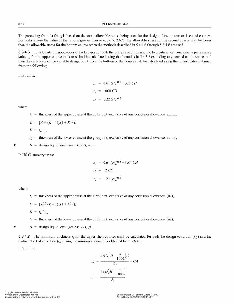
5-16 API STANDARD 650
•
•
Copyright AmProvided by No reproduc
--
The preceding formula for t2 is based on the same allowable stress being used for the design of the bottom and second courses.For tanks where the value of the ratio is greater than or equal to 2.625, the allowable stress for the second course may be lowerthan the allowable stress for the bottom course when the methods described in 5.6.4.6 through 5.6.4.8 are used.
5.6.4.6 To calculate the upper-course thicknesses for both the design condition and the hydrostatic test condition, a preliminaryvalue tu for the upper-course thickness shall be calculated using the formulas in 5.6.3.2 excluding any corrosion allowance, andthen the distance x of the variable design point from the bottom of the course shall be calculated using the lowest value obtainedfrom the following:
In SI units:
x1 = 0.61 (rtu)0.5 + 320 CH
x2 = 1000 CH
x3 = 1.22 (rtu)0.5
where
tu = thickness of the upper course at the girth joint, exclusive of any corrosion allowance, in mm,
C = [K0.5 (K – 1)]/(1 + K1.5),
K = tL / tu,
tL = thickness of the lower course at the girth joint, exclusive of any corrosion allowance, in mm,
H = design liquid level (see 5.6.3.2), in m.
In US Customary units:
x1 = 0.61 (rtu)0.5 + 3.84 CH
x2 = 12 CH
x3 = 1.22 (rtu)0.5
where
tu = thickness of the upper course at the girth joint, exclusive of any corrosion allowance, (in.),
C = [K0.5 (K – 1)]/(1 + K1.5),
K = tL / tu,
tL = thickness of the lower course at the girth joint, exclusive of any corrosion allowance, (in.),
H = design liquid level (see 5.6.3.2), (ft).
5.6.4.7 The minimum thickness tx for the upper shell courses shall be calculated for both the design condition (tdx) and thehydrostatic test condition (ttx) using the minimum value of x obtained from 5.6.4.6:
In SI units:
tdx
4.9D H x1000------------–⎝ ⎠
⎛ ⎞G
Sd-------------------------------------------- CA+=
ttx
4.9D H x1000------------–⎝ ⎠
⎛ ⎞
St----------------------------------------=
``,,,,,,`,,`,`,`,``,,````,,``-`-`,,`,,`,`,,`---
erican Petroleum Institute IHS under license with API Licensee=Bazan Oil Refineries Ltd/5957352001
Not for Resale, 02/18/2008 23:53:18 MSTtion or networking permitted without license from IHS

WELDED STEEL TANKS FOR OIL STORAGE 5-17
07
•
•
07
Copyright AmericaProvided by IHS uNo reproduction o
In US Customary units:
5.6.4.8 The steps described in 5.6.4.6 and 5.6.4.7 shall be repeated using the calculated value of tx as tu until there is little dif-ference between the calculated values of tx in succession (repeating the steps twice is normally sufficient). Repeating the stepsprovides a more exact location of the design point for the course under consideration and, consequently, a more accurate shellthickness.
5.6.4.9 The step-by-step calculations in Appendix K illustrate an application of the variable-design-point method to a tank witha diameter of 85 m (280 ft) and a height of 19.2 m (64 ft) to determine shell-plate thicknesses for the first three courses for thehydrostatic test condition only.
5.6.5 Calculation of Thickness by Elastic AnalysisFor tanks where L/H is greater than 1000/6 (2 in US Customary units), the selection of shell thicknesses shall be based on an elas-tic analysis that shows the calculated circumferential shell stresses to be below the allowable stresses given in Table 5-2. Theboundary conditions for the analysis shall assume a fully plastic moment caused by yielding of the plate beneath the shell andzero radial growth.
5.7 SHELL OPENINGS5.7.1 General
5.7.1.1 The following requirements for shell openings are intended to restrict the use of appurtenances to those providing forattachment to the shell by welding. See Figure 5-6.
5.7.1.2 The shell opening designs described in this Standard are required, except for alternative designs allowed in 5.7.1.8.
5.7.1.3 Flush-type cleanout fittings and flush-type shell connections shall conform to the designs specified in 5.7.7 and 5.7.8.
5.7.1.4 When a size intermediate to the sizes listed in Tables 5-3 through 5-14 is specified by the Purchaser, the constructiondetails and reinforcements shall conform to the next larger opening listed in the tables. The size of the opening or tank connectionshall not be larger than the maximum size given in the appropriate table.
5.7.1.5 Openings near the bottom of a tank shell will tend to rotate with vertical bending of the shell under hydrostatic loading.Shell openings in this area that have attached piping or other external loads shall be reinforced not only for the static condition butalso for any loads imposed on the shell connections by the restraint of the attached piping to the shell rotation. The external loadsshall be minimized, or the shell connections shall be relocated outside the rotation area. Appendix P provides a method for evalu-ating openings that conform to Table 5-6.
5.7.1.6 Sheared or oxygen-cut surfaces on manhole necks, nozzle necks, reinforcing plates, and shell-plate openings shall bemade uniform and smooth, with the corners rounded except where the surfaces are fully covered by attachment welds.
5.7.1.7 The periphery of the insert plates shall have a 1:4 tapered transition to the thickness of the adjacent shell plates.
5.7.1.8 With the approval of the Purchaser, the shape and dimensions of the shell reinforcing plates, illustrated in Figures 5-7A,5-7B, and 5-8 and dimensioned in the related tables, may be altered as long as the thickness, length, and width dimensions of theproposed shapes meet the area, welding, and spacing requirements outlined in 5.7.2 and 5.7.3. Reinforcement and welding ofshell openings that comply with API Std 620 are acceptable alternatives. This statement of permissible alternatives of shell open-ing reinforcement does not apply to flush-type cleanout fittings and flush-type shell connections.
5.7.1.9 The flange facing shall be suitable for the gasket and bolting employed. Gaskets shall be selected to meet the serviceenvironment so that the required seating load is compatible with the flange rating and facing, the strength of the flange, and itsbolting (see 4.9).
tdx
2.6D H x12------–⎝ ⎠
⎛ ⎞G
Sd-------------------------------------- CA+=
ttx
2.6D H x12------–⎝ ⎠
⎛ ⎞
St----------------------------------=
--``,,,,,,`,,`,`,`,``,,````,,``-`-`,,`,,`,`,,`---
n Petroleum Institute nder license with API Licensee=Bazan Oil Refineries Ltd/5957352001
Not for Resale, 02/18/2008 23:53:18 MSTr networking permitted without license from IHS
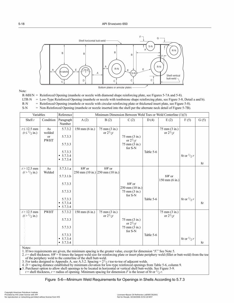
5-18 API STANDARD 650
Copyright AmProvided by No reproduc
Figure 5-6—Minimum Weld Requirements for Openings in Shells According to 5.7.3
R-NR-N
R-N
S-N
B B
A
C
R-MH/NE LTR-N
A
D
BB
A
C C
ES-N
E
C
A
F
Shell verticalbutt-weld
Bottom plates or annular plates
GF
Shell horizontal butt-weld
Note:R-MH/N = Reinforced Opening (manhole or nozzle with diamond shape reinforcing plate, see Figures 5-7A and 5-8).LTR-N = Low-Type Reinforced Opening (manhole or nozzle with tombstone shape reinforcing plate, see Figure 5-8, Detail a and b).R-N = Reinforced Opening (manhole or nozzle with circular reinforcing plate or thickened insert plate, see Figure 5-8).S-N = Non-Reinforced Opening (manhole or nozzle inserted into the shell per the alternate neck detail of Figure 5-7B).
Variables Reference Minimum Dimension Between Weld Toes or Weld Centerline (1)(3)Shell t Condition Paragraph
NumberA (2) B (2) C (2) D (4) E (2) F (5) G (5)
t ≤ 12.5 mm(t ≤ 1/2 in.)
As welded
or PWHT
5.7.3.2
5.7.3.3
5.7.3.3
5.7.3.3• 5.7.3.4• 5.7.3.4
150 mm (6 in.) 75 mm (3 in.)or 21/2t
75 mm (3 in.)or 21/2t
75 mm (3 in.)for S-N
Table 5-6
75 mm (3 in.)or 21/2t
8t or 1/2 r
8tt > 12.5 mm(t > 1/2 in.)
AsWelded
5.7.3.1.a
5.7.3.1.b
5.7.3.3
5.7.3.3
5.7.3.3• 5.7.3.4• 5.7.3.4
8W or250 mm (10 in.)
8W or250 mm (10 in.)
8W or250 mm (10 in.)75 mm (3 in.)
for S-NTable 5-6
8W or150 mm (6 in.)
8t or 1/2 r8t
t > 12.5 mm(t > 1/2 in.)
PWHT 5.7.3.2
5.7.3.3
5.7.3.3
5.7.3.3• 5.7.3.4• 5.7.3.4
150 mm (6 in.) 75 mm (3 in.)or 21/2t
75 mm (3 in.)or 21/2t
75 mm (3 in.)for S-N
Table 5-6
75 mm (3 in.)or 21/2t
8t or 1/2 r8t
Notes:1. If two requirements are given, the minimum spacing is the greater value, except for dimension “F.” See Note 5.2. t = shell thickness. 8W = 8 times the largest weld size for reinforcing plate or insert plate periphery weld (fillet or butt-weld) from the toe
of the periphery weld to the centerline of the shell butt-weld.3. For tanks designed to Appendix A, see A.5.2. Spacing = 21/2 t toe-to-toe of adjacent welds.4. D = spacing distance established by minimum elevation for low-type reinforced openings from Table 5-6, column 9.5. Purchaser option to allow shell openings to be located in horizontal or vertical shell butt-welds. See Figure 5-9.
t = shell thickness, r = radius of opening. Minimum spacing for dimension F is the lesser of 8t or 1/2 r.•
--``,,,,,,`,,`,`,`,``,,````,,``-`-`,,`,,`,`,,`---
erican Petroleum Institute IHS under license with API Licensee=Bazan Oil Refineries Ltd/5957352001
Not for Resale, 02/18/2008 23:53:18 MSTtion or networking permitted without license from IHS

WELDED STEEL TANKS FOR OIL STORAGE 5-19
07
Copyright AmericaProvided by IHS uNo reproduction o
--``,,,,,,`,,`,`,`,``,,````,,``-`-`,,`,,`,`,,`---
Table 5-3—Thickness of Shell Manhole Cover Plate and Bolting Flange
Column 1 Column 2 Column 3 Column 4 Column 5 Column 6 Column 7 Column 8 Column 9 Column 10
Max. Design Liquid Level
m (ft)H
Equivalent Pressurea
kPa (lbf/in.2)
Minimum Thickness of Cover Plateb (tc) Minimum Thickness of Bolting Flange After Finishingb (tf)
500 mm (20 in.)Manhole
600 mm (24 in.)Manhole
750 mm (30 in.)Manhole
900 mm (36 in.)Manhole
500 mm (20 in.)Manhole
600 mm (24 in.)Manhole
750 mm (30 in.)Manhole
900 mm (36 in.)Manhole
5.2 (17.1) 51 (7.4) 8 (5/16) 10 (3/8) 11 (7/16) 13 (1/2) 6 (1/4) 6 (1/4) 8 (5/16) 10 (3/8)
6.7 (21.9) 66 (9.5) 10 (3/8) 11 (7/16) 13 (1/2) 14 (9/16) 6 (1/4) 8 (5/16) 10 (3/8) 11 (7/16)
8.0 (26.1) 78 (11.3) 10 (3/8) 11 (7/16) 14 (9/16) 16 (5/8) 6 (1/4) 8 (5/16) 11 (7/16) 13 (1/2)
9.9 (32.6) 97 (14.1) 11 (7/16) 13 (1/2) 16 (5/8) 18 (11/16) 8 (5/16) 10 (3/8) 13 (1/2) 14 (9/16)
11.1 (36.5) 109 (15.8) 13 (1/2) 14 (9/16) 16 (5/8) 19 (3/4) 10 (3/8) 11 (7/16) 13 (1/2) 16 (5/8)
13.4 (43.9) 131 (19) 13 (1/2) 14 (9/16) 18 (11/16) 21 (13/16) 10 (3/8) 11 (7/16) 14 (9/16) 18 (11/16)
16.1 (52.9) 158 (22.9) 14 (9/16) 16 (5/8) 19 (3/4) 22 (7/8) 11 (7/16) 13 (1/2) 16 (5/8) 19 (3/4)
18.6 (61.0) 182 (26.4) 16 (5/8) 18 (11/16) 21 (13/16) 24 (15/16) 13 (1/2) 14 (9/16) 18 (11/16) 21 (13/16)
22.9 (75.1) 224 (32.5) 18 (11/16) 19 (3/4) 24 (15/16) 25 (1) 13 (1/2) 14 (9/16) 18 (11/16) 24 (15/16)
aEquivalent pressure is based on water loading.bFor addition of corrosion allowance, see 5.7.5.2.cCover Plate and Flange thickness given can be used on Manholes dimensioned to ID or OD.Note: See Figure 5-7A.
Table 5-4—Dimensions for Shell Manhole Neck Thickness
Thickness of Shell and Manhole Reinforcing Platea t and T
Minimum Neck Thicknessb,c tn mm (in.)
For Manhole Diameter500 mm (20 in.)
For Manhole Diameter600 mm (24 in.)
For Manhole Diameter750 mm (30 in.)
For Manhole Diameter900 mm (36 in.)
5 (3/16) 5 (3/16) 5 (3/16) 5 (3/16) 5 (3/16)6 (1/4) 6 (1/4) 6 (1/4) 6 (1/4) 6 (1/4)8 (5/16) 6 (1/4) 6 (1/4) 8 (5/16) 8 (5/16)
10 (3/8) 6 (1/4) 6 (1/4) 8 (5/16) 10 (3/8)11 (7/16) 6 (1/4) 6 (1/4) 8 (5/16) 10 (3/8)12.5 (1/2) 6 (1/4) 6 (1/4) 8 (5/16) 10 (3/8)14 (9/16) 6 (1/4) 6 (1/4) 8 (5/16) 10 (3/8)16 (5/8) 6 (1/4) 6 (1/4) 8 (5/16) 10 (3/8)18 (11/16) 6 (1/4) 6 (1/4) 8 (5/16) 10 (3/8)19 (3/4) 6 (1/4) 6 (1/4) 8 (5/16) 10 (3/8)21 (13/16) 8 (5/16) 6 (1/4) 8 (5/16) 10 (3/8)22 (7/8) 10 (3/8) 8 (5/16) 8 (5/16) 10 (3/8)24 (15/16) 11 (7/16) 11 (7/16) 11 (7/16) 11 (7/16)25 (1) 11 (7/16) 11 (7/16) 11 (7/16) 11 (7/16)27 (11/16) 11 (7/16) 11 (7/16) 11 (7/16) 11 (7/16)28 (11/8) 13 (1/2) 13 (1/2) 13 (1/2) 13 (1/2)30 (13/16) 14 (9/16) 14 (9/16) 14 (9/16) 14 (9/16)32 (11/4) 16 (5/8) 14 (9/16) 14 (9/16) 14 (9/16)33 (15/16) 16 (5/8) 16 (5/8) 16 (5/8) 16 (5/8)34 (13/8) 17 (11/16) 16 (5/8) 16 (5/8) 16 (5/8)36 (17/16) 17 (11/16) 17 (11/16) 17 (11/16) 17 (11/16)40 (11/2) 19 (3/4) 19 (3/4) 19 (3/4) 19 (3/4)
aIf a shell plate thicker than required is used for the product and hydrostatic loading (see 5.6), the excess shell-plate thickness, within a vertical distance both aboveand below the centerline of the hole in the tank shell plate equal to the vertical dimension of the hole in the tank shell plate, may be considered as reinforcement,and the thickness T of the manhole reinforcing plate may be decreased accordingly. In such cases, the reinforcement and the attachment welding shall conform tothe design limits for reinforcement of shell openings specified in 5.7.2.bReinforcement shall be added if the neck thickness is less than that shown in the column. The minimum neck thickness shall be the thickness of the shell plate orthe allowable finished thickness of the bolting flange (see Table 5-3), whichever is thinner, but in no case shall the neck in a built-up manhole be thinner than thethicknesses given. If the neck thickness on a built-up manhole is greater than the required minimum, the manhole reinforcing plate may be decreased accordinglywithin the limits specified in 5.7.2.cFor addition of corrosion allowance, see 5.7.5.2.
n Petroleum Institute nder license with API Licensee=Bazan Oil Refineries Ltd/5957352001
Not for Resale, 02/18/2008 23:53:18 MSTr networking permitted without license from IHS

5-20 API STANDARD 650
Copyright AmProvided by No reproduc
Figure 5-7A—Shell Manhole
500 mm (20") manhole: 635 mm (253/8") OD × 500 mm (20") ID × 3 mm (1/8") thickness600 mm (24") manhole: 735 mm (293/8") OD × 600 mm (24") ID × 3 mm (1/8") thickness750 mm (30") manhole: 885 mm (353/8") OD × 750 mm (30") ID × 3 mm (1/8") thickness900 mm (36") manhole: 1035 mm (413/8") OD × 900 mm (36") ID × 3 mm (1/8") thickness
Gasket (see Note 1):
Reinforcing padshall be shapedto suit tankcurvature
Rounded corners(150 mm [6"] minimum radius)
Arc dimension = W/2 500 mm (20") and 600 mm (24") manhole: 750 mm (30")750 mm (30") manhole: 900 mm (36")
900 mm (36") manhole: 1050 mm (42")(Increase as necessary for clearance)
t
T
Seedetails
125 mm (5") minimum32 mm (11/4")
500 mm (20") and 600 mm (24") shell manholes: twenty-eight 20 mm-diameter (3/4") bolts in 24 mm (7/8") holes750 mm (30") and 900 mm (36") shell manholes: forty-two 20 mm-diameter (3/4") bolts in 24 mm (7/8") holes(Bolt holes shall straddle the flange vertical centerline.)
(See Figure 3-7B)
Alternativecircular shape
(see Note 8)
1
1
230 mm(9")
10 mm-diameter(3/8") rod
75 mm(3")
150 mm(6")
OD
DR
DO/2 (see
Note 8)
CL CL
Db Dp
Dc
6 mm (1/4")
C L
One 6 mm (1/4") telltalehole in reinforcing plate,
on horizontalcenterline
L
Sym
met
rical
abo
ut
DR/2 (see
Note 8)L
SeeFigure3-7B
(SeeNote 7)
See Note 2
(seeNote 4)
Roundedcorner
Manhole OD
Uniform, smooth surface
tn 6 mm(1/4")
Detail a
See Note 2
tn (seeNote 4)
t f (see Note 3)
Manhole OD
Roundedcorners
SeeNote 5
Detail b
t f (see Note 3)
tc
t f
tn
(seeNote 8)
Notes:1. Gasket material shall be specified by the Purchaser. See 5.7.5.4. 2. The gasketed face shall be machine-finished to provide a minimum
gasket-bearing width of 20 mm (3/4 in.).3. See Table 5-3.4. See Table 5-4.5. The size of the weld shall equal the thickness of the thinner member
joined.6. The shell nozzles shown in Figure 5-8 may be substituted for
manholes.
7. The minimum centerline elevations allowed by Table 5-6 andFigure 5-6 may be used when approved by the Purchaser.
8. For dimensions for OD, DR, Do, L, and W, see Table 5-6, Columns2, 4, 5, and 6. For Dimension DP see Table 5-7 Column 3.
9. At the option of the Manufacturer, the manhole ID may be set tothe OD dimension listed in Table 5-6, column 2. Reinforcementarea and weld spacing must meet 5.7.2 and 5.7.3 requirementsrespectively.
••
--``,,,,,,`,,`,`,`,``,,````,,``-`-`,,`,,`,`,,`---
erican Petroleum Institute IHS under license with API Licensee=Bazan Oil Refineries Ltd/5957352001
Not for Resale, 02/18/2008 23:53:18 MSTtion or networking permitted without license from IHS

WELDED STEEL TANKS FOR OIL STORAGE 5-21
Copyright AmericaProvided by IHS uNo reproduction o
DO (min)
L and W or DO
(see Table 5-6)
OD of insert plate
(SeeNote 2)
C L
JJ
Ne
ck b
eve
l sh
ou
ld b
e a
bo
ut
10
de
gre
es
Ro
un
d a
nd
grin
d c
orn
er
(Se
e T
ab
le 5
-7)
(Se
e T
ab
les 5
-6 a
nd
5-7
)
C L
T +
t(m
in) Sh
ell(See
Note 2)DO (min)
(Se
e N
ote
3)
A
t (m
in)
45
º
1/3
(T +
t)
min
(SeeNote 2)
1/3
(t +
T)
min
(Se
e T
ab
le 5
-7)
T +
t(m
in)
A
Bo
tto
m
45
º
[10
mm
(3/8
") m
axim
um
]
[10
mm
(3/8
") m
axim
um
]
Ra
dio
gra
ph
(se
e 8
.1.2
.2,
Ite
m d
)
T +
t(m
in)
1:4
be
ve
l
Alte
rna
tive
be
ve
l
Ra
dio
gra
ph
(se
e 8
.1.2
.2,
Ite
m d
)
45
º
C LC L
INS
ER
T-T
YP
E R
EIN
FO
RC
EM
EN
T F
OR
MA
NH
OL
ES
AN
D N
OZ
ZL
ES
A
Ra
dio
gra
ph
(se
e 8
.1.2
.2,
Ite
m d
)
tt
1.5
mm
(1 /16
")1.
5 m
m (
1 /16")
t1
:4 b
eve
l
1:4
be
ve
l
(See Tables 5-6and 5-7)
(See Note 1)
Manufacturer’s standard(15 degrees minimum,35 degrees maximum)
Tt
A
Ro
un
d c
orn
er
if w
eld
<T
(Se
e T
ab
le 5
-7)
(Se
e T
ab
le 5
-7)
A[1
0 m
m (
3/8
") m
axim
um
]
NO
ZZ
LEJ
J
(See Note 1)
Manufacturer’s standard(15 degrees minimum,35 degrees maximum)
L and W (Table 5-6) or DO
Tt
T o
r t
[40
mm
(1
1/2
") m
axim
um
]
A
1.5
mm
(1/1
6")
T o
r t
[40
mm
(1
1/2
") m
axim
um
]
1.5
mm
(1/1
6")
Ro
un
d c
orn
er
if w
eld
<T
(Se
e T
ab
les
5-6
an
d 5
-7)
Ro
un
d a
nd
grin
d
Ne
ck b
eve
l sh
ou
ld b
ea
bo
ut
10
de
gre
es
(Se
e T
ab
le 5
-7)
MA
NH
OL
E O
R N
OZ
ZL
E
Alte
rna
tive
ne
ck d
eta
il
t n
t n
t n
1.5
mm
(1 /16
")
Nozzle
Nozzle
Not
es:
1.Se
e Ta
ble
5-7,
Col
umn
3, f
or t
he s
hell
cuto
ut,
whi
ch s
hall
not
be le
ssth
an th
e ou
tsid
e di
amet
er o
f the
nec
k pl
us 1
3 m
m (1
/ 2) i
n.2.
See
5.7.
3 fo
r min
imum
spa
cing
of w
elds
at o
peni
ng c
onne
ctio
ns.
3.Th
e w
eld
size
sha
ll be
eith
er A
(fro
m T
able
5-7
, bas
ed o
n t)
or t n
(min
imum
neck
thic
knes
s fro
m T
able
s 5-
4, 5
-6, a
nd 5
-7),
whi
chev
er is
gre
ater
.
4.O
ther
per
mis
sibl
e in
sert
deta
ils a
re s
how
n in
Fig
ure
3-8
of A
PI S
td 6
20.
The
rein
forc
emen
t are
a sh
all c
onfo
rm to
5.7
.2.
5.D
imen
sion
s an
d w
eld
size
s th
at a
re n
ot s
how
n ar
e th
e sa
me
as th
ose
give
n in
Fig
ure
5-7A
and
Tab
les
5-4
– 5-
8.6.
Det
ails
of w
eldi
ng b
evel
s m
ay v
ary
from
thos
e sh
own
if ag
reed
to b
y th
ePu
rcha
ser.
•
Figu
re5-
7B—
Det
ails
of S
hell
Man
hole
s an
d N
ozzl
es
n Petroleum Institute nder license with API Licensee=Bazan Oil Refineries Ltd/5957352001
Not for Resale, 02/18/2008 23:53:18 MSTr networking permitted without license from IHS
--``,,,,,,`,,`,`,`,``,,````,,``-`-`,,`,,`,`,,`---

5-22 API STANDARD 650
07
Copyright AmProvided by No reproduc
Figure 5-8—Shell Nozzles (See Tables 5-6, 5-7, and 5-8)
REINFORCING PLATE
REGULAR-TYPE FLANGED NOZZLES, NPS 3 OR LARGER(Bolt holes shall straddle flange centerlines)
Diamond Circular
Single Flange Special Flange
Detail b
One 6 mm (1/4") telltale holein reinforcing plate,
on horizontal centerline
Bend reinforcing plate toradius of tank shell
Alternative shapefor low-type nozzles
See Detail a or b forbottom edge
(See Figure 5-7B) (See Figure 5-7B)(See Figure 5-7B)
(See Figure 5-7B)
Arc distance
1
1
Tank bottom
Victaulic grooveor threads
(See Note 1) (See Note 1)
(See Note 1)
(See Note 5)60º
t /2 [6 mm (1/4") minimum]
C
Chip
DO
DP
DRDR
W
L
DP
DR/2
DR/2
J J
t
TQ
OD
BB
HN
OD
J J
t
TQ Q
J t
TQ
OD
B
Nozzle CL
Double Flange
T T
t t
L
Detail a
LOW-TYPE FLANGED NOZZLES, NPS 3 OR LARGER(Bolt holes shall straddle flange centerlines)
Notes:1. See 5.1.5.7 for information on the size of welds.2. See 5.8.9 for information on the couplings used in shell nozzles.3. Nozzles NPS 3 or larger require reinforcement.
4. Details of welding bevels may vary from those shown if agreed toby the Purchaser.
5. Shop weld not attached to bottom plate.6. See 5.7.6.2 for information on supplying nozzles flush or with an
internal projection.
•
--``,,,,,,`,,`,`,`,``,,````,,``-`-`,,`,,`,`,,`---
erican Petroleum Institute IHS under license with API Licensee=Bazan Oil Refineries Ltd/5957352001
Not for Resale, 02/18/2008 23:53:18 MSTtion or networking permitted without license from IHS

WELDED STEEL TANKS FOR OIL STORAGE 5-23
•
07
•
Copyright AmericaProvided by IHS uNo reproduction o
--``,,,,,,`,,`,`,`,``,,````,,``-`-`,,`,,`,`,,`---
5.7.2 Reinforcement and Welding
5.7.2.1 Openings in tank shells larger than required to accommodate a NPS 2 flanged or threaded nozzle shall be reinforced.The minimum cross-sectional area of the required reinforcement shall not be less than the product of the vertical diameter of thehole cut in the shell and the nominal plate thickness, but when calculations are made for the maximum required thickness consid-ering all design and hydrostatic test load conditions, the required thickness may be used in lieu of the nominal plate thickness. Thecross-sectional area of the reinforcement shall be measured vertically, coincident with the diameter of the opening.
5.7.2.2 The only shell openings that may utilize welds having less than full penetration through the shell are those that do notrequire reinforcement and those that utilize a thickened insert plate as shown in Figures 5-7B and 5-8. However, any openingslisted in Table 3 of the Data Sheet that are marked “yes” under “Full Penetration on Openings” shall utilize welds that fully pene-trate the shell and the reinforcement, if used.
5.7.2.3 Except for flush-type openings and connections, all effective reinforcements shall be made within a distance above andbelow the centerline of the shell opening equal to the vertical dimension of the hole in the tank shell plate. Reinforcement may beprovided by any one or any combination of the following:
a. The attachment flange of the fitting.b. The reinforcing plate. Reinforcing plates for manholes, nozzles, and other attachments shall be of the same nominal composi-tion (i.e., same ASME P-number and Group Number) as the tank part to which they are attached, unless approved otherwise bythe Purchaser.
Figure 5-8—Shell Nozzles (continued)
Table 5-5—Dimensions for Bolt Circle Diameter Db and Cover Plate Diameter Dc for Shell Manholes
Column 1 Column 2 Column 3Manhole Diameter OD
mm (in.)Bolt Circle Diameter Db
mm (in.)Cover Plate Diameter Dc
mm (in.)500 (20) 656 (261/4) 720 (283/4)600 (24) 756 (301/4) 820 (323/4)750 (30) 906 (361/4) 970 (383/4)900 (36) 1056 (421/4) 1120 (443/4)
Note: See Figure 5-7A.
DimensionA = size of fillet weld A(see Note 1
Shell Shell Shell ShellHN C
Bottom Bottom Bottom Bottom
t
Type a Type b Type c Type d
45º
CL
A
t
J
0
t t10 mm (3/8")maximum
10 mm (3/8")maximum
11/4 tmin
(see Note 2) 11/4 tmin
(see Note 2)
(see Note 1)
A(see Note 1)
1.5 mm (1/16")
COUPLINGS AND FLANGED FITTINGS, NPS 3/4 THROUGH NPS 2 (SEE NOTE 3)
A
Lo
w t
yp
e
Re
gu
lar
Notes: (continued)7. See Table 5-7, Column 6.8. tmin shall be 19 mm (3/4 in.) or the thickness of either part joined by the fillet weld, whichever is less.9. The construction details apply to unreinforced threaded, non-threaded, and flanged nozzles.
n Petroleum Institute nder license with API Licensee=Bazan Oil Refineries Ltd/5957352001
Not for Resale, 02/18/2008 23:53:18 MSTr networking permitted without license from IHS

5-24 API STANDARD 650
•
Copyright AmProvided by No reproduc
--``,,,,,,`,,`,`,`,``,,````,,``-`-`,,`,,`,`,,`---
Table 5-6—Dimensions for Shell Nozzles (mm [in.])
Column 1 Column 2 Column 3 Column 4 Column 5 Column 6 Column 7c Column 8c Column 9c
NPS(Size of Nozzle)
Outside Diameter of
PipeOD
Nominal Thickness of
Flanged Nozzle Pipe Walla
tn
Diameter of Hole in
Reinforcing PlateDR
Length of Side of Reinforcing
Plateb or DiameterL = Do
Width of Reinforcing
PlateW
Minimum Distance from
Shell-to-Flange Face
J
Minimum Distance from Bottom of Tank to Center of Nozzle
Regular Typed
HNLow Type
CFlanged Fittings
48 1219.2 (48) e 1222 (481/8) 2455 (963/4) 2970 (117) 400 (16) 1325 (52) 1230 (483/8)46 1168.4 (46) e 1172 (461/8) 2355 (923/4) 2845 (112) 400 (16) 1275 (50) 1180 (463/8)44 1117.6 (44) e 1121 (441/8) 2255 (883/4) 2725 (1071/4) 375 (15) 1225 (48) 1125 (443/8)42 1066.8 (42) e 1070 (421/8) 2155 (843/4) 2605 (1021/2) 375 (15) 1175 (46) 1075 (423/8)40 1016 (40) e 1019 (401/8) 2050 (803/4) 2485 (973/4) 375 (15) 1125 (44) 1025 (403/8)38 965.2 (38) e 968 (381/8) 1950 (763/4) 2355 (923/4) 350 (14) 1075 (42) 975 (383/8)36 914.4 (36) e 918 (361/8) 1850 (723/4) 2235 (88) 350 (14) 1025 (40) 925 (363/8)34 863.6 (34) e 867 (341/8) 1745 (683/4) 2115 (831/4) 325 (13) 975 (38) 875 (343/8)32 812.8 (32) e 816 (321/8) 1645 (643/4) 1995 (781/2) 325 (13) 925 (36) 820 (323/8)30 762.0 (30) e 765 (301/8) 1545 (603/4) 1865 (731/2) 300 (12) 875 (34) 770 (303/8)28 711.2 (28) e 714 (281/8) 1440 (563/4) 1745 (683/4) 300 (12) 825 (32) 720 (283/8)26 660.4 (26) e 664 (261/8) 1340 (523/4) 1625 (64) 300 (12) 750 (30) 670 (263/8)24 609.6 (24) 12.7 (0.50) 613 (241/8) 1255 (491/2) 1525 (60) 300 (12) 700 (28) 630 (243/4)22 558.8 (22) 12.7 (0.50) 562 (221/8) 1155 (451/2) 1405 (551/4) 275 (11) 650 (26) 580 (223/4)20 508.0 (20) 12.7 (0.50) 511 (201/8) 1055 (411/2) 1285 (501/2) 275 (11) 600 (24) 525 (203/4)18 457.2 (18) 12.7 (0.50) 460 (181/8) 950 (371/2) 1160 (453/4) 250 (10) 550 (22) 475 (183/4)16 406.4 (16) 12.7 (0.50) 410 (161/8) 850 (331/2) 1035 (403/4) 250 (10) 500 (20) 425 (163/4)14 355.6 (14) 12.7 (0.50) 359 (141/8) 750 (291/2) 915 (36) 250 (10) 450 (18) 375 (143/4)12 323.8 (123/4) 12.7 (0.50) 327 (127/8) 685 (27) 840 (33) 225 (9) 425 (17) 345 (131/2)10 273.0 (103/4) 12.7 (0.50) 276 (107/8) 585 (23) 720 (281/4) 225 (9) 375 (15) 290 (111/2)8 219.1 (85/8) 12.7 (0.50) 222 (83/4) 485 (19) 590 (231/4) 200 (8) 325 (13) 240 (91/2)6 168.3 (65/8) 10.97 (0.432) 171 (63/4) 400 (153/4) 495 (191/2) 200 (8) 275 (11) 200 (77/8)4 114.3 (41/2) 8.56 (0.337) 117 (45/8) 305 (12) 385 (151/4) 175 (7) 225 (9) 150 (6)3 88.9 (31/2) 7.62 (0.300) 92 (35/8) 265 (101/2) 345 (131/2) 175 (7) 200 (8) 135 (51/4)2f 60.3 (23/8) 5.54 (0.218) 63 (21/2) — — 150 (6) 175 (7) h11/2f 48.3 (1.90) 5.08 (0.200) 51 (2) — — 150 (6) 150 (6) h
1f 33.4 (1.315) 6.35 (0.250) — — — 150 (6) 150 (6) h 3/4f 26.7 (1.05) 5.54 (0.218) — — — 150 (6) 150 (6) h
Threaded and Socket-Welded Couplings3g 108.0 (4.250) Coupling 111.1 (4 3/8) 285 (111/4) 360 (141/4) — 225 (9) 145 (55/8)2f 76.2 (3.000) Coupling 79.4 (31/8) — — — 175 (7) h11/2f 63.5 (2.500) Coupling 66.7 (25/8) — — — 150 (6) h1f 44.5 (1.750) Coupling 47.6 (17/8) — — — 125 (5) h
3/4f 35.0 (1.375) Coupling 38.1 (11/2) — — — 100 (4) h
aFor extra-strong pipe, see ASTM A 53 or A 106 for other wall thicknesses; however, piping material must conform to 4.5.bThe width of the shell plate shall be sufficient to contain the reinforcing plate and to provide clearance from the girth joint of the shell course.cUnless otherwise specified by the Purchaser, the nozzle shall be located at the minimum distance but shall also meet the weld spacing requirementsof 5.7.3.dThe HN dimensions given in this table are for Appendix A tank designs only; see 5.7.3 to determine minimum HN for basic tank designs.eSee Table 5-7, Column 2.fFlanged nozzles and couplings in pipe sizes NPS 2 or smaller do not require reinforcing plates. DR will be the diameter of the hole in the shellplate, and Weld A will be as specified in Table 5-7, Column 6. Reinforcing plates may be used if the construction details comply with reinforcednozzle details.gA coupling in an NPS 3 requires reinforcement.hSee 5.7.3.Note: See Figure 5-8.
erican Petroleum Institute IHS under license with API Licensee=Bazan Oil Refineries Ltd/5957352001
Not for Resale, 02/18/2008 23:53:18 MSTtion or networking permitted without license from IHS
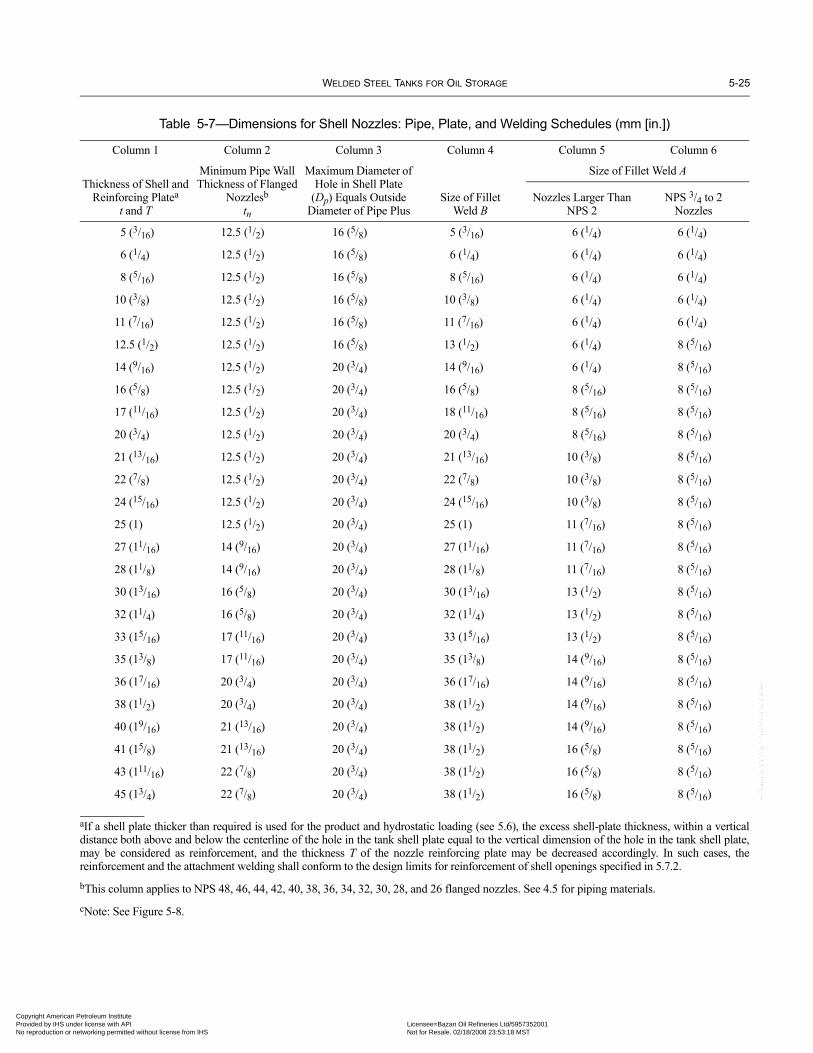
WELDED STEEL TANKS FOR OIL STORAGE 5-25
Copyright AmericaProvided by IHS uNo reproduction o
--``,,,,,,`,,`,`,`,``,,````,,``-`-`,,`,,`,`,,`---
Table 5-7—Dimensions for Shell Nozzles: Pipe, Plate, and Welding Schedules (mm [in.])
Column 1 Column 2 Column 3 Column 4 Column 5 Column 6
Thickness of Shell and Reinforcing Platea
t and T
Minimum Pipe Wall Thickness of Flanged
Nozzlesb
tn
Maximum Diameter of Hole in Shell Plate
(Dp) Equals Outside Diameter of Pipe Plus
Size of FilletWeld B
Size of Fillet Weld A
Nozzles Larger Than NPS 2
NPS 3/4 to 2 Nozzles
5 (3/16) 12.5 (1/2) 16 (5/8) 5 (3/16) 6 (1/4) 6 (1/4)
6 (1/4) 12.5 (1/2) 16 (5/8) 6 (1/4) 6 (1/4) 6 (1/4)
8 (5/16) 12.5 (1/2) 16 (5/8) 8 (5/16) 6 (1/4) 6 (1/4)
10 (3/8) 12.5 (1/2) 16 (5/8) 10 (3/8) 6 (1/4) 6 (1/4)
11 (7/16) 12.5 (1/2) 16 (5/8) 11 (7/16) 6 (1/4) 6 (1/4)
12.5 (1/2) 12.5 (1/2) 16 (5/8) 13 (1/2) 6 (1/4) 8 (5/16)
14 (9/16) 12.5 (1/2) 20 (3/4) 14 (9/16) 6 (1/4) 8 (5/16)
16 (5/8) 12.5 (1/2) 20 (3/4) 16 (5/8) 8 (5/16) 8 (5/16)
17 (11/16) 12.5 (1/2) 20 (3/4) 18 (11/16) 8 (5/16) 8 (5/16)
20 (3/4) 12.5 (1/2) 20 (3/4) 20 (3/4) 8 (5/16) 8 (5/16)
21 (13/16) 12.5 (1/2) 20 (3/4) 21 (13/16) 10 (3/8) 8 (5/16)
22 (7/8) 12.5 (1/2) 20 (3/4) 22 (7/8) 10 (3/8) 8 (5/16)
24 (15/16) 12.5 (1/2) 20 (3/4) 24 (15/16) 10 (3/8) 8 (5/16)
25 (1) 12.5 (1/2) 20 (3/4) 25 (1) 11 (7/16) 8 (5/16)
27 (11/16) 14 (9/16) 20 (3/4) 27 (11/16) 11 (7/16) 8 (5/16)
28 (11/8) 14 (9/16) 20 (3/4) 28 (11/8) 11 (7/16) 8 (5/16)
30 (13/16) 16 (5/8) 20 (3/4) 30 (13/16) 13 (1/2) 8 (5/16)
32 (11/4) 16 (5/8) 20 (3/4) 32 (11/4) 13 (1/2) 8 (5/16)
33 (15/16) 17 (11/16) 20 (3/4) 33 (15/16) 13 (1/2) 8 (5/16)
35 (13/8) 17 (11/16) 20 (3/4) 35 (13/8) 14 (9/16) 8 (5/16)
36 (17/16) 20 (3/4) 20 (3/4) 36 (17/16) 14 (9/16) 8 (5/16)
38 (11/2) 20 (3/4) 20 (3/4) 38 (11/2) 14 (9/16) 8 (5/16)
40 (19/16) 21 (13/16) 20 (3/4) 38 (11/2) 14 (9/16) 8 (5/16)
41 (15/8) 21 (13/16) 20 (3/4) 38 (11/2) 16 (5/8) 8 (5/16)
43 (111/16) 22 (7/8) 20 (3/4) 38 (11/2) 16 (5/8) 8 (5/16)
45 (13/4) 22 (7/8) 20 (3/4) 38 (11/2) 16 (5/8) 8 (5/16)
aIf a shell plate thicker than required is used for the product and hydrostatic loading (see 5.6), the excess shell-plate thickness, within a verticaldistance both above and below the centerline of the hole in the tank shell plate equal to the vertical dimension of the hole in the tank shell plate,may be considered as reinforcement, and the thickness T of the nozzle reinforcing plate may be decreased accordingly. In such cases, thereinforcement and the attachment welding shall conform to the design limits for reinforcement of shell openings specified in 5.7.2.bThis column applies to NPS 48, 46, 44, 42, 40, 38, 36, 34, 32, 30, 28, and 26 flanged nozzles. See 4.5 for piping materials.cNote: See Figure 5-8.
n Petroleum Institute nder license with API Licensee=Bazan Oil Refineries Ltd/5957352001
Not for Resale, 02/18/2008 23:53:18 MSTr networking permitted without license from IHS

5-26 API STANDARD 650
•
Copyright AmProvided by No reproduc
Table 5-8—Dimensions for Shell Nozzle Flanges (mm [in.])
Column 1 Column 2 Column 3 Column 4 Column 5 Column 6 Column 7 Column 8 Column 9 Column 10 Column 11 Column 12
NPS (Size of Nozzle)
Minimum Thicknessof Flanged
Q
Outside Diameterof Flange
A
Diameterof Raised
FaceD
Diameterof BoltCircle
C
Numberof
Holes
Diameterof
Holes
Diameterof
Bolts
Diameter of BoreMinimum Diameter of Hub at Point of Weld
Slip-On Type: Outside
Diameter of Pipe Plus
B
Welding Neck Typea
B1
Slip-On Typeb
E
Welding-Neck Typec
E1
48 70 (23/4) 1510 (591/2) 1360 (531/2) 1420 (56) 44 42 (15/8) 38 (11/2) 6.8 (0.25) a b c
46 68 (211/16) 1460 (571/2) 1295 (51) 1365 (533/4) 40 42 (15/8) 38 (11/2) 6.6 (0.25) a b c
44 67 (25/8) 1405 (551/4) 1245 (49) 1315 (513/4) 40 42 (15/8) 38 (11/2) 6.4 (0.25) a b c
42 67 (25/8) 1345 (53) 1195 (47) 1255 (491/2) 36 42 (15/8) 38 (11/2) 6.2 (0.25) a b c
40 65 (21/2) 1290 (503/4) 1125 (441/4) 1200 (471/4) 36 42 (15/8) 38 (11/2) 6.0 (0.25) a b c
38 60 (23/8) 1240 (483/4) 1075 (421/4) 1150 (451/4) 32 42 (15/8) 38 (11/2) 6.8 (0.25) a b c
36 60 (23/8) 1170 (46) 1020 (401/4) 1085 (423/4) 32 42 (15/8) 38 (11/2) 6.6 (0.25) a b c
34 59 (25/16) 1110 (433/4) 960 (373/4) 1030 (401/2) 32 42 (15/8) 38 (11/2) 6.4 (0.25) a b c
32 57 (21/4) 1060 (413/4) 910 (353/4) 980 (381/2) 28 42 (15/8) 38 (11/2) 6.2 (0.25) a b c
30 54 (21/8) 985 (383/4) 855 (333/4) 915 (36) 28 33 (13/8) 30 (11/4) 6.0 (0.25) a b c
28 52 (21/16) 925 (361/2) 795 (311/4) 865 (34) 28 33 (13/8) 30 (11/4) 6.8 (0.25) a b c
26 50 (2) 870 (341/4) 745 (291/4) 805 (313/4) 24 33 (13/8) 30 (11/4) 6.6 (0.25) a b c
24 48 (17/8) 815 (32) 690 (271/4) 750 (291/2) 20 33 (13/8) 30 (11/4) 4.4 (0.19) a b c
22 46 (113/16) 750 (291/2) 640 (251/4) 690 (271/4) 20 33 (13/8) 30 (11/4) 5.2 (0.19) a b c
20 43 (111/16) 700 (271/2) 585 (23) 635 (25) 20 30 (11/4) 27 (11/8) 5.0 (0.19) a b c
18 40 (19/16) 635 (25) 535 (21) 580 (223/4) 16 30 (11/4) 27 (11/8) 4.8 (0.19) a b c
16 36 (17/16) 595 (231/2) 470 (181/2) 540 (211/4) 16 27 (11/8) 24 (1) 4.6 (0.19) a b c
14 35 (13/8) 535 (21) 415 (161/4) 475 (183/4) 12 27 (11/8) 24 (1) 4.4 (0.19) a b c
12 32 (11/4) 485 (19) 380 (15) 430 (17) 12 25 (1) 22 (7/8) 3.15 (0.13) a b c
10 30 (13/16) 405 (16) 325 (123/4) 360 (141/4) 12 25 (1) 22 (7/8) 2.95 (0.13) a b c
8 28 (11/8) 345 (131/2) 270 (105/8) 300 (113/4) 8 23 (7/8) 20 (3/4) 2.92 (0.10) a b c
6 25 (1) 280 (11) 216 (81/2) 240 (91/2) 8 23 (7/8) 20 (3/4) 2.72 (0.10) a b c
4 24 (15/16) 230 (9) 157 (63/16) 190 (71/2) 8 19 (3/4) 16 (5/8) 1.7 (0.06) a b c
3 24 (15/16) 190 (71/2) 127 (5) 152 (6) 4 19 (3/4) 16 (5/8) 1.1 (0.06) a b c
2 20 (3/4) 150 (6) 92 (35/8) 121 (43/4) 4 19 (3/4) 16 (5/8) 1.68 (0.07) a b c
11/2 17 (11/16) 125 (5) 73 (27/8) 98 (37/8) 4 16 (5/8) 12 (1/2) 1.74 (0.07) a b c
aB1 = inside diameter of pipe.bE = outside diameter of pipe + 2tn.cE1 = outside diameter of pipe.dCorrosion allowance, if specified, need not be added to flange and cover thicknesses complying with ASME B16.5 Class 150, ASME B16.1 Class 125, andASME B16.47 flanges.
Note: See Figure 5-8. The facing dimensions for slip-on and welding-neck flanges in NPS 11/2 through 20 and NPS 24 are identical to those specified in ASMEB16.5 for Class 150 steel flanges. The facing dimensions for flanges in NPS 30, 36, 42, and 48 are in agreement with ASME B16.1 for Class 125 cast iron flanges.The dimensions for large flanges may conform to Series B of ASME B16.47.
--``,,,,,,`,,`,`,`,``,,````,,``-`-`,,`,,`,`,,`---
erican Petroleum Institute IHS under license with API Licensee=Bazan Oil Refineries Ltd/5957352001
Not for Resale, 02/18/2008 23:53:18 MSTtion or networking permitted without license from IHS

WELDED STEEL TANKS FOR OIL STORAGE 5-27
•
Copyright AmericaProvided by IHS uNo reproduction o
Table 5-9—Dimensions for Flush-Type Cleanout Fittings (mm [in.])
Column 1 Column 2 Column 3 Column 4 Column 5 Column 6 Column 7 Column 8 Column 9 Column 10 Column 11
Height of Opening
h
Width of Opening
b
Arc Width of Shell
Reinforcing Plate
W
Upper Corner
Radius of Opening
r1
Upper Corner Radius of Shell
Reinforcing Plate
r2
Edge Distanceof Bolts
e
Flange Widtha
(Except at Bottom)
f3
Bottom Flange Width
f2
Special Bolt Spacingb
g
Numberof
Bolts
Diameterof
Bolts200 (8) 400 (16) 1170 (46) 100 (4) 360 (14) 32 (11/4) 100 (4) 90 (31/2) 80 (31/4) 22 20 (3/4)600 (24) 600 (24) 1830 (72) 300 (12) 740 (29) 40 (11/2) 100 (4) 95 (33/4) 90 (31/2) 36 20 (3/4)900 (36) 1200 (48) 2700 (106) 450c (18) 1040 (41) 40 (11/2) 115 (41/2) 120 (43/4) 110 (41/4) 46 24 (1)
1200d (48) 1200 (48) 3200 (125) 600 (24) 1310 (511/2) 40 (11/2) 115 (41/2) 125 (5) 115 (41/2) 52 24 (1)
aFor neck thicknesses greater than 40 mm (19/16 in.), increase f3 as necessary to provide a 1.5 mm (1/16 in.) clearance between the required neck-to-flange weld and the head of the bolt.bRefers to spacing at the lower corners of the cleanout-fitting flange.cFor Groups IV, IVA, V, and VI, 600 mm (24 in.).dOnly for Group I, II, III, or IIIA shell materials (see 5.7.7.2).Note: See Figure 5-12.
Table 5-10—Minimum Thickness of Cover Plate, Bolting Flange, and Bottom Reinforcing Plate for Flush-Type Cleanout Fittings (mm [in.])
Column 1 Column 2 Column 3 Column 4 Column 5 Column 6 Column 7 Column 8 Column 9 Column 10Size of Opening h × b (Height × Width)
200 × 400 (8 × 16) 600 × 600 (24 × 24) 900 × 1200 (36 × 48) 1200 × 1200 (48 × 48)Maximum
Design Liquid Level
m (ft)H
Equivalent Pressurea kPa (psi)
Thicknessof Bolting Flange and Cover Plate
tc
Thicknessof Bottom
Reinforcing Plateb
tb
Thicknessof Bolting Flange and Cover Plate
tc
Thicknessof Bottom
Reinforcing Platec
tb
Thicknessof Bolting Flange and Cover Plate
tc
Thicknessof Bottom
Reinforcing Plated
tb
Thicknessof Bolting Flange and Cover Plate
tc
Thicknessof Bottom
Reinforcing Platee
tb6.1 (20) 60 (8.7) 10 (3/8) 13 (1/2) 10 (3/8) 13 (1/2) 16 (5/8) 21 (13/16) 16 (5/8) 22 (7/8)10 (34) 98 (14.7) 10 (3/8) 13 (1/2) 13 (1/2) 13 (1/2) 19 (3/4) 25 (1) 21 (13/16) 28 (11/8)12 (41) 118 (17.8) 10 (3/8) 13 (1/2) 13 (1/2) 14 (9/16) 22 (7/8) 28 (11/8) 22 (7/8) 30 (13/16)16 (53) 157 (23) 10 (3/8) 13 (1/2) 14 (9/16) 16 (5/8) 24 (15/16) 32 (11/4) 25 (1) 33 (15/16)18 (60) 177 (26) 11 (7/16) 13 (1/2) 16 (5/8) 18 (11/16) 25 (1) 33 (15/16) 28 (11/8) 35 (13/8)20 (64) 196 (27.8) 11 (7/16) 13 (1/2) 16 (5/8) 18 (11/16) 27 (11/16) 35 (13/8) 28 (11/8) 36 (17/16)22 (72) 216 (31.2) 11 (7/16) 13 (1/2) 18 (11/16) 19 (3/4) 28 (11/8) 36 (17/16) 30 (13/16) 38 (11/2)
aEquivalent pressure is based on water loading.bMaximum of 25 mm (1 in.).cMaximum of 28 mm (11/8 in.).
dMaximum of 38 mm (11/2 in.).eMaximum of 45 mm (13/4 in.).Note: See Figure 5-12.
Table 5-11—Thicknesses and Heights of Shell Reinforcing Plates for Flush-Type Cleanout Fittings (mm [in.])
Thickness of Lowest Shell Course
t, tdamm (ft)
Maximum Design Liquid Levelc
Hm (ft)
Height of Shell Reinforcing Plate forSize of Opening h × b (Height × Width)
mm (ft)
200 × 400 (8 × 16) 600 × 600 (24 × 24) 900 × 1200 (36 × 48) 1200 × 1200 (48 × 48)
All < 22 (72) 350 (14) 915 (36) 1372 (54) 1830 (72)
Notes:aDimensions td and L may be varied within the limits defined in 5.7.7.b1200 × 1200 (48 × 48) flush-type cleanout fittings are not permitted for tanks with greater than 38 mm (11/2 in.) lowest shell course thickness.cSee 5.6.3.2.
--``,,,,,,`,,`,`,`,``,,````,,``-`-`,,`,,`,`,,`---
n Petroleum Institute nder license with API Licensee=Bazan Oil Refineries Ltd/5957352001
Not for Resale, 02/18/2008 23:53:18 MSTr networking permitted without license from IHS

5-28 API STANDARD 650
07
07
07
Copyright AmProvided by No reproduc
--``,,,,,,`,,`,`,`,``,,````,,``-`-`,,`,,`,`,,`---
c. The portion of the neck of the fitting that may be considered as reinforcement according to 5.7.2.4.d. Excess shell-plate thickness. Reinforcement may be provided by any shell-plate thickness in excess of the thickness requiredby the governing load condition within a vertical distance above and below the centerline of the hole in the shell equal to the ver-tical dimension of the hole in the tank shell plate as long as the extra shell-plate thickness is the actual plate thickness used less therequired thickness, calculated at the applicable opening, considering all load conditions and the corrosion allowance.e. The material in the nozzle neck. The strength of the material in the nozzle neck used for reinforcement should preferably be thesame as the strength of the tank shell, but lower strength material is permissible as reinforcement as long as the neck material hasminimum specified yield and tensile strengths not less than 70% and 80%, respectively, of the shell-plate minimum specifiedyield and tensile strengths. When the material strength is greater than or equal to the 70% and 80% minimum values, the area inthe neck available for reinforcement shall be reduced by the ratio of the allowable stress in the neck, using the governing stressfactors, to the allowable stress in the attached shell plate. No credit may be taken for the additional strength of any reinforcingmaterial that has a higher allowable stress than that of the shell plate. Neck material that has a yield or tensile strength less than the70% or 80% minimum values may be used, provided that no neck area is considered as effective reinforcement.
5.7.2.4 The following portions of the neck of a fitting may be considered part of the area of reinforcement, except where pro-hibited by 5.7.2.3, Item e:
a. The portion extending outward from the outside surface of the tank shell plate to a distance equal to four times the neck-wallthickness or, if the neck-wall thickness is reduced within this distance, to the point of transition.b. The portion lying within the shell-plate thickness.c. The portion extending inward from the inside surface of the tank shell plate to the distance specified in Item a.
5.7.2.5 The aggregate strength of the weld attaching a fitting to the shell plate, an intervening reinforcing plate, or both shall atleast equal the proportion of the forces passing through the entire reinforcement that is calculated to pass through the fitting.
5.7.2.6 The aggregate strength of the welds attaching any intervening reinforcing plate to the shell plate shall at least equal theproportion of the forces passing through the entire reinforcement that is calculated to pass through the reinforcing plate.
5.7.2.7 The attachment weld to the shell along the outer periphery of a reinforcing plate or proprietary connection thatlap welds to the shell shall be considered effective only for the parts lying outside the area bounded by vertical linesdrawn tangent to the shell opening; however, the outer peripheral weld shall be applied completely around the reinforce-ment. See 5.7.2.8 for allowable stresses. All of the inner peripheral weld shall be considered effective. The strength of theeffective attachment weld shall be considered as the weld’s shear resistance at the stress value given for fillet welds in5.7.2.8. The size of the outer peripheral weld shall be equal to the thickness of the shell plate or reinforcing plate, which-ever is thinner, but shall not be greater than 38 mm (11/2 in.). When low-type nozzles are used with a reinforcing plate thatextends to the tank bottom (see Figure 5-8), the size of the portion of the peripheral weld that attaches the reinforcingplate to the bottom plate shall conform to 5.1.5.7. The inner peripheral weld shall be large enough to sustain the remainderof the loading.
Table 5-12—Dimensions for Flush-Type Shell Connections (mm [in.])
Class 150 Nominal Height of Flange Size
Height of Openingh
Width of Openingb
Arc Width of Shell Reinforcing Plate
W
Upper Corner Radius of Opening
r1
Lower Corner Radius of Shell Reinforcing Plate
r2
8 200 (85/8) 200 (85/8) 950 (38) 100 (4)a 350 (14)
12 300 (123/4) 300 (123/4) 1300 (52) 150 (4)a 450 (18)
16 300 (12) 500 (20) 1600 (64) 150 (6) 450 (18)
18 300 (12) 550 (22) 1650 (66) 150 (6) 450 (18)
20 300 (12) 625 (25) 1725 (69) 150 (6) 450 (18)
24 300 (12) 900 (36) 2225 (89) 150 (6) 450 (18)
aFor circular openings, this value will be 1/2 of the ID based on the nozzle neck specified.Note: See Figure 5-14.
erican Petroleum Institute IHS under license with API Licensee=Bazan Oil Refineries Ltd/5957352001
Not for Resale, 02/18/2008 23:53:18 MSTtion or networking permitted without license from IHS
WELDED STEEL TANKS FOR OIL STORAGE 5-29
07
07
Copyright AmericaProvided by IHS uNo reproduction o
--``,,,,,,`,,`,`,`,``,,````,,``-
5.7.2.8 The reinforcement and welding shall be configured to provide the required strength for the forces covered in 5.7.2.5 and5.7.2.6.
The allowable stresses for the attachment elements are:a. For outer reinforcing plate-to-shell and inner reinforcing plate-to-nozzle neck fillet welds: Sd × 0.60.b. For tension across groove welds: Sd × 0.875 × 0.70c. For shear in the nozzle neck: Sd × 0.80 × 0.875
where
Sd = the maximum allowable design stress (the lesser value of the base materials joined) permitted by 5.6.2.1 for carbon steel, or by Table S-2 for stainless steel.
Stress in fillet welds shall be considered as shear on the throat of the weld. The throat of the fillet shall be assumed to be 0.707times the length of the shorter leg. Tension stress in the groove weld shall be considered to act over the effective weld depth.
5.7.2.9 When two or more openings are located so that the outer edges (toes) of their normal reinforcing-plate fillet welds arecloser than eight times the size of the larger of the fillet welds, with a minimum of 150 mm (6 in.), they shall be treated and rein-forced as follows:
a. All such openings shall be included in a single reinforcing plate that shall be proportioned for the largest opening in the group.b. If the normal reinforcing plates for the smaller openings in the group, considered separately, fall within the area limits of thesolid portion of the normal plate for the largest opening, the smaller openings may be included in the normal plate for the largestopening without an increase in the size of the plate, provided that if any opening intersects the vertical centerline of another open-ing, the total width of the final reinforcing plate along the vertical centerline of either opening is not less than the sum of thewidths of the normal plates for the openings involved.c. If the normal reinforcing plates for the smaller openings in the group, considered separately, do not fall within thearea limits of the solid portion of the normal plate for the largest opening, the group reinforcing-plate size and shapeshall include the outer limits of the normal reinforcing plates for all the openings in the group. A change in size from theouter limits of the normal plate for the largest opening to the outer limits of that for the smaller opening farthest from thelargest opening shall be accomplished by uniform straight taper unless the normal plate for any intermediate openingwould extend beyond these limits, in which case uniform straight tapers shall join the outer limits of the several normalplates. The provisions of Item b with respect to openings on the same or adjacent vertical centerlines also apply in thiscase.
5.7.2.10 Reinforcing plates for shell openings, or each segment of the plates if they are not made in one piece, shall be pro-vided with a 6 mm (1/4 in.) diameter telltale hole. Such holes shall be located on the horizontal centerline and shall be open to theatmosphere.
5.7.3 Spacing of Welds around Connections
See Figure 5-6 for spacing requirements listed in 5.7.3.1 through 5.7.3.4.
Note 1: Additional weld spacing requirements exist in this Standard. Other paragraphs and tables dealing with nozzles and manholes mayincrease the minimum spacing.
Note 2: Whenever stress relief or thermal stress relief is used in this Standard, it shall mean post-weld heat treatment.
5.7.3.1 For non-stress-relieved welds on shell plates over 12.5 mm (1/2 in.) thick, the minimum spacing between penetrationconnections and adjacent shell-plate joints shall be governed by the following:
a. The outer edge or toe of fillet around a penetration, around the periphery of a thickened insert plate, or around the periphery ofa reinforcing plate shall be spaced at least the greater of eight times the weld size or 250 mm (10 in.) from the centerline of anybutt-welded shell joints.b. The welds around the periphery of a thickened insert plate, around a reinforcing insert plate, or around a reinforcing plate shallbe spaced at least the greater of eight times the larger weld size or 150 mm (6 in.) from each other.
`-`,,`,,`,`,,`---
n Petroleum Institute nder license with API Licensee=Bazan Oil Refineries Ltd/5957352001
Not for Resale, 02/18/2008 23:53:18 MSTr networking permitted without license from IHS
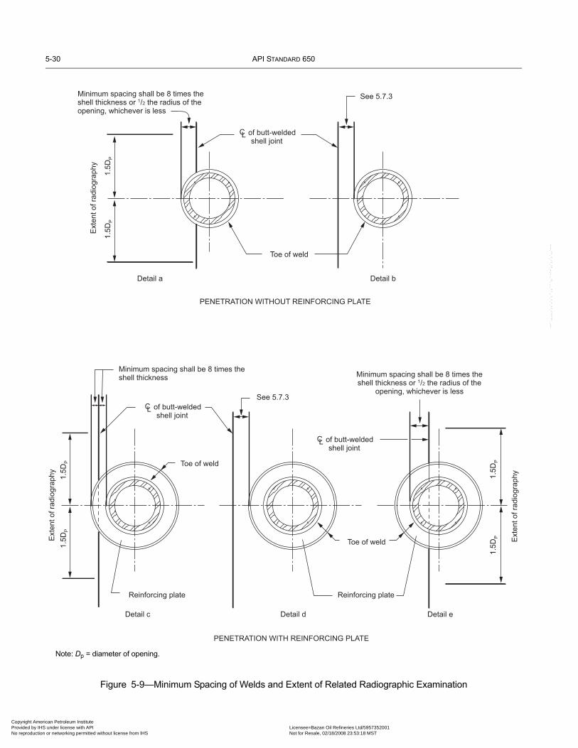
5-30 API STANDARD 650
Copyright AmProvided by No reproduc
--``,,,,,,`,,`,`,`,``,,````,,``-`-`,,`,,`,`,,`---
Figure 5-9—Minimum Spacing of Welds and Extent of Related Radiographic Examination
Toe of weld
Toe of weld
Reinforcing plateReinforcing plate
PENETRATION WITHOUT REINFORCING PLATE
PENETRATION WITH REINFORCING PLATE
Toe of weld
Minimum spacing shall be 8 times theshell thickness or 1/2 the radius of theopening, whichever is less
of butt-weldedshell joint
CL
See 5.7.3E
xten
t of r
adio
grap
hy
1.5D
P1.
5DP
Ext
ent o
f rad
iogr
aphy 1.5D
P1.
5DP
Minimum spacing shall be 8 times theshell thickness
of butt-weldedshell joint
CLSee 5.7.3
Minimum spacing shall be 8 times theshell thickness or 1/2 the radius of the
opening, whichever is less
Ext
ent o
f rad
iogr
aphy1.
5DP
1.5D
P
Detail a Detail b
Detail c Detail d Detail e
of butt-weldedshell joint
CL
Note: Dp = diameter of opening.
erican Petroleum Institute IHS under license with API Licensee=Bazan Oil Refineries Ltd/5957352001
Not for Resale, 02/18/2008 23:53:18 MSTtion or networking permitted without license from IHS

WELDED STEEL TANKS FOR OIL STORAGE 5-31
•
07
07
07
Copyright AmericaProvided by IHS uNo reproduction o
5.7.3.2 Where stress-relieving of the periphery weld has been performed prior to welding of the adjacent shell joint or wherea non-stress-relieved weld is on a shell plate less than or equal to 12.5 mm (1/2 in.) thick, the spacing may be reduced to150 mm (6 in.) from vertical joints or to the greater of 75 mm (3 in.) or 21/2 times the shell thickness from horizontal joints.The spacing between the welds around the periphery of a thickened insert plate or around a reinforcing plate shall be thegreater of 75 mm (3 in.) or 21/2 times the shell thickness.
5.7.3.3 The rules in 5.7.3.1 and 5.7.3.2 shall also apply to the bottom-to-shell joint unless, as an alternative, the insert plateor reinforcing plate extends to the bottom-to-shell joint and intersects it at approximately 90 degrees. A minimum distance of75 mm (3 in.) shall be maintained between the toe of a weld around a nonreinforced penetration (see 5.7.2.1) and the toe of theshell-to-bottom weld.
5.7.3.4 Nozzles and manholes should not be placed in shell weld seams and reinforcing pads for nozzles and manholesshould not overlap plate seams (i.e., Figure 5-9, Details a, c, and e should be avoided). If there is no other feasible option andthe Purchaser accepts the design, circular shell openings and reinforcing plates (if used) may be located in a horizontal or ver-tical butt-welded shell joint provided that the minimum spacing dimensions are met and a radiographic examination of thewelded shell joint is conducted. The welded shell joint shall be fully radiographed for a length equal to three times the diame-ter of the opening, but the weld seam being removed need not be radiographed. Radiographic examination shall be in accor-dance with 8.1.3 through 8.1.8.
5.7.4 Thermal Stress Relief
5.7.4.1 All flush-type cleanout fittings and flush-type shell connections shall be thermally stress-relieved as an assembly priorto installation in the tank shell or after installation into the tank shell if the entire tank is stress-relieved. The stress relief shall becarried out within a temperature range of 600°C – 650°C (1100°F – 1200°F) (see 5.7.4.3 for quenched and tempered materials)for 1 hour per 25 mm (1 in.) of shell thickness. The assembly shall include the bottom reinforcing plate (or annular plate) and theflange-to-neck weld.
5.7.4.2 When the shell material is Group I, II, III, or IIIA, all opening connections NPS 12 or larger in nominal diame-ter in a shell plate or thickened insert plate more than 25 mm (1 in.) thick shall be prefabricated into the shell plate orthickened insert plate, and the prefabricated assembly shall be thermally stress-relieved within a temperature range of600°C – 650°C (1100°F – 1200°F) for 1 hour per 25 mm (1 in.) of thickness prior to installation. The stress-relievingrequirements need not include the flange-to-neck welds or other nozzle-neck and manhole-neck attachments, providedthe following conditions are fulfilled:
a. The welds are outside the reinforcement (see 5.7.2.4).b. The throat dimension of a fillet weld in a slip-on flange does not exceed 16 mm (5/8 in.), or the butt joint of a welding-neck flange does not exceed 19 mm (3/4 in.). If the material is preheated to a minimum temperature of 90°C (200°F) duringwelding, the weld limits of 16 mm (5/8 in.) and 19 mm (3/4 in.) may be increased to 32 mm and 38 mm (11/4 in. and 11/2 in.),respectively.
5.7.4.3 When the shell material is Group IV, IVA, V, or VI, all opening connections requiring reinforcement in a shell plate orthickened insert plate more than 12.5 mm (1/2 in.) thick shall be prefabricated into the shell plate or thickened insert plate, and theprefabricated assembly shall be thermally stress relieved within a temperature range of 600°C – 650°C (1100°F – 1200°F) for 1hour per 25 mm (1 in.) of thickness prior to installation.
When connections are installed in quenched and tempered material, the maximum thermal stress-relieving temperatureshall not exceed the tempering temperature for the materials in the prefabricated stress-relieving assembly. The stress-relieving requirements do not apply to the weld to the bottom annular plate, but they do apply to flush-type cleanoutopenings when the bottom reinforcing plate is an annular-plate section. The stress-relieving requirements need notinclude the flange-to-neck welds or other nozzle-neck and manhole-neck attachments, provided the conditions of 5.7.4.2are fulfilled.5.7.4.4 Examination after stress relief shall be in accordance with 7.2.3.6 or 7.2.3.7.
--``,,,,,,`,,`,`,`,``,,````,,``-`-`,,`,,`,`,,`---
n Petroleum Institute nder license with API Licensee=Bazan Oil Refineries Ltd/5957352001
Not for Resale, 02/18/2008 23:53:18 MSTr networking permitted without license from IHS
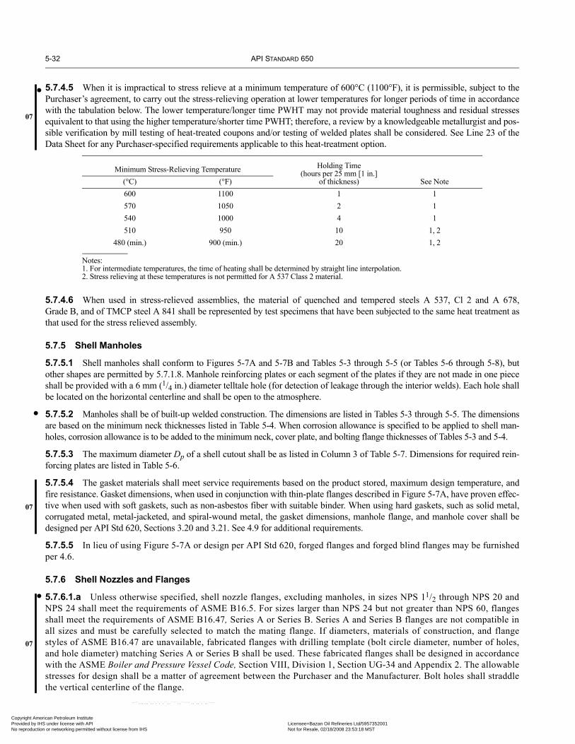
5-32 API STANDARD 650
•07
•
07
•
07
Copyright AmProvided by No reproduc
5.7.4.5 When it is impractical to stress relieve at a minimum temperature of 600°C (1100°F), it is permissible, subject to thePurchaser’s agreement, to carry out the stress-relieving operation at lower temperatures for longer periods of time in accordancewith the tabulation below. The lower temperature/longer time PWHT may not provide material toughness and residual stressesequivalent to that using the higher temperature/shorter time PWHT; therefore, a review by a knowledgeable metallurgist and pos-sible verification by mill testing of heat-treated coupons and/or testing of welded plates shall be considered. See Line 23 of theData Sheet for any Purchaser-specified requirements applicable to this heat-treatment option.
5.7.4.6 When used in stress-relieved assemblies, the material of quenched and tempered steels A 537, Cl 2 and A 678,Grade B, and of TMCP steel A 841 shall be represented by test specimens that have been subjected to the same heat treatment asthat used for the stress relieved assembly.
5.7.5 Shell Manholes
5.7.5.1 Shell manholes shall conform to Figures 5-7A and 5-7B and Tables 5-3 through 5-5 (or Tables 5-6 through 5-8), butother shapes are permitted by 5.7.1.8. Manhole reinforcing plates or each segment of the plates if they are not made in one pieceshall be provided with a 6 mm (1/4 in.) diameter telltale hole (for detection of leakage through the interior welds). Each hole shallbe located on the horizontal centerline and shall be open to the atmosphere.
5.7.5.2 Manholes shall be of built-up welded construction. The dimensions are listed in Tables 5-3 through 5-5. The dimensionsare based on the minimum neck thicknesses listed in Table 5-4. When corrosion allowance is specified to be applied to shell man-holes, corrosion allowance is to be added to the minimum neck, cover plate, and bolting flange thicknesses of Tables 5-3 and 5-4.
5.7.5.3 The maximum diameter Dp of a shell cutout shall be as listed in Column 3 of Table 5-7. Dimensions for required rein-forcing plates are listed in Table 5-6.
5.7.5.4 The gasket materials shall meet service requirements based on the product stored, maximum design temperature, andfire resistance. Gasket dimensions, when used in conjunction with thin-plate flanges described in Figure 5-7A, have proven effec-tive when used with soft gaskets, such as non-asbestos fiber with suitable binder. When using hard gaskets, such as solid metal,corrugated metal, metal-jacketed, and spiral-wound metal, the gasket dimensions, manhole flange, and manhole cover shall bedesigned per API Std 620, Sections 3.20 and 3.21. See 4.9 for additional requirements.
5.7.5.5 In lieu of using Figure 5-7A or design per API Std 620, forged flanges and forged blind flanges may be furnishedper 4.6.
5.7.6 Shell Nozzles and Flanges
5.7.6.1.a Unless otherwise specified, shell nozzle flanges, excluding manholes, in sizes NPS 11/2 through NPS 20 andNPS 24 shall meet the requirements of ASME B16.5. For sizes larger than NPS 24 but not greater than NPS 60, flangesshall meet the requirements of ASME B16.47, Series A or Series B. Series A and Series B flanges are not compatible inall sizes and must be carefully selected to match the mating flange. If diameters, materials of construction, and flangestyles of ASME B16.47 are unavailable, fabricated flanges with drilling template (bolt circle diameter, number of holes,and hole diameter) matching Series A or Series B shall be used. These fabricated flanges shall be designed in accordancewith the ASME Boiler and Pressure Vessel Code, Section VIII, Division 1, Section UG-34 and Appendix 2. The allowablestresses for design shall be a matter of agreement between the Purchaser and the Manufacturer. Bolt holes shall straddlethe vertical centerline of the flange.
Minimum Stress-Relieving Temperature Holding Time (hours per 25 mm [1 in.]
of thickness) See Note(°C) (°F)600 1100 1 1570 1050 2 1540 1000 4 1510 950 10 1, 2
480 (min.) 900 (min.) 20 1, 2
Notes:1. For intermediate temperatures, the time of heating shall be determined by straight line interpolation.2. Stress relieving at these temperatures is not permitted for A 537 Class 2 material.
erican Petroleum Institute IHS under license with API Licensee=Bazan Oil Refineries Ltd/5957352001
Not for Resale, 02/18/2008 23:53:18 MSTtion or networking permitted without license from IHS
--``,,,,,,`,,`,`,`,``,,````,,``-`-`,,`,,`,`,,`---

WELDED STEEL TANKS FOR OIL STORAGE 5-33
•
•
• 07
•
Copyright AmericaProvided by IHS uNo reproduction o
5.7.6.1.b Shell nozzles (and flanges, if specified by the Purchaser as an alternate to a. above) shall conform to Figures 5-7B, 5-8, and 5-10 and Tables 5-6 through 5-8, but other shapes are permitted by 5.7.1.8. An alternative connection design is permissiblefor the nozzle end that is not welded to the shell, if it provides equivalent strength, toughness, leak tightness, and utility and if thePurchaser agrees to its use in writing.
5.7.6.2 Unless shell nozzles are specified to be flush on the inside of the tank shell by the Purchaser, shell nozzles without inter-nal piping in a tank without a floating roof may be supplied flush or with an internal projection at the option of the Manufacturer.In floating roof tanks, shell nozzles without internal piping within operating range of the floating roof shall be supplied flush onthe inside of the tank shell unless agreed otherwise between the Manufacturer and the Purchaser.
5.7.6.3 The details and dimensions specified in this Standard are for nozzles installed with their axes perpendicular to the shellplate. A nozzle may be installed at an angle other than 90 degrees to the shell plate in a horizontal plane, provided the width of thereinforcing plate (W or Do in Figure 5-8 and Table 5-6) is increased by the amount that the horizontal chord of the opening cut inthe shell plate (Dp in Figure 5-8 and Table 5-7) increases as the opening is changed from circular to elliptical for the angularinstallation. In addition, nozzles not larger than NPS 3—for the insertion of thermometer wells, for sampling connections, or forother purposes not involving the attachment of extended piping—may be installed at an angle of 15 degrees or less off perpendic-ular in a vertical plane without modification of the nozzle reinforcing plate.
5.7.6.4 The minimum as-built thickness of nozzle necks to be used shall be equal to the required thickness as identified by theterm tn in Table 5-6, Column 3.
5.7.7 Flush-Type Cleanout Fittings
5.7.7.1 Flush-type cleanout fittings shall conform to the requirements of 5.7.7.2 through 5.7.7.12 and to the details and dimensionsshown in Figures 5-12 and 5-13 and Tables 5-9 through 5-11. When a size intermediate to the sizes given in Tables 5-9 through 5-11is specified by the Purchaser, the construction details and reinforcements shall conform to the next larger opening listed in the tables.The size of the opening or tank connection shall not be larger than the maximum size given in the appropriate table.
5.7.7.2 The opening shall be rectangular, but the upper corners of the opening shall have a radius equal to one-half the greatestheight of the clear opening. When the shell material is Group I, II, III, or IIIA, the width or height of the clear opening shall notexceed 1200 mm (48 in.); when the shell material is Group IV, IVA, V, or VI, the height shall not exceed 900 mm (36 in.).
5.7.7.3 The reinforced opening shall be completely preassembled into a shell plate, and the completed unit, including the shellplate at the cleanout fitting, shall be thermally stress-relieved as described in 5.7.4 (regardless of the thickness or strength of thematerial).
Figure 5-10—Shell Nozzle Flanges (See Table 5-8)
PLATE-RING SLIP-ONWELDING FLANGE
HUB SLIP-ON WELDINGFLANGE
WELDING-NECK FLANGE
AC
DB
AC
DB
AC
D
1.5 mm(1/16") 1.5 mm
(1/16")1.5 mm(1/16")
tn + 6 mm (1/4") max tn + 6 mm (1/4") max
tn min
Q QE1
B1
tnmin
Q
E75°
1.4tn
Note: The tn designated for weld thickness is the nominal pipe wall thickness (see Tables 5-6 and 5-7).
--``,,,,,,`,,`,`,`,``,,````,,``-`-`,,`,,`,`,,`---
n Petroleum Institute nder license with API Licensee=Bazan Oil Refineries Ltd/5957352001
Not for Resale, 02/18/2008 23:53:18 MSTr networking permitted without license from IHS

5-34 API STANDARD 650
Copyright AmProvided by No reproduc
--``,,,,,,`,,`,`,`,``,,````,,``-`-`,,`,,`,`,,`---
5.7.7.4 The cross-sectional area of the reinforcement over the top of the opening shall be calculated as follows:
whereAcs = cross-sectional area of the reinforcement over the top of the opening, in mm2 (in.2),K1 = area coefficient from Figure 5-11,
h = vertical height of clear opening, in mm (in.),t = calculated thickness of the lowest shell course, in mm (in.), required by the formulas of 5.6.3, 5.6.4, or A.4.1 but
exclusive of any corrosion allowance.
5.7.7.5 The thickness of the shell plate in the flush-type cleanout fitting assembly shall be at least as thick as the adjacent shellplate in the lowest shell course. The thickness of the shell reinforcing plate and the neck plate shall be the same as the thickness ofthe shell plate in the cleanout-opening assembly.The reinforcement in the plane of the shell shall be provided within a height L above the bottom of the opening. L shall not exceed1.5h except that, in the case of small openings, L – h shall not be less than 150 mm (6 in.). Where this exception results in an Lthat is greater than 1.5h, only the portion of the reinforcement that is within the height of 1.5h shall be considered effective. Thereinforcement required may be provided by any one or any combination of the following:
a. The shell reinforcing plate.b. Any thickness of the shell plate in the flush-type cleanout fitting assembly that is greater than the thickness of the adjacentplates in the lowest shell course.c. The portion of the neck plate having a length equal to the thickness of the reinforcing plate.
Figure 5-11—Area Coefficient for Determining Minimum Reinforcement of Flush-Type Cleanout Fittings
0
0.25
0.50
0.75
1.00
1.25
1.0 1.1 1.2 1.3 1.4
Minimum K1
Maximum K1
(H + 29)D + 770385h
17,850t2.6D (H – 1)
K1 coefficient
0.5
(H + 8.8)D + 71.51.408h
123t4.9D (H – 0.3)
0.5
Vertical axis in SI units:
Vertical axis in US Customary units:
AcsK1ht
2-----------≥
erican Petroleum Institute IHS under license with API Licensee=Bazan Oil Refineries Ltd/5957352001
Not for Resale, 02/18/2008 23:53:18 MSTtion or networking permitted without license from IHS

WELDED STEEL TANKS FOR OIL STORAGE 5-35
Copyright AmericaProvided by IHS uNo reproduction o
Figure 5-12—Flush-Type Cleanout Fittings (See Tables 5-9, 5-10, and 5-11)
Shell plate at cleanout fitting = t d
See Detail b
Equal spaces
Nearest horizontal weld
125 mm(5")
One telltale 6 mm (1/4")hole in reinforcingplate at aboutmid-height
r2
Reinforcing plate = t d
Shell plateof lowestshellcourse = t
(See Note 1)
6 mm(1/4") 6 mm
(1/4")
6 mm(1/4")
6 mm (1/4")
6 mm(1/4")
6 mm(1/4")
6 mm(1/4")
5 mm(3/16")
5 mm(3/16")
5 mm (3/16")
gB
B
300 mm(12") min
150 mm(6") min
W /2 arc dimensions
Flange bolt-holediameter = boltdiameter (see Table3-9) + 3 mm (1/8")
b /2
f 2
r1 L
A
A
f3e
eEqual spacesf 3 /2 – 6 mm (1/4")
See Detail a
t d
See Detail bfor top and sides
t c
t b
h
Bottomplate
e
SECTION A-A
Grind radius on cornerwhen weld is less than t d
t d[40 mm (11/2") max]
t d
t d
t c
t d[20 mm (3/4") max]
t d
Neck bevel shall beapproximately 10 degrees
f3
(SeeNote 1)
Cover plate
Versine
Detail aSECTION B-B
t d
t d
t b
(See Note 1)
Full-filletweld
t d + t d + 250 mm (10")(see Note 2)
32 mm(11/4") min
DD 90 degrees ± 30 degrees
32 mm (11/4") min125 mm (5") min
SECTION C-C
SECTION D-D
32 mm(11/4")min
75 mm (3") radius
10 mm (3/8") thick175 mm (5")
40 mm (11/2")
40 mm (11/2")
40 mm(11/2")
50 mm(2")
or
Full-penetrationweld
(See Note 3)
75 mm(3")
CC
Roundand grind
Detail b
Lifting Lug
Notch as required to provide flush joint under shell ring (see Section D–D)
375 mm(15") min
(See Note 5)
(See Note 5)
(See Note 5)
Notes:1. Thickness of thinner plate joined (13 mm [1/2 in.] maximum).2. When an annular plate is provided, the reinforcing plate shall be
regarded as a segment of the annular plate and shall be the samewidth as the annular plate.
3. When the difference between the thickness of the annular ring andthat of the bottom reinforcing plate is less than 6 mm (1/4 in.), theradial joint between the annular ring and the bottom reinforcing plate
may be butt-welded with a weld joint suitable for completepenetration and fusion.
4. Gasket material shall be specified by the Purchaser. The gasket mate-rial shall meet service requirements based on product stored, designmetal temperature, maximum design temperature and fire resistance.
5. The thickness (td) of the shell plate at the cleanout opening, thereinforcing plate, and the neck plate, shall be equal to or greaterthan the thickness (t) of the shell plate of the lowest shell course.
•
--``,,,,,,`,,`,`,`,``,,````,,``-`-`,,`,,`,`,,`---
n Petroleum Institute nder license with API Licensee=Bazan Oil Refineries Ltd/5957352001
Not for Resale, 02/18/2008 23:53:18 MSTr networking permitted without license from IHS
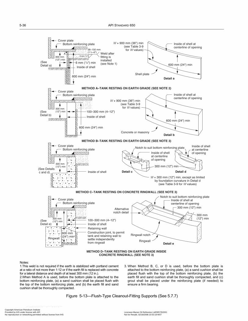
5-36 API STANDARD 650
Copyright AmProvided by No reproduc
Figure 5-13—Flush-Type Cleanout-Fitting Supports (See 5.7.7)
METHOD A–TANK RESTING ON EARTH GRADE (SEE NOTE 2)
METHOD B–TANK RESTING ON EARTH GRADE (SEE NOTE 3)
METHOD C–TANK RESTING ON CONCRETE RINGWALL (SEE NOTE 3)
METHOD D–TANK RESTING ON EARTH GRADE INSIDECONCRETE RINGWALL (SEE NOTE 3)
Cover plateBottom reinforcing plate
300 mm(12") min
(SeeDetail a)
600 mm (24") min
Inside of shell
6 mm (1/4") min
38–150 mm (11/2–6") Weld after
fitting isinstalled(see Note 1)
Cover plateBottom reinforcing plate
(SeeDetail b) Inside of shell
100–300 mm (4–12")
Cover plateBottom reinforcing plate
(See Detailsc and d) Inside of shell
Cover plateBottom reinforcing plate
(SeeDetail e) Inside of shell
100–300 mm (4–12")
Retaining wallConstruction joint, to permittank and retaining wall tosettle independentlyfrom ringwall
W + 900 mm (36") min(see Table 3-9
for W values)
600 mm (24") min
300 mm(12") min
300 mm(12") min
300 mm(12") min
600 mm (24") min
W + 900 mm (36") min(see Table 3-9
for W values)
600 mm (24") min
Shell plate
Concrete or masonry
Inside of shell atcenterline of opening
Inside of shell atcenterline of opening
Inside of shellat centerlineof opening
Notch to suit bottom reinforcing plate
Inside of shellat centerlineof opening
300 mm (12") min
W + 300 mm (12") min, except as limitedby foundation curvature in Detail d
(see Table 3-9 for W values)
Notch to suit bottom reinforcing plateInside of shell atcenterline of opening
300 mm (12") min
300 mm(12") min
Ringwall
Ringwall notch
Alternativenotch detail
Detail a
Detail b
Detail c Detail d
Detail e
Ringwall
600 mm(24") min
6 mm (1/4")
Notes:1.This weld is not required if the earth is stabilized with portland cementat a ratio of not more than 1:12 or if the earth fill is replaced with concretefor a lateral distance and depth of at least 300 mm (12 in.).2.When Method A is used, before the bottom plate is attached to thebottom reinforcing plate, (a) a sand cushion shall be placed flush withthe top of the bottom reinforcing plate, and (b) the earth fill and sandcushion shall be thoroughly compacted.
3. When Method B, C, or D is used, before the bottom plate isattached to the bottom reinforcing plate, (a) a sand cushion shall beplaced flush with the top of the bottom reinforcing plate, (b) theearth fill and sand cushion shall be thoroughly compacted, and (c)grout shall be placed under the reinforcing plate (if needed) toensure a firm bearing.
erican Petroleum Institute IHS under license with API Licensee=Bazan Oil Refineries Ltd/5957352001
Not for Resale, 02/18/2008 23:53:18 MSTtion or networking permitted without license from IHS
--``,,,,,,`,,`,`,`,``,,````,,``-`-`,,`,,`,`,,`---

WELDED STEEL TANKS FOR OIL STORAGE 5-37
Copyright AmericaProvided by IHS uNo reproduction o
--``,,,,,,`,,`,`,`,``,,````,,``-`-`,,`,,`,`,,`---
5.7.7.6 The minimum width of the tank-bottom reinforcing plate at the centerline of the opening shall be 250 mm (10 in.) plusthe combined thickness of the shell plate in the cleanout-opening assembly and the shell reinforcing plate. The minimum thickness of the bottom reinforcing plate shall be determined by the following equation:
In SI units:
where
tb = minimum thickness of the bottom reinforcing plate, in mm,
h = vertical height of clear opening, in mm,
b = horizontal width of clear opening, in mm,
H = maximum design liquid level (see 5.6.3.2), in m,
G = specific gravity, not less than 1.0.
In US Customary units:
where
tb = minimum thickness of the bottom reinforcing plate, (in.),
h = vertical height of clear opening, (in.),
b = horizontal width of clear opening, (in.),
H = maximum design liquid level (see 5.6.3.2), (ft),
G = specific gravity, not less than 1.0.
5.7.7.7 The dimensions of the cover plate, bolting flange, bolting, and bottom-reinforcing plate shall conform to Tables 5-9 and5-10.
5.7.7.8 All materials in the flush-type cleanout fitting assembly shall conform to the requirements in Section 4. The shell platecontaining the cleanout assembly, the shell reinforcing plate, the neck plate, and the bottom reinforcing plate shall meet the impacttest requirements of 4.2.9 and Figure 4-1 for the respective thickness involved at the design metal temperature for the tank. Thenotch toughness of the bolting flange and the cover plate shall be based on the governing thickness as defined in 4.5.5.3 usingTable 4-3(a), Table 4-3(b), and Figure 4-1. Additionally, the yield strength and the tensile strength of the shell plate at the flush-type cleanout fitting, the shell reinforcing plate, and the neck plate shall be equal to, or greater than, the yield strength and the ten-sile strength of the adjacent lowest shell course plate material.
5.7.7.9 The dimensions and details of the cleanout-opening assemblies covered by this section are based on internal hydrostaticloading with no external-piping loading.
5.7.7.10 When a flush-type cleanout fitting is installed on a tank that is resting on an earth grade without concrete or masonrywalls under the tank shell, provision shall be made to support the fitting and retain the grade by either of the following methods:
a. Install a vertical steel bulkhead plate under the tank, along the contour of the tank shell, symmetrical with the opening, asshown in Figure 5-13, Method A.b. Install a concrete or masonry retaining wall under the tank with the wall’s outer face conforming to the contour of the tankshell as shown in Figure 5-13, Method B.
5.7.7.11 When a flush-type cleanout fitting is installed on a tank that is resting on a ringwall, a notch with the dimensionsshown in Figure 5-13, Method C, shall be provided to accommodate the cleanout fitting.
tbh2
360,000------------------- b
170--------- HG+=
tbh2
14,000---------------- b
310--------- HG+=
n Petroleum Institute nder license with API Licensee=Bazan Oil Refineries Ltd/5957352001
Not for Resale, 02/18/2008 23:53:18 MSTr networking permitted without license from IHS

5-38 API STANDARD 650
•
Copyright AmProvided by No reproduc
--``,,,,,,`,,`,`,`,``,,````,,``-`-`,,`,,`,`,,`---
5.7.7.12 When a flush-type cleanout fitting is installed on a tank that is resting on an earth grade inside a foundation retainingwall, a notch shall be provided in the retaining wall to accommodate the fitting, and a supplementary inside retaining wall shall beprovided to support the fitting and retain the grade. The dimensions shall be as shown in Figure 5-13, Method D.
5.7.8 Flush-Type Shell Connections
5.7.8.1 Tanks may have flush-type connections at the lower edge of the shell. Each connection may be made flush with the flatbottom under the following conditions (see Figure 5-14):
a. The shell uplift from the internal design and test pressures (see Appendix F) and wind and earthquake loads (see Appendix E)shall be counteracted so that no uplift will occur at the cylindrical-shell/flat-bottom junction.b. The vertical or meridional membrane stress in the cylindrical shell at the top of the opening for the flush-type connection shallnot exceed one-tenth of the circumferential design stress in the lowest shell course containing the opening.c. The maximum width, b, of the flush-type connection opening in the cylindrical shell shall not exceed 900 mm (36 in.).d. The maximum height, h, of the opening in the cylindrical shell shall not exceed 300 mm (12 in.).e. The thickness, ta, of the bottom-transition plate in the assembly shall be 12.5 mm (1/2 in.) minimum or, when specified, thesame as the thickness of the tank annular plate.
5.7.8.2 The details of the connection shall conform to those shown in Figure 5-14, and the dimensions of the connection shallconform to Table 5-12 and to the requirements of 5.7.8.3 through 5.7.8.11.
5.7.8.3 The reinforced connection shall be completely preassembled into a shell plate. The completed assembly, including theshell plate containing the connection, shall be thermally stress-relieved at a temperature of 600°C – 650°C (1100°F – 1200°F) for1 hour per 25 mm (1 in.) of shell-plate thickness, td (see 5.7.4.1 and 5.7.4.2).
5.7.8.4 The reinforcement for a flush-type shell connection shall meet the following requirements:
a. The cross-sectional area of the reinforcement over the top of the connection shall not be less than K1ht/2 (see 5.7.7.4).b. The thickness of the shell plate, td, for the flush-connection assembly shall be at least as thick as the adjacent shell plate, t, inthe lowest shell course.c. The thickness of the shell reinforcing plate shall be the same as the thickness of the shell plate in the flush-connectionassembly.d. The reinforcement in the plane of the shell shall be provided within a height L above the bottom of the opening. L shall notexceed 1.5h except that, in the case of small openings, L – h shall not be less than 150 mm (6 in.). Where this exception results inan L that is greater than 1.5h, only the portion of the reinforcement that is within the height of 1.5h shall be considered effective.e. The required reinforcement may be provided by any one or any combination of the following: (1) the shell reinforcing plate,(2) any thickness of the shell plate in the assembly that is greater than the thickness of the adjacent plates in the lowest shellcourse, and (3) the portion of the neck plate having a length equal to the thickness of the reinforcing plate.f. The width of the tank-bottom reinforcing plate at the centerline of the opening shall be 250 mm (10 in.) plus the combinedthickness of the shell plate in the flush-connection assembly and the shell reinforcing plate. The thickness of the bottom reinforc-ing plate shall be calculated by the following equation (see 5.7.7.6):
In SI units:
where
tb = minimum thickness of the bottom reinforcing plate, in mm,
h = vertical height of clear opening, in mm,b = horizontal width of clear opening, in mm,H = maximum design liquid level (see 5.6.3.2), in m,G = specific gravity, not less than 1.0.
tbh2
360,000------------------- b
170--------- HG+=
erican Petroleum Institute IHS under license with API Licensee=Bazan Oil Refineries Ltd/5957352001
Not for Resale, 02/18/2008 23:53:18 MSTtion or networking permitted without license from IHS

WELDED STEEL TANKS FOR OIL STORAGE 5-39
Copyright AmericaProvided by IHS uNo reproduction o
Figure 5-14—Flush-Type Shell Connection
tn = 16 mm (5/8") min
One 6 mm (1/4") telltalehole in reinforcing plateat about mid-height
SECTION B-B
SECTION A-A
B
h
50 mm (2") min
150 mm(6") min
W/2 arc dimensions
150 mm (6") min
L
375 mm (15") min
C
C
Shell plate inflush connection = td
Reinforcing plate = td
B
75 mm(3")
Bottom reinforcing plate
Shell plate oflowest shellcourse = t
See Section C-C(Figure 5-11 —continued)
Centerline of connection
tb
td
td
32 mm (11/4") min
Bottom reinforcing plate
A
A
Butt-weldNozzle transition to
circular flange
Butt-weld
75 mm(3") radius
125 mm (5") min
Full-fillet weld
All joints approximately90 degrees
Bottom plate
Bottom transition plate for minimumarc dimension of W + 1500 mm (60")
2td + 250 mm (10")
(See note)
Centerlineof connection
600 mm(24") min
32 mm(11/4") min
Notch as required to provideflush joint
Full-penetrationweld
5 mm(3/16")
6 mm(1/4")
r2
r1
b/2
300 mm(12") min
Note: Thickness of thinner plate joined 13 mm (1/2 in.) maximum.
--``,,,,,,`,,`,`,`,``,,````,,``-`-`,,`,,`,`,,`---
n Petroleum Institute nder license with API Licensee=Bazan Oil Refineries Ltd/5957352001
Not for Resale, 02/18/2008 23:53:18 MSTr networking permitted without license from IHS

5-40 API STANDARD 650
Copyright AmProvided by No reproduc
Figure 5-14—Flush-Type Shell Connection (continued)
(See note)
td(38 mm [11/2"] max)
Round cornerwhen td > 38 mm (11/2")
125 mm(5")
td
tn
td
b/2 (min)
tn = 16 mm (5/8") min
Nozzle transition
Flanges per Table 5-10
See (1)
Typical Detail for Connections with b = h
tbta = 13 mm (1/2") min
2td + 250 mm (10")
h
Centerline ofnozzle flange andshell opening
Bottom plate
Bottomreinforcing
plate tb
Bottomtransitionplate ta
Full-penetration weld
1
4
Alternativebutt-weld detail
Bottomtransitionplate ta
6 mm(1/4") min
32 mm(11/4") min
Bottomreinforcing
plate tb
Full-penetrationweld
Flanges per Table 5-8
tn
tb
2td + 250 mm (10")h
Centerlineof nozzle
flange
tn = 16 mm (5/8") min
ta
Bottom plate
Round corner
td[38 mm (11/2") max]
b/2125 mm
(5")
td
td
Roundcorner
when td =38 mm (11/2")
a
< 30º
Nozzle transition(see 5.7.8.4, Item g)
Nozzle neck(see 5.7.8.4,
Item g)
Back chipand weld
(See note)
tn
14
14
14
Round corner
Full-penetrationweld
tn
SECTION C-C
Typical Detail for Connections with b > h
Notes: Thickness of thinner plate joined 13 mm (1/2 in.) maximum.(1) Flange weld sizes shall be the smaller of available hub material or tn.
erican Petroleum Institute IHS under license with API Licensee=Bazan Oil Refineries Ltd/5957352001
Not for Resale, 02/18/2008 23:53:18 MSTtion or networking permitted without license from IHS
--``,,,,,,`,,`,`,`,``,,````,,``-`-`,,`,,`,`,,`---
WELDED STEEL TANKS FOR OIL STORAGE 5-41
Copyright AmericaProvided by IHS uNo reproduction o
In US Customary units:
where
tb = minimum thickness of the bottom reinforcing plate, (in.),h = vertical height of clear opening, (in.),b = horizontal width of clear opening, (in.),H = maximum design liquid level (see 5.6.3.2), (ft),G = specific gravity, not less than 1.0.
The minimum value of tb shall be:
16 mm (5/8 in.) for HG ≤ 14.4 m (48 ft)
17 mm (11/16 in.) for 14.4 m (48 ft) < HG ≤ 16.8 m (56 ft)
19 mm (3/4 in.) for 16.8 m (56 ft) < HG ≤ 19.2 m (64 ft)
g. The minimum thickness of the nozzle neck and transition piece, tn, shall be 16 mm (5/8 in.). External loads applied to the con-nection may require tn to be greater than 16 mm (5/8 in.).
5.7.8.5 All materials in the flush-type shell connection assembly shall conform to the requirements in Section 4. The materialof the shell plate in the connection assembly, the shell reinforcing plate, the nozzle neck attached to the shell, the transition piece,and the bottom reinforcing plate shall conform to 4.2.9 and Figure 4-1 for the respective thickness involved at the design metaltemperature for the tank. The notch toughness of the bolting flange and the nozzle neck attached to the bolting flange shall bebased on the governing thickness as defined in 4.5.5.3 and used in Figure 4-1. Additionally, the yield strength and the tensilestrength of the shell plate at the flush-type shell connection and the shell reinforcing plate shall be equal to, or greater than, theyield strength and the tensile strength of the adjacent lowest shell course plate material.
5.7.8.6 The nozzle transition between the flush connection in the shell and the circular pipe flange shall be designed in a man-ner consistent with the requirements of this Standard. Where this Standard does not cover all details of design and construction,the Manufacturer shall provide details of design and construction that will be as safe as the details provided by this Standard.
5.7.8.7 Where anchoring devices are required by Appendices E and F to resist shell uplift, the devices shall be spaced so thatthey will be located immediately adjacent to each side of the reinforcing plates around the opening.
5.7.8.8 Adequate provision shall be made for free movement of connected piping to minimize thrusts and moments applied tothe shell connection. Allowance shall be made for the rotation of the shell connection caused by the restraint of the tank bottom-to-shell expansion from stress and temperature as well as for the thermal and elastic movement of the piping. Rotation of the shellconnection is shown in Figure 5-15.
5.7.8.9 The foundation in the area of a flush-type connection shall be prepared to support the bottom reinforcing plate of theconnection. The foundation for a tank resting on a concrete ringwall shall provide uniform support for both the bottom reinforcingplate and the remaining bottom plate under the tank shell. Different methods of supporting the bottom reinforcing plate under aflush-type connection are shown in Figure 5-13.
5.7.8.10 Flush-type connections may be installed using a common reinforcing pad; however, when this construction isemployed, the minimum distance between nozzle centerlines shall not be less than 1.5[b1 + b2 + 65 mm (21/2 in.)], where b1 andb2 are the widths of adjacent openings, or 600 mm (24 in.), whichever is greater. The width of each opening, b, shall be obtainedfrom Table 5-12 for the respective nominal flange size. Adjacent shell flush-type connections that do not share a common rein-forcing plate shall have at least a 900 mm (36 in.) clearance between the ends of their reinforcing plates.
5.7.8.11 All longitudinal butt-welds in the nozzle neck and transition piece, if any, and the first circumferential butt-weld in theneck closest to the shell, excluding neck-to-flange weld, shall receive 100% radiographic examination (see 8.1). The nozzle-to-tank-shell and reinforcing plate welds and the shell-to-bottom reinforcing plate welds shall be examined for their complete lengthby magnetic particle examination (see 8.2). The magnetic particle examination shall be performed on the root pass, on every
tbh2
14,000---------------- b
310--------- HG+=
--``,,,,,,`,,`,`,`,``,,````,,``-`-`,,`,,`,`,,`---
n Petroleum Institute nder license with API Licensee=Bazan Oil Refineries Ltd/5957352001
Not for Resale, 02/18/2008 23:53:18 MSTr networking permitted without license from IHS

5-42 API STANDARD 650
Copyright AmProvided by No reproduc
--``,,,,,,`,,`,`,`,``,,````,,``-`-`,,`,,`,`,,`---
12.5 mm (1/2 in.) of deposited weld metal while the welds are made, and on the completed welds. The completed welds shall alsobe visually examined. The examination of the completed welds shall be performed after stress-relieving but before hydrostatictesting (see 8.2 and 8.5 for the appropriate inspection and repair criteria).
5.8 SHELL ATTACHMENTS AND TANK APPURTENANCES
5.8.1 Shell Attachments
5.8.1.1 Shell attachments shall be made, inspected, and removed in conformance with Section 7.
a. Permanent attachments are items welded to the shell that will remain while the tank is in its intended service. These includeitems such as wind girders, stairs, gauging systems, davits, walkways, tank anchors, supports for internal items such as heatingcoils and other piping supports, ladders, floating roof supports welded to the shell, exterior piping supports, grounding clips, insu-
Figure 5-15—Rotation of Shell Connection
Position of shell afterelastic movement
Initial shell radius = R
Shell radius = R + ΔR
Height of bendingin shell varies with
tank radius and thickness
Transition plate
BottomReinforcing plate
Inside diameter of shell
75 mm (3") min
(See Details a and b)
Initial centerlineof connection
Angle ofrotation
Centerline ofconnection after
elastic movementof shell
Inside of shell atcenterline of opening
75 mm(3") min
75 mm(3") min
Inside of shell atcenterline of opening
Notch to suit bottom reinforcing plate
W + 300 mm (12") min,except as limited by
curvature of foundation(see Detail b)
Detail a Detail b
DETAILS OF NOTCH IN RINGWALL
θ
erican Petroleum Institute IHS under license with API Licensee=Bazan Oil Refineries Ltd/5957352001
Not for Resale, 02/18/2008 23:53:18 MSTtion or networking permitted without license from IHS
WELDED STEEL TANKS FOR OIL STORAGE 5-43
•
07
Copyright AmericaProvided by IHS uNo reproduction o
lation rings, and electrical conduit and fixtures. Items installed above the maximum liquid level of the tank are not permanentattachments. b. Temporary attachments are items welded to the shell that will be removed prior to the tank being commissioned into itsintended service. These include items such as alignment clips, fitting equipment, stabilizers, and lifting lugs.
5.8.1.2 When attachments are made to shell courses of material in Group IV, IVA, V, or VI, the movement of the shell (particu-larly the movement of the bottom course) under hydrostatic loading shall be considered, and the attachments shall meet the fol-lowing requirements:
a. Permanent attachments may be welded directly to the shell with fillet welds having a maximum leg dimension of 13 mm (1/2 in.).The edge of any permanent attachment welds shall be at least 75 mm (3 in.) from the horizontal joints of the shell and at least150 mm (6 in.) from the vertical joints, insert-plate joints, or reinforcing-plate fillet welds. Permanent attachment welds may crossshell horizontal or vertical butt welds providing the welds are continuous within these limits and the angle of incidence between thetwo welds is greater than or equal to 45 degrees. Additionally, any splice weld in the permanent attachment shall be located a mini-mum of 150 mm (6 in.) from any shell weld unless the splice weld is kept from intersecting the shell weld by acceptablemodifications to the attachment.b. The welding and inspection of permanent attachments to these shell courses shall conform to 7.2.3.5.c. Temporary attachments to shell courses shall preferably be made prior to welding of the shell joints. Weld spacing for tempo-rary attachments made after welding of the shell joints shall be the same as that required for permanent attachments. Temporaryattachments to shell courses shall be removed, and any resulting damage shall be repaired and ground to a smooth profile.
5.8.2 Bottom Connections
Connections to the tank bottom are permitted subject to agreement between the Purchaser and the Manufacturer with respect todetails that provide strength, tightness, and utility equal to the details of shell connections specified in this Standard.
5.8.3 Cover Plates
5.8.3.1 Unreinforced openings less than or equal to NPS 2 pipe size are permissible in flat cover plates without increasing thecover plate thickness if the edges of the openings are not closer to the center of the cover plate than one-fourth the height or diam-eter of the opening. Requirements for openings NPS 2 pipe size and smaller that do not satisfy the location requirement and forlarger reinforced openings are given in 5.8.3.2 through 5.8.3.4.
5.8.3.2 Reinforced openings in the cover plates of shell manholes shall be limited to one-half the diameter of the manholeopening but shall not exceed NPS 12 pipe size. The reinforcement added to an opening may be a reinforcing plate or an increasedthickness of the cover plate, but in either case, the reinforcement shall provide an added reinforcing area no less than the cutoutarea of the opening in the cover plate.A cover plate with a nozzle attachment for product-mixing equipment shall have a thickness at least 1.4 times greater than thethickness required by Table 5-3. The added thickness (or pad plate) for replacement of the opening cutout in the cover plate shallbe based on Table 5-3. The 40% increase in thickness within a radius of one diameter of the opening may be included as part ofthe area of replacement required. The mixer-nozzle attachment to the cover plate shall be a full-penetration weld. The manholebolting-flange thickness shall not be less than 1.4 times the thickness required by Table 5-3. The manhole nozzle neck shall bedesigned to support the mixer forces with a minimum thickness not less than the requirements of Table 5-4 without comparison tothe increased bolting-flange thickness noted in this section.
5.8.3.3 When cover plates (or blind flanges) are required for shell nozzles, the minimum thickness shall be that given forflanges in Table 5-8. Reinforced openings in the cover plates (or blind flanges) of shell nozzles shall be limited to one-half thediameter of the nozzle. The reinforcement added to an opening may be an added pad plate or an increased thickness of the coverplate, but in either case, the reinforcement shall provide an added reinforcing area no less than 50% of the cutout area of the open-ing in the cover plate. Mixer nozzles may be attached to cover plates.
5.8.3.4 Openings in the cover plates of flush-type cleanout fittings shall be limited to NPS 2 pipe size in accordance with5.8.3.1.
5.8.3.5 Shell manhole covers shall have two handles. Those covers weighing more than 34 kg (75 lb) shall be equipped witheither a hinge or davit to facilitate the handling of the manhole cover plate. The davit support arm shall not be welded directly tothe shell without a reinforcing plate.
--``,,,,,,`,,`,`,`,``,,````,,``-`-`,,`,,`,`,,`---
n Petroleum Institute nder license with API Licensee=Bazan Oil Refineries Ltd/5957352001
Not for Resale, 02/18/2008 23:53:18 MSTr networking permitted without license from IHS

5-44 API STANDARD 650
•
07
•
Copyright AmProvided by No reproduc
5.8.4 Roof Manholes
Roof manholes shall conform to Figure 5-16 and Table 5-13. If work is expected to be carried on through the manhole openingwhile the tank is in use, the roof structure around the manhole shall be reinforced.
5.8.5 Roof Venting
5.8.5.1 Tanks designed in accordance with this Standard and having a fixed roof shall be vented for both normal conditions(resulting from operational requirements, including maximum filling and emptying rates, and atmospheric temperature changes)and emergency conditions (resulting from exposure to an external fire). Tanks with both a fixed roof and a floating roof satisfythese requirements when they comply with the circulation venting requirements of Appendix H. All other tanks designed inaccordance with this Standard and having a fixed roof shall meet the venting requirements of 5.8.5.2 and 5.8.5.3.
5.8.5.2 Normal venting shall be adequate to prevent internal or external pressure from exceeding the corresponding tank designpressures and shall meet the requirements specified in API Std 2000 for normal venting.
5.8.5.3 Emergency venting requirements are satisfied if the tank is equipped with a weak roof-to-shell attachment (frangible joint)in accordance with 5.10.2.6, or if the tank is equipped with pressure relief devices meeting the requirements specified in API Std2000 for emergency venting. When pressure relief devices are used to satisfy the emergency venting requirements, they shall achievethe flow rates specified in API Std 2000 without exceeding the following limits on internal pressure:
a. For unanchored tanks, the pressure relief devices shall be adequate to prevent internal pressure from exceeding the tank designpressure as determined in F.4.1 (subject to the limitations in F.4.2 and F.4.3, as applicable). In calculating limitations per F.4.2, useM = 0. b. For anchored tanks, except those designed to F.1.3, the pressure relief devices shall be adequate to prevent internal pressurefrom exceeding the tank design pressure as determined in F.4.1 (subject to the limitations in F.4.3, as applicable).c. For tanks designed to F.1.3 (anchored tanks), the pressure relief devices shall be adequate to prevent internal pressure fromexceeding the design pressure specified by the Purchaser.
5.8.5.4 The filling and emptying rates are specified on the Data Sheet, Line 7. See the Data Sheet, Table 3 for venting devices,which shall be specified by the Purchaser and verified by the Manufacturer.
5.8.5.5 Corrosion-resistant coarse-mesh bird screens (13 mm [1/2 in.] nominal openings) shall protect all free vents.
5.8.5.6 Flanged roof nozzles shall conform to Figure 5-19 and Table 5-14. Slip-on flanges and weld neck flanges shall conformto the requirements of ASME B16.5 for Class 150 plate-ring flanges shall conform to all of the dimensional requirements for slip-on welding flanges with the exception that it is acceptable to omit the extended hub on the back of the slip-on or weld neckflanges. Raised face flanges shall be provided for nozzles with attached piping. Flat face flanges shall be provided for roof nozzlesused for the mounting of tank accessories.
5.8.5.7 Threaded roof nozzles shall conform to Figure 5-20 and Table 5-15.
5.8.6 Rectangular Roof Openings
5.8.6.1 Rectangular roof openings in supported roofs shall conform to Figure 5-17 or 5-18 and/or this section. If work isexpected to be carried on through the roof opening, while the tank is in use, the roof structure around the roof opening shall bereinforced.
5.8.6.2 The cover plate thickness and/or structural support shall be designed to limit maximum fiber stresses in accordancewith this Standard, however, cover plate thickness shall not be less than 5 mm (3/16 in.). In addition to other expected designloads, consider a 112 kg (250 lb) person standing in the center of the installed/closed cover. The designer shall consider wind inthe design of hinged openings and how removed covers will be handled without damage (adequate rigidity).
5.8.6.3 Rectangular openings, other than shown in Figures 5-17 and 5-18, and openings larger than indicated shall be designedby an engineer experienced in tank design in accordance with this Standard. Hinged covers prescribed in Figure 5-18 may not beused on roofs designed to contain internal pressure. Flanged covers prescribed in Figure 5-17 may not be used on tanks with inter-nal pressures (acting across the cross sectional area of the tank roof) that exceed the weight of the roof plates. This section appliesonly to fixed steel roofs.
--``,,,,,,`,,`,`,`,``,,````,,``-`-`,,`,,`,`,,`---
erican Petroleum Institute IHS under license with API Licensee=Bazan Oil Refineries Ltd/5957352001
Not for Resale, 02/18/2008 23:53:18 MSTtion or networking permitted without license from IHS
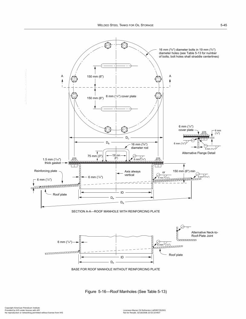
WELDED STEEL TANKS FOR OIL STORAGE 5-45
Copyright AmericaProvided by IHS uNo reproduction o
Figure 5-16—Roof Manholes (See Table 5-13)
150 mm (6")
150 mm (6")
A
16 mm (5/8") diameter bolts in 19 mm (3/4")diameter holes (see Table 5-13 for numberof bolts; bolt holes shall straddle centerlines)
A
6 mm (1/4") cover plate
DB 16 mm (5/8")diameter rod
DC
DP
DR
ID
6 mm (1/4")
6 mm (1/4")
6 mm (1/4")
Axis alwaysvertical
or 150 mm (6") min
6 mm (1/4")cover plate
ID
DP
Roof plate
SECTION A-A—ROOF MANHOLE WITH REINFORCING PLATE
BASE FOR ROOF MANHOLE WITHOUT REINFORCING PLATE
Alternative Neck-to-Roof-Plate Joint
Roof plate
6 mm (1/4")
6 mm (1/4")
6 mm (1/4")
6 mm(1/4")
6 mm (1/4")
5 mm (3/16")
5 mm (3/16")
150 mm(6")
75 mm (3")
Reinforcing plate
1.5 mm (1/16")thick gasket
Alternative Flange Detail
--``,,,,,,`,,`,`,`,``,,````,,``-`-`,,`,,`,`,,`---
n Petroleum Institute nder license with API Licensee=Bazan Oil Refineries Ltd/5957352001
Not for Resale, 02/18/2008 23:53:18 MSTr networking permitted without license from IHS

5-46 API STANDARD 650
•
Copyright AmProvided by No reproduc
5.8.7 Water Drawoff Sumps
Water drawoff sumps shall be as specified in Figure 5-21 and Table 5-16, unless otherwise specified by the Purchaser.
5.8.8 Scaffold-Cable Support
The scaffold-cable support shall conform to Figure 5-22. Where seams or other attachments are located at the center of the tankroof, the scaffold support shall be located as close as possible to the center.
5.8.9 Threaded Connections
Threaded piping connections shall be female and tapered. The threads shall conform to the requirements of ASME B1.20.1 fortapered pipe threads.
Table 5-13—Dimensions for Roof Manholes (mm [in.])
Column 1 Column 2 Column 3 Column 4 Column 5 Column 6 Column 7 Column 8 Column 9
Size of Manhole
Diameterof Neck
IDa
Diameterof Cover
PlateDC
Diameterof BoltCircle
DB
Numberof Bolts
Diameter of Gasket
Diameter of Hole in Roof
Plate or Reinforcing
PlateDP
Outside Diameter of Reinforcing
PlateDRInside Outside
500 (20) 500 (20) 650 (26) 590 (231/2) 16 500 (20) 650 (26) 515 (205/8) 1050 (42)
600 (24) 600 (24) 750 (30) 690 (271/2) 20 600 (24) 750 (30) 615 (245/8) 1150 (46)
aPipe may be used for neck, providing the minimum nominal wall thickness is 6 mm (1/4 in.). (ID and Dp shall be adjusted accordingly.)Note: See Figure 5-18.
Table 5-14—Dimensions for Flanged Roof Nozzles (mm [in.])
Column 1 Column 2 Column 3 Column 4 Column 5
NozzleNPS
Outside Diameterof Pipe Neck
Diameter of Hole in Roof Plate or Reinforcing Plate
DP
Minimum Heightof Nozzle
HR
Outside Diameter of Reinforcing Platea
DR
11/2 48.3 (1.900) 50 (2) 150 (6) 125 (5)
2 60.3 (23/8) 65 (21/2) 150 (6) 175 (7)
3 88.9 (31/2) 92 (35/8) 150 (6) 225 (9)
4 114.3 (41/2) 120 (45/8) 150 (6) 275 (11)
6 168.3 (65/8) 170 (63/4) 150 (6) 375 (15)
8 219.1 (85/8) 225 (87/8) 150 (6) 450 (18)
10 273.0 (103/4) 280 (11) 200 (8) 550 (22)
12 323.8 (123/4) 330 (13) 200 (8) 600 (24)
aReinforcing plates are not required on nozzles NPS 6 or smaller but may be used if desired.Note: See Figure 5-19.
--``,,,,,,`,,`,`,`,``,,````,,``-`-`,,`,,`,`,,`---
erican Petroleum Institute IHS under license with API Licensee=Bazan Oil Refineries Ltd/5957352001
Not for Resale, 02/18/2008 23:53:18 MSTtion or networking permitted without license from IHS

WELDED STEEL TANKS FOR OIL STORAGE 5-47
•
07
••
Copyright AmericaProvided by IHS uNo reproduction o
5.8.10 Platforms, Walkways, and Stairways
a. Platforms, walkways, and stairways shall be in accordance with Tables 5-17, 5-18, and 5-19 and OSHA 29 CFR 1910, Subpart D,or equivalent national safety standard and the requirements herein, except as noted herein.b. For examples of acceptable details, see Process Industry Practices standard details PIP STF05501, PIP STF05520, and PIPSTF05521 (see www.pip.org). c. Unless declined on the Data Sheet, Line 24, a roof edge landing or gauger’s platform shall be provided at the top of all tanks.
5.8.11 Other Appurtenances and Attachments
5.8.11.1 Floating suction lines shall be provided when specified on the Data Sheet, Table 4. Floating suction lines using rigidarticulated (having one or more swing joints) pipe shall be designed to travel in a vertical plane and prevent damage to the floatingroof and the suction line through its design range of travel. These lines shall be designed so that the vertical plane is as close aspossible to, and in no case greater than 10 degrees off, a radial line from the tank centerline to the nozzle. Adjustments shall bemade to clear internal structures.
5.8.11.2 Inlet diffusers shall be provided if requested in the Other Tank Appurtenances section of the Data Sheet, Table 4. (SeeAPI RP 2003 and Appendix H for additional information.)
5.8.11.3 If required by the Purchaser, grounding lugs shall be provided in the quantity specified on the Data Sheet, Table 4, andcomply with Figure 5-23. The lugs shall be equally spaced around the base of the tank. Provide a minimum of four lugs. The sug-gested maximum lug spacing is 30 m (100 ft).
Note: Tanks that rest directly on a foundation of soil, asphalt or concrete are inherently grounded for purposes of dissipation of electrostaticcharges. The addition of grounding rods or similar devices will not reduce the hazard associated with electrostatic charges in the stored product.API RP 2003 and NFPA-780 contain additional information about tank grounding issues as well as comments about lightning protection.
5.8.11.4 All non-circular miscellaneous pads shall have rounded corners with a minimum radius of 50 mm (2 in.). Pads thatmust cover shell seams shall be provided with a 6 mm (1/4 in.) telltale hole (see 5.7.3.4).
Table 5-15—Dimensions for Threaded Roof Nozzles (mm [in.])
Column 1 Column 2 Column 3 Column 4
NozzleNPS
CouplingNPS
Diameter of Hole in Roof Plateor Reinforcing Plate
DP
Outside Diameter of Reinforcing Platea
DR
3/4 3/4 36 (17/16) 100 (4)
1 1 44 (123/32) 110 (41/2)
11/2 11/2 60 (211/32) 125 (5)
2 2 76 (3) 175 (7)
3 3 105 (41/8) 225 (9)
4 4 135 (511/32) 275 (11)
6 6 192 (717/32) 375 (15)
8 8 250 (97/8) 450 (18)
10 10 305 (12) 550 (22)
12 12 360 (141/4) 600 (24)
aReinforcing plates are not required on nozzles NPS 6 or smaller but may be used if desired.Note: See Figure 5-20.
--``,,,,,,`,,`,`,`,``,,````,,``-`-`,,`,,`,`,,`---
n Petroleum Institute nder license with API Licensee=Bazan Oil Refineries Ltd/5957352001
Not for Resale, 02/18/2008 23:53:18 MSTr networking permitted without license from IHS
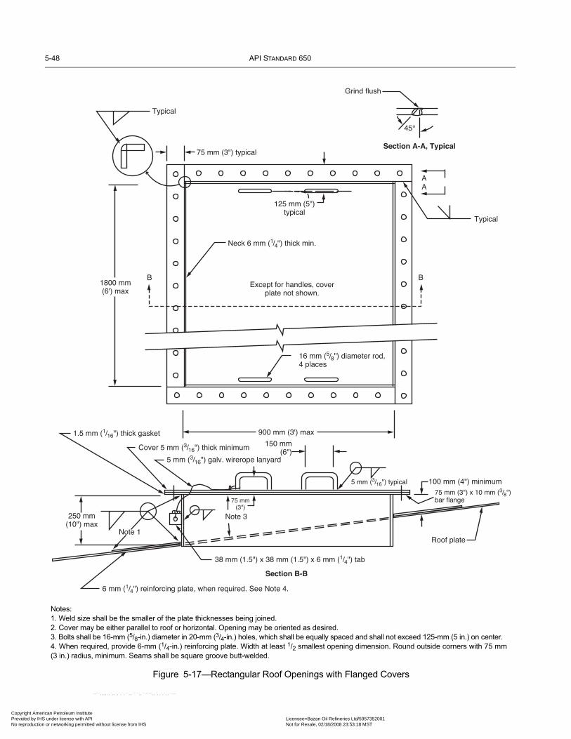
5-48 API STANDARD 650
Copyright AmProvided by No reproduc
Figure 5-17—Rectangular Roof Openings with Flanged Covers
Typical
75 mm (3") typical
45°
Grind flush
Section A-A, Typical
AA
125 mm (5")typical
Neck 6 mm (1/4") thick min.
16 mm (5/8") diameter rod,4 places
Except for handles, coverplate not shown.
1800 mm(6') max
900 mm (3') max
B B
Typical
1.5 mm (1/16") thick gasket
Cover 5 mm (3/16") thick minimum
5 mm (3/16") galv. wirerope lanyard
250 mm(10") max
Note 1
6 mm (1/4") reinforcing plate, when required. See Note 4.
38 mm (1.5") x 38 mm (1.5") x 6 mm (1/4") tab
Section B-B
Note 3
75 mm(3")
150 mm(6")
5 mm (3/16") typical 100 mm (4") minimum75 mm (3") x 10 mm (3/8")bar flange
Roof plate
Notes:1. Weld size shall be the smaller of the plate thicknesses being joined.2. Cover may be either parallel to roof or horizontal. Opening may be oriented as desired.3. Bolts shall be 16-mm (5/8-in.) diameter in 20-mm (3/4-in.) holes, which shall be equally spaced and shall not exceed 125-mm (5 in.) on center.4. When required, provide 6-mm (1/4-in.) reinforcing plate. Width at least 1/2 smallest opening dimension. Round outside corners with 75 mm(3 in.) radius, minimum. Seams shall be square groove butt-welded.
--``,,,,,,`,,`,`,`,``,,````,,``-`-`,,`,,`,`,,`---
erican Petroleum Institute IHS under license with API Licensee=Bazan Oil Refineries Ltd/5957352001
Not for Resale, 02/18/2008 23:53:18 MSTtion or networking permitted without license from IHS

WELDED STEEL TANKS FOR OIL STORAGE 5-49
07
Copyright AmericaProvided by IHS uNo reproduction o
--``,,,,,,`,,`,`,`,``,,````,,``-`-`,,`,,`,`,,`---
5.9 TOP AND INTERMEDIATE STIFFENING RINGS
5.9.1 GeneralAn open-top tank shall be provided with stiffening rings to maintain roundness when the tank is subjected to wind loads. The stiff-ening rings shall be located at or near the top of the top course, preferably on the outside of the tank shell. This design for ringsused as wind girders also applies to floating-roof tanks covered in Appendix C. The top angle and the wind girders shall conform,in material and size, to the requirements of this Standard.
Figure 5-18—Rectangular Roof Openings with Hinged Cover
Typical
Neck 6 mm (1/4") thick min.
16 mm (5/8") diameter rod handle, 1 place for 900 mm (3') or less cover, 2 places at 1/4-points for larger openings
1800 mm(6') max
900 mm (3') max
250 mm(10") max
Note 1
Elevation
Plan
Note 2
125 mm (5")
5 mm (3/16") minimum thick cover 50 mm (2")
100 mm (4") minimum
Roof plate
5 mm (3/16") typical
150 mm(6")
Provide 2 lock tabs for openingslarger than 900 mm (3')
50 mm (2") typical
5 mm(3/16")
Fabricate hinges from NPS 1 SCH 40 pipe and 22 mm (7/8") rod, minimum 2 each, maximum 600 mm (2') O.C., equally spaced.
75 mm(3")
6 mm(1/4")min.
Notes:1. Weld size shall be the smaller of the plate thicknesses being joined.2. Cover may be either parallel to roof or horizontal. Opening may be oriented as desired.3. Reinforcement, when required, shall be as shown in Figure 5-19.4. Not for use on roofs designed to contain internal pressure.
n Petroleum Institute nder license with API Licensee=Bazan Oil Refineries Ltd/5957352001
Not for Resale, 02/18/2008 23:53:18 MSTr networking permitted without license from IHS

5-50 API STANDARD 650
•07
Copyright AmProvided by No reproduc
5.9.2 Types of Stiffening RingsStiffening rings may be made of structural sections, formed plate sections, sections built up by welding, or combinations of suchtypes of sections assembled by welding. The outer periphery of stiffening rings may be circular or polygonal (see Figure 5-24).
5.9.3 Restrictions on Stiffening Rings
5.9.3.1 The minimum size of angle for use alone or as a component in a built-up stiffening ring shall be 64 × 64 × 6.4 mm (21/2× 21/2 × 1/4 in.). The minimum nominal thickness of plate for use in formed or built-up stiffening rings shall be 6 mm (1/4 in.).
5.9.3.2 When the stiffening rings are located more than 0.6 m (2 ft) below the top of the shell, the tank shall be provided with a64 × 64 × 4.8 mm (21/2 × 21/2 × 3/16 in.) top curb angle for shells 5 mm (3/16 in.) thick, with a 76 × 76 × 6.4 mm (3 × 3 × 1/4 in.)angle for shells more than 5 mm (3/16 in.) thick, or with other members of equivalent section modulus.
5.9.3.3 Rings that may trap liquid shall be provided with adequate drain holes. Uninsulated tanks having rings shall have smallwater-shedding slopes and/or drain holes or slots unless the Purchaser approves an alternate means of drainage. If drain holes areprovided, they shall be at least 25 mm (1 in.) diameter (or slot width) on 2400 mm (8 ft) centers or less. Insulated tanks where therings function as insulation closures shall have no drain holes or slots.
5.9.3.4 Welds joining stiffening rings to the tank shell may cross vertical tank seam welds. Any splice weld in the ring shall belocated a minimum of 150 mm (6 in.) from any vertical shell weld. Stiffening rings may also cross vertical tank seam welds withthe use of coping (rat hole) of the stiffening ring at the vertical tank seam. Where the coping method is used, the required sectionmodulus of the stiffening ring and weld spacing must be maintained.
Figure 5-19—Flanged Roof Nozzles (See Table 5-14)
Figure 5-20—Threaded Roof Nozzles (See Table 5-15)
DR
Axis alwaysvertical
AlternativeNeck-to-Roof-Plate
Joint
Roof plate
BASE FOR NOZZLE WITHOUT REINFORCING PLATE
Axis alwaysvertical
Roof plate6 mm(1/4")
6 mm (1/4")6 mm(1/4")
5 mm(3/16")
DP
DP
Plain or raised-faceslip-on welding, welding-neck,or plate ring flange
(See note)
Standard-weight line pipe
HR
NOZZLE WITH REINFORCING PLATE
Note: When the roof nozzle is used for venting, the neck shall be trimmed flush with the roofline.
6 mm (1/4")6 mm (1/4")
6 mm (1/4")5 mm (3/16")
Roof plate
NOZZLE WITHOUT REINFORCING PLATE
Axis alwaysvertical
Roof plate
DP
(See note)
NOZZLE WITH REINFORCING PLATE
DRDP
Axis always vertical
Pipe coupling
Note: See 5.8.9 for requirements for threaded connections. When the roof nozzle is used for venting, the neck shall be trimmed flush with the roofline.
erican Petroleum Institute IHS under license with API Licensee=Bazan Oil Refineries Ltd/5957352001
Not for Resale, 02/18/2008 23:53:18 MSTtion or networking permitted without license from IHS
--``,,,,,,`,,`,`,`,``,,````,,``-`-`,,`,,`,`,,`---

WELDED STEEL TANKS FOR OIL STORAGE 5-51
Copyright AmericaProvided by IHS uNo reproduction o
Figure 5-21—Drawoff Sump (See Table 5-16)
Figure 5-22—Scaffold Cable Support
Table 5-16—Dimensions for Drawoff Sumps
NPS
Diameter of Sumpmm (in.)
A
Depth of Sumpmm (in.)
B
Distance fromCenter Pipe to Shell
m (ft)C
Thickness of Platesin Sumpmm (in.)
t
Minimum InternalPipe Thickness
mm (in.)
Minimum NozzleNeck Thickness
mm (in.)2 610 (24) 300 (12) 1.1 (31/2) 8 (5/16) 5.54 (0.218) 5.54 (0.218)
3 910 (36) 450 (18) 1.5 (5) 10 (3/8) 6.35 (0.250) 7.62 (0.300)
4 1220 (48) 600 (24) 2.1 (63/4) 10 (3/8) 6.35 (0.250) 8.56 (0.337)
6 1520 (60) 900 (36) 2.6 (81/2) 11 (7/16) 6.35 (0.250) 10.97 (0.432)
Note: See Figure 5-19.
Details a1–a4(all are acceptable)
150 mm(6") min
a1 a2
Detail b Detail c
60° a4a3
C
B1 pipe
diameter (min)
A
t
t
t
Tank bottomSee Details a1–a4
See Detailb, c, or d
Tank shell
Nozzle neck
Tack-weldbackup barto flange
6 mm (1/4")
6 mm (1/4") 6 mm (1/4") 8 mm (5/16")
8 mm (5/16")
Internal pipe
Full-fillet weld
Detail d
Note: The erection procedure shall include the following steps: (a) a hole shall be cut in the bottom plate or a sump shall be placed in thefoundation before bottom placement; (b) a neat excavation shall be made to conform to the shape of the drawoff sump, the sump shall be putin place, and the foundation shall be compacted around the sump after placement; and (c) the sump shall be welded to the bottom.
150 mm (6")diameter
Schedule 40pipe (see note)
150 mm (6")
230 mm (9") diameter
135 mm (51/4") ID
10 mm (3/8")formed plate
6 mm (1/4") plate
6 mm (1/4")
8 mm (5/16")
6 mm (1/4")
Tank roof
Note: NPS 4 Schedule 40 pipe(wall thickness = 6.02 mm[0.237 in.]; outside diameter =114.3 mm [4.5 in.]).
--``,,,,,,`,,`,`,`,``,,````,,``-`-`,,`,,`,`,,`---
n Petroleum Institute nder license with API Licensee=Bazan Oil Refineries Ltd/5957352001
Not for Resale, 02/18/2008 23:53:18 MSTr networking permitted without license from IHS
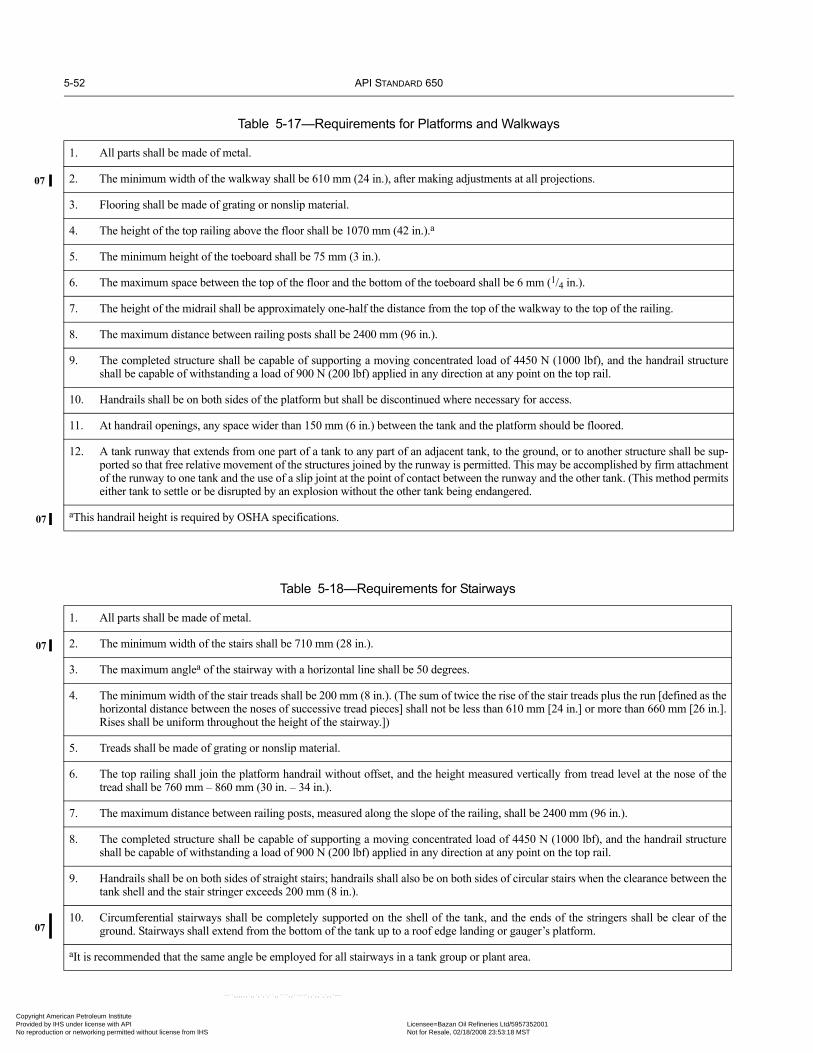
5-52 API STANDARD 650
07
07
07
07
Copyright AmProvided by No reproduc
Table 5-17—Requirements for Platforms and Walkways
1. All parts shall be made of metal.
2. The minimum width of the walkway shall be 610 mm (24 in.), after making adjustments at all projections.
3. Flooring shall be made of grating or nonslip material.
4. The height of the top railing above the floor shall be 1070 mm (42 in.).a
5. The minimum height of the toeboard shall be 75 mm (3 in.).
6. The maximum space between the top of the floor and the bottom of the toeboard shall be 6 mm (1/4 in.).
7. The height of the midrail shall be approximately one-half the distance from the top of the walkway to the top of the railing.
8. The maximum distance between railing posts shall be 2400 mm (96 in.).
9. The completed structure shall be capable of supporting a moving concentrated load of 4450 N (1000 lbf), and the handrail structureshall be capable of withstanding a load of 900 N (200 lbf) applied in any direction at any point on the top rail.
10. Handrails shall be on both sides of the platform but shall be discontinued where necessary for access.
11. At handrail openings, any space wider than 150 mm (6 in.) between the tank and the platform should be floored.
12. A tank runway that extends from one part of a tank to any part of an adjacent tank, to the ground, or to another structure shall be sup-ported so that free relative movement of the structures joined by the runway is permitted. This may be accomplished by firm attachmentof the runway to one tank and the use of a slip joint at the point of contact between the runway and the other tank. (This method permitseither tank to settle or be disrupted by an explosion without the other tank being endangered.
aThis handrail height is required by OSHA specifications.
Table 5-18—Requirements for Stairways
1. All parts shall be made of metal.
2. The minimum width of the stairs shall be 710 mm (28 in.).
3. The maximum anglea of the stairway with a horizontal line shall be 50 degrees.
4. The minimum width of the stair treads shall be 200 mm (8 in.). (The sum of twice the rise of the stair treads plus the run [defined as thehorizontal distance between the noses of successive tread pieces] shall not be less than 610 mm [24 in.] or more than 660 mm [26 in.].Rises shall be uniform throughout the height of the stairway.])
5. Treads shall be made of grating or nonslip material.
6. The top railing shall join the platform handrail without offset, and the height measured vertically from tread level at the nose of thetread shall be 760 mm – 860 mm (30 in. – 34 in.).
7. The maximum distance between railing posts, measured along the slope of the railing, shall be 2400 mm (96 in.).
8. The completed structure shall be capable of supporting a moving concentrated load of 4450 N (1000 lbf), and the handrail structureshall be capable of withstanding a load of 900 N (200 lbf) applied in any direction at any point on the top rail.
9. Handrails shall be on both sides of straight stairs; handrails shall also be on both sides of circular stairs when the clearance between thetank shell and the stair stringer exceeds 200 mm (8 in.).
10. Circumferential stairways shall be completely supported on the shell of the tank, and the ends of the stringers shall be clear of theground. Stairways shall extend from the bottom of the tank up to a roof edge landing or gauger’s platform.
aIt is recommended that the same angle be employed for all stairways in a tank group or plant area.
erican Petroleum Institute IHS under license with API Licensee=Bazan Oil Refineries Ltd/5957352001
Not for Resale, 02/18/2008 23:53:18 MSTtion or networking permitted without license from IHS
--``,,,,,,`,,`,`,`,``,,````,,``-`-`,,`,,`,`,,`---

WELDED STEEL TANKS FOR OIL STORAGE 5-53
07
Copyright AmericaProvided by IHS uNo reproduction o
--``,,,,,,`,
Table 5-19—Rise, Run, and Angle Relationships for Stairways
Height of Risemm (in.)
R
2R + r = 610 mm (24 in.) 2R + r = 660 mm (26 in.)Width of Run
mm (in.)r
Angle Width of Runmm (in.)
r
Angle
Degrees Minutes Degrees Minutes135 (51/4) 340 (131/2) 21 39 — — —140 (51/2) 330 (13) 22 59 380 (15) 20 13145 (53/4) 320 (121/2) 24 23 370 (141/2) 21 24150 (6) 310 (12) 25 49 360 (14) 22 37155 (61/4) 300 (111/2) 27 19 350 (131/2) 23 53165 (61/2) 280 (11) 30 31 330 (13) 26 34170 (63/4) 270 (101/2) 32 12 320 (121/2) 27 59180 (7) 250 (10) 35 45 300 (12) 30 58185 (71/4) 240 (91/2) 37 38 290 (111/2) 32 32190 (71/2) 230 (9) 39 34 280 (11) 34 10195 (73/4) 220 (81/2) 41 33 270 (101/2) 35 50205 (8) 200 (8) 45 42 250 (10) 39 21210 (81/4) 190 (71/2) 47 52 240 (91/2) 41 11215 (81/2) — — — 230 (9) 43 4220 (83/4) — — — 220 (81/2) 45 0225 (9) — — — 210 (8) 46 58
Figure 5-23—Grounding Lug
Notes:1. Lug material shall be austenitic stainless
steel when attached to carbon or low alloy steel parts. When attached to other materials, lug material shall be similar to the material to which attached.
2. See tank drawing/data sheet for elevation and orientation.
3. Drawing courtesy of PIP (Process Industry Practices).
DO NOT PAINT
2"
Shell
1"
C 9/16" Diameter hole
11/ 4
"1
1/ 4
"
3/16"
1/4" thick.See Note 1
Radius corners
Insulation(if required)
21/ 2
"
L
[SI units omitted for clarity]
,`,`,`,``,,````,,``-`-`,,`,,`,`,,`---
n Petroleum Institute nder license with API Licensee=Bazan Oil Refineries Ltd/5957352001
Not for Resale, 02/18/2008 23:53:18 MSTr networking permitted without license from IHS

5-54 API STANDARD 650
Copyright AmProvided by No reproduc
Figure 5-24—Typical Stiffening-Ring Sections for Tank Shells (See Table 5-20)
16t
Detail c
Detail e
16t
25 mm (1")
16t
16t
16t
16t
16t
16t
150 mm (6")
b
t
t
t
65 mm (21/2")
6 mm (1/4")
tt
Detail a Detail b
Detail d
Note: The section moduli given in Table 5-20 for Details c and d are based on the longerleg being located horizontally (perpendicular to the shell) when angles with uneven legsare used.
--``,,,,,,`,,`,`,`,``,,````,,``-`-`,,`,,`,`,,`---
erican Petroleum Institute IHS under license with API Licensee=Bazan Oil Refineries Ltd/5957352001
Not for Resale, 02/18/2008 23:53:18 MSTtion or networking permitted without license from IHS

WELDED STEEL TANKS FOR OIL STORAGE 5-55
Copyright AmericaProvided by IHS uNo reproduction o
--``,,,,,,`,,`,`,`,``,,````,,``-`-`,,`,,`,`,,`---
Table 5-20—Section Moduli (cm3 [in.3]) of Stiffening-Ring Sections on Tank Shells
Column 1 Column 2 Column 3 Column 4 Column 5 Column 6
Member Size Shell Thickness (mm [in.])
mm in. 5 (3/16) 6 (1/4) 8 (5/16) 10 (3/8) 11 (7/16)
Top Angle: Figure 5-24, Detail a64 × 64 × 6.4 21/2 × 21/2 × 1/4 6.86 (0.41) 7.01 (0.42) — — —64 × 64 × 7.9 21/2 × 21/2 × 5/16 8.30 (0.51) 8.48 (0.52) — — —76 × 76 × 9.5 3 × 3 × 3/8 13.80 (0.89) 14.10 (0.91) — — —
Curb Angle: Figure 5-24, Detail b64 × 64 × 6.4 21/2 × 21/2 × 1/4 27.0 (1.61) 28.3 (1.72) — — —64 × 64 × 7.9 21/2 × 21/2 × /16 31.1 (1.89) 32.8 (2.04) — — —76 × 76 × 6.4 3 × 3 × 1/4 38.1 (2.32) 39.9 (2.48) — — —76 × 76 × 9.5 3 × 3 × 3/8 43.0 (2.78) 52.6 (3.35) — — —102 × 102 × 6.4 4 × 4 × 1/4 57.6 (3.64) 71.4 (4.41) — — —102 × 102 × 9.5 4 × 4 × 3/8 65.6 (4.17) 81.4 (5.82) — — —
One Angle: Figure 5-24, Detail c (See Note)64 × 64 × 6.4 21/2 × 21/2 × 1/4 28.5 (1.68) 29.6 (1.79) 31.3 (1.87) 32.7 (1.93) 33.4 (2.00)64 × 64 × 7.9 21/2 × 21/2 × 5/16 33.1 (1.98) 34.6 (2.13) 36.9 (2.23) 38.7 (2.32) 39.5 (2.40)102 × 76 × 6.4 4 × 3 × 1/4 58.3 (3.50) 60.8 (3.73) 64.2 (3.89) 66.6 (4.00) 67.7 (4.10)102 × 76 × 7.9 4 × 3 × 5/16 68.3 (4.14) 71.6 (4.45) 76.2 (4.66) 79.4 (4.82) 80.8 (4.95)127 × 76 × 7.9 5 × 3 × 5/16 90.7 (5.53) 95.2 (5.96) 102.0 (6.25) 106.0 (6.47) 108.0 (6.64)127 × 89 × 7.9 5 × 31/2 × 5/16 101.0 (6.13) 106.0 (6.60) 113.0 (6.92) 118.0 (7.16) 120.0 (7.35)127 × 89 × 9.5 5 × 31/2 × 3/8 116.0 (7.02) 122.0 (7.61) 131.0 (8.03) 137.0 (8.33) 140.0 (8.58)152 × 102 × 9.5 6 × 4 × 3/8 150.0 (9.02) 169.0 (10.56) 182.0 (11.15) 191.0 (11.59) 194.0 (11.93)
Two Angles: Figure 5-24, Detail d (See Note)102 × 76 × 7.9 4 × 3 × 5/16 186 (11.27) 191 (11.78) 200 (12.20) 207 (12.53) 210 (12.81)102 × 76 × 9.5 4 × 3 × 3/8 216 (13.06) 222 (13.67) 233 (14.18) 242 (14.60) 245 (14.95)127 × 76 × 7.9 5 × 3 × 5/16 254 (15.48) 262 (16.23) 275 (16.84) 285 (17.34) 289 (17.74)127 × 76 × 9.5 5 × 3 × 3/8 296 (18.00) 305 (18.89) 321 (19.64) 333 (20.26) 338 (20.77)127 × 89 × 7.9 5 × 31/2 × 5/16 279 (16.95) 287 (17.70) 300 (18.31) 310 (18.82) 314 (19.23)127 × 89 × 9.5 5 × 31/2 × 3/8 325 (19.75) 334 (20.63) 350 (21.39) 363 (22.01) 368 (22.54)152 × 102 × 9.5 6 × 4 × 3/8 456 (27.74) 468 (28.92) 489 (29.95) 507 (30.82) 514 (31.55)
Formed Plate: Figure 5-24, Detail eb = 250 b = 10 — 341 (23.29) 375 (24.63) 392 (25.61) 399 (26.34)b = 300 b = 12 — 427 (29.27) 473 (31.07) 496 (32.36) 505 (33.33)b = 350 b = 14 — 519 (35.49) 577 (37.88) 606 (39.53) 618 (40.78)b = 400 b = 16 — 615 (42.06) 687 (45.07) 723 (47.10) 737 (48.67)b = 450 b = 18 — 717 (48.97) 802 (52.62) 846 (55.07) 864 (56.99)b = 500 b = 20 — 824 (56.21) 923 (60.52) 976 (63.43) 996 (65.73)b = 550 b = 22 — 937 (63.80) 1049 (68.78) 1111 (72.18) 1135 (74.89)b = 600 b = 24 — 1054 (71.72) 1181 (77.39) 1252 (81.30) 1280 (84.45)b = 650 b = 26 — 1176 (79.99) 1317 (86.35) 1399 (90.79) 1432 (94.41)b = 700 b = 28 — 1304 (88.58) 1459 (95.66) 1551 (100.65) 1589 (104.77)b = 750 b = 30 — 1436 (97.52) 1607 (105.31) 1709 (110.88) 1752 (115.52)b = 800 b = 32 — 1573 (106.78) 1759 (115.30) 1873 (121.47) 1921 (126.66)b = 850 b = 34 — 1716 (116.39) 1917 (125.64) 2043 (132.42) 2096 (138.17)b = 900 b = 36 — 1864 (126.33) 2080 (136.32) 2218 (143.73) 2276 (150.07)b = 950 b = 38 — 2016 (136.60) 2248 (147.35) 2398 (155.40) 2463 (162.34)b = 1000 b = 40 — 2174 (147.21) 2421 (158.71) 2584 (167.42) 2654 (174.99)
Note: The section moduli for Details c and d are based on the longer leg being located horizontally (perpendicular to the shell) when angles with uneven legs are used.
n Petroleum Institute nder license with API Licensee=Bazan Oil Refineries Ltd/5957352001
Not for Resale, 02/18/2008 23:53:18 MSTr networking permitted without license from IHS

5-56 API STANDARD 650
•
Copyright AmProvided by No reproduc
5.9.4 Stiffening Rings as WalkwaysA stiffening ring or any portion of it that is specified as a walkway shall have a width not less than 710 mm (28 in.) clear of pro-jections including the angle on the top of the tank shell. The clearance around local projections shall not be less than 610 mm(24 in.). Unless the tank is covered with a fixed roof, the stiffening ring (used as a walkway) shall be located 1100 mm (42 in.)below the top of the curb angle and shall be provided with a standard railing on the unprotected side and at the ends of the sectionused as a walkway.
5.9.5 Supports for Stiffening RingsSupports shall be provided for all stiffening rings when the dimension of the horizontal leg or web exceeds 16 times the leg orweb thickness. The supports shall be spaced at the intervals required for the dead load and vertical live load; however, the spacingshall not exceed 24 times the width of the outside compression flange.
5.9.6 Top Wind Girder
5.9.6.1 The required minimum section modulus of the stiffening ring shall be determined by the following equation:
In SI units:
whereZ = required minimum section modulus (cm3),D = nominal tank diameter (m),
H2 = height of the tank shell (m), including any freeboard provided above the maximum filling height as a guide for a floating roof,
V = design wind speed (3-sec gust) (km/h) (see 5.2.1[j]).
In US Customary units:
Z = 0.0001 D2 H2
whereZ = required minimum section modulus (in.3),D = nominal tank diameter (ft),
H2 = height of the tank shell (ft), including any freeboard provided above the maximum filling height as a guide for a floating roof,
V = design wind speed (3-sec gust) (mph) (see 5.2.1[j]).
Note: For tank diameters over 60 m (200 ft), the section modulus required by the equation may be reduced by agreement between the Purchaserand the Manufacturer, but the modulus may not be less than that required for a tank diameter of 60 m (200 ft). (A description of the loads on thetank shell that are included in the design wind speed can be found in Item a of the note to 5.9.7.1.)
5.9.6.2 The section modulus of the stiffening ring shall be based on the properties of the applied members and may include aportion of the tank shell for a distance of 16 plate thicknesses below and, if applicable, above the shell-ring attachment. Whencurb angles are attached to the top edge of the shell ring by butt-welding, this distance shall be reduced by the width of the verticalleg of the angle (see Figure 5-24 and Table 5-22).
5.9.6.3 When a stair opening is installed through a stiffening ring, the section modulus of the portion of the ring outside theopening, including the transition section, shall conform to the requirements of 5.9.6.1. The shell adjacent to the opening shall bestiffened with an angle or a bar, the wide side of which is placed in a horizontal plane. The other sides of the opening shall also bestiffened with an angle or a bar, the wide side of which is placed in a vertical plane. The cross-sectional area of these rim stiffenersshall be greater than or equal to the cross-sectional area of the portion of shell included in the section-modulus calculations for thestiffening ring. These rim stiffeners or additional members shall provide a suitable toe board around the opening.The stiffening members shall extend beyond the end of the opening for a distance greater than or equal to the minimum depth ofthe regular ring sections. The end stiffening members shall frame into the side stiffening members, and the end and side stiffeningmembers shall be connected to ensure that their full strength is developed. Figure 5-25 shows the opening described in this sec-tion. Alternative details that provide a load-carrying capacity equal to that of the girder cross-section away from the opening maybe provided.
ZD2H2
17------------- V
190---------⎝ ⎠⎛ ⎞
2
=
V120---------⎝ ⎠⎛ ⎞
2
--``,,,,,,`,,`,`,`,``,,````,,``-`-`,,`,,`,`,,`---
erican Petroleum Institute IHS under license with API Licensee=Bazan Oil Refineries Ltd/5957352001
Not for Resale, 02/18/2008 23:53:18 MSTtion or networking permitted without license from IHS

WELDED STEEL TANKS FOR OIL STORAGE 5-57
•
Copyright AmericaProvided by IHS uNo reproduction o
5.9.7 Intermediate Wind Girders
5.9.7.1 The maximum height of the unstiffened shell shall be calculated as follows:
In SI units:
where
H1 = vertical distance, in m, between the intermediate wind girder and the top angle of the shell or the top wind girder of an open-top tank,
t = as ordered thickness, unless otherwise specified, of the top shell course (mm) (see Note 1),
D = nominal tank diameter (m),
V = design wind speed (3-sec gust) (km/h) (see 5.2.1[j]).
In US Customary units:
Figure 5-25—Stairway Opening through Stiffening Ring
bmin
D
D
C
CB
B
A
A
bmin
Bar e Bar d
a
Bar c
t st R
Up
b
Notes:1. The cross-sectional area of a, c, d, and e must equal 32ts2. The section of the figure designated “a” may be a bar
or an angle whose wide leg is horizontal. The other sections may be bars or angles whose wide legs are vertical.2. Bars c, d, and e may be placed on the top of the girder web, provided they do not create a tripping hazard.3. The section modulus of Sections A-A, B-B, C-C, and D-D shall conform to 5.9.6.1.4. The stairway may be continuous through the wind girder or may be offset to provide a landing.5. See 5.9.6.3 for toeboard requirements.
H1 9.47t tD----⎝ ⎠⎛ ⎞
3 190V
---------⎝ ⎠⎛ ⎞
2
=
H1 600,000t tD----⎝ ⎠⎛ ⎞
3 120V
---------⎝ ⎠⎛ ⎞
2
=
n Petroleum Institute nder license with API Licensee=Bazan Oil Refineries Ltd/5957352001
Not for Resale, 02/18/2008 23:53:18 MSTr networking permitted without license from IHS
--``,,,,,,`,,`,`,`,``,,````,,``-`-`,,`,,`,`,,`---

5-58 API STANDARD 650
•
•
••
Copyright AmProvided by No reproduc
--``,,,,,,`,,`,`,`,``,,````,,``-`-`,,`,,`,`,,`---
where
H1 = vertical distance, in ft, between the intermediate wind girder and the top angle of the shell or the top wind girder of an open-top tank,
t = as ordered thickness, unless otherwise specified, of the top shell course (in.) (see Note 1),
D = nominal tank diameter (ft),
V = design wind speed (3-sec gust) (mph) (see 5.2.1[j]).Note 1: The structural stability check of wind girder stiffened shells in accordance with 5.9.6 and 5.9.7, shall be based upon nominal dimensionsof the shell course and the wind girders irrespective of specified corrosion allowances whenever the “No” option is selected for “Check Buck-ling in Corroded Cond.?” on the Data Sheet, Line 9. Whenever the “Yes” option is selected, the check must be based upon the nominal dimen-sions minus the specified corrosion allowance.Note 2: This formula is intended to cover tanks with either open tops or closed tops and is based on the following factors (for the background forthe factors given in this note, see ASCE 7 and R. V. McGrath’s “Stability of API Standard 650 Tank Shells”):19
a. The velocity pressure is:
p = 0.00256Kz Kzt Kd V 2 I G = 1.48 kPa (31 lbf/ft2)
where
Kz = velocity pressure exposure coefficient = 1.04 for exposure C at a height of 40 ft,
Kzt = 1.0 for all structures except those on isolated hills or escarpments,
Kd = directionality factor = 0.95 for round tanks,
V = 3-second gust design wind speed = 190 km/h (120 mph) at 10 m (33 ft) above ground (see 5.2.1[j]),
I = importance factor = 1.0 for Category II structures,
G = gust factor = 0.85 for exposure C.
A 0.24 kPa (5 lbf/ft2) internal vacuum is added for inward drag on open-top tanks or for external pressure on closed top tanks for a total of1.72 kPa (36 lbf/ft2).
b. The wind pressure is uniform over the theoretical buckling mode of the tank shell, which eliminates the need for a shape factor for the windloading.c. The modified U.S. Model Basin formula for the critical uniform external pressure on thin-wall tubes free from end loadings, subject to thetotal pressure specified in Item a.d. When other factors are specified by the Purchaser that are greater than the factors in Items a – c, the total load on the shell shall be modifiedaccordingly, and H1 shall be decreased by the ratio of 1.72 kPa (36 lbf/ft2) to the modified total pressure.
5.9.7.2 After the maximum height of the unstiffened shell, H1, has been determined, the height of the transformed shell shall becalculated as follows:
a. With the following equation, change the actual width of each shell course into a transposed width of each shell course havingthe top shell thickness:
where
Wtr = transposed width of each shell course, mm (in.),
W = actual width of each shell course, mm (in.),
tuniform = as ordered thickness, unless otherwise specified, of the top shell course, mm (in.),
tactual = as ordered thickness, unless otherwise specified, of the shell course for which the transposed width is being calcu-lated, mm (in.).
19R.V. McGrath, “Stability of API Standard 650 Tank Shells,” Proceedings of the American Petroleum Institute, Section III—Refining, Ameri-can Petroleum Institute, New York, 1963, Vol. 43, pp. 458 – 469.
Wtr Wtuniform
tactual-------------⎝ ⎠⎛ ⎞
5
=
erican Petroleum Institute IHS under license with API Licensee=Bazan Oil Refineries Ltd/5957352001
Not for Resale, 02/18/2008 23:53:18 MSTtion or networking permitted without license from IHS

WELDED STEEL TANKS FOR OIL STORAGE 5-59
07
Copyright AmericaProvided by IHS uNo reproduction o
--``,,,,,,`,,`,`,`,``,,````,,``-`-`,,`,,`,`,,`---
b. Add the transposed widths of the courses. The sum of the transposed widths of the courses will give the height of the trans-formed shell.
5.9.7.3 If the height of the transformed shell is greater than the maximum height H1, an intermediate wind girder is required.
5.9.7.3.1 For equal stability above and below the intermediate wind girder, the girder should be located at the mid-height of thetransformed shell. The location of the girder on the actual shell should be at the same course and same relative position as thelocation of the girder on the transformed shell, using the thickness relationship in 5.9.7.2.
5.9.7.3.2 Other locations for the girder may be used, provided the height of unstiffened shell on the transformed shell does notexceed H1 (see 5.9.7.5).
5.9.7.4 If half the height of the transformed shell exceeds the maximum height H1, a second intermediate girder shall be used toreduce the height of unstiffened shell to a height less than the maximum.
5.9.7.5 Intermediate wind girders shall not be attached to the shell within 150 mm (6 in.) of a horizontal joint of the shell.When the preliminary location of a girder is within 150 mm (6 in.) of a horizontal joint, the girder shall preferably be located150 mm (6 in.) below the joint; however, the maximum unstiffened shell height shall not be exceeded.
5.9.7.6 The required minimum section modulus of an intermediate wind girder shall be determined by the following equation:
In SI units:
where
Z = required minimum section modulus (cm3),
D = nominal tank diameter (m),
H1 = vertical distance (m), between the intermediate wind girder and the top angle of the shell or the top wind girder of an open-top tank,
V = design wind speed (3-sec gust) (km/h) (see 5.2.1[j]).
In US Customary units:
where
Z = required minimum section modulus (in.3),
D = nominal tank diameter (ft),
H1 = vertical distance (ft), between the intermediate wind girder and the top angle of the shell or the top wind girder of an open-top tank,
V = design wind speed (3-sec gust) (mph) (see 5.2.1[j]).
Note: A description of the loads on the tank shell that are included in the design wind speed can be found in Item a of the note to 5.9.7.1.
5.9.7.6.1 Where the use of a transformed shell permits the intermediate wind girder to be located at a height that is less than H1calculated by the formula in 5.9.7.1, the spacing to the mid-height of the transformed shell, transposed to the height of the actualshell, may be substituted for H1 in the calculation for the minimum section modulus if the girder is attached at the transposedlocation.
ZD2H1
17------------- V
190---------⎝ ⎠⎛ ⎞
2
=
ZD2H1
10 000----------------- V
120---------⎝ ⎠⎛ ⎞
2
=
n Petroleum Institute nder license with API Licensee=Bazan Oil Refineries Ltd/5957352001
Not for Resale, 02/18/2008 23:53:18 MSTr networking permitted without license from IHS

5-60 API STANDARD 650
•
07
07
•07
Copyright AmProvided by No reproduc
--``,,,,,,`,,`,`,`,``,,````,,``-`-`,,`,,`,`,,`---
5.9.7.6.2 The section modulus of the intermediate wind girder shall be based on the properties of the attached members andmay include a portion of the tank shell for a distance above and below the attachment to the shell, in mm (in.), of:
In SI units:
13.4 (Dt)0.5
where
D = nominal tank diameter (m),
t = shell thickness at the attachment (mm).
In US Customary units:
1.47 (Dt)0.5
where
D = nominal tank diameter (ft),
t = shell thickness at the attachment (in.).
5.9.7.7 An opening for a stairway in an intermediate stiffener is unnecessary when the intermediate stiffener extends no morethan 150 mm (6 in.) from the outside of the shell and the nominal stairway width is at least 710 mm (28 in.). For greater outwardextensions of a stiffener, the stairway shall be increased in width to provide a minimum clearance of 450 mm (18 in.) between theoutside of the stiffener and the handrail of the stairway, subject to the Purchaser’s approval. If an opening is necessary, it may bedesigned in a manner similar to that specified in 5.9.6.3 for a top wind girder with the exception that only a 560 mm (22 in.) widththrough the stiffener need be provided.
5.10 ROOFS
5.10.1 Definitions
The following definitions apply to roof designs but shall not be considered as limiting the type of roof permitted by 5.10.2.8.
a. A supported cone roof is a roof formed to approximately the surface of a right cone that is supported principally either byrafters on girders and columns or by rafters on trusses with or without columns.
b. A self-supporting cone roof is a roof formed to approximately the surface of a right cone that is supported only at its periphery.
c. A self-supporting dome roof is a roof formed to approximately a spherical surface that is supported only at its periphery.
d. A self-supporting umbrella roof is a modified dome roof formed so that any horizontal section is a regular polygon with asmany sides as there are roof plates that is supported only at its periphery.
5.10.2 General
5.10.2.1 All roofs and supporting structures shall be designed for load combinations (a), (b), (c), (e), and (f) of Appendix R.
5.10.2.2 Roof plates shall have a minimum nominal thickness of 5 mm (3/16 in.) or 7-gauge sheet. Thicker roof plates may berequired for self-supporting roofs (see 5.10.5 and 5.10.6). Any required corrosion allowance for the plates of self-supporting roofsshall be added to the calculated thickness unless otherwise specified by the Purchaser. Any corrosion allowance for the plates ofsupported roofs shall be added to the minimum nominal thickness. For frangible roof tanks, where a corrosion allowance is spec-ified, the design must have frangible characteristics in the as-built (uncorroded) condition.
5.10.2.3 Roof plates of supported cone roofs shall not be attached to the supporting members unless otherwise approved by thePurchaser. Continuously attaching the roof to cone supporting members may be beneficial when interior coating systems arerequired, however, the tank roof cannot be considered frangible (see 5.10.2.6).
erican Petroleum Institute IHS under license with API Licensee=Bazan Oil Refineries Ltd/5957352001
Not for Resale, 02/18/2008 23:53:18 MSTtion or networking permitted without license from IHS
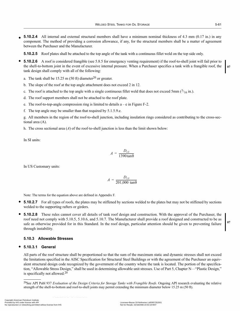
WELDED STEEL TANKS FOR OIL STORAGE 5-61
•
•07
•
•07
•
Copyright AmericaProvided by IHS uNo reproduction o
5.10.2.4 All internal and external structural members shall have a minimum nominal thickness of 4.3 mm (0.17 in.) in anycomponent. The method of providing a corrosion allowance, if any, for the structural members shall be a matter of agreementbetween the Purchaser and the Manufacturer.
5.10.2.5 Roof plates shall be attached to the top angle of the tank with a continuous fillet weld on the top side only.
5.10.2.6 A roof is considered frangible (see 5.8.5 for emergency venting requirement) if the roof-to-shell joint will fail prior tothe shell-to-bottom joint in the event of excessive internal pressure. When a Purchaser specifies a tank with a frangible roof, thetank design shall comply with all of the following:
a. The tank shall be 15.25 m (50 ft) diameter20 or greater.
b. The slope of the roof at the top angle attachment does not exceed 2 in 12.
c. The roof is attached to the top angle with a single continuous fillet weld that does not exceed 5mm (3/16 in.).
d. The roof support members shall not be attached to the roof plate.
e. The roof-to-top-angle compression ring is limited to details a – e in Figure F-2.
f. The top angle may be smaller than that required by 5.1.5.9.e.
g. All members in the region of the roof-to-shell junction, including insulation rings considered as contributing to the cross-sec-tional area (A).
h. The cross sectional area (A) of the roof-to-shell junction is less than the limit shown below:
In SI units:
In US Customary units:
Note: The terms for the equation above are defined in Appendix F.
5.10.2.7 For all types of roofs, the plates may be stiffened by sections welded to the plates but may not be stiffened by sectionswelded to the supporting rafters or girders.
5.10.2.8 These rules cannot cover all details of tank roof design and construction. With the approval of the Purchaser, theroof need not comply with 5.10.5, 5.10.6, and 5.10.7. The Manufacturer shall provide a roof designed and constructed to be assafe as otherwise provided for in this Standard. In the roof design, particular attention should be given to preventing failurethrough instability.
5.10.3 Allowable Stresses
5.10.3.1 General
All parts of the roof structure shall be proportioned so that the sum of the maximum static and dynamic stresses shall not exceedthe limitations specified in the AISC Specification for Structural Steel Buildings or with the agreement of the Purchaser an equiv-alent structural design code recognized by the government of the country where the tank is located. The portion of the specifica-tion, “Allowable Stress Design,” shall be used in determining allowable unit stresses. Use of Part 5, Chapter N—“Plastic Design,”is specifically not allowed.20
20See API Publ 937 Evaluation of the Design Criteria for Storage Tanks with Frangible Roofs. Ongoing API research evaluating the relativestrength of the shell-to-bottom and roof-to-shell joints may permit extending the minimum diameter below 15.25 m (50 ft).
ADLS
1390 θtan-----------------------=
ADLS
201,000 θtan--------------------------------=
n Petroleum Institute nder license with API Licensee=Bazan Oil Refineries Ltd/5957352001
Not for Resale, 02/18/2008 23:53:18 MSTr networking permitted without license from IHS
--``,,,,,,`,,`,`,`,``,,````,,``-`-`,,`,,`,`,,`---

5-62 API STANDARD 650
•
Copyright AmProvided by No reproduc
5.10.3.2 Minimum Thicknesses
The minimum thickness of any structural member, including any corrosion allowance on the exposed side or sides, shall not beless than 6 mm (0.250 in.) for columns, knee braces and beams or stiffeners which by design normally resist axial compressiveforces or 4 mm (0.17 in.) for any other structural member.
5.10.3.3 Maximum Slenderness Ratios
For columns, the value L/rc shall not exceed 180. For other compression members, the value L/r shall not exceed 200. For allother members, except tie rods whose design is based on tensile force, the value L/r shall not exceed 300.
where
L = unbraced length, mm (in.),rc = least radius of gyration of column, mm (in.),
r = governing radius of gyration, mm (in.).
5.10.3.4 Columns
When the Purchaser does not specify lateral loads that will be imposed on the roof-supporting columns and the column member isnot considered to be a slender element section by the AISC Specification, the following formula for allowable compression may beused in lieu of the formulas in the AISC Specification when l/r exceeds 120 and the yield stress of column (Fy) is less than or equalto 250 MPa (36,000 lbf/in.2). When the Purchaser specifies lateral loads that will be imposed on the roof-supporting columns, thecolumns must be proportioned to meet the requirements for combined axial compression and bending as specified in 5.10.3.When l/r is less than or equal to Cc:
where
When l/r exceeds Cc:
where
Fa = allowable compression stress, MPa (lbf/in.2),
Fy = yield stress of material, MPa (lbf/in.2),
E = modulus of elasticity, MPa (lbf/in.2),
l = unbraced length of the column, mm (in.),
r = least radius of gyration of column, mm (in.).
Fa
1 l r⁄( )2
2Cc2--------------– Fy
53--- 3 l r⁄( )
8Cc--------------- l r⁄( )3
8Cc3--------------–+
---------------------------------------------
1.6 l200r-----------–
---------------------------------------------------=
Cc2π2E
Fy------------=
Fa
12π2E23 l r⁄( )2--------------------
1.6 l200r-----------–
------------------------------=
erican Petroleum Institute IHS under license with API Licensee=Bazan Oil Refineries Ltd/5957352001
Not for Resale, 02/18/2008 23:53:18 MSTtion or networking permitted without license from IHS
--``,,,,,,`,,`,`,`,``,,````,,``-`-`,,`,,`,`,,`---

WELDED STEEL TANKS FOR OIL STORAGE 5-63
• 07
•
•
07
•
Copyright AmericaProvided by IHS uNo reproduction o
5.10.4 Supported Cone Roofs
5.10.4.1 The slope of the roof shall be 1:16 or greater if specified by the Purchaser. If the rafters are set directly on chord gird-ers, producing slightly varying rafter slopes, the slope of the flattest rafter shall conform to the specified or ordered roof slope.
5.10.4.2 Main supporting members, including those supporting the rafters, may be rolled or fabricated sections or trusses.Although these members may be in contact with the roof plates, the compression flange of a member or the top chord of a trussshall be considered as receiving no lateral support from the roof plates and shall be laterally braced, if necessary, by other accept-able methods. The allowable stresses in these members shall be governed by 5.10.3.
5.10.4.3 Structural members serving as rafters may be rolled or fabricated sections but in all cases shall conform to the rules of5.10.2, 5.10.3, and 5.10.4. Rafters shall be designed for the dead load of the rafters and roof plates with the compression flange ofthe rafter considered as receiving no lateral support from the roof plates and shall be laterally braced if necessary (see 5.10.4.2).When considering additional dead loads or live loads, the rafters in direct contact with the roof plates applying the loading to therafters may be considered as receiving adequate lateral support from the friction between the roof plates and the compressionflanges of the rafters, with the following exceptions:
a. Trusses and open-web joints used as rafters.b. Rafters with a nominal depth greater than 375 mm (15 in.).c. Rafters with a slope greater than 1:6.
5.10.4.4 Rafters shall be spaced so that in the outer ring, their centers are not more than 0.6π m (2π ft [6.28 ft]) apart measuredalong the circumference of the tank. Spacing on inner rings shall not be greater than 1.7 m (5.5 ft).
5.10.4.5 Roof columns shall be made from either pipe or structural shapes as selected on the Data Sheet, Line 11. Pipe columnsshall either be sealed or have openings on both the top and bottom of the column.
5.10.4.6 Rafter clips for the outer row of rafters shall be welded to the tank shell.
5.10.4.7 Roof support columns shall be provided at their bases with details that provide for the following:
a. Load Distribution: Column loads shall be distributed over a bearing area based on the specified soil bearing capacity or foun-dation design. Where an unstiffened horizontal plate is designed to distribute the load, it shall be a minimum of 12 mm (1/2 in.)thick. Alternatively, the column load may be distributed by an assembly of structural beams. The plate or members shall bedesigned to distribute the load without exceeding allowable stresses prescribed in 5.10.3.1.
b. Corrosion and Abrasion Protection: At each column a wear plate with a minimum 6 mm (1/4 in.) thickness shall be welded tothe tank bottom with a 6 mm (1/4 in.) minimum fillet weld. A single adequate thickness plate may be designed for the dual func-tions of load distribution and corrosion/abrasion protection.
c. Vertical Movement: The design shall allow the columns to move vertically relative to the tank bottom without restraint in theevent of tank overpressure or bottom settlement.
d. Lateral Movement: The columns shall be effectively guided at their bases to prevent lateral movement. The guides shallremain effective in the event of vertical movement of columns relative to tank bottom of up to 75 mm (3 in.). The guides shall belocated such that they are not welded directly to the tank bottom plates.
5.10.4.8 Three acceptable arrangements to provide the functions required by 5.10.4.7 are illustrated in Figure 5-26.
5.10.4.9 For Appendix F tanks, when supporting members are attached to the roof plate, consideration shall be given to thedesign of the supporting members and their attachment details when considering internal pressure.
5.10.5 Self-Supporting Cone Roofs
Note: Self-supporting roofs whose roof plates are stiffened by sections welded to the plates need not conform to the minimum thickness require-ments, but the thickness of the roof plates shall not be less than 5 mm (3/16 in.) when so designed by the Manufacturer, subject to the approval ofthe Purchaser.
5.10.5.1 Self-supporting cone roofs shall conform to the following requirements:
θ ≤ 37 degrees (slope = 9:12)θ ≥ 9.5 degrees (slope = 2:12)
--``,,,,,,`,,`,`,`,``,,````,,``-`-`,,`,,`,`,,`---
n Petroleum Institute nder license with API Licensee=Bazan Oil Refineries Ltd/5957352001
Not for Resale, 02/18/2008 23:53:18 MSTr networking permitted without license from IHS

5-64 API STANDARD 650
07
Copyright AmProvided by No reproduc
--``,,,,,,`,,`,`,`,``,,````,,``-`-`,,`,,`,`,,`---
Figure 5-26—Some Acceptable Column Base Details
No weld
Structural Column
Guide
Plate acting as Sealed WearPlate that is also thick enoughto distribute load
Bottom plate
A
No weld
Column
Guide
Sealed wear plate
Plate that is thick enoughto distribute load
Bottom plate
C
No weld
Column
Guide
Sealed wear plate
Bottom plate
Assembly of structural beams
B
Pipe Column
erican Petroleum Institute IHS under license with API Licensee=Bazan Oil Refineries Ltd/5957352001
Not for Resale, 02/18/2008 23:53:18 MSTtion or networking permitted without license from IHS

WELDED STEEL TANKS FOR OIL STORAGE 5-65
Copyright AmericaProvided by IHS uNo reproduction o
In SI units:
Minimum thickness =
Maximum thickness = 12.5 mm, exclusive of corrosion allowance
where
D = nominal diameter of the tank shell (m),
T = greater of load combinations (e)(1) and (e)(2) of Appendix R (kPa),
θ = angle of cone elements to the horizontal (deg).
In US Customary units:
Minimum thickness =
Maximum thickness = 1/2 in., exclusive of corrosion allowance
where
D = nominal diameter of the tank shell (ft),
T = greater of load combinations (e)(1) and (e)(2) of Appendix R (lbf/ft2),
θ = angle of cone elements to the horizontal (deg).
5.10.5.2 The participating area at the roof-to-shell junction shall be determined using Figure F-2 and shall equal or exceed thefollowing:
In SI units:
where
D = nominal diameter of the tank shell (m),
T = greater of load combinations (e)(1) and (e)(2) of Appendix R (kPa),
θ = angle of cone elements to the horizontal (deg).
The area calculated from this expression is based on the nominal material thickness less any corrosion allowance.
In US Customary units:
where
D = nominal diameter of the tank shell (ft),
T = greater of load combinations (e)(1) and (e)(2) of Appendix R (lbf/ft2),
θ = angle of cone elements to the horizontal (deg).
The area calculated from this expression is based on the nominal material thickness less any corrosion allowance.
D4.8 θsin------------------ T
2.2------- 5 mm≥
D400 θsin-------------------- T
45------ 3 16⁄ in.≥
D2
0.432 θsin------------------------ T
2.2-------⎝ ⎠⎛ ⎞
D2
3000 θsin----------------------- T
45------⎝ ⎠⎛ ⎞
--``,,,,,,`,,`,`,`,``,,````,,``-`-`,,`,,`,`,,`---
n Petroleum Institute nder license with API Licensee=Bazan Oil Refineries Ltd/5957352001
Not for Resale, 02/18/2008 23:53:18 MSTr networking permitted without license from IHS

5-66 API STANDARD 650
•
Copyright AmProvided by No reproduc
5.10.6 Self-Supporting Dome and Umbrella Roofs
Note: Self-supporting roofs whose roof plates are stiffened by sections welded to the plates need not conform to the minimum thickness require-ments, but the thickness of the roof plates shall not be less than 5 mm (3/16 in.) when so designed by the Manufacturer, subject to the approval ofthe Purchaser.
5.10.6.1 Self-supporting dome and umbrella roofs shall conform to the following requirements:
Minimum radius = 0.8D (unless otherwise specified by the Purchaser)
Maximum radius = 1.2D
In SI units:
Minimum thickness =
Maximum thickness = 12.5 mm, exclusive of corrosion allowance
where
D = nominal diameter of the tank shell (m),T = greater of load combinations (e)(1) and (e)(2) of Appendix R (kPa),r = roof radius (m).
In US Customary units:
Minimum thickness =
Maximum thickness = 1/2 in., exclusive of corrosion allowance
where D = nominal diameter of the tank shell (ft),T = greater of load combinations (e)(1) and (e)(2) of Appendix R (lbf/ft2),r = roof radius (ft).
5.10.6.2 The participating area, in mm2, at the roof-to-shell junction shall be determined using Figure F-2, and shall equal orexceed the following:
The area calculated from the expression above is based on the nominal material thickness less any corrosion allowance.
In US Customary units: The participating area, in in.2, at the roof-to-shell junction shall be determined using Figure F-2 and shall equal or exceed thefollowing:
The area calculated from the expression above is based on the nominal material thickness less any corrosion allowance.
5.10.7 Top-Angle Attachment for Self-Supporting Roofs
Information and certain restrictions on types of top-angle joints are provided in Item c of 5.1.5.9. Details of welding are providedin 7.2.
rr
2.4------- T
2.2------- C.A.+ 5 mm≥
rr
200--------- T
45------ C.A.+ 3 16⁄ in.≥
Drr
0.216------------- T
2.2-------⎝ ⎠⎛ ⎞
Drr
1500------------ T
45------⎝ ⎠⎛ ⎞
--``,,,,,,`,,`,`,`,``,,````,,``-`-`,,`,,`,`,,`---
erican Petroleum Institute IHS under license with API Licensee=Bazan Oil Refineries Ltd/5957352001
Not for Resale, 02/18/2008 23:53:18 MSTtion or networking permitted without license from IHS

WELDED STEEL TANKS FOR OIL STORAGE 5-67
07
Copyright AmericaProvided by IHS uNo reproduction o
--``,,,,,,`,,`,`,`,``,,````,,``-`-`,,`,,`,`,,`---
5.11 WIND LOAD ON TANKS (OVERTURNING STABILITY)
5.11.1 Wind Pressure
Overturning stability shall be calculated using the wind pressures given in 5.2.1(j).
5.11.2 Unanchored Tanks
Unanchored tanks shall satisfy both of the following uplift criteria:
1. 0.6Mw + MPi < MDL /1.5
2. Mw + 0.4MPi < (MDL + MF)/2
where
MPi = moment about the shell-to-bottom joint from design internal pressure,
Mw = overturning moment about the shell-to-bottom joint from horizontal plus vertical wind pressure,
MDL = moment about the shell-to-bottom joint from the weight of the shell and roof supported by the shell,
MF = moment about the shell-to-bottom joint from liquid where weight of liquid is wa defined in E.2.2 using a specific
gravity of 0.7 and a height of one half the design liquid height H, so in SI units, and in US Cus-
tomary units (see Figure 5-27).
Figure 5-27—Overturning Check for Unanchored Tanks
wa 59tb FbyH=
wa 4.67tb FbyH=
Wind uplift load
Internal pressure load
D/2
H
Dead load (DL)
Liquid hold down weight (wa)
Moments aboutshell to bottom Joint
Wind load on shell
H/2 for uniformpressure on shell
n Petroleum Institute nder license with API Licensee=Bazan Oil Refineries Ltd/5957352001
Not for Resale, 02/18/2008 23:53:18 MSTr networking permitted without license from IHS

5-68 API STANDARD 650
07
•
•
Copyright AmProvided by No reproduc
--``,,,,,,`,,`,`,`,``,,````,,``-`-`,,`,,`,`,,`---
5.11.3 Anchored Tanks
When anchors are required, the design tension load per anchor shall be calculated as follows:
tb = 4Mw/dN – W/N
where
tb = design tension load per anchor (N) (lbf),
d = diameter of the anchor circle (m) (ft),
N = number of anchors,
W = weight of the shell plus roof supported by the shell less 0.4 times the uplift from internal pressure.
5.11.4 Sliding Friction
Unless otherwise required, tanks that may be subject to sliding due to wind shall use a maximum allowable sliding friction of 0.40multiplied by the force against the tank bottom.
5.12 TANK ANCHORAGE
5.12.1 When a tank is required to be anchored per 5.11, Appendix E, Appendix F, or when a tank is anchored for any other rea-son, the following minimum requirements shall be met.
5.12.2 Anchorage shall be provided to resist each of the uplift load cases listed in Table 5-21. The load per anchor shall be:
tb = U/N
where
tb = load per anchor,
U = net uplift load per Table 5-21,
N = number of anchors (a minimum of 4 is required),
5.12.3 The spacing between anchors shall not exceed 3 m (10 ft).
5.12.4 Allowable stresses for anchor bolts shall be in accordance with Table 5-21 for each load case. The allowable stress shallapply to the net (root) area of the anchor bolt.
5.12.5 The Purchaser shall specify any corrosion allowance that is to be added to the anchor dimensions. Unless otherwisespecified, corrosion allowance for anchor bolts shall be applied to the nominal diameter. The minimum anchor bolt diameter is1 in. plus any specified corrosion allowance.
5.12.6 Attachment of the anchor bolts to the shell shall be through stiffened chair-type assemblies or anchor rings of sufficientsize and height. An acceptable procedure for anchor chair design is given in AISI E-1, Volume II, Part VII “Anchor Bolt Chairs.”When acceptable to the Purchaser, anchor straps may be used if the shell attachment is via chair-type assemblies or anchor ringsof sufficient size and height.
5.12.7 Other evaluations of anchor attachments to the shell may be made to ensure that localized stresses in the shell will beadequately handled. An acceptable evaluation technique is given in ASME Section VIII Division 2, Appendix 4, using the allow-able stresses given in this section for Sm. The method of attachment shall take into consideration the effect of deflection and rota-tion of the shell.
5.12.8 Allowable stresses for anchorage parts shall be in accordance with 5.10.3. A 33% increase of the allowable stress maybe used for wind or seismic loading conditions.
5.12.9 The maximum allowable local stress in the shell at the anchor attachment shall be in accordance with Table 5-21 unlessan alternate evaluation is made in accordance with 5.12.7.
erican Petroleum Institute IHS under license with API Licensee=Bazan Oil Refineries Ltd/5957352001
Not for Resale, 02/18/2008 23:53:18 MSTtion or networking permitted without license from IHS

WELDED STEEL TANKS FOR OIL STORAGE 5-69
Copyright AmericaProvided by IHS uNo reproduction o
--``,,,,,,`,,`,`,`,``,,````,,``-`-`,,`,,`,`,,`---
Table 5-21a—Uplift Loads (SI Units)
Uplift Load Case Net Uplift Formula, U (N)Allowable Anchor Bolt
Stress (MPa)
Allowable Shell Stress at Anchor Attachment
(MPa)Design Pressure [(P – 0.08th) × D2 × 0.785] – W1 105 140Test Pressure [(Pt – 0.08th) × D2 × 0.785] – W1 140 170Failure Pressurea [(1.5 × Pf – 0.08th) × D2 × 0.785] – W3 Fy FtyWind Load [4 × Mw/D] – W2 0.8 × Fy 170Seismic Load [4 × Ms/D] – W2 0.8 × Fy 170Design Pressure + Wind [(P – 0.08th) × D2 × 0.785] + [4 Mw/D] – W1 140 170Design Pressure + Seismic [(P – 0.08th) × D2 × 0.785] + [4 Ms/D] – W1 0.8 × Fy 170
Table 5-21b—Uplift Loads (US Customary Units)
Uplift Load Case Net Uplift Formula, U (lbf)Allowable Anchor Bolt
Stress (lbf/in.2)
Allowable Anchor Bolt Stress at Anchor
Attachment (lbf/in.2)Design Pressure [(P – 8th) × D2 × 4.08] – W1 15,000 20,000Test Pressure [(Pt – 8th) × D2 × 4.08] – W1 20,000 25,000Failure Pressurea [(1.5 × Pf – 8th) × D2 × 4.08] – W3 Fy FtyWind Load [4 × Mw/D] – W2 0.8 × Fy 25,000Seismic Load [4 × Ms/D] – W2 0.8 × Fy 25,000Design Pressure + Wind [(P – 8th) × D2 × 4.08] + [4 Mw/D] – W1 20,000 25,000Design Pressure + Seismic [(P – 8th) × D2 × 4.08] + [4 Ms/D] – W1 0.8 × Fy 25,000
whereD = tank diameter in (m)
Fty = minimum yield strength of the bottom shell course(MPa)
P = design pressure in (kPa) (see Appendix F)Pt = test pressure in (kPa) (see Appendix F)
Pf = failure pressure in (kPa) (see Appendix F)
th = roof plate thickness (mm)
Mw = wind moment in (N-m) (see 5.11)
Ms = seismic moment in (N-m) (see Appendix E)
W1 = dead load of shell minus any corrosion allowance andany dead load other than roof plate acting on the shellminus any corrosion allowance (N)
W2 = dead load of shell minus any corrosion allowanceand any dead load including roof plate acting on theshell minus any corrosion allowance (N)
W3 = dead load of the shell using as-built thicknesses andany dead load other than roof plate acting on the shellusing as-built thicknesses (N)
aFailure pressure applies to tanks falling under F.1.3 only. The failurepressure shall be calculated using as-built thicknesses.
whereD = tank diameter in ft
Fty = minimum yield strength of the bottom shell course(psi)
P = design pressure in inches of water column (seeAppendix F)
Pt = test pressure in inches of water column (seeAppendix F)
Pf = failure pressure in inches of water column (seeAppendix F)
th = roof plate thickness in inchesMw = wind moment in ft-lbs (see 5.11)
Ms = seismic moment in ft-lbs (see Appendix E)W1 = dead load of shell minus any corrosion allowance and
any dead load other than roof plate acting on the shellminus any corrosion allowance (lbf)
W2 = dead load of shell minus any corrosion allowanceand any dead load including roof plate acting on theshell minus any corrosion allowance (lbf)
W3 = dead load of the shell using as-built thicknesses andany dead load other than roof plate acting on the shellusing as-built thicknesses (lbf)
aFailure pressure applies to tanks falling under F.1.3 only. The failurepressure shall be calculated using as-built thicknesses.
n Petroleum Institute nder license with API Licensee=Bazan Oil Refineries Ltd/5957352001
Not for Resale, 02/18/2008 23:53:18 MSTr networking permitted without license from IHS
5-70 API STANDARD 650
•
Copyright AmProvided by No reproduc
5.12.10 When specified by the Purchaser, the anchors shall be designed to allow for thermal expansion of the tank resultingfrom a temperature greater than 93°C (200°F).
5.12.11 Any anchor bolts shall be uniformly tightened to a snug fit, and any anchor straps shall be welded while the tank isfilled with test water but before any pressure is applied on top of the water. Measures such as peening the threads or adding lock-ing nuts, shall be taken to prevent the nuts from backing off the threads.
5.12.12 The embedment strength of the anchor in the foundation shall be sufficient to develop the specified minimum yieldstrength of the anchor. Hooked anchors or end plates may be used to resist pullout.
5.12.13 The foundation shall provide adequate counterbalancing weight to resist the design uplift loads in accordance with thefollowing:
5.12.13.1 The counterbalancing weight, such as a concrete ringwall, shall be designed so that the resistance to net uplift is inaccordance with Table 5-21. When considering uplift due to a wind or seismic moment, an evaluation shall be made to insureoverturning stability of the foundation and to insure soil-bearing pressures are within allowable stress levels as determined usingthe recommendations of Appendix B.
5.12.13.2 When a footing is included in the ringwall design, the effective weight of the soil above the footing may be includedin the counterbalancing weight.
--``,,,,,,`,,`,`,`,``,,````,,``-`-`,,`,,`,`,,`---
erican Petroleum Institute IHS under license with API Licensee=Bazan Oil Refineries Ltd/5957352001
Not for Resale, 02/18/2008 23:53:18 MSTtion or networking permitted without license from IHS

•
07
•
•
07
•
Copyright AmericaProvided by IHS uNo reproduction o
--``,,,,,,`
SECTION 6—FABRICATION
6.1 GENERAL
6.1.1 Workmanship
6.1.1.1 All work of fabricating API Std 650 tanks shall be done in accordance with this Standard and with the permissible alter-natives specified in the Purchaser’s inquiry or order. The workmanship and finish shall be first class in every respect and subjectto the closest inspection by the Manufacturer’s inspector even if the Purchaser has waived any part of the inspection.
6.1.1.2 When material requires straightening, the work shall be done by pressing or another noninjurious method prior to anylayout or shaping. Heating or hammering is not permissible unless the material is maintained at forging temperature duringstraightening.
6.1.1.3 Materials used to aid in the fabrication of tanks shall not have a detrimental effect on the structural integrity of the tank.Lubricants, crayons, adhesives, and anti-weld spatter compounds shall not contain materials that will be detrimental to the tank,e.g., sulfur and chloride compounds for stainless steel materials. Attachments that will be welded to the pressure boundary shallnot have a zinc or cadmium coating in the weld area within 12 mm (0.5 in.) of the weld.
6.1.2 Finish of Plate Edges
The edges of plates may be sheared, machined, chipped, or machine gas cut. Shearing shall be limited to plates less than or equalto 10 mm (3/8 in.) thick used for butt-welded joints and to plates less than or equal to 16 mm (5/8 in.) thick used for lap-weldedjoints.
Note: With the Purchaser’s approval, the shearing limitation on plates used for butt-welded joints may be increased to a thickness less than orequal to 16 mm (5/8 in.).
When edges of plates are gas cut, the resulting surfaces shall be uniform and smooth and shall be freed from scale and slag accu-mulations before welding. After cut or sheared edges are wire brushed, the fine film of rust adhering to the edges need not beremoved before welding. Circumferential edges of roof and bottom plates may be manually gas cut.
6.1.3 Shaping of Shell Plates
Figure 6-1 provides criteria for shaping of plates to the curvature of the tank prior to installation in the tank. Shaping of plates con-currently with installation in the tank shell is permitted if the tank diameter exceeds the limit in Figure 6-1 or if the Manufacturer’salternate procedure for any diameter has been accepted by the Purchaser.
6.1.4 Marking
All special plates that are cut to shape before shipment as well as roof-supporting structural members shall be marked as shownon the Manufacturer’s drawings.
6.1.5 Shipping
Plates and tank material shall be loaded in a manner that ensures delivery without damage. Bolts, nuts, nipples, and other smallparts shall be boxed or put in kegs or bags for shipment. All flange faces and other machined surfaces shall be protected againstcorrosion and from physical damage.
6.2 SHOP INSPECTION
6.2.1 The Purchaser’s inspector shall be permitted free entry to all parts of the Manufacturer’s plant that are concerned with thecontract whenever any work under the contract is being performed. The Manufacturer shall afford the Purchaser’s inspector allreasonable facilities to assure the inspector that the material is being furnished in accordance with this Standard. Also, the Manu-facturer shall furnish samples or specimens of materials for the purpose of qualifying welders in accordance with 9.3.Unless otherwise specified, inspection shall be made at the place of manufacture prior to shipment. The Manufacturer shall givethe Purchaser ample notice of when the mill will roll the plates and when fabrication will begin so that the Purchaser’s inspectormay be present when required. The usual mill test of plates shall be deemed sufficient to prove the quality of the steel furnished
6-1
n Petroleum Institute nder license with API Licensee=Bazan Oil Refineries Ltd/5957352001
Not for Resale, 02/18/2008 23:53:18 MSTr networking permitted without license from IHS
,,`,`,`,``,,````,,``-`-`,,`,,`,`,,`---

6-2 API STANDARD 650
•
07
07
Copyright AmProvided by No reproduc
--``,,,,,,`,,`,`,`,``,,````,,``-`-`,,`,,`,`,,`---
(except as noted in 6.2.2). Mill test reports or certificates of compliance, as provided for in the material specification, shall be fur-nished to the Purchaser only when the option is specified in the original contract that they be provided.
6.2.2 Mill and shop inspection shall not release the Manufacturer from responsibility for replacing any defective material andfor repairing any defective workmanship that may be discovered in the field.
6.2.3 Any material or workmanship that in any way fails to meet the requirements of this Standard may be rejected by the Pur-chaser’s inspector, and the material involved shall not be used under the contract. Material that shows injurious defects subse-quent to its acceptance at the mill, subsequent to its acceptance at the Manufacturer’s works, or during erection and testing of thetank will be rejected. The Manufacturer will be notified of this in writing and will be required to furnish new material promptlyand make the necessary replacements or suitable repairs.
6.2.4 a. The Manufacturer shall visually inspect all edges of shell and roof plates before installing the plates in the tank orbefore inserting a nozzle into the plate to determine if laminations are present. If a lamination is visually detected, the Manufac-turer shall ultrasonically test the area to determine the extent of the laminations and shall reject the plate or make repairs in accor-dance with 6.2.4b.
b. For laminations found not exceeding 75 mm (3 in.) in length or 25 mm (1 in.) in depth, repairs may be made by edge gougingand rewelding to seal the lamination. The Manufacturer shall submit the edge repair procedure for Purchaser acceptance prior tothe start of fabrication. For laminations exceeding these limits, the Manufacturer shall either reject the plate or repair the plate byentirely removing the lamination. Before making such repairs the Manufacturer shall document the extent of the lamination andsubmit a case-specific repair procedure for Purchaser approval.
Figure 6-1—Shaping of Plates
mm
16
13
10
5
ALL ft.
m 12 18Tank Diameter
She
ll P
late
Thi
ckne
ss
Shaping requiredprior to installation
Shaping not required
36 ALL
in.
5/8
1/2
3/8
3/16
ALL40 60 120 ALL
Note: Any combination of diameter and thickness falling on or above the solid line requires shaping prior to installation.
•
erican Petroleum Institute IHS under license with API Licensee=Bazan Oil Refineries Ltd/5957352001
Not for Resale, 02/18/2008 23:53:18 MSTtion or networking permitted without license from IHS

•
• 07
•
Copyright AmericaProvided by IHS uNo reproduction o
SECTION 7—ERECTION
7.1 GENERAL
7.1.1 Required foundation and grade work shall be supplied by the Purchaser, unless otherwise specified in the Contract. TheManufacturer shall check level tolerances and contour before starting work, and shall notify the Purchaser of any deficiency dis-covered that might affect the quality of the finished work. Deficiencies noted shall be rectified by the Purchaser unless otherwiseagreed by the Manufacturer.
7.1.2 After the Purchaser has turned the tank foundation over to the Manufacturer, the Manufacturer shall maintain the gradeunder the tank in true profile and free of foreign materials such as clay, coal, cinders, metal scraps, or animal or vegetable matterof any sort. The Manufacturer shall repair any damage to either the foundation or grade surface caused by the Manufacturer’soperations.
7.1.3 Coating or foreign material shall not be used between surfaces in contact in the construction of the tank, except as permit-ted by 7.2.1.9.
7.1.4 Coating or other protection for structural work inside and outside of the tank shall be as specified in the contract and shallbe applied by competent workers.
7.1.5 All temporary attachments welded to the exterior of the tank shall be removed and any noticeable projections of weldmetal shall be ground smooth with the surface of the plate. In the event of inadvertent tearing of the plate when attachments areremoved, the damaged area shall be repaired by welding and subsequent grinding of the surface to a smooth condition.
7.1.6 All temporary attachments welded to the interior of the tank, including the shell, roof, tank bottom, roof columns andother internal structures shall be removed and any noticeable projections of weld metal shall be ground smooth. In the event ofinadvertent tearing of the plate when attachments are removed, the damaged area shall be repaired by welding and subsequentgrinding of the surface to a smooth condition. This work must be completed before the application of internal coatings, the airraising of a fixed roof, the initial floating of a floating roof, and any other circumstance whereby projections may cause damage.
7.2 DETAILS OF WELDING
7.2.1 General
7.2.1.1 Tanks and their structural attachments shall be welded by the shielded metal-arc, gas metal-arc, gas tungsten-arc, oxy-fuel, flux-cored arc, submerged-arc, electroslag, or electrogas process using suitable equipment. Use of the oxyfuel, electroslag,or electrogas process shall be by agreement between the Manufacturer and the Purchaser. Use of the oxyfuel process is not per-mitted when impact testing of the material is required. All tank welding shall be performed in accordance with the requirementsof Section 9 of this Standard and welding procedure specifications as described in Section IX of the ASME Code. Welding shallbe performed in a manner that ensures complete fusion with the base metal.
7.2.1.2 No welding of any kind shall be performed when the surfaces to be welded are wet from rain, snow, or ice; when rain orsnow is falling on such surfaces; or during periods of high winds unless the welder and the work are properly shielded. Also, pre-heat shall be applied when metal temperature is below the temperature required by Table 7-1. In that case the base metal shall beheated to at least the temperature indicated in Table 7-1 within 75 mm (3 in.) of the place where welding is to be started and main-tained 75 mm (3 in.) ahead of the arc.
Table 7-1—Minimum Preheat Temperatures
Material Group per Table 2-3
Thickness (t) of Thicker Plate mm (in.)
Minimum Preheat Temperature
Groups I, II, III & IIIA
t ≤ 32 (t ≤ 1.25) 0ºC (32ºF)
32 < t ≤ 38 (1.25 < t ≤ 1.50) 10ºC (50ºF)
t > 38 (t > 1.50) 93ºC (200ºF)
Groups IV, IVA, V & VI
t ≤ 32 (t ≤ 1.25) 10ºC (50ºF)
32 < t ≤ 38 (1.25 < t ≤ 1.50) 40ºC (100ºF)
t > 38 (t > 1.50) 93ºC (200°F)
7-1
n Petroleum Institute nder license with API Licensee=Bazan Oil Refineries Ltd/5957352001
Not for Resale, 02/18/2008 23:53:18 MSTr networking permitted without license from IHS
--``,,,,,,`,,`,`,`,``,,````,,``-`-`,,`,,`,`,,`---

7-2 API STANDARD 650
07
•
Copyright AmProvided by No reproduc
7.2.1.3 Each layer of weld metal or multilayer welding shall be cleaned of slag and other deposits before the next layer isapplied.
7.2.1.4 The edges of all welds shall merge smoothly with the surface of the plate without a sharp angle.
7.2.1.5 All welding shall be free from coarse ripples, grooves, overlaps, abrupt ridges, and valleys that interfere with interpreta-tion of NDE results.
7.2.1.6 During the welding operation, plates shall be held in close contact at all lap joints.
7.2.1.7 The method proposed by the Manufacturer for holding the plates in position for welding shall be submitted to the Pur-chaser’s inspector for approval if approval has not already been given in writing by the Purchaser.
7.2.1.8 Tack welds used during the assembly of vertical joints of tank shells shall be removed and shall not remain in the fin-ished joints when the joints are welded manually. When such joints are welded by the submerged-arc process, the tack welds shallbe thoroughly cleaned of all welding slag but need not be removed if they are sound and are thoroughly fused into the subse-quently applied weld beads.Whether tack welds are removed or left in place, they shall be made using a fillet-weld or butt-weld procedure qualified in accor-dance with Section IX of the ASME Code. Tack welds to be left in place shall be made by welders qualified in accordance withSection IX of the ASME Code and shall be visually examined for defects, which shall be removed if found (see 8.5 for criteria forvisual examination).
7.2.1.9 If protective coatings are to be used on surfaces to be welded, the coatings shall be included in welding-procedure qual-ification tests for the brand formulation and maximum thickness of coating to be applied.
7.2.1.10 Low-hydrogen electrodes shall be used for all manual metal-arc welds in annular rings and shell courses, including theattachment of the first shell course to bottom or annular plates, as follows:
a. Where the plates are thicker than 12.5 mm (1/2 in.) (based on the thickness of the thicker member being joined) and made ofmaterial from Groups I–III.b. For all thicknesses when the plates are made of material from Groups IV, IVA, V and VI.
7.2.1.11 Non-structural small attachments such as insulation clips, studs and pins but not insulation support rings or bars maybe welded by the arc stud, capacitor discharge or shielded metal arc process to the exterior of the shell including reinforcing platesor PWHT assemblies and roof either before or after hydrostatic testing is performed, but before the tank will be filled with prod-uct provided:
a. The attachment locations meet the spacing requirements of 5.8.1.2a.
b. The arc stud welding process is limited to 10 mm (3/8 in.) maximum diameter studs or equivalent cross-section.
c. The maximum shielded metal arc electrode is limited to 3 mm (1/8 in.) diameter and shall be a low-hydrogen type.
d. The attachment welds, except for those made by the capacitor discharge method, shall be inspected per 7.2.3.5. The attachmentwelds made by the capacitor discharge method shall be visually examined for all types and groups of shell materials.
e. All stud welding and capacitor discharge procedures have been qualified in accordance with ASME Section IX. Capacitor dis-charge procedures do not require procedure qualification provided the power output is 125 watt-sec or less.
The shielded metal arc weld procedures shall meet the requirements of Section 9 for qualification for use.
7.2.2 Bottoms
7.2.2.1 After the bottom plates are laid out and tacked, they shall be joined by welding the joints in a sequence that the Manu-facturer has found to result in the least distortion from shrinkage and thus to provide as nearly as possible a plane surface.
7.2.2.2 The welding of the shell to the bottom shall be practically completed before the welding of bottom joints that may havebeen left open to compensate for shrinkage of any welds previously made is completed.
7.2.2.3 Shell plates may be aligned by metal clips attached to the bottom plates, and the shell may be tack welded to the bottombefore continuous welding is started between the bottom edge of the shell plate and the bottom plates.
--``,,,,,,`,,`,`,`,``,,````,,``-`-`,,`,,`,`,,`---
erican Petroleum Institute IHS under license with API Licensee=Bazan Oil Refineries Ltd/5957352001
Not for Resale, 02/18/2008 23:53:18 MSTtion or networking permitted without license from IHS

WELDED STEEL TANKS FOR OIL STORAGE 7-3
•
•
Copyright AmericaProvided by IHS uNo reproduction o
--``,,,,,,`,,`,`,`,``,,````,,``-`-`,,`,,`,`,,`---
7.2.3 Shells
7.2.3.1 Plates to be joined by butt welding shall be matched accurately and retained in position during the welding operation.Misalignment in completed vertical joints for plates greater than 16 mm (5/8 in.) thick shall not exceed 10% of the plate thick-ness or 3 mm (1/8 in.), whichever is less; misalignment for plates less than or equal to 16 mm (5/8 in.) thick shall not exceed1.5 mm (1/16 in.).
7.2.3.2 In completed horizontal butt joints, the upper plate shall not project beyond the face of the lower plate at any point bymore than 20% of the thickness of the upper plate, with a maximum projection of 3 mm (1/8 in.); however, for upper plates lessthan 8 mm (5/16 in.) thick, the maximum projection shall be limited to 1.5 mm (1/16 in.).
7.2.3.3 The reverse side of double-welded butt joints shall be thoroughly cleaned in a manner that will leave the exposed sur-face satisfactory for fusion of the weld metal to be added, prior to the application of the first bead to the second side. This cleaningmay be done by chipping; grinding; melting out; or where the back of the initial bead is smooth and free from crevices that mightentrap slag, another method that, upon field inspection, is acceptable to the Purchaser.
7.2.3.4 For circumferential and vertical joints in tank shell courses constructed of material more than 38 mm (11/2 in.) thick(based on the thickness of the thicker plate at the joint), multipass weld procedures are required, with no pass over 19 mm (3/4 in.)thick permitted.
7.2.3.5 The requirements of this section shall be followed when welding to Group IV, IVA, V, and VI materials. Permanent andtemporary attachments (see 7.2.1.10 for information on shell-to-bottom welds) shall be welded with low-hydrogen electrodes.Both permanent and temporary attachments shall be welded in accordance with a procedure that minimizes the potential forunderbead cracking. The welds of permanent attachments (not including shell-to-bottom welds) and areas where temporaryattachments are removed, shall be examined visually and by either the magnetic particle method or by the liquid penetrant method(see 8.2, 8.4, or 8.5 for the appropriate inspection criteria).
7.2.3.6 Completed welds of stress-relieved assemblies shall be examined by visual, as well as by magnetic particle or penetrantmethods, after stress relief, but before hydrostatic test.
7.2.3.7 Flush-type connections shall be inspected according to 5.7.8.11.
7.2.4 Shell-to-Bottom Welds
7.2.4.1 The initial weld pass inside the shell shall have all slag and non-metals removed from the surface of the weld and thenexamined for its entire circumference prior to welding the first weld pass outside the shell (temporary weld fit-up tacks excepted),both visually and by one of the following methods to be agreed to by Purchaser and the Manufacturer:
a. Magnetic particle.b. Applying a solvent liquid penetrant to the weld and then applying a developer to the gap between the shell and the bottom andexamining for leaks after a minimum dwell time of one hour.c. Applying a water-soluble liquid penetrant to either side of the joint and then applying a developer to the other side of the jointand examining for leaks after a minimum dwell time of one hour.d. Applying a high flash-point penetrating oil such as light diesel to the gap between the shell and the bottom, letting stand for atleast four hours, and examining the weld for evidence of wicking.
Note: Residual oil may remain on the surfaces yet to be welded even after the cleaning required below and contamination of the subsequentweld is possible.
e. Applying a bubble-forming solution to the weld, using a right angle vacuum box, and examining for bubbles.
Thoroughly clean all residual examination materials from the as yet to be welded surfaces and from the unwelded gap betweenthe shell and bottom. Remove defective weld segments and reweld as required. Reexamine the repaired welds and a minimum of150 mm (6 in.) to either side in the manner described above. Repeat this clean-remove-repair-examine-and-clean process untilthere is no evidence of leaking. Complete all welding passes of the joint both inside and outside the shell. Visually examine thefinished weld surfaces of the joint both inside and outside the shell for their entire circumference.
7.2.4.2 As an alternative to 7.2.4.1, the initial weld passes, inside and outside of the shell, shall have all slag and non-metalsremoved from the surface of the welds and the welds shall be examined visually. Additionally, after the completion of the insideand outside fillet or partial penetration welds, the welds may be tested by pressurizing the volume between the inside and outside
n Petroleum Institute nder license with API Licensee=Bazan Oil Refineries Ltd/5957352001
Not for Resale, 02/18/2008 23:53:18 MSTr networking permitted without license from IHS

7-4 API STANDARD 650
•
•
•
07
•
Copyright AmProvided by No reproduc
--``,,,,,,`,,`,`,`,``,,````,,``
welds with air pressure to 103 kPa (15 lbf/in.2 gauge) and applying a solution film to both welds. To assure that the air pressurereaches all parts of the welds, a sealed blockage in the annular passage between the inside and outside welds must be provided bywelding at one or more points. Additionally, a small pipe coupling communicating with the volume between the welds must beconnected at one end and a pressure gauge connected to a coupling on the other end of the segment under test.
7.2.4.3 By agreement between the Purchaser and the Manufacturer, the examinations of 7.2.4.1 may be waived if the followingexaminations are performed on the entire circumference of the weld(s):
a. Visually examine the initial weld pass (inside or outside).b. Visually examine the finished joint welded surfaces, both inside and outside the shell.c. Examine either side of the finished joint weld surfaces by magnetic particle, or liquid penetrant, or right angle vacuum box.
7.2.5 Roofs
Except for the stipulation that the structural framing (such as the rafters and girders) of the roof must be reasonably true to lineand surface, this Standard does not include special stipulations for erection of the roof.
7.3 INSPECTION, TESTING, AND REPAIRS
7.3.1 General
7.3.1.1 The Purchaser’s inspector shall at all times have free entry to all parts of the job while work under the contract is beingperformed. The Manufacturer shall afford the Purchaser’s inspector reasonable facilities to assure the inspector that the work isbeing performed in accordance with this Standard.
7.3.1.2 Any material or workmanship shall be subject to the replacement requirements of 6.2.3.
7.3.1.3 Material that is damaged by defective workmanship or that is otherwise defective will be rejected. The Manufacturerwill be notified of this in writing and will be required to furnish new material promptly or to correct defective workmanship.
7.3.1.4 Before acceptance, all work shall be completed to the satisfaction of the Purchaser’s inspector, and the entire tank,when filled with oil, shall be tight and free from leaks.
7.3.2 Inspection of Welds
7.3.2.1 Butt-Welds
Complete penetration and complete fusion are required for welds joining shell plates to shell plates. Inspection for the quality ofthe welds shall be made using either the radiographic method specified in 8.1 or alternatively, by agreement between the Pur-chaser and the Manufacturer, using the ultrasonic method specified in 8.3.1 (see Appendix U). In addition to the radiographic orultrasonic examination, these welds shall also be visually examined. Furthermore, the Purchaser’s inspector may visually inspectall butt-welds for cracks, arc strikes, excessive undercut, surface porosity, incomplete fusion, and other defects. Acceptance andrepair criteria for the visual method are specified in 8.5.
7.3.2.2 Fillet Welds
Fillet welds shall be inspected by the visual method. The final weld shall be cleaned of slag and other deposits prior to inspection.Visual examination acceptance and repair criteria are specified in 8.5.
7.3.2.3 Responsibility
The Manufacturer shall be responsible for making radiographs and any necessary repairs; however, if the Purchaser’s inspec-tor requires radiographs in excess of the number specified in Section 6, or requires chip-outs of fillet welds in excess of one per30 m (100 ft) of weld and no defect is disclosed the additional inspections and associated work shall be the responsibility ofthe Purchaser.
7.3.3 Examination and Testing of the Tank Bottom
Upon completion of welding of the tank bottom, the bottom welds and plates shall be examined visually for any potential defectsand leaks. Particular attention shall apply to areas such as sumps, dents, gouges, three-plate laps, bottom plate breakdowns, arc
-`-`,,`,,`,`,,`---
erican Petroleum Institute IHS under license with API Licensee=Bazan Oil Refineries Ltd/5957352001
Not for Resale, 02/18/2008 23:53:18 MSTtion or networking permitted without license from IHS

WELDED STEEL TANKS FOR OIL STORAGE 7-5
•07
•
07
Copyright AmericaProvided by IHS uNo reproduction o
strikes, temporary attachment removal areas, and welding lead arc burns. Visual examination acceptance and repair criteria arespecified in 6.5. In addition, all welds shall be tested by one of the following methods:
a. A vacuum-box test in accordance with 8.6.
b. A tracer gas test in accordance with 8.6.11.
c. After at least the lowest shell course has been attached to the bottom, water (to be supplied by the Purchaser) shall be pumpedunderneath the bottom. A head of 150 mm (6 in.) of liquid shall be maintained using a temporary dam to hold that depth aroundthe edge of the bottom. The line containing water for testing may be installed temporarily by running it through a manhole to oneor more temporary flange connections in the bottom of the tank, or the line may be installed permanently in the subgrade beneaththe tank. The method of installation should be governed by the nature of the subgrade. Reasonable care shall be taken to preservethe prepared subgrade under the tank.
7.3.4 Inspection of Reinforcing-Plate Welds
After fabrication is completed but before the tank is filled with test water, the reinforcing plates shall be tested by the Manufac-turer by applying up to 100 kPa (15 lbf/in.2) gauge pneumatic pressure between the tank shell and the reinforcement plate on eachopening using the telltale hole specified in 5.7.5.1. While each space is subjected to such pressure, a soap film, linseed oil, oranother material suitable for the detection of leaks shall be applied to all attachment welding around the reinforcement, bothinside and outside the tank.
7.3.5 Testing of the Shell
After the entire tank and roof structure is completed, the shell (except for the shell of tanks designed in accordance withAppendix F) shall be tested by one of the following methods, as specified on the Data Sheet, Line 14:
1. If water is available for testing the shell, the tank shall be filled with water as follows: (1) to the maximum design liquidlevel, H; (2) for a tank with a tight roof, to 50 mm (2 in.) above the weld connecting the roof plate or compression bar to thetop angle or shell; (3) to a level lower than that specified in Subitem 1 or 2 when restricted by overflows, an internal float-ing roof, or other freeboard by agreement between the Purchaser and the Manufacturer, or 4) to a level of seawaterproducing a bottom of shell hoop stress equal to that produced by a full-height fresh water test. The tank shall be inspectedfrequently during the filling operation, and any welded joints above the test-water level shall be examined in accordancewith Item b. This test shall be conducted before permanent external piping is connected to the tank. Attachments to theshell defined in 5.8.1.1, located at least 1 m (3 ft) above the water level, and roof appurtenances may be welded during thefilling of the tank. After completion of the hydro-test, only non-structural small attachments may be welded to the tank inaccordance with 7.2.1.11.
2. If sufficient water to fill the tank is not available, the tank may be tested by (1) painting all of the joints on the inside with ahighly penetrating oil, such as automobile spring oil, and carefully examining the outside of the joints for leakage; (2)applying vacuum to either side of the joints or applying internal air pressure as specified for the roof test in 7.3.7 and care-fully examining the joints for leakage; or (3) using any combination of the methods stipulated in 7.3.5, Subitems 1 and 2.
7.3.6 Hydrostatic Testing Requirements
7.3.6.1 This hydrostatic test of the tank shall be conducted before permanent external piping is connected to the tank. Attach-ments to the shell defined in 5.8.1.1, located at least 1 m (3 ft) above the water level, and roof appurtenances may be welded dur-ing the filling of the tank. After completion of the hydro-test, only non-structural small attachments may be welded to the tank inaccordance with 7.2.1.11. Any welded joints above the test-water level shall be examined for leakage by one of the followingmethods:
1. coating all of the joints on the inside with a highly penetrating oil, such as automobile spring oil, and carefully examiningthe outside of the joints for leakage;
2. applying vacuum to either side of the joints or applying internal air pressure as specified for the roof test in 7.3.7 and care-fully examining the joints for leakage; or
3. using any combination of the methods stipulated in Subitems 1 and 2.
--``,,,,,,`,,`,`,`,``,,````,,``-`-`,,`,,`,`,,`---
n Petroleum Institute nder license with API Licensee=Bazan Oil Refineries Ltd/5957352001
Not for Resale, 02/18/2008 23:53:18 MSTr networking permitted without license from IHS

7-6 API STANDARD 650
•
07
•
Copyright AmProvided by No reproduc
--``,,,,,,`,,`,`,`,``,,````,,``-`-`,,`,,`,`,,`---
7.3.6.2 The Manufacturer shall be responsible for:
1. Preparing the tank for testing. This shall include removal of all trash, debris, grease, oil, weld scale, weld spatter, and anyother foreign matter from the interior and the roof(s) of the tank.2. Furnishing, laying, and removing all lines from the water source tie-in location and to the water disposal point as prescribedon the Data Sheet, Line 14.
3. Filling and emptying the tank. (See 1.3 for Purchaser responsibility to obtain any required permits for disposal of water.)
4. Cleaning, rinsing, drying, or other prescribed activity, if specified on Data Sheet, Line 14, following the hydro-test to makethe tank ready for operation.
5. Taking settlement measurements (unless explicitly waived by the Purchaser on the Data Sheet, Line 14).
6. Furnishing all other test materials and facilities, including blinds, bolting, and gaskets (see 4.9).
7. Checking the wind girders for proper drainage during or following the hydro-test. If water is retained, additional drainageshall be provided subject to the Purchaser’s approval.
7.3.6.3 The Purchaser shall be responsible for:
1. Furnishing and disposing of the water for hydro-testing the tank from the water source tie-in location as designated on theData Sheet, Line 14. If biocide or caustic additions are specified to the Manufacturer, the Purchaser is responsible for deter-mining or identifying disposal restrictions on the treated water.
2. Specifying the test water quality. Potable water is preferred for hydro-testing. This does not preclude the use of condensate,reverse osmosis water, well water, river water, or sea water. The Purchaser shall consider issues such as low temperaturebrittle fracture, freeze damage, amount of suspended solids, sanitation issues, animal/plant incubation and/or growth, acid-ity, general corrosion, pitting, protecting against cathodic cells, microbiologically-induced corrosion, material dependentsensitivity to trace chemical attack, disposal, rinsing, and residuals left in the tank after emptying. If the Purchaser-suppliedtest water causes corrosion, the Purchaser is responsible for the required repairs.
3. For the following metallurgies, describe on the Data Sheet, Line 14, (using a Supplemental Specification) any additionalrestrictions on the water quality:
a. Carbon Steel—For carbon steel equipment where water contact exceeds 14 days, including filling and draining (e.g.,consider adding an oxygen scavenger and a biocide, and raise the pH by the addition of caustic).
b. Stainless Steel—See Appendix S.c. Aluminum Components—See Appendix H.
7.3.6.4 For carbon and low-alloy steel tanks, the tank metal temperature during hydrostatic testing shall not be colder than thedesign metal temperature per Figure 4-1, as long as the water is prevented from freezing. The Manufacturer is responsible forheating the test water, if heating is required, unless stated otherwise on the Data Sheet, Line 14.
7.3.6.5 The minimum fill and discharge rate, if any, shall be specified by the Purchaser on the Data Sheet, Line 23. When set-tlement measurements are specified by the Purchaser, the maximum filling rates shall be as follows, unless otherwise restricted bythe requirements in 5.8.5:
Water Filling Rate
Bottom Course Thickness Tank Portion Maximum Filling Rate
Less than 22 mm (7/8 in.) – Top course– Below top course
300 mm (12 in.)/hr460 mm (18 in.)/hr
22 mm (7/8 in.) and thicker – Top third of tank– Middle third of tank– Bottom third of tank
230 mm (9 in.)/hr300 (12 in.)/hr460 (18 in.)/hr
•
••
•
•
erican Petroleum Institute IHS under license with API Licensee=Bazan Oil Refineries Ltd/5957352001
Not for Resale, 02/18/2008 23:53:18 MSTtion or networking permitted without license from IHS

WELDED STEEL TANKS FOR OIL STORAGE 7-7
07
•
07
•
•
Copyright AmericaProvided by IHS uNo reproduction o
--``,,,,,,`,,`,`,`,``,,````,,``-`-`,,`,,`,`,,`---
Filling may continue while elevation measurements are being made as long as the change in water elevation for a set of readingsdoes not exceed 300 mm (12 in.). Unless waived on the Data Sheet, the Manufacturer shall make shell elevation measurements inaccordance with the following:
1. Shell elevation measurements shall be made at equally-spaced intervals around the tank circumference not exceeding 0.8 m(32 ft). The minimum number of shell measurement points shall be eight.
2. Observed elevations shall be referred to a permanent benchmark. The level instrument shall be set up at least 11/2 timestank diameter away from the tank when tank elevation readings are taken. Six sets of settlement readings are required:
a. Before start of the hydrostatic testb. With tank filled to 1/4 test height (±600 mm [2 ft])c. With tank filled to 1/2 test height (±600 mm [2 ft])d. With tank filled to 3/4 test height (±600 mm [2 ft])e. At least 24 hours after the tank has been filled to the maximum test height. This 24-hour period may be increased to
duration specified on the data sheet if the Purchaser so requires for conditions such as:i. The tank is the first one in the area.ii. The tank has a larger capacity than any other existing tank in the area.iii. The tank has a higher unit bearing load than any other existing tank in the area. iv. There is a question regarding the rate or magnitude of settlement that will take place.
f. After tank has been emptied of test water
Note: The three sets of settlement readings described in paragraphs b, c, and d above may be omitted if specified by the Purchaser.
7.3.6.6 If settlement measurements are specified by the Purchaser, any differential settlement greater than 13 mm per 10 m(1/2 in. per 32 ft) of circumference or a uniform settlement over 50 mm (2 in.) shall be reported to the Purchaser for evaluation.Filling of the tank shall be stopped until cleared by the Purchaser.
7.3.6.7 For floating-roof tanks, the maximum and minimum annular space between the shell and the roof rim plate prior to ini-tial flotation and at the maximum test fill height shall be measured and recorded.
7.3.6.8 Internal bottom elevation measurements shall be made before and after hydrostatic testing. Measurements shall bemade at maximum intervals of 3 m (10 ft) measured on diametrical lines across the tank. The diametrical lines shall be spaced atequal angles, with a maximum separation measured at the tank circumference of 10 m (32 ft). A minimum of four diametricallines shall be used.
7.3.6.9 All elevation measurements shall be included in the Manufacturer’s Post-Construction Document Package (see W.1.5).
7.3.7 Testing of the Roof
7.3.7.1 Upon completion, the roof of a tank designed to be gas-tight (except for roofs designed under 7.3.7.2, F.4.4, and F.7.6)shall be tested by one of the following methods:
a. Applying internal air pressure not exceeding the weight of the roof plates and applying to the weld joints a bubble solution orother material suitable for the detection of leaks.b. Vacuum testing the weld joints in accordance with 8.6 to detect any leaks.
7.3.7.2 Upon completion, the roof of a tank not designed to be gas-tight, such as a tank with peripheral circulation vents or atank with free or open vents, shall receive only visual inspection of its weld joints, unless otherwise specified by the Purchaser.
7.4 REPAIRS TO WELDS
7.4.1 All defects found in welds shall be called to the attention of the Purchaser’s inspector, and the inspector’s approval shallbe obtained before the defects are repaired. All completed repairs shall be subject to the approval of the Purchaser’s inspector.Acceptance criteria are specified in 8.2, 8.4, and 8.5, as applicable.
7.4.2 Pinhole leaks or porosity in a tank bottom joint may be repaired by applying an additional weld bead over the defectivearea. Other defects or cracks in tank bottom or tank roof (including floating roofs in Appendix C) joints shall be repaired asrequired by 8.1.7. Mechanical caulking is not permitted.
n Petroleum Institute nder license with API Licensee=Bazan Oil Refineries Ltd/5957352001
Not for Resale, 02/18/2008 23:53:18 MSTr networking permitted without license from IHS

7-8 API STANDARD 650
•
•
07
Copyright AmProvided by No reproduc
7.4.3 All defects, cracks, or leaks in shell joints or the shell-to-bottom joint shall be repaired in accordance with 8.1.7.
7.4.4 Repairs of defects discovered after the tank has been filled with water for testing shall be made with the water level atleast 0.3 m (1 ft) below any point being repaired or, if repairs have to be made on or near the tank bottom, with the tank empty.Welding shall not be done on any tank unless all connecting lines have been completely blinded. Repairs shall not be attempted ona tank that is filled with oil or that has contained oil until the tank has been emptied, cleaned, and gas freed. Repairs on a tank thathas contained oil shall not be attempted by the Manufacturer unless the manner of repair has been approved in writing by the Pur-chaser and the repairs are made in the presence of the Purchaser’s inspector.
7.5 DIMENSIONAL TOLERANCES
7.5.1 General
The purpose of the tolerances given in 7.5.2 through 7.5.7 is to produce a tank of acceptable appearance and to permit properfunctioning of floating roofs. Measurements shall be taken prior to the hydrostatic water test. Unless waived or modified by thePurchaser on Data Sheet, Line 15, or established separately by agreement between the Purchaser and the Manufacturer, the fol-lowing tolerances apply:
7.5.2 Plumbness
a. The maximum out-of-plumbness of the top of the shell relative to the bottom of the shell shall not exceed 1/200 of the totaltank height. The out-of-plumbness in one shell course shall not exceed the permissible variations for flatness and waviness asspecified in ASTM A 6M/A 6, ASTM A 20M/A 20, or ASTM A 480M/A 480, whichever is applicable.
b. The maximum out-of-plumbness of roof columns, guide poles, or other vertical internal components shall not exceed 1/200 ofthe total height. The 1/200 criteria shall also apply to fixed roof columns. For tanks with internal floating roofs, apply the criteriaof this section or Appendix H, whichever is more stringent.
7.5.3 Roundness
Radii measured at 0.3 m (1 ft) above the bottom corner weld shall not exceed the following tolerances:
7.5.4 Local Deviations
Local deviations from the theoretical shape (for example, weld discontinuities and flat spots) shall be limited as follows:
a. Deviations (peaking) at vertical weld joints shall not exceed 13 mm (1/2 in.). Peaking at vertical weld joints shall be deter-mined using a horizontal sweep board 900 mm (36 in.) long. The sweep board shall be made to the nominal radius of the tank.
b. Deviations (banding) at horizontal weld joints shall not exceed 13 mm (1/2 in.). Banding at horizontal weld joints shall bedetermined using a straight edge vertical sweep board 900 mm (36 in.) long.
c. Flat spots measured in the vertical plane shall not exceed the appropriate plate flatness and waviness requirements given in7.5.2.
7.5.5 Foundations
7.5.5.1 To achieve the tolerances specified in 7.5.2 through 7.5.4, it is essential that a foundation true to the plane be providedfor the tank erection. The foundation should have adequate bearing to maintain the trueness of the foundation (see Appendix B).
Tank Diameterm (ft)
Radius Tolerance mm (in.)
< 12 (40) ± 13 (1/2)
From 12 (40) to < 45 (150) ± 19 (3/4)
From 45 (150) to < 75 (250) ± 25 (1)
≥ 75 (250) ± 32 (11/4)--``,,,,,,`,,`,`,`,``,,````,,``-`-`,,`,,`,`,,`---
erican Petroleum Institute IHS under license with API Licensee=Bazan Oil Refineries Ltd/5957352001
Not for Resale, 02/18/2008 23:53:18 MSTtion or networking permitted without license from IHS
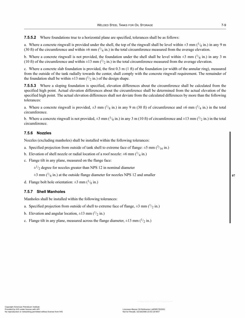
WELDED STEEL TANKS FOR OIL STORAGE 7-9
07
Copyright AmericaProvided by IHS uNo reproduction o
7.5.5.2 Where foundations true to a horizontal plane are specified, tolerances shall be as follows:
a. Where a concrete ringwall is provided under the shell, the top of the ringwall shall be level within ±3 mm (1/8 in.) in any 9 m(30 ft) of the circumference and within ±6 mm (1/4 in.) in the total circumference measured from the average elevation.
b. Where a concrete ringwall is not provided, the foundation under the shell shall be level within ±3 mm (1/8 in.) in any 3 m(10 ft) of the circumference and within ±13 mm (1/2 in.) in the total circumference measured from the average elevation.
c. Where a concrete slab foundation is provided, the first 0.3 m (1 ft) of the foundation (or width of the annular ring), measuredfrom the outside of the tank radially towards the center, shall comply with the concrete ringwall requirement. The remainder ofthe foundation shall be within ±13 mm (1/2 in.) of the design shape.
7.5.5.3 Where a sloping foundation is specified, elevation differences about the circumference shall be calculated from thespecified high point. Actual elevation differences about the circumference shall be determined from the actual elevation of thespecified high point. The actual elevation differences shall not deviate from the calculated differences by more than the followingtolerances:
a. Where a concrete ringwall is provided, ±3 mm (1/8 in.) in any 9 m (30 ft) of circumference and ±6 mm (1/4 in.) in the totalcircumference.b. Where a concrete ringwall is not provided, ±3 mm (1/8 in.) in any 3 m (10 ft) of circumference and ±13 mm (1/2 in.) in the totalcircumference.
7.5.6 Nozzles
Nozzles (excluding manholes) shall be installed within the following tolerances:
a. Specified projection from outside of tank shell to extreme face of flange: ±5 mm (3/16 in.)b. Elevation of shell nozzle or radial location of a roof nozzle: ±6 mm (1/4 in.)c. Flange tilt in any plane, measured on the flange face:
±1/2 degree for nozzles greater than NPS 12 in nominal diameter
±3 mm (1/8 in.) at the outside flange diameter for nozzles NPS 12 and smaller
d. Flange bolt hole orientation: ±3 mm (1/8 in.)
7.5.7 Shell Manholes
Manholes shall be installed within the following tolerances:
a. Specified projection from outside of shell to extreme face of flange, ±3 mm (1/2 in.)
b. Elevation and angular location, ±13 mm (1/2 in.)
c. Flange tilt in any plane, measured across the flange diameter, ±13 mm (1/2 in.)
n Petroleum Institute nder license with API Licensee=Bazan Oil Refineries Ltd/5957352001
Not for Resale, 02/18/2008 23:53:18 MSTr networking permitted without license from IHS
--``,,,,,,`,,`,`,`,``,,````,,``-`-`,,`,,`,`,,`---

Copyright AmProvided by No reproduc
--``,,,,,,`,,`,`,`,``,,````,,``-`-`,,`,,`,`,,`---
erican Petroleum Institute IHS under license with API Licensee=Bazan Oil Refineries Ltd/5957352001
Not for Resale, 02/18/2008 23:53:18 MSTtion or networking permitted without license from IHS

07
Copyright AmericaProvided by IHS uNo reproduction o
SECTION 8—METHODS OF INSPECTING JOINTS
Note: In this Standard, the term inspector, as used in Sections V and VIII of the ASME Code, shall be interpreted to mean the Purchaser’sinspector.
8.1 RADIOGRAPHIC METHOD
For the purposes of this paragraph, plates shall be considered of the same thickness when the difference in their specified ordesign thickness does not exceed 3 mm (1/8 in.).
8.1.1 Application
Radiographic inspection is required for shell butt-welds (see 8.1.2.2, 8.1.2.3, and 8.1.2.4), annular-plate butt-welds (see 8.1.2.9),and flush-type connections with butt-welds (see 5.7.8.11). Radiographic inspection is not required for the following: roof-platewelds, bottom-plate welds, welds joining the top angle to either the roof or shell, welds joining the shell plate to the bottom plate,welds in nozzle and manway necks made from plate, or appurtenance welds to the tank.
8.1.2 Number and Location of Radiographs
8.1.2.1 Except when omitted under the provisions of A.3.4, radiographs shall be taken as specified in 8.1.2 through 8.1.9.
8.1.2.2 The following requirements apply to vertical joints:
a. For butt-welded joints in which the thinner shell plate is less than or equal to 10 mm (3/8 in.) thick, one spot radiograph shall betaken in the first 3 m (10 ft) of completed vertical joint of each type and thickness welded by each welder or welding operator. Thespot radiographs taken in the vertical joints of the lowest course may be used to meet the requirements of Note 3 in Figure 8-1 forindividual joints. Thereafter, without regard to the number of welders or welding operators, one additional spot radiograph shallbe taken in each additional 30 m (100 ft) (approximately) and any remaining major fraction of vertical joint of the same type andthickness. At least 25% of the selected spots shall be at junctions of vertical and horizontal joints, with a minimum of two suchintersections per tank. In addition to the foregoing requirements, one random spot radiograph shall be taken in each vertical jointin the lowest course (see the top panel of Figure 8-1).
b. For butt-welded joints in which the thinner shell plate is greater than 10 mm (3/8 in.) but less than or equal to 25 mm (1 in.) inthickness, spot radiographs shall be taken according to Item a. In addition, all junctions of vertical and horizontal joints in platesin this thickness range shall be radiographed; each film shall clearly show not less than 75 mm (3 in.) of vertical weld and 50 mm(2 in.) of weld length on each side of the vertical intersection. In the lowest course, two spot radiographs shall be taken in eachvertical joint: one of the radiographs shall be as close to the bottom as is practicable, and the other shall be taken at random (seethe center panel of Figure 8-1).
c. Vertical joints in which the shell plates are greater than 25 mm (1 in.) thick shall be fully radiographed. All junctions of verticaland horizontal joints in this thickness range shall be radiographed; each film shall clearly show not less than 75 mm (3 in.) of ver-tical weld and 50 mm (2 in.) of weld length on each side of the vertical intersection (see the bottom panel of Figure 8-1).
d. The butt-weld around the periphery of an insert manhole or nozzle shall be completely radiographed.
8.1.2.3 One spot radiograph shall be taken in the first 3 m (10 ft) of completed horizontal butt joint of the same type and thick-ness (based on the thickness of the thinner plate at the joint) without regard to the number of welders or welding operators. There-after, one radiograph shall be taken in each additional 60 m (200 ft) (approximately) and any remaining major fraction ofhorizontal joint of the same type and thickness. These radiographs are in addition to the radiographs of junctions of vertical jointsrequired by Item c of 8.1.2.2 (see Figure 8-1).
8.1.2.4 The number of spot radiographs required herein shall be applicable on a per tank basis, irrespective of the number oftanks being erected concurrently or continuously at any location.
8.1.2.5 It is recognized that in many cases the same welder or welding operator does not weld both sides of a butt joint. If twowelders or welding operators weld opposite sides of a butt joint it is permissible to inspect their work with one spot radiograph. Ifthe radiograph is rejected, additional spot radiographs shall be taken to determine whether one or both of the welders or weldingoperators are at fault.
--``,,,,,,`,,`,`,`,``,,````,,``-`-`,,`,,`,`,,`---
8-1
n Petroleum Institute nder license with API Licensee=Bazan Oil Refineries Ltd/5957352001
Not for Resale, 02/18/2008 23:53:18 MSTr networking permitted without license from IHS

8-2 API STANDARD 650
Copyright AmProvided by No reproduc
Figure 8-1—Radiographic Requirements for Tank Shells
Top of shell
Top of shell
Tank bottom
Tank bottom
Tank bottom
(Numbers in squares refer to notes below)
1
2 1
2
33
3
1
1 2
3
4
150 mm (6")
50 mm (2")
75 mm (3")
75 mm (3")75 mm (3")
50 mm (2")1
2
33
4 4 4
5 5 5
1
4 4
² 10 mm (3/8")
> 10 mm (3/8")CL
> 10 mm (3/8")
1
22
2
4
4 4 4 4 4 4
444
2 4
44
44 4 4 4 4
42
66 6
6 6 6
PLATE THICKNESS ≤ 10 mm (3/8")
10 mm (3/8") < PLATE THICKNESS ≤ 25 mm (1")
PLATE THICKNESS > 25 mm (1")
≤ 25 mm (1")
> 25 mm (1")
150 mm (6")
25 mm (1") maximum
10 mm (3/8") maximum
CL50 mm
(2")
50 mm(2")
Notes:1. Vertical spot radiograph in accordance with 8.1.2.2, Item a: one in the first 3 m (10 ft) and one in each 30 m (100 ft)
thereafter, 25% of which shall be at intersections.2. Horizontal spot radiograph in accordance with 8.1.2.3: one in the first 3 m (10 ft) and one in each 60 m (200 ft) thereafter.3. Vertical spot radiograph in each vertical seam in the lowest course (see 8.1.2.2, Item b). Spot radiographs that satisfy the
requirements of Note 1 for the lowest course may be used to satisfy this requirement.4. Spot radiographs of all intersections over 10 mm (3/8 in.) (see 8.1.2.2, Item b).5. Spot radiograph of bottom of each vertical seam in lowest shell course over 10 mm (3/8 in.) (see 8.1.2.2, Item b).6. Complete radiograph of each vertical seam over 25 mm (1 in.). The complete radiograph may include the spot radiographs
of the intersections if the film has a minimum width of 100 mm (4 in.) (see 8.1.2.2, Item c).
--``,,,,,,`,,`,`,`,``,,````,,``-`-`,,`,,`,`,,`---
erican Petroleum Institute IHS under license with API Licensee=Bazan Oil Refineries Ltd/5957352001
Not for Resale, 02/18/2008 23:53:18 MSTtion or networking permitted without license from IHS

WELDED STEEL TANKS FOR OIL STORAGE 8-3
•
07
•
•
Copyright AmericaProvided by IHS uNo reproduction o
8.1.2.6 An equal number of spot radiographs shall be taken from the work of each welder or welding operator in proportion tothe length of joints welded.
8.1.2.7 As welding progresses, radiographs shall be taken as soon as it is practicable. The locations where spot radiographs areto be taken may be determined by the Purchaser’s inspector.
8.1.2.8 Each radiograph shall clearly show a minimum of 150 mm (6 in.) of weld length. The film shall be centered on the weldand shall be of sufficient width to permit adequate space for the location of identification marks and an image quality indicator(IQI) penetrameter.
8.1.2.9 When bottom annular plates are required by 5.5.1, or by M.4.1, the radial joints shall be radiographed as follows: (a)For double-welded butt joints, one spot radiograph shall be taken on 10% of the radial joints; (b) For single-welded butt jointswith permanent or removable back-up bar, one spot radiograph shall be taken on 50% of the radial joints. Extra care must be exer-cised in the interpretation of radiographs of single-welded joints that have a permanent back-up bar. In some cases, additionalexposures taken at an angle may determine whether questionable indications are acceptable. The minimum radiographic length ofeach radial joint shall be 150 mm (6 in.). Locations of radiographs shall preferably be at the outer edge of the joint where the shellplate and annular plate join.
8.1.3 Technique
8.1.3.1 Except as modified in this section, the radiographic examination method employed shall be in accordance withSection V, Article 2, of the ASME Code.
8.1.3.2 Personnel who perform and evaluate radiographic examinations according to this section shall be qualified and certifiedby the Manufacturer as meeting the requirements of certification as generally outlined in Level II or Level III of ASNT SNT-TC-1A (including applicable supplements). Level-I personnel may be used if they are given written acceptance/rejection proceduresprepared by Level-II or Level-III personnel. These written procedures shall contain the applicable requirements of Section V, Arti-cle 2, of the ASME Code. In addition, all Level-I personnel shall be under the direct supervision of Level-II or Level-III personnel.
8.1.3.3 The requirements of T-285 in Section V, Article 2, of the ASME Code are to be used only as a guide. Final acceptanceof radiographs shall be based on whether the prescribed penetrameter image and the specified hole can be seen.
8.1.3.4 The finished surface of the weld reinforcement at the location of the radiograph shall either be flush with the plate orhave a reasonably uniform crown not to exceed the following values:
8.1.4 Submission of Radiographs
Before any welds are repaired, the radiographs shall be submitted to the inspector with any information requested by the inspectorregarding the radiographic technique used.
8.1.5 Radiographic Standards
Welds examined by radiography shall be judged as acceptable or unacceptable by the standards of Paragraph UW-51(b) in Sec-tion VIII of the ASME Code.
8.1.6 Determination of Limits of Defective Welding
When a section of weld is shown by a radiograph to be unacceptable under the provisions of 8.1.5 or the limits of the deficientwelding are not defined by the radiograph, two spots adjacent to the section shall be examined by radiography; however, if theoriginal radiograph shows at least 75 mm (3 in.) of acceptable weld between the defect and any one edge of the film, an additionalradiograph need not be taken of the weld on that side of the defect. If the weld at either of the adjacent sections fails to complywith the requirements of 8.1.5, additional spots shall be examined until the limits of unacceptable welding are determined, or the
Plate Thicknessmm (in.)
Maximum Thickness of Reinforcementmm (in.)
≤ 13 (1/2) 1.5 (1/16)
> 13 (1/2) to 25 (1) 2.5 (3/32)
> 25 (1) 3 (1/8)--``,,,,,,`,,`,`,`,``,,````,,``-`-`,,`,,`,`,,`---
n Petroleum Institute nder license with API Licensee=Bazan Oil Refineries Ltd/5957352001
Not for Resale, 02/18/2008 23:53:18 MSTr networking permitted without license from IHS

8-4 API STANDARD 650
•
•
•
Copyright AmProvided by No reproduc
erector may replace all of the welding performed by the welder or welding operator on that joint. If the welding is replaced, theinspector shall have the option of requiring that one radiograph be taken at any selected location on any other joint on which thesame welder or welding operator has welded. If any of these additional spots fail to comply with the requirements of 8.1.5, thelimits of unacceptable welding shall be determined as specified for the initial section.
8.1.7 Repair of Defective Welds
8.1.7.1 Defects in welds shall be repaired by chipping or melting out the defects from one side or both sides of the joint, asrequired, and rewelding. Only the cutting out of defective joints that is necessary to correct the defects is required.
8.1.7.2 All repaired welds in joints shall be checked by repeating the original inspection procedure and by repeating one of thetesting methods of 7.3, subject to the approval of the Purchaser.
8.1.8 Record of Radiographic Examination
8.1.8.1 The Manufacturer shall prepare an as-built radiograph map showing the location of all radiographs taken along with thefilm identification marks.
8.1.8.2 After the structure is completed, the films shall be the property of the Purchaser unless otherwise agreed upon by thePurchaser and the Manufacturer.
8.2 MAGNETIC PARTICLE EXAMINATION
8.2.1 When magnetic particle examination is specified, the method of examination shall be in accordance with Section V, Arti-cle 7, of the ASME Code.
8.2.2 Magnetic particle examination shall be performed in accordance with a written procedure that is certified by the Manu-facturer to be in compliance with the applicable requirements of Section V of the ASME Code.
8.2.3 The Manufacturer shall determine that each magnetic particle examiner meets the following requirements:
a. Has vision (with correction, if necessary) to be able to read a Jaeger Type 2 standard chart at a distance of not less than 300 mm(12 in.) and is capable of distinguishing and differentiating contrast between the colors used. Examiners shall be checked annuallyto ensure that they meet these requirements.
b. Is competent in the technique of the magnetic particle examination method, including performing the examination and inter-preting and evaluating the results; however, where the examination method consists of more than one operation, the examinerneed only be qualified for one or more of the operations.
8.2.4 Acceptance standards and the removal and repair of defects shall be in accordance with Section VIII, Appendix 6, Para-graphs 6-3, 6-4, and 6-5, of the ASME Code.
8.3 ULTRASONIC EXAMINATION
8.3.1 Ultrasonic Examination in Lieu of Radiography
When ultrasonic examination is applied in order to fulfill the requirement of 7.3.2.1, the provisions of Appendix U shall apply.
8.3.2 Ultrasonic Examination NOT in Lieu of Radiography
8.3.2.1 When the radiographic method is applied in order to fulfill the requirement of 7.3.2.1, then any ultrasonic examinationspecified shall be in accordance with this section.
8.3.2.2 The method of examination shall be in accordance with Section V, Article 5, of the ASME Code.
8.3.2.3 Ultrasonic examination shall be performed in accordance with a written procedure that is certified by the Manufacturerto be in compliance with the applicable requirements of Section V of the ASME Code.
8.3.2.4 Examiners who perform ultrasonic examinations under this section shall be qualified and certified by the Manufactur-ers as meeting the requirements of certification as generally outlined in Level II or Level III of ASNT SNT-TC-1A (includingapplicable supplements). Level-I personnel may be used if they are given written acceptance/rejection criteria prepared by Level-II or Level-III personnel. In addition, all Level-I personnel shall be under the direct supervision of Level-II or Level-III personnel.
8.3.2.5 Acceptance standards shall be agreed upon by the Purchaser and the Manufacturer.
erican Petroleum Institute IHS under license with API Licensee=Bazan Oil Refineries Ltd/5957352001
Not for Resale, 02/18/2008 23:53:18 MSTtion or networking permitted without license from IHS
--``,,,,,,`,,`,`,`,``,,````,,``-`-`,,`,,`,`,,`---

WELDED STEEL TANKS FOR OIL STORAGE 8-5
07
07
Copyright AmericaProvided by IHS uNo reproduction o
8.4 LIQUID PENETRANT EXAMINATION
8.4.1 When liquid penetrant examination is specified, the method of examination shall be in accordance with Section V,Article 6, of the ASME Code.
8.4.2 Liquid penetrant examination shall be performed in accordance with a written procedure that is certified by the Manufac-turer to be in compliance with the applicable requirements of Section V of the ASME Code.
8.4.3 The Manufacturer shall determine and certify that each liquid penetrant examiner meets the following requirements:
a. Has vision (with correction, if necessary) to enable him to read a Jaeger Type 2 standard chart at a distance of not less than300 mm (12 in.) and is capable of distinguishing and differentiating contrast between the colors used. Examiners shall be checkedannually to ensure that they meet these requirements.
b. Is competent in the technique of the liquid penetrant examination method for which he is certified, including making the exam-ination and interpreting and evaluating the results; however, where the examination method consists of more than one operation,the examiner may be certified as being qualified for one or more of the operations.
8.4.4 Acceptance standards and the removal and repair of defects shall be in accordance with Section VIII, Appendix 8, Para-graphs 8-3, 8-4, and 8-5, of the ASME Code.
8.5 VISUAL EXAMINATION
8.5.1 A weld shall be acceptable by visual inspection if the inspection shows the following:
a. There are no crater cracks, other surface cracks or arc strikes in or adjacent to the welded joints.
b. Maximum permissible undercut is 0.4 mm (1/64 in.) in depth for vertical butt joints, vertically oriented permanent attachments,attachment welds for nozzles, manholes, flush-type openings, and the inside shell-to-bottom welds. For horizontal butt joints, hor-izontally oriented permanent attachments, and annular-ring butt joints, the maximum permissible undercut is 0.8 mm (1/32 in.) indepth.
c. The frequency of surface porosity in the weld does not exceed one cluster (one or more pores) in any 100 mm (4 in.) of length,and the diameter of each cluster does not exceed 2.5 mm (3/32 in.).
d. The reinforcement of the welds on all butt joints on each side of the plate shall not exceed the following thicknesses:
The reinforcement need not be removed except to the extent that it exceeds the maximum acceptable thickness or unless itsremoval is required by 8.1.3.4 for radiographic examination.
8.5.2 A weld that fails to meet the criteria given in 8.5.1 shall be reworked before hydrostatic testing as follows:
a. Any defects shall be removed by mechanical means or thermal gouging processes. Arc strikes discovered in or adjacent towelded joints shall be repaired by grinding and rewelding as required. Arc strikes repaired by welding shall be ground flush withthe plate.b. Rewelding is required if the resulting thickness is less than the minimum required for design or hydrostatic test conditions. Alldefects in areas thicker than the minimum shall be feathered to at least a 4:1 taper.c. The repair weld shall be visually examined for defects.
Notes:1. Vertical spot radiograph in accordance with 8.1.2.2, Item a: one in the first 3 m (10 ft) and one in each 30 m (100 ft) thereafter, 25% of
which shall be at intersections.
Plate Thicknessmm (in.)
Maximum Reinforcement Thicknessmm (in.)
Vertical Joints Horizontal Joints
≤ 13 (1/2) 2.5 (3/32) 3 (1/8)
> 13 (1/2) to 25 (1) 3 (1/8) 5 (3/16)
> 25 (1) 5 (3/16) 6 (1/4)--``,,,,,,`,,`,`,`,``,,````,,``-`-`,,`,,`,`,,`---
n Petroleum Institute nder license with API Licensee=Bazan Oil Refineries Ltd/5957352001
Not for Resale, 02/18/2008 23:53:18 MSTr networking permitted without license from IHS

8-6 API STANDARD 650
•
07
•
Copyright AmProvided by No reproduc
2. Horizontal spot radiograph in accordance with 8.1.2.3: one in the first 3 m (10 ft) and one in each 60 m (200 ft) thereafter.3. Vertical spot radiograph in each vertical seam in the lowest course (see 8.1.2.2, Item b). Spot radiographs that satisfy the requirements of
Note 1 for the lowest course may be used to satisfy this requirement.4. Spot radiographs of all intersections over 10 mm (3/8 in.) (see 8.1.2.2, Item b).5. Spot radiograph of bottom of each vertical seam in lowest shell course over 10 mm (3/8 in.) (see 8.1.2.2, Item b).6. Complete radiograph of each vertical seam over 25 mm (1 in.). The complete radiograph may include the spot radiographs of the intersec-
tions if the film has a minimum width of 100 mm (4 in.) (see 8.1.2.2, Item c).
8.6 VACUUM TESTING
8.6.1 Vacuum testing is performed using a testing box approximately 150 mm (6 in.) wide by 750 mm (30 in.) long with a clearwindow in the top, which provides proper visibility to view the area under inspection. During testing, illumination shall be ade-quate for proper evaluation and interpretation of the test. The open bottom shall be sealed against the tank surface by a suitablegasket. Connections, valves, lighting and gauges, as required, shall be provided. A soap film solution or commercial leak detec-tion solution, applicable to the conditions, shall be used.
8.6.2 Vacuum testing shall be performed in accordance with a written procedure prepared by the Manufacturer of the tank. Theprocedure shall require:
a. Performing a visual examination of the bottom and welds prior to performing the vacuum-box test;
b. Verifying the condition of the vacuum box and its gasket seals;c. Verifying that there is no quick bubble or spitting response to large leaks; and
d. Applying the film solution to a dry area, such that the area is thoroughly wetted and a minimum generation of application bub-bles occurs.
8.6.3 A partial vacuum of 21 kPa (3 lbf/in.2/6 in. Hg) to 35 kPa (5 lbf/in.2/10 in Hg) gauge shall be used for the test. If specifiedby the Purchaser, a second partial vacuum test of 56 kPa (8 lbf/in.2/16 in. Hg) to 70 kPa (10 lbf/in.2/20 in. Hg) shall be performedfor the detection of very small leaks.
8.6.4 The Manufacturer shall determine that each vacuum-box operator meets the following requirements:
a. Has vision (with correction, if necessary) to be able to read a Jaeger Type 2 standard chart at a distance of not less than 300 mm(12 in.). Operators shall be checked annually to ensure that they meet this requirement; and
b. Is competent in the technique of the vacuum-box testing, including performing the examination and interpreting and evaluat-ing the results; however, where the examination method consists of more than one operation, the operator performing only aportion of the test need only be qualified for that portion the operator performs.
8.6.5 The vacuum-box test shall have at least 50 mm (2 in.) overlap of previously viewed surface on each application.
8.6.6 The metal surface temperature limits shall be between 4°C (40°F) and 52°C (125°F), unless the film solution is proven towork at temperatures outside these limits, either by testing or Manufacturer’s recommendations.
8.6.7 A minimum light intensity of 1000 Lux (100 fc) at the point of examination is required during the application of theexamination and evaluation for leaks.
8.6.8 The vacuum shall be maintained for the greater of either at least 5 seconds or the time required to view the area under test.
8.6.9 The presence of a through-thickness leak indicated by continuous formation or growth of a bubble(s) or foam, producedby air passing through the thickness, is unacceptable. The presence of a large opening leak, indicated by a quick bursting bubbleor spitting response at the initial setting of the vacuum box is unacceptable. Leaks shall be repaired and retested.
8.6.10 A record or report of the test including a statement addressing temperature and light intensity shall be completed andfurnished to the Purchaser upon request.
8.6.11 As an alternate to vacuum-box testing, a suitable tracer gas and compatible detector can be used to test the integrity ofwelded bottom joints for their entire length. Where tracer gas testing is employed as an alternate to vacuum-box testing, it shallmeet the following requirements:
•
--``,,,,,,`,,`,`,`,``,,````,,``-`-`,,`,,`,`,,`---
erican Petroleum Institute IHS under license with API Licensee=Bazan Oil Refineries Ltd/5957352001
Not for Resale, 02/18/2008 23:53:18 MSTtion or networking permitted without license from IHS

WELDED STEEL TANKS FOR OIL STORAGE 8-7
Copyright AmericaProvided by IHS uNo reproduction o
a. Tracer gas testing shall be performed in accordance with a written procedure which has been reviewed and approved by thePurchaser and which shall address as a minimum: the type of equipment used, surface cleanliness, type of tracer gas, test pressure,soil permeability, soil moisture content, satisfactory verification of the extent of tracer gas permeation, and the method or tech-nique to be used including scanning rate and probe standoff distance.b. The technique shall be capable of detecting leakage of 1 × 10⁻⁴ Pa m3/s (1 × 10⁻³ std cm3/s) or smaller c. The test system parameters (detector, gas, and system pressure, i.e., level of pressure under bottom) shall be calibrated by plac-ing the appropriate calibrated capillary leak, which will leak at a rate consistent with (b) above, in a temporary or permanentfitting in the tank bottom away from the tracer gas pressurizing point. Alternatively, by agreement between the Purchaser and theManufacturer, the calibrated leak may be placed in a separate fitting pressurized in accordance with the system parameters. d. While testing for leaks in the welded bottom joints, system parameters shall be unchanged from those used during calibration.
n Petroleum Institute nder license with API Licensee=Bazan Oil Refineries Ltd/5957352001
Not for Resale, 02/18/2008 23:53:18 MSTr networking permitted without license from IHS
--``,,,,,,`,,`,`,`,``,,````,,``-`-`,,`,,`,`,,`---

Copyright AmProvided by No reproduc
--``,,,,,,`,,`,`,`,``,,````,,``-`-`,,`,,`,`,,`---
erican Petroleum Institute IHS under license with API Licensee=Bazan Oil Refineries Ltd/5957352001
Not for Resale, 02/18/2008 23:53:18 MSTtion or networking permitted without license from IHS

•
Copyright AmericaProvided by IHS uNo reproduction o
SECTION 9—WELDING PROCEDURE AND WELDER QUALIFICATIONS
9.1 DEFINITIONS
In this Standard, terms relating to welding shall be interpreted as defined in Section IX of the ASME Code. Additional terms aredefined in 9.1.1 and 9.1.2.
9.1.1 An angle joint is a joint between two members that intersect at an angle between 0 degrees (a butt joint) and 90 degrees (acorner joint).
9.1.2 Porosity refers to gas pockets or voids in metal.
9.2 QUALIFICATION OF WELDING PROCEDURES
9.2.1 General Requirements
9.2.1.1 The erection Manufacturer and the fabrication Manufacturer if other than the erection Manufacturer, shall preparewelding procedure specifications and shall perform tests documented by procedure qualification records to support the specifica-tions, as required by Section IX of the ASME Code and any additional provisions of this Standard. If the Manufacturer is part ofan organization that has, to the Purchaser’s satisfaction, established effective operational control of the qualification of weldingprocedures and of welder performance for two or more companies of different names, then separate welding procedure qualifica-tions are not required, provided all other requirements of 9.2, 9.3, and Section IX of the ASME Code are met. Welding proceduresfor ladder and platform assemblies, handrails, stairways, and other miscellaneous assemblies, but not their attachments to thetank, shall comply with either AWS D1.1, AWS D1.6, or Section IX of the ASME Code, including the use of standard WPSs.
9.2.1.2 The welding procedures used shall produce weldments with the mechanical properties required by the design.
9.2.1.3 Material specifications listed in Section 4 of this Standard but not included in Table QW-422 of Section IX of theASME Code shall be considered as P1 material with group numbers assigned as follows according to the minimum tensilestrength specified:
a. Less than or equal to 485 MPa (70 ksi)—Group 1.b. Greater than 485 MPa (70 ksi) but less than 550 MPa (80 ksi)—Group 2.c. Greater than or equal to 550 MPa (80 ksi)—Group 3.
Separate welding procedures and performance qualifications shall be conducted for A 841M/A 841 material.
9.2.1.4 Welding variables (including supplementary essential variables when impact tests are required by 9.2.2), as defined byQW-250 of Section IX of the ASME Code, shall be used to determine the welding procedure specifications and the procedurequalification records to be instituted. In addition, when impact tests of the heat-affected zone are required, the heat-treated condi-tion of the base material shall be a supplementary essential variable. If a protective coating has been applied to weld edge prepa-rations, the coating shall be included as an essential variable of the welding procedure specification, as required by 7.2.1.9.
9.2.2 Impact Tests
9.2.2.1 Impact tests for the qualification of welding procedures shall comply with the applicable provisions of 4.2.8 and shallbe made at or below the design metal temperature.
9.2.2.2 When impact testing of a material is required by 4.2.8, 4.2.9, or 4.5.5, impact tests of the heat-affected zone shall bemade for all automatic and semiautomatic welding procedures.
9.2.2.3 For all materials to be used at a design metal temperature below 10°C (50°F), the qualification of the welding procedurefor vertical joints shall include impact tests of the weld metal. If vertical joints are to be made by an automatic or semiautomaticprocess, impact tests of the heat-affected zone shall also be made.
9.2.2.4 When the design metal temperature is below –7°C (20°F), impact tests of the weld metal shall be made for all proce-dures used for welding the components listed in 4.2.9.1, for welding attachments to these components, and for fabricating shellnozzles and manholes from pipe and forgings listed in 4.5.
9-1
n Petroleum Institute nder license with API Licensee=Bazan Oil Refineries Ltd/5957352001
Not for Resale, 02/18/2008 23:53:18 MSTr networking permitted without license from IHS
--``,,,,,,`,,`,`,`,``,,````,,``-`-`,,`,,`,`,,`---

9-2 API STANDARD 650
Copyright AmProvided by No reproduc
--``,,,,,,`,,`,`,`,``,,````,,``-`-`,,`,,`,`,,`---
9.2.2.5 Impact tests shall show minimum values for acceptance in accordance with 4.2.8.3 and the following:
a. For P1, Group 1, materials—20 J (15 ft-lbf), average of three specimens.b. For P1, Group 2, materials—27 J (20 ft-lbf), average of three specimens.c. For P1, Group 3, materials—34 J (25 ft-lbf), average of three specimens.
For shell plates thicker than 40 mm (11/2 in.), these values shall be increased by 7 J (5 ft-lbf) for each 12.5 mm (1/2 in.) over40 mm (11/2 in.). Interpolation is permitted.
9.2.2.6 Weld-metal impact specimens shall be taken across the weld with one face substantially parallel to and within 1.5 mm(1/16 in.) of the surface of the material. The notch shall be cut normal to the original material surface and with the weld metalentirely within the fracture zone.
9.2.2.7 Heat-affected-zone impact specimens shall be taken across the weld and as near the surface of the material as is practi-cable. Each specimen shall be etched to locate the heat-affected zone, and the notch shall be cut approximately normal to the orig-inal material surface and with as much heat-affected-zone material as possible included in the fracture zone.
9.2.2.8 Production welding shall conform to the qualified welding procedure, but production-weld test plates need not bemade.
9.3 QUALIFICATION OF WELDERS
9.3.1 The erection Manufacturer and the fabrication Manufacturer, if other than the erection Manufacturer, shall conduct testsfor all welders assigned to manual and semiautomatic welding and all operators assigned to automatic welding to demonstrate thewelders’ and operators’ ability to make acceptable welds. Tests conducted by one Manufacturer shall not qualify a welder orwelding operator to do work for another Manufacturer.
9.3.2 The welders and welding operators who weld pressure parts and join nonpressure parts, such as all permanent and tempo-rary clips and lugs, to pressure parts shall be qualified in accordance with Section IX of the ASME Code.
9.3.3 The records of the tests for qualifying welders and welding operators shall include the following:
a. Each welder or welding operator shall be assigned an identifying number, letter, or symbol by the fabrication or erectionManufacturer.b. The fabrication or erection Manufacturer shall maintain a record of the welders or welding operators employed that shows thedate and results of the tests for each welder or operator and the identifying mark assigned to each welder or operator. This recordshall be certified by the fabrication or erection Manufacturer and shall be accessible to the inspector.
9.4 IDENTIFICATION OF WELDED JOINTS
The welder or welding operator’s identification mark shall be hand- or machine-stamped adjacent to and at intervals not exceed-ing 1 m (3 ft) along the completed welds. In lieu of stamping, a record may be kept that identifies the welder or welding operatoremployed for each welded joint; these records shall be accessible to the inspector. Roof plate welds and flange-to-nozzle-neckwelds do not require welder identification.
erican Petroleum Institute IHS under license with API Licensee=Bazan Oil Refineries Ltd/5957352001
Not for Resale, 02/18/2008 23:53:18 MSTtion or networking permitted without license from IHS

•••
• 07
•
07
Copyright AmericaProvided by IHS uNo reproduction o
SECTION 10—MARKING
10.1 NAMEPLATES
10.1.1 A tank made in accordance with this Standard shall be identified by a nameplate similar to that shown in Figure 10-1.The nameplate shall indicate, by means of letters and numerals not less than 4 mm (5/32 in.) high, the following information:
a. API Standard 650.b. The applicable appendix to API Standard 650.c. The year the tank was completed.d. The date of the edition and the addendum number of API Standard 650.e. The nominal diameter and nominal height, in meters (ft and in.) (unless other units are specified by the Purchaser).f. The maximum capacity (see 5.2.6.2), in m3 (42-gallon barrels) (unless other units are specified by the Purchaser).g. The design liquid level (see 5.6.3.2), in meters (ft and in.) (unless other units are specified by the Purchaser).h. The design specific gravity of the liquid.i. The design pressure, which shall be shown as atmospheric unless Appendix F or Appendix V applies. If Appendix V applies,design pressure shall be shown as a negative number. If both Appendices F and V apply, the positive and negative pressures shallbe separated by a forward slash and shall be followed by consistent units of measurement.j. The design metal temperature as described in 1.4 in °C (°F), unless other units are specified by the Purchaser.k. The maximum design temperature, in °C (°F) (unless other units are specified by the Purchaser), which shall not exceed 93°C(200°F) except in cases where Appendix M applies.l. The name of the fabrication Manufacturer if other than the erection Manufacturer. The Manufacturer’s serial number or con-tract number shall be from the erection Manufacturer.m. The material specification number for each shell course.n. When stress relief is applied to a part in accordance with the requirements of 5.7.4, the letters “SR.”o. The Purchaser’s tank number.
API STANDARD 650
APPENDIX
EDITION
NOMINAL DIAMETER
MAXIMUM CAPACITY
DESIGN SPECIFIC GRAVITY
DESIGN PRESSURE
MANUFACTURER’S SERIAL NO.
FABRICATED BY
ERECTED BY
YEAR COMPLETED
ADDENDUM NO.
NOMINAL HEIGHT
DESIGN LIQUID LEVEL
MAXIMUM DESIGN TEMP.
DESIGN METAL TEMP.
PARTIAL STRESS RELIEF
PURCHASER’S TANK NO.
SHELL COURSE MATERIAL
Figure 10-1—Manufacturer’s Nameplate
Note: At the Purchaser’s request or at the erection Manufacturer’s discretion, additional pertinent information may be shown on the nameplate, and the size of the nameplate may be increased proportionately.
•
--``,,,,,,`,,`,`,`,``,,````,,``-`-`,,`,,`,`,,`---
10-1
n Petroleum Institute nder license with API Licensee=Bazan Oil Refineries Ltd/5957352001
Not for Resale, 02/18/2008 23:53:18 MSTr networking permitted without license from IHS

10-2 API STANDARD 650
•
Copyright AmProvided by No reproduc
10.1.2 The nameplate shall be attached to the tank shell adjacent to a manhole or to a manhole reinforcing plate immediatelyabove a manhole. A nameplate that is placed directly on the shell plate or reinforcing plate shall be attached by continuous weld-ing or brazing all around the nameplate. A nameplate that is riveted or otherwise permanently attached to an auxiliary plate of fer-rous material shall be attached to the tank shell plate or reinforcing plate by continuous welding. The nameplate shall be ofcorrosion-resistant metal.
10.1.3 When a tank is fabricated and erected by a single organization, that organization’s name shall appear on the nameplateas both fabricator and erector.
10.1.4 When a tank is fabricated by one organization and erected by another, the names of both organizations shall appear onthe nameplate, or separate nameplates shall be applied by each.
10.2 DIVISION OF RESPONSIBILITYUnless otherwise agreed upon, when a tank is fabricated by one Manufacturer and erected by another, the erection Manufacturershall be considered as having the primary responsibility. The erection Manufacturer shall make certain that the materials used inthe fabrication of the components and in the construction of the tank are in accordance with all applicable requirements.
10.3 CERTIFICATION
The Manufacturer shall certify to the Purchaser, by a letter such as that shown in Figure 10-2, that the tank has been constructed inaccordance with the applicable requirements of this Standard. An as-built data sheet in accordance with Appendix L shall beattached to the certification letter.
Note: At the Purchaser’s request or at the erection Manufacturer’s discretion, additional pertinent information may be shown on the nameplate,and the size of the nameplate may be increased proportionately.
Figure 10-2—Manufacturer’s Certification Letter
MANUFACTURER’S CERTIFICATION FOR A TANK BUILT TO API STANDARD 650
To ____________________________________________________________________________________________(name and address of Purchaser)
____________________________________________________________________________________________
____________________________________________________________________________________________
We hereby certify that the tank constructed for you at ___________________________________________________(location)
______________________________________________________________________________________________
______________________________________________________________________________________________
and described as follows: _________________________________________________________________________(serial or contract number, diameter, height, capacity, floating or fixed roof)
______________________________________________________________________________________________
meets all applicable requirements of API Standard 650, ______________ Edition, ______________ Revision, Appendix
___________, dated ____________________, including the requirements for design, materials, fabrication, and erection.
The tank is further described on the attached as-built data sheet dated _________________________.
______________________________________________Manufacturer______________________________________________
Authorized Representative______________________________________________
Date
--``,,,,,,`,,`,`,`,``,,````,,``-`-`,,`,,`,`,,`---
erican Petroleum Institute IHS under license with API Licensee=Bazan Oil Refineries Ltd/5957352001
Not for Resale, 02/18/2008 23:53:18 MSTtion or networking permitted without license from IHS

•
07
•
07
•
Copyright AmericaProvided by IHS uNo reproduction o
--``,,,,,,`,,`,`,`,``,,````,,``-`-`,,`,,`,`,,`---
APPENDIX A—OPTIONAL DESIGN BASIS FOR SMALL TANKS
A.1 ScopeA.1.1 This appendix provides requirements for field-erected tanks of relatively small capacity in which the stressed compo-nents have a maximum nominal thickness of 12.5 mm (1/2 in.), including any corrosion allowance specified by the Purchaser. Thestressed components include the shell and reinforcing plates, shell reinforcing plates for flush-type cleanout fittings and flush-typeshell connections, and bottom plates that are welded to the shell. The maximum nominal thickness of 12.5 mm (1/2 in.) does notapply to:
1. bottom plates not welded to the shell,
2. the bottom reinforcing plate of flush-type cleanouts and flush-type shell connections,
3. flanges and cover plates of flush-type cleanouts,
4. flush-type shell connection necks attached to shell and flanges and cover plates of flush-type shell connections,
5. nozzle and manhole necks, their flanges and cover plates,
6. anchor bolt chair components and shell compression ring.
A.1.2 This appendix is applicable only when specified by the Purchaser and is limited to design metal temperatures above–30°C (–20°F) (above –40°C [–40°F] when killed, fine-grain material is used).
A.1.3 This appendix is applicable to any of the Section 4 materials, although the single allowable stress does not provide anyadvantage to higher strength steels.
A.1.4 This appendix states only the requirements that differ from the basic rules in this Standard. When differing requirementsare not stated, the basic rules must be followed; however, the overturning effect of a wind load should be considered.
A.1.5 Typical sizes, capacities, and shell-plate thicknesses are listed in Tables A-1 through A-4 for a design in accordance withA.4 (joint efficiency = 0.85; specific gravity = 1.0; and corrosion allowance = 0).
A.2 MaterialsA.2.1 Shell-plate materials shall not be more than 12.5 mm (1/2 in.) thick, as stated in A.1.1.
A.2.2 For stressed components, the Group-I and Group-II materials listed in Table 4-3 may be used above a design metal tem-perature of –30°C (–20°F) but need not conform to the toughness requirements of 4.2.9, Figure 4-1, and 9.2.2. Group-III andGroup-IIIA materials may be used above a design metal temperature of –40°C (–40°F) and shall conform to impact requirementsof 9.2.2.
A.2.3 Material used for shell nozzle and manhole necks and flanges shall conform to 4.5, 4.6, and Table 4-3 but need not con-form to the toughness requirements of 4.2.9, 4.5.5, and Figure 4-1.
A.2.4 Bottom reinforcing plates in flush-type cleanouts and flush-type shell connections, and flush-type fitting necks attachedto shell shall conform to toughness requirements of 4.2.9 and Figure 4-1 at design metal temperature.
A.3 DesignA.3.1 The maximum tensile stress before the joint efficiency factor is applied shall be 145 MPa (21,000 lbf/in.2).
A.3.2 Stresses shall be computed on the assumption that the tank is filled with water (specific gravity = 1.0) or with the liquid tobe stored if it is heavier than water.
A.3.3 The tension in each ring shall be computed 300 mm (12 in.) above the centerline of the lower horizontal joint of thecourse in question. When these stresses are computed, the tank diameter shall be taken as the nominal diameter of the bottomcourse.
A.3.4 The joint efficiency factor shall be 0.85 with the spot radiography required by A.5.3. By agreement between the Pur-chaser and the Manufacturer, the spot radiography may be omitted, and a joint efficiency factor of 0.70 shall be used.
A-1
n Petroleum Institute nder license with API Licensee=Bazan Oil Refineries Ltd/5957352001
Not for Resale, 02/18/2008 23:53:18 MSTr networking permitted without license from IHS

A-2 API STANDARD 650
07
Copyright AmProvided by No reproduc
Table A-1a—Typical Sizes and Corresponding Nominal Capacities (m3) for Tanks with 1800-mm Courses
Column 1 Column 2 Column 3 Column 4 Column 5 Column 6 Column 7 Column 8 Column 9 Column 10 Column 11
Tank Diameter
m
Capacity per m of Height
m3
Tank Height (m) / Number of Courses in Completed Tank
3.6 / 2 5.4 / 3 7.2 / 4 9 / 5 10.8 / 6 12.6 / 7 14.4 / 8 16.2 / 9 18 / 10
3 7.07 25 38 51 64 76 — — — —
4.5 15.9 57 86 115 143 172 — — — —
6 28.3 102 153 204 254 305 356 407 — —
7.5 44.2 159 239 318 398 477 557 636 716 795
9 63.6 229 344 458 573 687 802 916 1,031 1,145
10.5 86.6 312 468 623 779 935 1,091 1,247 1,403 1,559
12 113 407 611 814 1,018 1,221 1,425 1,629 1,832 2,036
13.5 143 515 773 1,031 1,288 1,546 1,804 2,061 2,319 2,576
15 177 636 954 1,272 1,590 1,909 2,227 2,545 2,863 3,181
18 254 916 1,374 1,832 2,290 2,748 3,206 3,664 4,122 4,580
D = 18
21 346 1,247 1,870 2,494 3,117 3,741 4,364 4,988 5,089 —
24 452 1,629 2,443 3,257 4,072 4,886 5,700 5,474 D = 20 —
27 573 2,061 3,092 4,122 5,153 6,184 6,690 D = 22 — —
30 707 2,545 3,817 5,089 6,362 7,634 D = 26 — — —
36 1,018 3,664 5,497 7,329 9,161 D = 30 — — — —
D = 36
42 1,385 4,988 7,481 9,975 — — — — — —
48 1,810 6,514 9,772 11,966 — — — — — —
54 2,290 8,245 12,367 D = 46 — — — — — —
60 2,827 10,179 15,268 — — — — — — —
66 3,421 12,316 16,303 — — — — — — —
D = 62
Note: The nominal capacities given in this table were calculated using the following formula:
In SI units:C = 0.785D2H
whereC = capacity of tank, in m3,D = diameter of tank, in m (see A.4.1),H = height of tank, in m (see A.4.1).
The capacities and diameters in italics (Columns 4 – 11) are themaximums for the tank heights given in the column heads, basedon a maximum permissible shell-plate thickness of 12.5 mm, amaximum allowable design stress of 145 MPa, a joint efficiencyof 0.85, and no corrosion allowance (see A.4.1).
erican Petroleum Institute IHS under license with API Licensee=Bazan Oil Refineries Ltd/5957352001
Not for Resale, 02/18/2008 23:53:18 MSTtion or networking permitted without license from IHS
--``,,,,,,`,,`,`,`,``,,````,,``-`-`,,`,,`,`,,`---

WELDED STEEL TANKS FOR OIL STORAGE A-3
Copyright AmericaProvided by IHS uNo reproduction o
Table A-1b—Typical Sizes and Corresponding Nominal Capacities (barrels) for Tanks with 72-in. Courses
Column 1 Column 2 Column 3 Column 4 Column 5 Column 6 Column 7 Column 8 Column 9 Column 10 Column 11
Tank Diameter
ft
Capacity per ft ofHeightbarrels
Tank Height (ft) / Number of Courses in Completed Tank
12 / 2 18 / 3 24 / 4 30 / 5 36 / 6 42 / 7 48 / 8 54 / 9 60 / 10
10 14.0 170 250 335 420 505 — — — —
15 31.5 380 565 755 945 1,130 — — — —
20 56.0 670 1,010 1,340 1,680 2,010 2,350 2,690 — —
25 87.4 1,050 1,570 2,100 2,620 3,150 3,670 4,200 4,720 5,250
30 126 1,510 2,270 3,020 3,780 4,530 5,290 6,040 6,800 7,550
35 171 2,060 3,080 4,110 5,140 6,170 7,200 8,230 9,250 10,280
40 224 2,690 4,030 5,370 6,710 8,060 9,400 10,740 12,100 13,430
45 283 3,400 5,100 6,800 8,500 10,200 11,900 13,600 15,300 17,000
50 350 4,200 6,300 8,400 10,500 12,600 14,700 16,800 18,900 21,000
60 504 6,040 9,060 12,100 15,110 18,130 21,150 24,190 37,220 28,260
D = 58
70 685 8,230 12,340 16,450 20,580 24,700 28,800 32,930 30,970 —
80 895 10,740 16,120 21,500 26,880 32,260 37,600 35,810 D = 64 —
90 1,133 13,600 20,400 27,220 34,030 40,820 40,510 D = 73 — —
100 1,399 16,800 25,200 33,600 42,000 48,400 D = 83 — — —
120 2,014 24,190 36,290 48,380 58,480 D = 98 — — — —
D = 118
140 2,742 32,930 49,350 65,860 — — — — — —
160 3,581 43,000 64,510 74,600 — — — — — —
180 4,532 54,430 81,650 D = 149 — — — — — —
200 5,595 67,200 100,800 — — — — — — —
220 6,770 81,310 102,830 — — — — — — —
D = 202
Note: The nominal capacities given in this table were calculated using the following formula:
In US Customary units:C = 0.14D2H,
whereC = capacity of tank, in 42-gal barrels,D = diameter of tank, in ft (see A.4.1),H = height of tank, in ft (see A.4.1).
The capacities and diameters in italics (Columns 4 – 11) are themaximums for the tank heights given in the column heads,based on a maximum permissible shell-plate thickness of 1/2 in.,a maximum allowable design stress of 21,000 lbf/in.2, a jointefficiency of 0.85, and no corrosion allowance (see A.4.1).
--``,,,,,,`,,`,`,`,``,,````,,``-`-`,,`,,`,`,,`---
n Petroleum Institute nder license with API Licensee=Bazan Oil Refineries Ltd/5957352001
Not for Resale, 02/18/2008 23:53:18 MSTr networking permitted without license from IHS

A-4 API STANDARD 650
Copyright AmProvided by No reproduc
Table A-2a—Shell-Plate Thicknesses (mm) for Typical Sizes of Tanks with 1800-mm Courses
Column 1 Column 2 Column 3 Column 4 Column 5 Column 6 Column 7 Column 8 Column 9 Column 10 Column 11 Column 12
Tank Diameter
m
Tank Height (m) / Number of Courses in Completed Tank
Maximum Allowable Height for Diametera
m1.8 / 1 3.6 / 2 5.4 / 3 7.2 / 4 9 / 5 10.8 / 6 12.6 / 7 14.4 / 8 16.2 / 9 18 / 10
3 5.0 5.0 5.0 5.0 5.0 5.0 — — — — —
4.5 5.0 5.0 5.0 5.0 5.0 5.0 — — — — —
6 5.0 5.0 5.0 5.0 5.0 5.0 5.0 5.0 — — —
7.5 5.0 5.0 5.0 5.0 5.0 5.0 5.0 5.0 5.0 5.3 —
9 5.0 5.0 5.0 5.0 5.0 5.0 5.0 5.0 5.7 6.3 —
10.5 5.0 5.0 5.0 5.0 5.0 5.0 5.1 5.9 6.6 7.4 —
12 5.0 5.0 5.0 5.0 5.0 5.0 5.9 6.7 7.6 8.4 —
13.5 5.0 5.0 5.0 5.0 5.0 5.6 6.6 7.6 8.5 9.5 —
15 6.0 6.0 6.0 6.0 6.0 6.3 7.3 8.4 9.5 10.6 —
18 6.0 6.0 6.0 6.0 6.2 7.5 8.8 10.1 11.4 — 17.8
21 6.0 6.0 6.0 6.0 7.3 8.8 10.3 11.8 — — 15.3
24 6.0 6.0 6.0 6.6 8.3 10.0 11.7 — — — 13.4
27 6.0 6.0 6.0 7.4 9.3 11.3 — — — — 11.9
30 6.0 6.0 6.0 8.2 10.4 12.5 — — — — 10.8
36 8.0 8.0 8.0 9.9 12.5 — — — — — 9.0
42 8.0 8.0 8.5 11.5 — — — — — — 7.8
48 8.0 8.0 9.7 — — — — — — — 6.9
54 8.0 8.0 10.9 — — — — — — — 6.1
60 8.0 8.0 12.2 — — — — — — — 5.5
66 10.0 10.0 — — — — — — — — 5.1
aBased on a maximum permissible shell-plate thickness of 12.5 mm, a maximum allowable design stress of 145 MPa, a joint efficiency of 0.85,and no corrosion allowance.Note: The plate thicknesses shown in this table are based on a maximum allowable design stress of 145 MPa, a joint efficiency of 0.85, and nocorrosion allowance (see A.4.1).
--``,,,,,,`,,`,`,`,``,,````,,``-`-`,,`,,`,`,,`---
erican Petroleum Institute IHS under license with API Licensee=Bazan Oil Refineries Ltd/5957352001
Not for Resale, 02/18/2008 23:53:18 MSTtion or networking permitted without license from IHS

WELDED STEEL TANKS FOR OIL STORAGE A-5
07
Copyright AmericaProvided by IHS uNo reproduction o
Table A-2b—Shell-Plate Thicknesses (in.) for Typical Sizes of Tanks with 72-in. Courses
Column 1 Column 2 Column 3 Column 4 Column 5 Column 6 Column 7 Column 8 Column 9 Column 10 Column 11 Column 12
Tank Diameter
ft
Tank Height (ft) / Number of Courses in Completed Tank
Maximum Allowable Height for Diametera
ft6 / 1 12 / 2 18 / 3 24 / 4 30 / 5 36 / 6 42 / 7 48 / 8 54 / 9 60 / 10
10 3/16 3/16 3/16 3/16 3/16 3/16 — — — — —
15 3/16 3/16 3/16 3/16 3/16 3/16 — — — — —
20 3/16 3/16 3/16 3/16 3/16 3/16 3/16 3/16 — — —
25 3/16 3/16 3/16 3/16 3/16 3/16 3/16 3/16 0.20 0.22 —
30 3/16 3/16 3/16 3/16 3/16 3/16 3/16 0.21 0.24 0.26 —
35 3/16 3/16 3/16 3/16 3/16 3/16 0.21 0.24 0.27 0.30 —
40 3/16 3/16 3/16 3/16 3/16 0.21 0.24 0.28 0.31 0.35 —
45 3/16 3/16 3/16 3/16 3/16 0.23 0.27 0.31 0.35 0.38 —
50 1/4 1/4 1/4 1/4 1/4 0.26 0.30 0.35 0.39 0.43 —
60 1/4 1/4 1/4 1/4 0.26 0.31 0.36 0.41 0.47 — 58.2
70 1/4 1/4 1/4 1/4 0.30 0.36 0.42 0.48 — — 50.0
80 1/4 1/4 1/4 0.27 0.34 0.41 0.48 — — — 43.9
90 1/4 1/4 1/4 0.31 0.38 0.46 — — — — 39.1
100 1/4 1/4 1/4 0.34 0.43 — — — — — 35.3
120 5/16 5/16 5/16 0.41 — — — — — — 29.6
140 5/16 5/16 0.35 0.47 — — — — — — 25.5
160 5/16 5/16 0.40 — — — — — — — 22.5
180 5/16 5/16 0.45 — — — — — — — 20.1
200 5/16 0.32 0.50 — — — — — — — 18.2
220 3/8 3/8 — — — — — — — — 16.6
aBased on a maximum permissible shell-plate thickness of 1/2 in., a maximum allowable design stress of 21,000 lbf/in.2, a joint efficiency of0.85, and no corrosion allowance.Note: The plate thicknesses shown in this table are based on a maximum allowable design stress of 21,000 lbf/in.2, a joint efficiency of 0.85, andno corrosion allowance (see A.4.1).
--``,,,,,,`,,`,`,`,``,,````,,``-`-`,,`,,`,`,,`---
n Petroleum Institute nder license with API Licensee=Bazan Oil Refineries Ltd/5957352001
Not for Resale, 02/18/2008 23:53:18 MSTr networking permitted without license from IHS

A-6 API STANDARD 650
Copyright AmProvided by No reproduc
Table A-3a—Typical Sizes and Corresponding Nominal Capacities (m3)for Tanks with 2400-mm Courses
Column 1 Column 2 Column 3 Column 4 Column 5 Column 6 Column 7 Column 8 Column 9
Tank Diameter
m
Capacity perm of Height
m3
Tank Height (m) / Number of Courses in Completed Tank
4.8 / 2 7.2 / 3 9.6 / 4 12 / 5 14.4 / 6 16.8 / 7 19.2 / 8
3 7.07 34 51 68 — — — —
4.5 15.9 76 115 153 191 — — —
6 28.3 136 204 272 339 407 — —
7.5 44.2 212 318 424 530 636 742 848
9 63.6 305 458 610 763 916 1,069 1,221
10.5 86.6 416 623 831 1,039 1,247 1,455 1,663
12 113 543 814 1085 1,357 1,629 1,900 2,171
13.5 143 687 1,031 1373 1,718 2,061 2,405 2,748
15 177 848 1,272 1696 2,121 2,545 2,969 3,393
18 254 1,221 1,832 2442 3,054 3,664 4,275 4,358
D = 17
21 346 1,663 2,494 3323 4,156 4,988 4,763 —
24 452 2,171 3,257 4341 5,429 5,474 D = 19 —
27 573 2,748 4,122 5494 6,871 D = 22 — —
30 707 3,393 5,089 6782 D = 27 — — —
36 1,018 4,886 7,329 8712 — — — —
D = 34
42 1,385 6,650 9,975 — — — — —
48 1,810 8,686 11,966 — — — — —
54 2,290 10,993 D = 46 — — — — —
60 2,827 13,572 — — — — — —
66 3,421 16,422 — — — — — —
Note: The nominal capacities given in this table werecalculated using the following formula:
In SI units:C = 0.785D2H
whereC = capacity of tank, in m3,D = diameter of tank, in m (see A.4.1),H = height of tank, in m (see A.4.1).
The capacities and diameters in italics (Columns 4 – 9) are themaximums for the tank heights given in the column heads, basedon a maximum permissible shell-plate thickness of 12.5 mm, amaximum allowable design stress of 145 MPa, a joint efficiencyof 0.85, and no corrosion allowance (see A.4.1).
erican Petroleum Institute IHS under license with API Licensee=Bazan Oil Refineries Ltd/5957352001
Not for Resale, 02/18/2008 23:53:18 MSTtion or networking permitted without license from IHS
--``,,,,,,`,,`,`,`,``,,````,,``-`-`,,`,,`,`,,`---
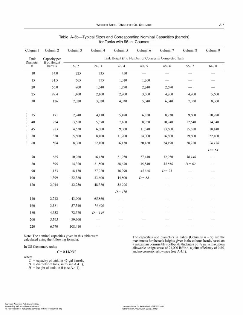
WELDED STEEL TANKS FOR OIL STORAGE A-7
Copyright AmericaProvided by IHS uNo reproduction o
Table A-3b—Typical Sizes and Corresponding Nominal Capacities (barrels)for Tanks with 96-in. Courses
Column 1 Column 2 Column 3 Column 4 Column 5 Column 6 Column 7 Column 8 Column 9
Tank Diameter
ft
Capacity per ft of Height
barrels
Tank Height (ft) / Number of Courses in Completed Tank
16 / 2 24 / 3 32 / 4 40 / 5 48 / 6 56 / 7 64 / 8
10 14.0 225 335 450 — — — —
15 31.5 505 755 1,010 1,260 — — —
20 56.0 900 1,340 1,790 2,240 2,690 — —
25 87.4 1,400 2,100 2,800 3,500 4,200 4,900 5,600
30 126 2,020 3,020 4,030 5,040 6,040 7,050 8,060
35 171 2,740 4,110 5,480 6,850 8,230 9,600 10,980
40 224 3,580 5,370 7,160 8,950 10,740 12,540 14,340
45 283 4,530 6,800 9,060 11,340 13,600 15,880 18,140
50 350 5,600 8,400 11,200 14,000 16,800 19,600 22,400
60 504 8,060 12,100 16,130 20,160 24,190 28,220 26,130
D = 54
70 685 10,960 16,450 21,950 27,440 32,930 30,140 —
80 895 14,320 21,500 28,670 35,840 35,810 D = 62 —
90 1,133 18,130 27,220 36,290 45,360 D = 73 — —
100 1,399 22,380 33,600 44,800 D = 88 — — —
120 2,014 32,250 48,380 54,200 — — — —
D = 110
140 2,742 43,900 65,860 — — — — —
160 3,581 57,340 74,600 — — — — —
180 4,532 72,570 D = 149 — — — — —
200 5,595 89,600 — — — — — —
220 6,770 108,410 — — — — — —
Note: The nominal capacities given in this table werecalculated using the following formula:
In US Customary units:C = 0.14D2H,
whereC = capacity of tank, in 42-gal barrels,D = diameter of tank, in ft (see A.4.1),H = height of tank, in ft (see A.4.1).
The capacities and diameters in italics (Columns 4 – 9) are themaximums for the tank heights given in the column heads, based ona maximum permissible shell-plate thickness of 1/2 in., a maximumallowable design stress of 21,000 lbf/in.2, a joint efficiency of 0.85,and no corrosion allowance (see A.4.1).
--``,,,,,,`,,`,`,`,``,,````,,``-`-`,,`,,`,`,,`---
n Petroleum Institute nder license with API Licensee=Bazan Oil Refineries Ltd/5957352001
Not for Resale, 02/18/2008 23:53:18 MSTr networking permitted without license from IHS
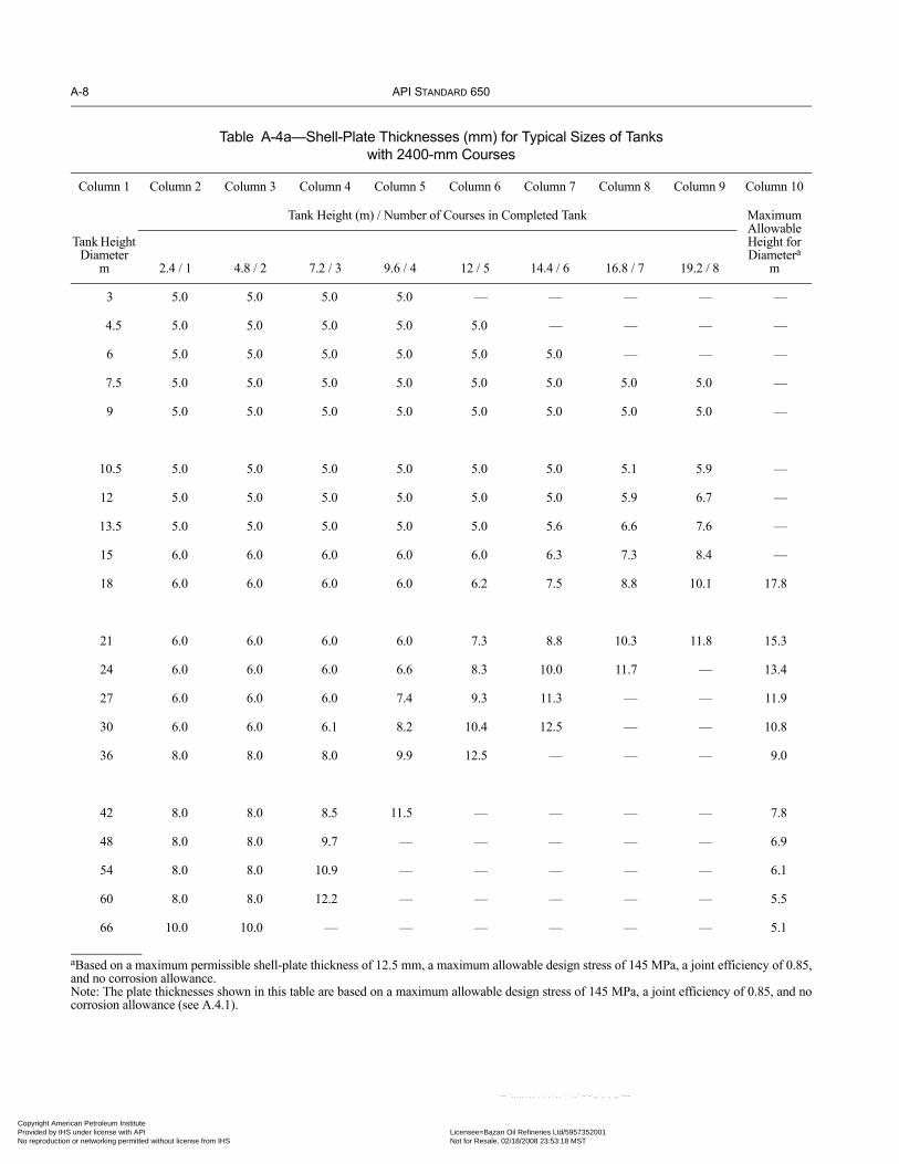
A-8 API STANDARD 650
Copyright AmProvided by No reproduc
Table A-4a—Shell-Plate Thicknesses (mm) for Typical Sizes of Tanks with 2400-mm Courses
Column 1 Column 2 Column 3 Column 4 Column 5 Column 6 Column 7 Column 8 Column 9 Column 10
Tank Height Diameter
m
Tank Height (m) / Number of Courses in Completed Tank Maximum Allowable Height for Diametera
m2.4 / 1 4.8 / 2 7.2 / 3 9.6 / 4 12 / 5 14.4 / 6 16.8 / 7 19.2 / 8
3 5.0 5.0 5.0 5.0 — — — — —
4.5 5.0 5.0 5.0 5.0 5.0 — — — —
6 5.0 5.0 5.0 5.0 5.0 5.0 — — —
7.5 5.0 5.0 5.0 5.0 5.0 5.0 5.0 5.0 —
9 5.0 5.0 5.0 5.0 5.0 5.0 5.0 5.0 —
10.5 5.0 5.0 5.0 5.0 5.0 5.0 5.1 5.9 —
12 5.0 5.0 5.0 5.0 5.0 5.0 5.9 6.7 —
13.5 5.0 5.0 5.0 5.0 5.0 5.6 6.6 7.6 —
15 6.0 6.0 6.0 6.0 6.0 6.3 7.3 8.4 —
18 6.0 6.0 6.0 6.0 6.2 7.5 8.8 10.1 17.8
21 6.0 6.0 6.0 6.0 7.3 8.8 10.3 11.8 15.3
24 6.0 6.0 6.0 6.6 8.3 10.0 11.7 — 13.4
27 6.0 6.0 6.0 7.4 9.3 11.3 — — 11.9
30 6.0 6.0 6.1 8.2 10.4 12.5 — — 10.8
36 8.0 8.0 8.0 9.9 12.5 — — — 9.0
42 8.0 8.0 8.5 11.5 — — — — 7.8
48 8.0 8.0 9.7 — — — — — 6.9
54 8.0 8.0 10.9 — — — — — 6.1
60 8.0 8.0 12.2 — — — — — 5.5
66 10.0 10.0 — — — — — — 5.1
aBased on a maximum permissible shell-plate thickness of 12.5 mm, a maximum allowable design stress of 145 MPa, a joint efficiency of 0.85,and no corrosion allowance.Note: The plate thicknesses shown in this table are based on a maximum allowable design stress of 145 MPa, a joint efficiency of 0.85, and nocorrosion allowance (see A.4.1).
--``,,,,,,`,,`,`,`,``,,````,,``-`-`,,`,,`,`,,`---
erican Petroleum Institute IHS under license with API Licensee=Bazan Oil Refineries Ltd/5957352001
Not for Resale, 02/18/2008 23:53:18 MSTtion or networking permitted without license from IHS

WELDED STEEL TANKS FOR OIL STORAGE A-9
Copyright AmericaProvided by IHS uNo reproduction o
Table A-4b—Shell-Plate Thicknesses (in.) for Typical Sizes of Tanks with 96-in. Courses
Column 1 Column 2 Column 3 Column 4 Column 5 Column 6 Column 7 Column 8 Column 9 Column 10
Tank Height Diameter
ft
Tank Height (ft) / Number of Courses in Completed Tank Maximum Allowable Height for Diametera
ft8 / 1 16 / 2 24 / 3 32 / 4 40 / 5 48 / 6 56 / 7 64 / 8
10 3/16 3/16 3/16 3/16 — — — — —
15 3/16 3/16 3/16 3/16 3/16 — — — —
20 3/16 3/16 3/16 3/16 3/16 3/16 — — —
25 3/16 3/16 3/16 3/16 3/16 3/16 0.20 0.23 —
30 3/16 3/16 3/16 3/16 3/16 0.21 0.24 0.28 —
35 3/16 3/16 3/16 3/16 0.20 0.24 0.28 0.33 —
40 3/16 3/16 3/16 3/16 0.23 0.28 0.32 0.37 —
45 3/16 3/16 3/16 0.21 0.26 0.31 0.36 0.42 —
50 1/4 1/4 1/4 0.25 0.29 0.35 0.40 0.46 —
60 1/4 1/4 1/4 0.27 0.34 0.41 0.48 — 58.2
70 1/4 1/4 1/4 0.32 0.40 0.48 — — 50.0
80 1/4 1/4 0.27 0.37 0.46 — — — 43.9
90 1/4 1/4 0.31 0.41 — — — — 39.1
100 1/4 1/4 0.34 0.46 — — — — 35.3
120 5/16 5/16 0.41 — — — — — 29.6
140 5/16 5/16 0.47 — — — — — 25.5
160 5/16 0.35 — — — — — — 22.5
180 5/16 0.40 — — — — — — 20.1
200 5/16 0.44 — — — — — — 18.2
220 3/8 0.48 — — — — — — 16.6
aBased on a maximum permissible shell-plate thickness of 1/2 in., a maximum allowable design stress of 21,000 lbf/in.2, a joint efficiency of0.85, and no corrosion allowance.Note: The plate thicknesses shown in this table are based on a maximum allowable design stress of 21,000 lbf/in.2, a joint efficiency of 0.85, andno corrosion allowance (see A.4.1).
--``,,,,,,`,,`,`,`,``,,````,,``-`-`,,`,,`,`,,`---
n Petroleum Institute nder license with API Licensee=Bazan Oil Refineries Ltd/5957352001
Not for Resale, 02/18/2008 23:53:18 MSTr networking permitted without license from IHS

A-10 API STANDARD 650
•
•
•
•
•
Copyright AmProvided by No reproduc
--``,,,,,,`,,`,`,`,``,,````,,``-`-`,,`,,`,`,,`---
A.4 Thickness of Shell PlatesA.4.1 The minimum thicknesses of shell plates shall be computed from the stress on the vertical joints, using the followingformula:
In SI units:
where
t = minimum thickness, in mm (see 5.6.1.1),
D = nominal diameter of the tank, in m (see 5.6.1.1, Note 1),
H = design liquid level, in m (see 5.6.3.2),
G = specific gravity of the liquid to be stored, as specified by the Purchaser. The specific gravity shall not be less than 1.0,
E = joint efficiency, which is either 0.85 or 0.70 (see A.3.4),
CA = corrosion allowance, in mm, as specified by the Purchaser (see 5.3.2).
In US Customary units:
where
t = minimum thickness (in.) (see 5.6.1.1),
D = nominal diameter of the tank (ft) (see 5.6.1.1, Note 1),
H = design liquid level (ft) (see 5.6.3.2),
G = specific gravity of the liquid to be stored, as specified by the Purchaser. The specific gravity shall not be less than 1.0,
E = joint efficiency, which is either 0.85 or 0.70 (see A.3.4),
CA = corrosion allowance (in.), as specified by the Purchaser (see 5.3.2).
A.4.2 The nominal thickness of shell plates (including shell extensions for floating roofs) shall not be less than that listed in3.6.1.1. The nominal thickness of shell plates refers to the tank shell as constructed. The nominal thicknesses given in 5.6.1.1 arebased on erection requirements.
A.5 Tank JointsA.5.1 Vertical and horizontal joints in the shell, bottom joints, shell-to-bottom joints, wind-girder joints, and roof and top-anglejoints shall conform to 5.1.5.
A.5.2 The requirements of 5.7.3 for the spacing of welds do not apply except for the requirement that the spacing between thetoes of welds around a connection shall not be less than 21/2 times the shell thickness at the connection.
A.5.3 When radiographic inspection is required (joint efficiency = 0.85), the spot radiographs of vertical joints shall conform to8.1.2.2, Item a only, excluding the 10 mm (3/8 in.) shell-thickness limitation in Item a and excluding the additional random spotradiograph required by Item a. The spot radiographs of horizontal joints shall conform to 8.1.2.3.
A.6 Intermediate Wind GirdersCalculations for and installation of intermediate wind girders are not required unless specified by the Purchaser.
t 4.9D H 0.3–( )GE( ) 145( )
--------------------------------------- CA+=
t 2.6D H 1–( )GE( ) 21,000( )
---------------------------------- CA+=
erican Petroleum Institute IHS under license with API Licensee=Bazan Oil Refineries Ltd/5957352001
Not for Resale, 02/18/2008 23:53:18 MSTtion or networking permitted without license from IHS

WELDED STEEL TANKS FOR OIL STORAGE A-11
•
• 07
Copyright AmericaProvided by IHS uNo reproduction o
A.7 Shell Manholes and NozzlesA.7.1 Except for other designs and shapes permitted by 5.7.1.2, shell manholes shall conform to 5.7.5, Figures 5-7A and 5-7B,and Tables 5-3 through 5-5.
A.7.2 Shell nozzles and flanges shall conform to 5.7.6; Figures 5-7B, 5-8, and 5-10; and Tables 5-6 through 5-8.
A.7.3 The radiographic requirements of 5.7.3.4 do not apply.
A.8 Flush-Type Cleanout FittingsA.8.1 The details and dimensions of flush-type cleanout fittings shall conform to 5.7.7, Figures 5-12 and 5-13, and Tables 5-9through 5-11.
A.8.2 The provisions for stress relief specified in 5.7.4 and 5.7.7.3 are not required unless they are specified by the Purchaser orunless any plate in the unit has a thickness greater than 16 mm (5/8 in.).
A.9 Flush-Type Shell ConnectionsA.9.1 The details and dimensions of flush-type shell connections shall conform to 5.7.8, Figure 5-14, and Table 5-12.
A.9.2 The provisions for stress relief specified in 5.7.4 and 5.7.8.3 are not required unless they are specified by the Purchaser orunless any plate in the assembly has a thickness greater than 16 mm (5/8 in.).
n Petroleum Institute nder license with API Licensee=Bazan Oil Refineries Ltd/5957352001
Not for Resale, 02/18/2008 23:53:18 MSTr networking permitted without license from IHS
--``,,,,,,`,,`,`,`,``,,````,,``-`-`,,`,,`,`,,`---

Copyright AmProvided by No reproduc
--``,,,,,
,`,,`,`,`,``,,````,,``-`-`,,`,,`,`,,`---erican Petroleum Institute IHS under license with API Licensee=Bazan Oil Refineries Ltd/5957352001
Not for Resale, 02/18/2008 23:53:18 MSTtion or networking permitted without license from IHS

Copyright AmericaProvided by IHS uNo reproduction o
--``,,,,,,`,,`,`,`,``,,````,,``-`-`,,`,,`,`,,`---
APPENDIX B—RECOMMENDATIONS FOR DESIGN AND CONSTRUCTION OF FOUNDATIONS FOR ABOVEGROUND OIL STORAGE TANKS
B.1 ScopeB.1.1 This appendix provides important considerations for the design and construction of foundations for aboveground steel oilstorage tanks with flat bottoms. Recommendations are offered to outline good practice and to point out some precautions thatshould be considered in the design and construction of storage tank foundations.
B.1.2 Since there is a wide variety of surface, subsurface, and climatic conditions, it is not practical to establish design data tocover all situations. The allowable soil loading and the exact type of subsurface construction to be used must be decided for eachindividual case after careful consideration. The same rules and precautions shall be used in selecting foundation sites as would beapplicable in designing and constructing foundations for other structures of comparable magnitude.
B.2 Subsurface Investigation and ConstructionB.2.1 At any tank site, the subsurface conditions must be known to estimate the soil bearing capacity and settlement that will beexperienced. This information is generally obtained from soil borings, load tests, sampling, laboratory testing, and analysis by anexperienced geotechnical engineer familiar with the history of similar structures in the vicinity. The subgrade must be capable ofsupporting the load of the tank and its contents. The total settlement must not strain connecting piping or produce gauging inaccu-racies, and the settlement should not continue to a point at which the tank bottom is below the surrounding ground surface. Theestimated settlement shall be within the acceptable tolerances for the tank shell and bottom.
B.2.2 When actual experience with similar tanks and foundations at a particular site is not available, the following ranges forfactors of safety should be considered for use in the foundation design criteria for determining the allowable soil bearing pres-sures. (The owner or geotechnical engineer responsible for the project may use factors of safety outside these ranges.)
a. From 2.0 to 3.0 against ultimate bearing failure for normal operating conditions.b. From 1.5 to 2.25 against ultimate bearing failure during hydrostatic testing.c. From 1.5 to 2.25 against ultimate bearing failure for operating conditions plus the maximum effect of wind or seismic loads.
B.2.3 Some of the many conditions that require special engineering consideration are as follows:
a. Sites on hillsides, where part of a tank may be on undisturbed ground or rock and part may be on fill or another construction orwhere the depth of required fill is variable.b. Sites on swampy or filled ground, where layers of muck or compressible vegetation are at or below the surface or where unsta-ble or corrosive materials may have been deposited as fill.c. Sites underlain by soils, such as layers of plastic clay or organic clays, that may support heavy loads temporarily but settleexcessively over long periods of time.d. Sites adjacent to water courses or deep excavations, where the lateral stability of the ground is questionable.e. Sites immediately adjacent to heavy structures that distribute some of their load to the subsoil under the tank sites, therebyreducing the subsoil’s capacity to carry additional loads without excessive settlement.f. Sites where tanks may be exposed to flood waters, possibly resulting in uplift, displacement, or scour.g. Sites in regions of high seismicity that may be susceptible to liquefaction.h. Sites with thin layers of soft clay soils that are directly beneath the tank bottom and that can cause lateral ground stabilityproblems.
B.2.4 If the subgrade is inadequate to carry the load of the filled tank without excessive settlement, shallow or superficial con-struction under the tank bottom will not improve the support conditions. One or more of the following general methods should beconsidered to improve the support conditions:
a. Removing the objectionable material and replacing it with suitable, compacted material.b. Compacting the soft material with short piles.c. Compacting the soft material by preloading the area with an overburden of soil. Strip or sand drains may be used in conjunc-tion with this method.d. Stabilizing the soft material by chemical methods or injection of cement grout.
B-1
n Petroleum Institute nder license with API Licensee=Bazan Oil Refineries Ltd/5957352001
Not for Resale, 02/18/2008 23:53:18 MSTr networking permitted without license from IHS
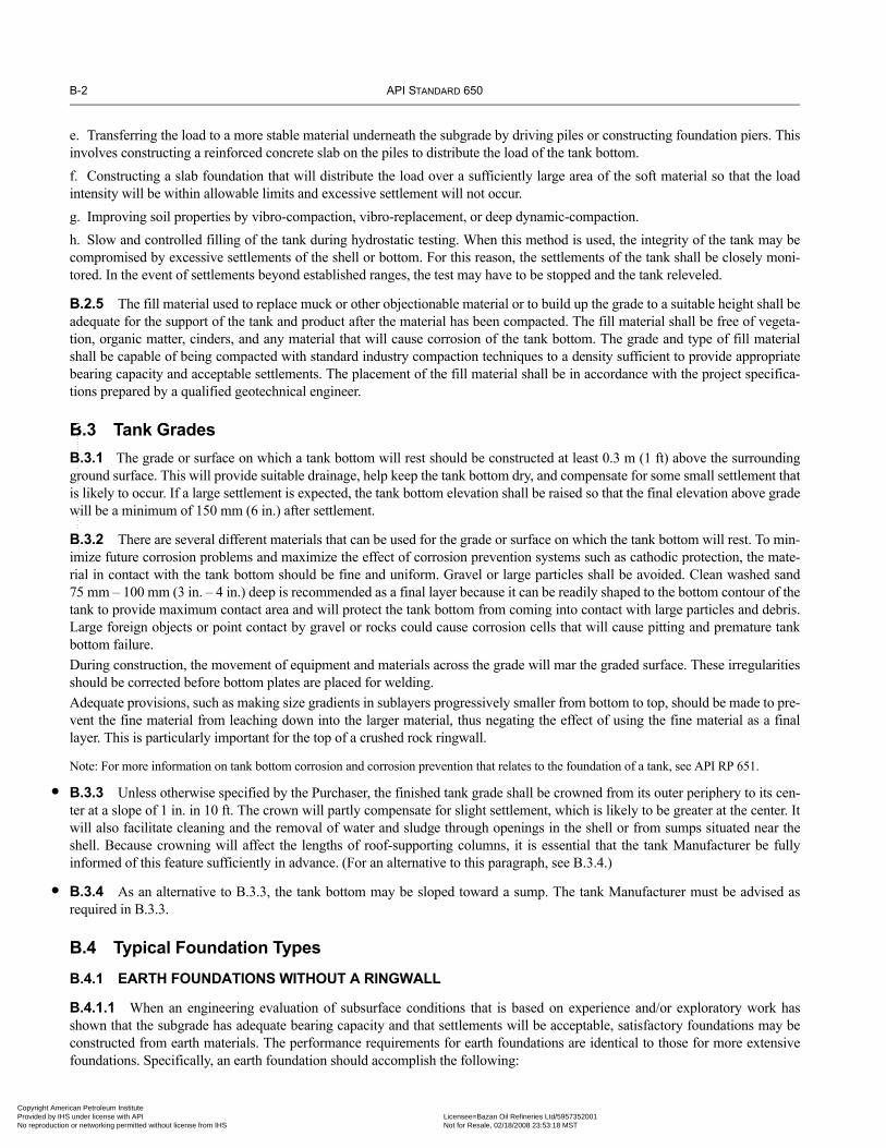
B-2 API STANDARD 650
•
•
Copyright AmProvided by No reproduc
e. Transferring the load to a more stable material underneath the subgrade by driving piles or constructing foundation piers. Thisinvolves constructing a reinforced concrete slab on the piles to distribute the load of the tank bottom.f. Constructing a slab foundation that will distribute the load over a sufficiently large area of the soft material so that the loadintensity will be within allowable limits and excessive settlement will not occur.g. Improving soil properties by vibro-compaction, vibro-replacement, or deep dynamic-compaction.h. Slow and controlled filling of the tank during hydrostatic testing. When this method is used, the integrity of the tank may becompromised by excessive settlements of the shell or bottom. For this reason, the settlements of the tank shall be closely moni-tored. In the event of settlements beyond established ranges, the test may have to be stopped and the tank releveled.
B.2.5 The fill material used to replace muck or other objectionable material or to build up the grade to a suitable height shall beadequate for the support of the tank and product after the material has been compacted. The fill material shall be free of vegeta-tion, organic matter, cinders, and any material that will cause corrosion of the tank bottom. The grade and type of fill materialshall be capable of being compacted with standard industry compaction techniques to a density sufficient to provide appropriatebearing capacity and acceptable settlements. The placement of the fill material shall be in accordance with the project specifica-tions prepared by a qualified geotechnical engineer.
B.3 Tank GradesB.3.1 The grade or surface on which a tank bottom will rest should be constructed at least 0.3 m (1 ft) above the surroundingground surface. This will provide suitable drainage, help keep the tank bottom dry, and compensate for some small settlement thatis likely to occur. If a large settlement is expected, the tank bottom elevation shall be raised so that the final elevation above gradewill be a minimum of 150 mm (6 in.) after settlement.
B.3.2 There are several different materials that can be used for the grade or surface on which the tank bottom will rest. To min-imize future corrosion problems and maximize the effect of corrosion prevention systems such as cathodic protection, the mate-rial in contact with the tank bottom should be fine and uniform. Gravel or large particles shall be avoided. Clean washed sand75 mm – 100 mm (3 in. – 4 in.) deep is recommended as a final layer because it can be readily shaped to the bottom contour of thetank to provide maximum contact area and will protect the tank bottom from coming into contact with large particles and debris.Large foreign objects or point contact by gravel or rocks could cause corrosion cells that will cause pitting and premature tankbottom failure.During construction, the movement of equipment and materials across the grade will mar the graded surface. These irregularitiesshould be corrected before bottom plates are placed for welding.Adequate provisions, such as making size gradients in sublayers progressively smaller from bottom to top, should be made to pre-vent the fine material from leaching down into the larger material, thus negating the effect of using the fine material as a finallayer. This is particularly important for the top of a crushed rock ringwall.
Note: For more information on tank bottom corrosion and corrosion prevention that relates to the foundation of a tank, see API RP 651.
B.3.3 Unless otherwise specified by the Purchaser, the finished tank grade shall be crowned from its outer periphery to its cen-ter at a slope of 1 in. in 10 ft. The crown will partly compensate for slight settlement, which is likely to be greater at the center. Itwill also facilitate cleaning and the removal of water and sludge through openings in the shell or from sumps situated near theshell. Because crowning will affect the lengths of roof-supporting columns, it is essential that the tank Manufacturer be fullyinformed of this feature sufficiently in advance. (For an alternative to this paragraph, see B.3.4.)
B.3.4 As an alternative to B.3.3, the tank bottom may be sloped toward a sump. The tank Manufacturer must be advised asrequired in B.3.3.
B.4 Typical Foundation TypesB.4.1 EARTH FOUNDATIONS WITHOUT A RINGWALL
B.4.1.1 When an engineering evaluation of subsurface conditions that is based on experience and/or exploratory work hasshown that the subgrade has adequate bearing capacity and that settlements will be acceptable, satisfactory foundations may beconstructed from earth materials. The performance requirements for earth foundations are identical to those for more extensivefoundations. Specifically, an earth foundation should accomplish the following:
--``,,,,,,`,,`,`,`,``,,````,,``-`-`,,`,,`,`,,`---
erican Petroleum Institute IHS under license with API Licensee=Bazan Oil Refineries Ltd/5957352001
Not for Resale, 02/18/2008 23:53:18 MSTtion or networking permitted without license from IHS
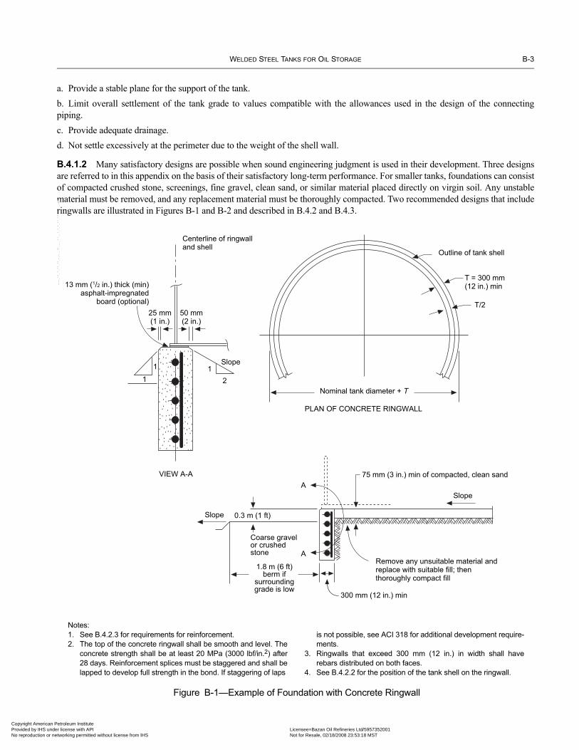
WELDED STEEL TANKS FOR OIL STORAGE B-3
Copyright AmericaProvided by IHS uNo reproduction o
a. Provide a stable plane for the support of the tank.b. Limit overall settlement of the tank grade to values compatible with the allowances used in the design of the connectingpiping.c. Provide adequate drainage.d. Not settle excessively at the perimeter due to the weight of the shell wall.
B.4.1.2 Many satisfactory designs are possible when sound engineering judgment is used in their development. Three designsare referred to in this appendix on the basis of their satisfactory long-term performance. For smaller tanks, foundations can consistof compacted crushed stone, screenings, fine gravel, clean sand, or similar material placed directly on virgin soil. Any unstablematerial must be removed, and any replacement material must be thoroughly compacted. Two recommended designs that includeringwalls are illustrated in Figures B-1 and B-2 and described in B.4.2 and B.4.3.
Figure B-1—Example of Foundation with Concrete Ringwall
Outline of tank shell
T = 300 mm(12 in.) min
T/2
Nominal tank diameter + T
PLAN OF CONCRETE RINGWALL
Centerline of ringwalland shell
13 mm (1/2 in.) thick (min)asphalt-impregnated
board (optional)
25 mm(1 in.)
50 mm(2 in.)
VIEW A-A
Slope
2
1
1
1
75 mm (3 in.) min of compacted, clean sand
Slope
Remove any unsuitable material andreplace with suitable fill; thenthoroughly compact fill
Coarse gravelor crushedstone
Slope
1.8 m (6 ft)berm if
surroundinggrade is low
0.3 m (1 ft)
A
A
300 mm (12 in.) min
Notes:1. See B.4.2.3 for requirements for reinforcement.2. The top of the concrete ringwall shall be smooth and level. The
concrete strength shall be at least 20 MPa (3000 lbf/in.2) after28 days. Reinforcement splices must be staggered and shall belapped to develop full strength in the bond. If staggering of laps
is not possible, see ACI 318 for additional development require-ments.
3. Ringwalls that exceed 300 mm (12 in.) in width shall haverebars distributed on both faces.
4. See B.4.2.2 for the position of the tank shell on the ringwall.
--``,,,,,,`,,`,`,`,``,,````,,``-`-`,,`,,`,`,,`---
n Petroleum Institute nder license with API Licensee=Bazan Oil Refineries Ltd/5957352001
Not for Resale, 02/18/2008 23:53:18 MSTr networking permitted without license from IHS

B-4 API STANDARD 650
Copyright AmProvided by No reproduc
B.4.2 EARTH FOUNDATIONS WITH A CONCRETE RINGWALL
B.4.2.1 Large tanks and tanks with heavy or tall shells and/or self-supported roofs impose a substantial load on the foundationunder the shell. This is particularly important with regard to shell distortion in floating-roof tanks. When there is some doubtwhether a foundation will be able to carry the shell load directly, a concrete ringwall foundation should be used. As an alternativeto the concrete ringwall noted in this section, a crushed stone ringwall (see B.4.3) may be used. A foundation with a concrete ring-wall has the following advantages:
a. It provides better distribution of the concentrated load of the shell to produce a more nearly uniform soil loading under the tank.b. It provides a level, solid starting plane for construction of the shell.c. It provides a better means of leveling the tank grade, and it is capable of preserving its contour during construction.d. It retains the fill under the tank bottom and prevents loss of material as a result of erosion.e. It minimizes moisture under the tank.
A disadvantage of concrete ringwalls is that they may not smoothly conform to differential settlements. This disadvantage maylead to high bending stresses in the bottom plates adjacent to the ringwall.
B.4.2.2 When a concrete ringwall is designed, it shall be proportioned so that the allowable soil bearing is not exceeded. Theringwall shall not be less than 300 mm (12 in.) thick. The centerline diameter of the ringwall should equal the nominal diameter ofthe tank; however, the ringwall centerline may vary if required to facilitate the placement of anchor bolts or to satisfy soil bearinglimits for seismic loads or excessive uplift forces. The depth of the wall will depend on local conditions, but the depth must besufficient to place the bottom of the ringwall below the anticipated frost penetration and within the specified bearing strata. As aminimum, the bottom of the ringwall, if founded on soil, shall be located 0.6 m (2 ft) below the lowest adjacent finish grade. Tankfoundations must be constructed within the tolerances specified in 7.5.5. Recesses shall be provided in the wall for flush-typecleanouts, drawoff sumps, and any other appurtenances that require recesses.
B.4.2.3 A ringwall should be reinforced against temperature changes and shrinkage and reinforced to resist the lateral pressureof the confined fill with its surcharge from product loads. ACI 318 is recommended for design stress values, material specifica-tions, and rebar development and cover. The following items concerning a ringwall shall be considered:
a. The ringwall shall be reinforced to resist the direct hoop tension resulting from the lateral earth pressure on the ringwall’s insideface. Unless substantiated by proper geotechnical analysis, the lateral earth pressure shall be assumed to be at least 50% of the verti-cal pressure due to fluid and soil weight. If a granular backfill is used, a lateral earth pressure coefficient of 30% may be used.b. The ringwall shall be reinforced to resist the bending moment resulting from the uniform moment load. The uniform momentload shall account for the eccentricities of the applied shell and pressure loads relative to the centroid of the resulting soil pressure.The pressure load is due to the fluid pressure on the horizontal projection of the ringwall inside the shell.c. The ringwall shall be reinforced to resist the bending and torsion moments resulting from lateral, wind, or seismic loadsapplied eccentrically to it. A rational analysis, which includes the effect of the foundation stiffness, shall be used to determinethese moments and soil pressure distributions.
Figure B-2—Example of Foundation with Crushed Stone Ringwall
75 mm (3 in.) min of compacted,
clean sand
Thoroughly compacted fill offine gravel, coarse sand,or other stable material
Slope top of ringwallaway from tank if
paved
0.9 m
(3 ft) min
1
1.5
Crushed stone or gravel1
1
0.6 m
(2 ft) min
Note: Any unsuitable material shall be removed and replaced with suitable fill; the fill shall then bethoroughly compacted.
erican Petroleum Institute IHS under license with API Licensee=Bazan Oil Refineries Ltd/5957352001
Not for Resale, 02/18/2008 23:53:18 MSTtion or networking permitted without license from IHS
--``,,,,,,`,,`,`,`,``,,````,,``-`-`,,`,,`,`,,`---

WELDED STEEL TANKS FOR OIL STORAGE B-5
•
Copyright AmericaProvided by IHS uNo reproduction o
--``,,,,,,`,,`,`,`,``,,````,,``-`-`,,`,,`,`,,`---
d. The total hoop steel area required to resist the loads noted above shall not be less than the area required for temperaturechanges and shrinkage. The hoop steel area required for temperature changes and shrinkage is 0.0025 times the vertical cross-sec-tional area of the ringwall or the minimum reinforcement for walls called for in ACI 318, Chapter 14.e. For ringwalls, the vertical steel area required for temperature changes and shrinkage is 0.0015 times the horizontal cross-sec-tional area of the ringwall or the minimum reinforcement for walls called for in ACI 318, Chapter 14. Additional vertical steelmay be required for uplift or torsional resistance. If the ring foundation is wider than its depth, the design shall consider its behav-ior as an annular slab with flexure in the radial direction. Temperature and shrinkage reinforcement shall meet the ACI 318provisions for slabs. (See ACI 318, Chapter 7.)f. When the ringwall width exceeds 460 mm (18 in.), using a footing beneath the wall should be considered. Footings may alsobe useful for resistance to uplift forces.g. Structural backfill within and adjacent to concrete ringwalls and around items such as vaults, undertank piping, and sumpsrequires close field control to maintain settlement tolerances. Backfill should be granular material compacted to the density andcompacting as specified in the foundation construction specifications. For other backfill materials, sufficient tests shall be con-ducted to verify that the material has adequate strength and will undergo minimal settlement.
B.4.3 EARTH FOUNDATIONS WITH A CRUSHED STONE AND GRAVEL RINGWALL
B.4.3.1 A crushed stone or gravel ringwall will provide adequate support for high loads imposed by a shell. A foundation witha crushed stone or gravel ringwall has the following advantages:
a. It provides better distribution of the concentrated load of the shell to produce a more nearly uniform soil loading under thetank.b. It provides a means of leveling the tank grade, and it is capable of preserving its contour during construction.c. It retains the fill under the tank bottom and prevents loss of material as a result of erosion.d. It can more smoothly accommodate differential settlement because of its flexibility.
A disadvantage of the crushed stone or gravel ringwall is that it is more difficult to construct it to close tolerances and achieve aflat, level plane for construction of the tank shell.
B.4.3.2 For crushed stone or gravel ringwalls, careful selection of design details is necessary to ensure satisfactory perfor-mance. The type of foundation suggested is shown in Figure B-2. Significant details include the following:
a. The 0.9 m (3 ft) shoulder and berm shall be protected from erosion by being constructed of crushed stone or covered with apermanent paving material.b. Care shall be taken during construction to prepare and maintain a smooth, level surface for the tank bottom plates.c. The tank grade shall be constructed to provide adequate drainage away from the tank foundation.d. The tank foundation must be true to the specified plane within the tolerances specified in 7.5.5.
B.4.4 SLAB FOUNDATIONS
B.4.4.1 When the soil bearing loads must be distributed over an area larger than the tank area or when it is specified by theowner, a reinforced concrete slab shall be used. Piles beneath the slab may be required for proper tank support.
B.4.4.2 The structural design of the slab, whether on grade or on piles, shall properly account for all loads imposed upon theslab by the tank. The reinforcement requirements and the design details of construction shall be in accordance with ACI 318.
B.5 Tank Foundations for Leak DetectionAppendix I provides recommendations on the construction of tank and foundation systems for the detection of leaks through thebottoms of storage tanks.
n Petroleum Institute nder license with API Licensee=Bazan Oil Refineries Ltd/5957352001
Not for Resale, 02/18/2008 23:53:18 MSTr networking permitted without license from IHS

Copyright AmProvided by No reproduc
--``,,,,,,`,,`,`,`,``,,````,,``-`-`,,`,,`,`,,`---
erican Petroleum Institute IHS under license with API Licensee=Bazan Oil Refineries Ltd/5957352001
Not for Resale, 02/18/2008 23:53:18 MSTtion or networking permitted without license from IHS

•
07
•
•07
•
Copyright AmericaProvided by IHS uNo reproduction o
APPENDIX C—EXTERNAL FLOATING ROOFS
C.1 ScopeC.1.1 This appendix provides minimum requirements that, unless otherwise qualified in the text, apply to single-deck pontoon-type and double-deck-type floating roofs. See Section 2 for the definition of these roof types. This appendix is intended to limitonly those factors that affect the safety and durability of the installation and that are considered to be consistent with the qualityand safety requirements of this Standard. Numerous alternative details and proprietary appurtenances are available; however,agreement between the Purchaser and the Manufacturer is required before they are used.
C.1.2 The type of roof and seal to be provided shall be as specified on the Data Sheet, Line 30. If the type is not specified, theManufacturer shall provide a roof and seal that is cost-effective and suitable for the specified service. Pan-type floating roofs shallnot be used.
C.1.3 The Purchaser is required to provide all applicable jurisdictional requirements that apply to external floating roofs (see1.3).
C.1.4 See Appendix W for bid requirements pertaining to external floating roofs.
C.2 MaterialThe material requirements of Section 4 shall apply unless otherwise stated in this appendix. Castings shall conform to any of thefollowing specifications:
a. ASTM A 27M, grade 405-205 (ASTM A 27, grade 60-30), fully annealed.b. ASTM A 27M, grade 450-240 (ASTM A 27, grade 65-35), fully annealed or normalized and tempered, or quenched andtempered.c. ASTM A 216M (ASTM A 216) WCA, WCB, or WCC grades annealed and normalized, or normalized and tempered.
C.3 DesignC.3.1 GENERAL
C.3.1.1 The roof and accessories shall be designed and constructed so that the roof is allowed to float to the maximum designliquid level and then return to a liquid level that floats the roof well below the top of the tank shell without damage to any part ofthe roof, tank, or appurtenances. During such an occurrence, no manual attention shall be required to protect the roof, tank, orappurtenances. If a windskirt or top-shell extension is used, it shall contain the roof seals at the highest point of travel. The Pur-chaser shall provide appropriate alarm devices to indicate a rise of the liquid in the tank to a level above the normal and overfillprotection levels (see NFPA 30 and API RP 2350). Overflow slots shall not be used as a primary means of detecting an overfillincident. If specified by the Purchaser (Table 4 of the Data Sheet), emergency overflow openings may be provided to protect thetank and floating roof from damage.
C.3.1.2 The application of corrosion allowances shall be a matter of agreement between the Purchaser and the Manufacturer.Corrosion allowance shall be added to the required minimum nominal thickness or, when no minimum nominal thickness isrequired, added to the minimum thickness required for functionality.
C.3.1.3 Sleeves and fittings that penetrate the single deck or lower decks of annular pontoons or lower decks of double-deckroofs, except for automatic bleeder vents, rim space vents, and leg sleeves, shall have a minimum wall thickness of “StandardWall” for pipe NPS 6 and larger and 6 mm (1/4 in.) for all other pipe and plate construction unless otherwise specified on the DataSheet, Table 5. Such penetrations shall extend into the liquid.
C.3.1.4 The annular space between the roof outer rim of the floating roof and the product side of the tank shell shall bedesigned for proper clearance of the peripheral seal (see C.3.13). All appurtenances and internal components of the tank shallhave adequate clearance for the proper operation of the completed roof assembly.
C.3.1.5 For tanks greater than 60 m (200 ft) in diameter, the deck portion of single-deck pontoon floating roofs shall bedesigned to avoid flexural fatigue failure caused by design wind loads. Such designs shall be a matter of agreement between thePurchaser and the Manufacturer, using techniques such as underside stitch welding.
C-1
n Petroleum Institute nder license with API Licensee=Bazan Oil Refineries Ltd/5957352001
Not for Resale, 02/18/2008 23:53:18 MSTr networking permitted without license from IHS
--``,,,,,,`,,`,`,`,``,,````,,``-`-`,,`,,`,`,,`---

C-2 API STANDARD 650
07
07
•
07
07
•
Copyright AmProvided by No reproduc
C.3.1.6 All conductive parts of the external floating roof shall be electrically interconnected and bonded to the outer tank struc-ture. Bonding (grounding) shunts shall be provided on the external floating roof and shall be located above the uppermost seal.Shunts shall be 50-mm (2-in.) wide by 28-gauge (0.4-mm [1/64-in.] thick) austenitic stainless steel as a minimum, or shall provideequivalent corrosion resistance and current carrying capacity as stated in NFPA 780 and API RP 2003. Shunt spacing shall be nomore than 3 m (10 ft). All movable cover accessories (hatches, manholes, pressure relief devices, and other openings) on the exter-nal floating roof shall be electrically bonded to the external floating roof to prevent static electricity sparking when they are opened.
C.3.2 JOINTS
C.3.2.1 Joints shall be designed as described in 5.1.
C.3.2.2 If the underside of the roof is to be coated, all coated joints shall be seal-welded.
C.3.3 DECKS
C.3.3.1 Roofs in corrosive service, such as covering sour crude oil, should be the contact type designed to eliminate the pres-ence of any air-vapor mixture under the deck.
C.3.3.2 Unless otherwise specified by the Purchaser, all deck plates shall have a minimum nominal thickness of 5 mm (3/16 in.)(permissible ordering basis—37.4 kg/m2, 7.65 lbf/ft2 of plate, 0.180-in. plate, or 7-gauge sheet).
C.3.3.3 Deck plates shall be joined by continuous full-fillet welds on the top side. On the bottom side, where flexure can beanticipated adjacent to girders, support legs, or other relatively rigid members, full-fillet welds not less than 50 mm (2 in.) long on250 mm (10 in.) centers shall be used on any plate laps that occur within 300 mm (12 in.) of any such members. A minimum ofthree fillet welds shall be made.
C.3.3.4 Top decks of double-deck roofs and of pontoon sections, which are designed with a permanent slope shall be designed,fabricated, and erected (with a minimum slope of 1 in 64) to minimize accumulation of standing water (e.g., pooling adjacent to arolling ladder’s track) when primary roof drains are open. This requirement is not intended to completely eliminate isolated pud-dles. When out of service, water shall flow freely to the primary roof drains. These decks shall preferably be lapped to provide thebest drainage. Plate buckles shall be kept to a minimum.
C.3.3.5 The deck of single-deck pontoon floating roofs shall be designed to be in contact with the liquid during normal opera-tion, regardless of service. The design shall accommodate deflection of the deck caused by trapped vapor.
C.3.3.6 All covers for roof openings, except roof drains and vents, shall have gaskets or other sealing surfaces and shall be pro-vided with a liquid-tight cover.
C.3.4 PONTOON DESIGN
C.3.4.1 Floating roofs shall have sufficient buoyancy to remain afloat on liquid with a specific gravity of the lower of the prod-uct specific gravity or 0.7 and with primary drains inoperative for the following conditions:
a. 250 mm (10 in.) of rainfall in a 24-hour period over the full horizontal tank area with the roofs intact. This condition does notapply to double-deck roofs provided with emergency drains designed to keep water to a lesser volume that the roofs will safelysupport. Such emergency drains shall not allow the product to flow onto the roof.
Note: The rainfall rate for sizing the roof drains in C.3.8 may result in a larger accumulated rainfall.
b. Single-deck and any two adjacent pontoon compartments punctured and flooded in single-deck pontoon roofs and any twoadjacent compartments punctured and flooded in double-deck roofs, both roof types with no water or live load.
With agreement by the Purchaser, Item b may be replaced by the following for floating roofs 6 m (20 ft) in diameter or less: Anyone compartment punctured and flooded in single-deck pontoon roofs or double-deck roofs, both roof types with no water or liveload.
C.3.4.2 The pontoon portions of single-deck pontoon-type roofs shall be designed to have adequate strength to prevent perma-nent distortion when the center deck is loaded by its design rainwater (C.3.4.1, Item a) or when the center deck and two adjacentpontoons are punctured (C.3.4.1, Item b). The allowable stress and stability criteria shall be jointly established by the Purchaserand the Manufacturer as part of the inquiry. Alternatively, a proof test simulating the conditions of C.3.4.1, with the roof floatingon water, may be performed on the roof or on one of similar design that is of equal or greater diameter.
•
erican Petroleum Institute IHS under license with API Licensee=Bazan Oil Refineries Ltd/5957352001
Not for Resale, 02/18/2008 23:53:18 MSTtion or networking permitted without license from IHS
--``,,,,,,`,,`,`,`,``,,````,,``-`-`,,`,,`,`,,`---

WELDED STEEL TANKS FOR OIL STORAGE C-3
•07
07
•
07
•
07
•
Copyright AmericaProvided by IHS uNo reproduction o
--``,,,,,,`,,`,`,`,``,,````,,``-`-`,,`,,`,`,,`---
C.3.4.3 Any penetration of the floating roof shall not allow product to flow onto the roof under design conditions.
C.3.5 PONTOON OPENINGS
Each compartment shall be provided with a liquid-tight manhole with a minimum nominal size of NPS 20. Manhole covers shallbe provided with suitable hold-down fixtures (which may be of the quick-opening type) or with other means of preventing windor fire-fighting hose streams from removing the covers. The top edge of the manhole necks shall be at an elevation that preventsliquid from entering the compartments under the conditions of C.3.4. With agreement by the Purchaser, floating roofs 6 m (20 ft)in diameter or less may be designed using a pontoon inspection port in place of a pontoon manhole.Each compartment shall be vented to protect against internal or external pressure. Vents may be in the manhole cover, inspectionport cover, or the top deck of the compartment. The vents shall be at an elevation that prevents liquid from entering the compart-ment under the conditions of C.3.4 and shall terminate in a manner that prevents entry of rain and fire-fighting liquids.
C.3.6 COMPARTMENTS
Compartment plates are radial or circumferential dividers forming compartments that provide flotation for the roof (see C.3.4).All internal compartment plates (or sheets) shall be single-fillet welded along all of their edges, and other welding shall be per-formed at junctions as required to make each compartment leak tight. Each compartment weld shall be tested for leak tightnessusing internal pressure or a vacuum box and a soap solution or penetrating oil.
C.3.7 LADDERS
Unless otherwise specified by the Purchaser, the floating roof shall be supplied with a ladder that automatically adjusts to any roofposition so that access to the roof is always provided. The ladder shall be designed for full-roof travel, regardless of the normalsetting of the roof-leg supports. The ladder shall have full-length handrails on both sides and shall be designed for a 4450 N(1000 lbf) midpoint load with the ladder in any operating position. Step assemblies shall be of open type and have non-slip walk-ing surfaces and self-leveling treads with a minimum width of 510 m (20 in.) and a 860 mm (34 in.) high handrail at the nose ofthe tread. When the roof is in its extreme low position, the slope of the rolling ladder shall not be less than 35 degrees to vertical,unless specified otherwise by the Purchaser. Wheels shall be provided at the lower end of the ladder, sized to prevent binding ofthe ladder, and provided with maintenance-free bearings. Ladders shall be grounded to both the roof and the gauger’s platformwith at least an AWG (American Wire Gage) 2/0 (67 sq. mm [0.104 sq. in.]), non-tangling cable. Cable shall be configured so thatit will not freeze to adjacent surfaces in cold weather. Ladder and track design shall minimize ponding by using trussed runwaysor other details considering fatigue and stiffening effects resulting from supports. The Purchaser may elect to add requirementssuch as a wider stair width, lateral roof loading, and alternate runway designs that reduce ponding under the ladder.
C.3.8 ROOF DRAINS
C.3.8.1 Primary Roof Drains
1. Primary roof drains shall be sized and positioned to accommodate the rainfall rates specified on the Data Sheet, Line 33,while preventing the roof from accumulating a water level greater than design, without allowing the roof to tilt excessively orinterfere with its operation. Roof drains shall be furnished attached to double-flanged, low-type nozzles on the tank shell withvalves to be supplied by the Purchaser. A swing-type check valve shall be provided at the inlet of drains unless otherwise spec-ified on the Data Sheet, Line 32. The drains shall be removable, if required by the Purchaser. Primary roof drains shall not besmaller than NPS 3 for roofs with a diameter less than or equal 36 m (120 ft) or smaller than NPS 4 for roofs with a diametergreater than 36 m (120 ft).
2. Primary roof drains shall be resistant to the tank’s contents, or suitably coated, and shall be free from floating, kinking, orcatching on any internal appurtenance or obstruction during operation, and from being crushed by landing legs on the bottom.
3. The Purchaser shall specify, on the Data Sheet, Line 32, the required primary roof drain. Acceptable types of primary roofdrains are:
a. Manufacturer’s standard drain,b. Steel swing or pivot-jointed pipe drains, designed and packed for external pressure,c. Stainless steel armored hose.
n Petroleum Institute nder license with API Licensee=Bazan Oil Refineries Ltd/5957352001
Not for Resale, 02/18/2008 23:53:18 MSTr networking permitted without license from IHS

C-4 API STANDARD 650
07
07
Copyright AmProvided by No reproduc
4. If supplied, rigid segments of drain piping attached to the bottom or the roof shall be guided, not rigidly attached, to allowfor differential thermal expansion and plate flexing. The design shall avoid being damaged by the roof support legs or otherobstructions.
5. Siphon-type and non-armored hose-type drains are not acceptable as primary roof drains.
6. Double-deck floating roofs up to 60 m (200 ft) in diameter shall have either a single center sump or a reversed-slope, top-center deck with multiple sumps connected to a single drain line, depending on the design rainfall quantity and the roof config-uration. Double-deck floating roofs larger than 60 m (200 ft) in diameter shall have a reversed-slope, top-center deck withmultiple roof sumps having individual drain lines.
7. Inlets to single-deck primary roof drains shall have guarded trash stops or screens to stop debris from entering and obstruct-ing the drain system. The Manufacturer shall provide isolation valves to stop product flow onto the roof when the check valvefails, unless specified otherwise on the Data Sheet, Line 32. Cut-off valves for this purpose shall have extension handles topermit actuation when puddles obstruct access to the valve.
8. When specified on the Data Sheet, Line 32, drains, sumps, check valves, and cut-off valves shall be protected from freezedamage by using special equipment designs. Any mechanically actuated cut-off valve shall permit actuation when the drainpipe is partially obstructed by chunk ice or slush (e.g., a ram valve or a metal-seated ball valve).
C.3.8.2 Emergency Roof Drains
Double-deck roofs shall have a minimum of three open-ended emergency roof drains designed to provide drainage to preventsinking the roof during severe rainfall events. Emergency drains are prohibited on single-deck floating roofs. Elevation of theemergency overflow drains shall be such that the outer rim cannot be completely submerged. These drains shall discharge atleast 300 mm (1 ft) below the bottom of the roof and shall consist of open-ended pipes, braced as necessary to the roof struc-ture. The drains shall be sized to handle the rainfall specified by the Purchaser, with a minimum diameter of NPS 4. The drainsshall be sealed with a slit fabric seal or similar device that covers at least 90% of the opening that will reduce the product-exposed surfaces while permitting rainwater passage. The drains shall be fabricated from Schedule 80 pipe, or heavier, and fit-tings with 6 mm (1/4-in.) thick roof deck reinforcing plates.
C.3.8.3 Out-of-Service Supplementary Drains
Threaded pipe couplings and plugs with a 600-mm (24-in.) extension “T-bar” handle shall be provided as supplementary drainswhen the roof is resting on its legs and when the primary drains are inoperative. The number of drains shall be based on the spec-ified rainfall rate (see Line 33 of the Data Sheet) and tank size. Fittings shall be at least NPS 4. Plugs shall have threads coatedwith a non-stick coating or anti-seize paste such as tetrafluoroethylene. One supplementary drain shall be located adjacent to theladder track.
C.3.9 VENTS
To prevent overstressing of the roof deck or seal membrane, automatic bleeder vents (vacuum breakers) shall be furnished forventing air to or from the underside of the deck when filling or emptying the tank. The Manufacturer shall determine and recom-mend the number and sizes of bleeder vents to be provided based on maximum filling and emptying rates specified. Each auto-matic bleeder vent (vacuum breaker vent) shall be closed at all times, except when required to be open to relieve excess pressureor vacuum, in accordance with the manufacturer’s design. Each automatic bleeder vent (vacuum breaker vent) shall be equippedwith a gasketed lid, pallet, flapper, or other closure device.
C.3.10 SUPPORTING LEGS
C.3.10.1 Floating roofs shall be provided with either removable or non-removable legs. If removable legs are specified on theData Sheet, Line 32, the legs shall be adjustable from the top side of the roof. and designed to be inserted through either fixed lowlegs or leg sleeves. Both low and high legs shall have cutouts (minimum of 19 mm [3/4 in.] wide) at the bottom to permit drainageof trapped product. Removable covers shall be provided for leg sleeves or fixed low legs when the adjustable legs are removed.Adjustable legs shall be capped on top. If specified on the Data Sheet, Line 32, removable legs shall be provided with storagerack(s) on the top of the pontoon or deck appropriate for leg storage during normal operation or during maintenance. Rack quan-tity and location shall be determined by the Manufacturer to balance the roof live load and shall take into account the weight ofthe rolling ladder. The materials of construction shall be tabulated on the Data Sheet, Table 5. Removable legs shall be no smaller
•
•
•
--``,,,,,,`,,`,`,`,``,,````,,``-`-`,,`,,`,`,,`---
erican Petroleum Institute IHS under license with API Licensee=Bazan Oil Refineries Ltd/5957352001
Not for Resale, 02/18/2008 23:53:18 MSTtion or networking permitted without license from IHS

WELDED STEEL TANKS FOR OIL STORAGE C-5
•
•07
•
•
07
07
Copyright AmericaProvided by IHS uNo reproduction o
than NPS 2. High legs shall have a stop to prevent their dropping through the low legs during installation. See C.1.3 regardingPurchaser specification of jurisdictional requirements.
C.3.10.2 The legs and attachments shall be designed to support the roof and a uniform live load of at least 1.2 kPa (25 lbf/ft2).Where possible, the roof load shall be transmitted to the legs through bulkheads or diaphragms. Leg attachments to single decksshall be given particular attention to prevent failures at the points of attachment.
C.3.10.3 Legs shall have settings for at least two levels:
a. A minimum setting determined by the Manufacturer to support the roof in the low-roof position while clearing mixers, noz-zles, shell manholes, seals, and other components inside the tank by at least 75 mm (3 in.), and
b. The minimum clearance of the roof in the high-roof position specified on the Data Sheet, Line 32.
When specified on the Data Sheet, Line 33, the two settings shall be field-adaptable to allow for uneven tank bottom settlement(i.e., constructed to permit small variations from the required positions for each leg).
C.3.10.4 Legs shall be Schedule 80 minimum and sleeves shall be Schedule 40 minimum unless specified otherwise on theData Sheet, Table 5.
C.3.10.5 Roof legs shall have matching steel landing pads continuous full-fillet welded to the tank bottom with minimumdimensions of 10-mm (3/8-in.) thickness by 350-mm (14-in.) diameter. The centerline of the legs shall coincide with the centerlineof the landing pads.
C.3.10.6 Roof support legs sleeves shall be installed plumb. Fixed legs or leg sleeves through single decks shall be reinforced.
C.3.10.7 All fixed leg or leg sleeve penetrations through the deck plate (top and bottom for pontoon and double-deck roofs)shall be attached to the deck plate(s) with continuous fillet welds made from the top side, as a minimum.
C.3.10.8 If specified (see C.1.3 regarding Purchaser specification of jurisdictional requirements), covers and seals shall be pro-vided at all openings.
C.3.10.9 When side entry mixers are specified and there is inadequate clearance between the roof and mixer components,rather than increasing the leg lengths, the pontoon (or double deck) shall be notched with a recessed pocket providing at least75 mm (3 in.) mixer component clearance at the low-roof position.
C.3.11 ROOF MANHOLES
Roof manholes shall be provided for access to the tank interior and for ventilation when the tank is empty. Manholes shall belocated around the roof to provide an effective pattern for access, lighting, and ventilation of the product storage interior. Eachmanhole shall have a minimum nominal diameter of 600 mm (24 in.) and shall have a liquid-tight gasketed, bolted cover equiva-lent to the cover shown in Figure 5-16.The minimum number of manholes shall be as follows:
C.3.12 CENTERING AND ANTI-ROTATION DEVICES
C.3.12.1 A guide pole shall be provided as an anti-rotation device for the floating roof. Locate the guide pole near the gauger’splatform. The guide pole shall be capable of resisting the lateral forces imposed by the roof ladder, unequal snow loads, and windloads.
C.3.12.2 Guide pole sections shall be welded with full penetration butt welds. Backing strips are not permitted. Provision mustbe made for draining and venting of unslotted pipe. See 7.5.2 for guide pole erection tolerance requirements.
Nominal Tank Diameter D,m (ft) Minimum Number
D ≤ 61 (200) 2
61 (200) < D ≤ 91 (300) 3
91 (300) < D 4
--``,,,,,,`,,`,`,`,``,,````,,``-`-`,,`,,`,`,,`---
n Petroleum Institute nder license with API Licensee=Bazan Oil Refineries Ltd/5957352001
Not for Resale, 02/18/2008 23:53:18 MSTr networking permitted without license from IHS

C-6 API STANDARD 650
•07
07
Copyright AmProvided by No reproduc
--``,,,,,,`,,`,`,`,``
C.3.12.3 The guide pole shall have all required emission control devices around the well opening where it penetrates the roof,such as those described in C.3.14.1, Item (1) and specified on the Data Sheet, Line 32. (See C.1.3 regarding Purchaser specifica-tion of jurisdictional requirement.)
C.3.13 PERIPHERAL SEALS
C.3.13.1 See H.4.4 for descriptions of peripheral seal types, selection guidelines, and additional requirements. Peripheral sealsare also referred to as rim seals.
C.3.13.2 The Purchaser shall specify the seal materials in the Data Sheet, Table 5.
C.3.13.3 See C.1.3 regarding Purchaser specification of jurisdictional requirements. All seals shall be installed such that gapsbetween the seal and the shell of the tank meet the gap requirements of the jurisdiction for new construction, if any, and the Pur-chaser’s gap requirements.
C.3.13.4 Installation and removal of peripheral seals shall not require draining the tank.
C.3.13.5 The specific requirements for external floating roof peripheral seals are:
Primary SealThe type of primary seal may be controlled by jurisdiction regulations. Types generally used are mechanical shoe seals and liquid-mounted (envelope) seals. Unless specified otherwise on the Data Sheet, Line 31, primary seals shall be the mechanical shoe typeand shall be supplied and installed by the roof Manufacturer.
Secondary SealThe type of secondary seal may be controlled by jurisdiction regulations. If required by the Purchaser, a secondary seal shall beprovided by the roof Manufacturer as specified on the Data Sheet, Line 31. Unless specified otherwise, secondary seals shall bethe wiper type and shall be supplied and installed by the roof Manufacturer. The design of the secondary seal shall permit inspec-tion of the primary seal without removal.
Mechanical Shoe SealsThe following additional requirements apply to mechanical shoe seals, if used, and which may be used as primary or secondaryseals:The metal band (shoe) is typically formed as a series of sheets that are overlapped or joined together to form a ring that is heldagainst the shell by a series of mechanical devices. For external floating roofs only, the mechanical shoe seal shoes shall extend atleast 610 mm (24 in.) above and at least 100 mm (4 in.) into the liquid at the design flotation level, except when this type of seal isthe secondary seal, installed above a primary seal. The “design flotation level” is defined as the roof position (under dead loadconditions) for the specific gravity range from 0.7 to the design specific gravity on the Data Sheet.
C.3.14 GAUGING DEVICE
C.3.14.1 Each roof shall be provided with gauging ports with caps (gauging wells or hatches) as indicated on the Data Sheet,Line 32 (see C.1.3 regarding Purchaser specification of jurisdictional requirement), with one port located adjacent to the gauger’splatform and remote from regions of turbulent flow. These ports may be as follows:
1. Slotted guide pole gauge wells: These are vertical anti-rotation pipes that can be used for gauging. Unless specified other-wise by the Purchaser, the pipe shall have two rows of 25-mm by 300-mm (1-in. by 12-in.) vertical slots on staggered 280-mm(11-in.) centers located 180 degrees apart. Slots shall range from the maximum fill height to near the tank bottom. Holes maybe provided in lieu of slots if holes are required by the Purchaser. Well and pole shall be equipped with all required emissioncontrol devices, which may include items such as a gasketed sliding well cover, and a pole wiper, as well as either a polesleeve or a pole float and float wiper (see API MPMS 19.2 for requirements and illustrations of some of these devices). If thereare no slots or holes located so as to allow the stored liquid to flow into the pole at liquid levels above the lowest operatinglevel, then the pole is not considered slotted for purposes of air regulation compliance (even if there are slots or holes locatedbelow the lowest operating level).2. Non-guide pole gauge wells: These shall be NPS 8 pipes projecting at least 150 mm (6 in.) above the roof’s outer rim. Forsample hatches without gauging apparatus, see C.3.15.3.
C.3.14.2 Each gauge well shall have a B16.5 Class 150 bolt pattern, flat-face pipe flange with a full-face gasket at its top, andshall be attached to a non-sparking cap. See C.1.3 regarding Purchaser specification of jurisdictional requirements.
•
••
•
•
•
•
,,````,,``-`-`,,`,,`,`,,`---
erican Petroleum Institute IHS under license with API Licensee=Bazan Oil Refineries Ltd/5957352001
Not for Resale, 02/18/2008 23:53:18 MSTtion or networking permitted without license from IHS

WELDED STEEL TANKS FOR OIL STORAGE C-7
•
•
•
•
07
•
•
•
Copyright AmericaProvided by IHS uNo reproduction o
C.3.14.3 Each gauge well shall have a permanent gauge mark or tab just inside the cap on the pipe wall called a “referencepoint” or “knife edge.”
C.3.14.4 When specified on the Data Sheet, Line 32, a datum plate shall be attached to the bottom of the slotted guide pole atthe distance designated by the Purchaser.
C.3.14.5 If striking plates are specified on the Data Sheet, Line 32, they shall be provided on the tank bottom beneath the guidepole or under the gauge well if no guide pole is specified.
C.3.14.6 A gauger’s platform shall be located at an elevation that remains above and clear of the roof, its sealing system, andfoam dam even during an overflow event. The Purchaser shall specify the platform location on the Data Sheet Plan. The directionis typically upwind of the direction of the prevailing wind.
C.3.15 OTHER ROOF ACCESSORIES
C.3.15.1 Wax Scrapers
If wax scrapers are specified on the Data Sheet, Line 31, they shall be located such that the scraping action occurs below the liquidsurface. Design of wax scrapers shall not interfere with bottom shell course accessories.
C.3.15.2 Foam Dams
A foam dam, if specified on the Data Sheet, Line 32, shall be installed on top plates of pontoon or roof deck at least 300 mm(12 in.) but no more than 600 mm (24 in.) from the tank shell to contain foam fire-fighting solution. The foam dam shall be a min-imum of 300 mm (12 in.) high and extend at least 50 mm (2 in.) above the lower of the secondary seal or any burnout panel, mea-sured at its highest contact point with the shell. The dam shall be fabricated from 10 gauge (0.134 in.) or thicker steel plate withsupport braces installed on the side of the foam dam closest to the center of the tank at a circumferential spacing of approximately1.5 m (5 ft) on center. Bottom of plate shall have 10-mm (3/8-in.) slotted weep holes. The dam shall be attached to the top deckplate by a continuous fillet weld on the foam side. See NFPA 11 for additional information regarding foam dams.
C.3.15.3 Sample Hatches
If specified on the Data Sheet, Line 32, the Manufacturer shall install an NPS 8 sample hatch with funnel on the roof deck withremote access from the gauging platform. Manufacturer shall install a recoil reel on the gauging platform. The hatch shall beequipped with a self-closing liquid-tight cover that can be opened and closed from the gauger’s platform.
C.3.15.4 Automatic Level Gauge
a. Tanks shall have a ground-level reading, automatic float-level gauge, unless otherwise specified on the Data Sheet, Table 4.b. Access for maintenance and repair shall be considered.c. Level gauge shall be located such that the float well is away from any appurtenances that produce turbulence.d. The bottom of the float well shall be approximately 150 mm (6 in.) above the tank bottom when the floating roof is at its low-est position.e. Gauge float wells shall be equipped with a gasketed cover that is bolted closed. See C.1.3 regarding Purchaser specification ofjurisdictional requirements.
C.3.15.5 Side Entry Mixers
a. Mixers shall conform to the Data Sheet, Line 26.b. Each mixer shall be installed in cover plates in dedicated shell nozzles or manholes.
C.4 Fabrication, Erection, Welding, Inspection, and TestingC.4.1 The applicable fabrication, erection, welding, inspection, and testing requirements of this Standard shall apply.
C.4.2 Deck seams and other joints that are required to be liquid- or vapor-tight shall be tested for leaks by means of penetratingoil or any other method consistent with the methods described in this Standard for testing cone-roof seams and tank-bottomseams.
--``,,,,,,`,,`,`,`,``,,````,,``-`-`,,`,,`,`,,`---
n Petroleum Institute nder license with API Licensee=Bazan Oil Refineries Ltd/5957352001
Not for Resale, 02/18/2008 23:53:18 MSTr networking permitted without license from IHS

C-8 API STANDARD 650
Copyright AmProvided by No reproduc
C.4.3 The roof shall be given a flotation test while the tank is being filled with water and emptied. During this test, the upperside of the lower deck shall be examined for leaks. The appearance of a damp spot on the upper side of the lower deck shall beconsidered evidence of leakage.
C.4.4 The upper side of the upper decks of pontoon and double-deck roofs shall be visually inspected for pinholes and defec-tive welding.
C.4.5 Drainpipe and hose systems of primary drains shall be tested with water at a pressure of 350 kPa (50 lbf/in.2) gauge. Dur-ing the flotation test, the roof drain valves shall be kept open and observed for leakage of the tank contents into the drain lines.
erican Petroleum Institute IHS under license with API Licensee=Bazan Oil Refineries Ltd/5957352001
Not for Resale, 02/18/2008 23:53:18 MSTtion or networking permitted without license from IHS
--``,,,,,,`,,`,`,`,``,,````,,``-`-`,,`,,`,`,,`---

07
07
07
Copyright AmericaProvided by IHS uNo reproduction o
APPENDIX D—TECHNICAL INQUIRIES
D.1 IntroductionAPI will consider written requests for interpretations of API Std 650. API staff will make such interpretations in writing after con-sulting, if necessary, with the appropriate committee officers and committee members. The API committee responsible for main-taining API Std 650 meets regularly to consider written requests for interpretations and revisions and to develop new criteriadictated by technological development. The committee’s activities in this regard are limited strictly to interpretations of the Stdand to the consideration of revisions to the present standard on the basis of new data or technology. As a matter of policy, APIdoes not approve, certify, rate, or endorse any item, construction, proprietary device, or activity, and accordingly, inquiries thatrequire such consideration will be returned. Moreover, API does not act as a consultant on specific engineering problems or on thegeneral understanding or application of the Standard. If, based on the inquiry information submitted, it is the opinion of the com-mittee that the inquirer should seek other assistance, the inquiry will be returned with the recommendation that such assistance beobtained. All inquiries that cannot be understood because they lack information will be returned.
D.2 Inquiry FormatD.2.1 Inquiries shall be limited strictly to requests for interpretation of the current standard or to the consideration of revisionsto the standard on the basis of new data or technology. Inquiries shall be submitted in the format described in D.2.2 through D.2.5.
D.2.2 The scope of an inquiry shall be limited to a single subject or a group of closely related subjects. An inquiry concerningtwo or more unrelated subjects will be returned.
D.2.3 An inquiry shall start with a background section that states the purpose of the inquiry, which would be either to obtain aninterpretation of the Standard or to propose a revision to the Standard. The background section shall concisely provide the infor-mation needed for the committee’s understanding of the inquiry (with sketches as necessary) and shall cite the applicable edition,revision, paragraphs, figures, and tables.
D.2.4 After the background section, an inquiry’s main section shall state the inquiry as a condensed, precise question, omittingsuperfluous background information and, where appropriate, posing the question so that the reply could take the form of “yes” or“no” (perhaps with provisos). This inquiry statement should be technically and editorially correct. The inquirer shall state what heor she believes the Standard requires. If the inquirer believes a revision to the Standard is needed, he or she shall provide recom-mended wording.
D.2.5 The inquirer shall include his or her name and mailing address. The inquiry should be typed; however, legible handwrit-ten inquiries will be considered. Inquiries should be submitted to the general manager of the Downstream Segment, AmericanPetroleum Institute, 1220 L Street, N.W., Washington, D.C. 20005. Inquiries complying with the above format may be submittedby electronic mail to: [email protected].
D.3 Technical Inquiry ResponsesFollowing are selected responses to requests for interpretation API Std 650 requirements. A more extensive listing of interpreta-tions can be found on the API website at www.api.org in the “Committees/Standards” section. The current version of API Std 650may differ from the following inquiries, which were developed against prior editions/addenda, making the following inquiriespossibly invalid. The paragraph references in the following have not been revised to the reflect the new paragraph numberingissued in the 11th Edition of API Std 650.
--``,,,,,,`,,`,`,`,``,,````,,``-`-`,,`,,`,`,,`---
D-1
n Petroleum Institute nder license with API Licensee=Bazan Oil Refineries Ltd/5957352001
Not for Resale, 02/18/2008 23:53:18 MSTr networking permitted without license from IHS

D-2 API STANDARD 650
07
07
Copyright AmProvided by No reproduc
SECTION 1.1 SCOPE
650-I-03/00 (Note: See 1.1.3 in the 11th Edition for revised rules pertaining to the use of SI units within the Standard.])
Question 1: Regarding the use of SI units, does API 650 allow either of the following?
(1) Use of SI units throughout the design process.
(2) Use the original U.S. Customary units with a hard conversion to SI units as a final step to the designprocess.
Reply 1: Yes, both are allowed.
Question 2: When SI units are used, does API 650 require different dimensional details compared to previous API 650 Edi-tions or USC unit details now specified in the 10th Edition?
Reply 2: The committee currently has an agenda item to study this question. Any changes resulting from this agenda itemwill appear in a future addendum or edition to API 650.
Question 3: When SI units are used, does API 650 require material thickness, material properties, configurations, etc. basedsolely on the SI units for a particular tank?
Reply 3: The committee currently has an agenda item to study this question. Any changes resulting from this agenda itemwill appear in a future addendum or edition to API 650.
Question 4: Does the wording of the Foreword to API 650 require a separate check of the USC results when SI unit are spec-ified and after making such a check using the USC results if more restrictive?
Reply 4: No.
SECTION 2.2 PLATES
650-I-09/01
Question: For plate material certified by the Manufacturer to meet more than one specification, such as A 516 Grade 60and A 516 Grade 70, which specification should be used when applying the rules in Table 2-3, Figure 2-1, andSection 2.2.9 of API 650?
Reply: Dual certification of material is not addressed in API 650, except in 2.1.4 and Appendix S.
650-I-11/01
Question: Does API 650 require that the material in the bottom shell course and the annular plate be the same materialspecification?
Reply: API 650, Section 2.2.9.1, requires bottom plates welded to the shell to comply with Figure 2-1, but does notrequire the bottom shell course and annular plate to be the same material specification.
650-I-33/03
Question: Are roof materials required to meet the toughness requirements in 2.2.9?
Reply: No. Refer to 2.2.9.1.
650-I-06/04
Question 1: Does the 0.01 in. thickness tolerance specified for plate in API 650, 2.2.1.2.3 apply to carbon and stainless coilproduct?
Reply 1: Yes. All requirements of the base document apply to an Appendix S tank unless specifically changed or waivedby a statement in Appendix S. Refer to S.1.5.
Question 2: When purchasing hot-rolled coil-processed steel for use as roof, shell, and/or bottom plate on a stainless tank,does the ASTM under-run tolerance apply?
Reply 2: The minimum of the ASTM tolerance or as specified in API 650, Sections 2.2.1.1, 2.2.1.2, or 2.2.1.3, shall apply.--``,,,,,,`,,`,`,`,``,,````,,``-`-`,,`,,`,`,,`---
erican Petroleum Institute IHS under license with API Licensee=Bazan Oil Refineries Ltd/5957352001
Not for Resale, 02/18/2008 23:53:18 MSTtion or networking permitted without license from IHS

WELDED STEEL TANKS FOR OIL STORAGE D-3
07
Copyright AmericaProvided by IHS uNo reproduction o
SECTION 2.5 PIPING AND FORGINGS
650-I-15/00
Question: 1 For nozzles made from pipe materials, does API 650, Section 2.5.2 require that seamless pipe be used for noz-zles in shells made from Group I, II, III, or IIIA materials?
Reply 1: Yes, unless ASTM A 671 pipe is used.
Question: 2: Does API 650, Section. 2.5.2 preclude the use of electric-resistance welded pipe meeting ASTM A 53, or elec-tric-welded pipe meeting API 5L, for nozzles in shells made from Group IV, IVA, V, or VI materials, but allowuse of electric-fusion-welded pipe nozzles made from ASTM A 671?
Reply 2: Yes.
SECTION 3.1 JOINTS
650-I-11/02
Question: Is there any allowance or provision to omit the top angle as required by API 650, 3.1.5.9e and 3.1.5.9f if we canshow by calculation that the top compression area is sufficient.
Reply: No.
650-I-32/02Question: Referring to API 650, Section 3.1.5.3b, does the phrase “…horizontal joints shall have a common vertical cen-
terline” mean that the mid-thickness of the plates align vertically?Reply: Yes. This is sometimes referred to as “centerline-stacked”.
650-I-40/02Question: Does the lap weld of two bottom plates on the butt-welded annular plates have to be 12 in. away from the annular
plates butt welds?Reply: No
650-I-37/03Question: Is it the intent of 3.1.3.5 to limit the maximum lap of a double welded lap joint to 2 in. and a single welded lap
joint to 1 in. If not, is there a maximum lap requirement for single welded lap joint bottoms and roofs? Wouldthis constraint, if any, also apply to bottom or roof repair or replacements governed by API 653.
Reply: No
650-I-49/03Question 1: Section 3.1.3.5 of API 650 specifies minimum lap joint dimensions. Is there any limit on the maximum width of
a lap joint?Reply 1: API Standard 650 does not address maximum lap.Question 2: Can a lap joint consisting of two (2) 1/4 in. plates be lapped 3 in.?Reply 2: Yes. Any lap that exceeds the minimum is acceptable. Refer to 3.1.3.5.
SECTION 3.5 ANNULAR BOTTOM PLATES
650-I-49/00
Question: If a tank bottom slopes downward toward the center of the tank, are the annular plates required to lap over thebottom plates?
Reply: This is not covered by API 650. (5.1.5.4 in the 11th Edition covers this issue.)
--``,,,,,,`,,`,`,`,``,,````,,``-`-`,,`,,`,`,,`---
n Petroleum Institute nder license with API Licensee=Bazan Oil Refineries Ltd/5957352001
Not for Resale, 02/18/2008 23:53:18 MSTr networking permitted without license from IHS

D-4 API STANDARD 650
Copyright AmProvided by No reproduc
650-I-22/03Question: Section 3.5.2 states the annular bottom plates shall have at least a 50 mm projection outside the shell. Is the ref-
erence point to calculate the projection located on the outside or inside diameter of the shell?Reply: The reference point is on the outside diameter of the shell plate, as stated in 3.5.2.
SECTION 3.6 SHELL DESIGN
650-I-02/02
Background: On one recent contract, corrosion allowance of 0.25 in. was specified only on first shell course. The tank is 250 ft(diameter) by 53 ft high, with a liquid height of 48 ft 0 in. (external floater) and design specific gravity = 0.968.Detail design per the current edition shows that the second course thickness is controlled by hydrostatic test con-dition, which is incorrect. Investigation has proven that the current rules in API 650 for the variable design pointmethod are not valid for variable corrosion allowance. The second course thickness calculated is more than theone-foot method will calculate, however, this is not stated in API 650. It is not unusual for a customer to specifyvariable corrosion allowance. The variable design point method is used only for large tanks and in some cases, asI have discovered, the second course will be calculated 1/16 in. thicker than needs to be when corrosion allow-ance is a significant percentage of first course. This extra thickness amounts to good some of money.
Question: Is the variable design point method of shell design covered under API 650, Section 3.6.4 valid for tanks withvariable corrosion allowance (i.e., different corrosion for each shell course)?
Reply: No.
SECTION 3.7 SHELL OPENINGS
650-I-33/99
Question: Referring to API 650, Section 3.7.4, must all flush-type cleanouts and flush-type shell connections be stress-relieved regardless of the material used, the nozzle diameter, or the thickness of the shell insert plate?
Reply: Yes, see Section 3.7.4.1.
650-I-53/99
Question 1: Per Section 3.7.4.2, for shell openings over NPS 12, if insert plates are not used to reinforce the shell opening, isthe shell thickness a factor in determining if PWHT of the assembly is required?
Reply 1: Yes.
Question 2: Regarding Section 3.7.4.2, is stress-relieving mandatory for the prefabricated assembly when the thickness of thethickened insert plate exceeds 1 in., irrespective of the shell opening size?
Reply 2: No. The requirement applies only to NPS 12 or larger connections.
650-I-01/00
Question: Does API 650, Section 3.7.4.3, allow stress-relieving nozzles, as described therein, after installation in the shell,using locally applied heaters?
Reply: No. The heat treatment must be performed prior to installation in the tank.
650-I-18/00
Question 1: Referencing Figure 3-14, does API 650 cover flush shell connections to be installed non-radially?
Reply 1: No.
Question 2: Referencing Figure 3-15, are flush-type shell connections smaller than 8 in. covered in API 650?
Reply 2: No.
erican Petroleum Institute IHS under license with API Licensee=Bazan Oil Refineries Ltd/5957352001
Not for Resale, 02/18/2008 23:53:18 MSTtion or networking permitted without license from IHS
--``,,,,,,`,,`,`,`,``,,````,,``-`-`,,`,,`,`,,`---

WELDED STEEL TANKS FOR OIL STORAGE D-5
Copyright AmericaProvided by IHS uNo reproduction o
650-I-20/00
Question: Does API 650, Section 3.7.4, require that all flush-type cleanout fittings be stress-relieved?
Reply: Yes, except as permitted by A.8.2.
650-I-32/00
Question: Are square or rectangular manways allowed per API 650? If no, what specific section limits them?
Reply: Yes. See Figure 3-14 for roof manway requirements.
650-I-34/00
Question: Does API 650, Section 3.7.4.2 require stress-relieving for materials in opening connections coming under GroupI, II, III or III A, when the thickness of the shell is less than 1 in., but the sum of the shell plate thickness and thereinforcement plate thickness exceeds 1 in. for NPS 12 and larger?
Reply: No.
650-I-43/00
Question: Referring to API 650, Section 3.7.4.2, must a prefabricated manhole assembly be stress relieved if the material isGroup II (A 131, Grade B), the shell plate is 3/8 in. thick, and the opening is a 24-in. diameter manhole?
Reply: No, because the shell is less than 1 in. thick.
650-I-47/00
Question: Does API 650, Section 3.7.6.1, permit making a hot tapping connection on a blind flange on a nozzle in a tank?
Reply: No. Refer to API 650, Section 3.8.3, for rules on installing a nozzle in a cover plate in a new tank. Refer to API653, Section 7.14, for rules and guidance on hot tapping in an in-service tank.
650-I-48/00
Question: Does API 650 define a “neck” as piping or nozzle passing through the shell of the tank to the first flange, regard-less of the length and configuration (such as an upturned pipe connected by an elbow and another short piecepipe to the first flange) of this pipe?
Reply: No. API does not define this term. Also, refer to Section 1.2, which defines the limits of applicability on piping.
650-I-07/02
Question: Given a 2 in. nominal bore non-reinforced nozzle in a non stress-relieved shell greater than 0.5 in. thickness. Arethe minimum distances for: (1) the outer edge of nozzle attachment weld to center line of a shell butt weld, eithervertical or horizontal, and (2) the toe-to-toe distance of the fillet to the shell-to-bottom weld, required to be 10 in.(or 8x weld thickness) and 3 in., respectively?
Reply: Yes, for new tanks, see API 650, sections 3.7.3.1, 3.7.3.3, and Figure 3-22.
650-I-28/02
Question: When stress relieving the assembly defined in API 650 Sections 3.7.4.1, 3.7.4.2, and 3.7.4.3, is it permissible toperform a local heat treatment that includes part of a shell plate, instead of the whole shell plate, i.e., the portionaround the connection at full width of shell plate?
Reply: No, however, there is no rule against shortening the plate length circumferentially, prior to installation of the fit-ting or connection.
650-I-56/02
Question: Do the minimum thicknesses listed in Table 3-10, and calculated by the equations in section 3.7.7.6 have a corro-sion allowance?
n Petroleum Institute nder license with API Licensee=Bazan Oil Refineries Ltd/5957352001
Not for Resale, 02/18/2008 23:53:18 MSTr networking permitted without license from IHS
--``,,,,,,`,,`,`,`,``,,````,,``-`-`,,`,,`,`,,`---

D-6 API STANDARD 650
Copyright AmProvided by No reproduc
Reply: No. See Section 3.3.2.
650-I-07/04Question: Regarding Section 3.7.2 as it applies to Appendix F, when calculating the required shell thickness at the nozzle
location is it necessary to use the joint efficiency factor that was used for calculating the required tank shellthickness?
Reply: No.
650-I-09/04Question 1: Section 3.7.1.8 states “Reinforcement of shell openings that comply with API Standard 620 are acceptable alter-
natives.” When using API 620 to calculate nozzle reinforcement does the entire API 620 standard apply?Reply 1: No.Question 2: API 620 limits the design temperature to 250ºF. Can the rules for nozzle reinforcement be used for designing
nozzle reinforcement for an API 650 Appendix M tank with a design temperature greater than 250ºF?Reply 2: Yes.Question 3: Can the rules for nozzle reinforcement in API 620 be used for designing nozzle reinforcement for a stainless
steel API 650 Appendix S tank?Reply 3: Yes.Question 4: When designing nozzle reinforcement for an API 650 tank using the rules of API 620, should the allowable
stresses of API 650 be used?Reply 4: Yes.
SECTION 3.8 SHELL ATTACHMENTS AND TANK APPURTENANCES
650-I-51/00Question: API 650, Section 3.8.3.2, requires mixer manway bolting flanges to be 40% thicker than the values shown in
Table 3-3. Footnote b under Table 3-4 requires the minimum manway neck thickness to be the lesser of theflange thickness or the shell plate. Is it therefore required that the minimum neck thickness on a mixer manwaybe the lesser of 140% of the flange thickness value in Table 3-3 or the shell thickness?
Reply: No.
650-I-53/00Question: Referring to API 650, is magnetic particle testing applicable for inspecting permanent attachments to the shell
and at temporary attachment removal areas, when the material group is of Group I (A 283, Grade C)?Reply: No. See 3.8.1.2 and 5.2.3.5, in Addendum 1 to the 10th Edition of API 650.
650-I-14/02Background: Section 3.8.3.2 states: “a cover plate with a nozzle attachment for product-mixing equipment shall have a thickness
at least 1.4 times greater than the thickness required by Table 3-3.” Section 3.8.3.3 also states that “when coverplates (or blind flanges) are required for shell nozzles, the minimum thickness shall be that given for flanges inTable 3-8.” There seems to be a conflict between these two sections in that when the thickness specified by Table 3-3 (at max liquid level) is increased by 40%, it is still thinner than the thickness specified by Table 3-8.
Question 1: In determining the thickness of a cover plate and bolting flange in which product mixing equipment is installed,is there a conflict between 3.8.3.2 and 3.8.3.3.
Reply 1: No.Question 2: If we are to adhere to 3.8.3.3, how are we to compute the new thickness of a cover plate whose integrity has been
compromised by the addition of a hole into which a smaller adapter nozzle has been placed. Section 3.8.3.3 only
erican Petroleum Institute IHS under license with API Licensee=Bazan Oil Refineries Ltd/5957352001
Not for Resale, 02/18/2008 23:53:18 MSTtion or networking permitted without license from IHS
--``,,,,,,`,,`,`,`,``,,````,,``-`-`,,`,,`,`,,`---
WELDED STEEL TANKS FOR OIL STORAGE D-7
07
Copyright AmericaProvided by IHS uNo reproduction o
directs the reader to Table 3-8 to find the thickness of unadulterated cover plates. No mention is made in 3.8.3.3regarding how to compute the new thickness after a nozzle has been added.
Reply 2: API does not provide consulting on specific engineering problems or on the general understanding of its stan-dards. We can only provide interpretations requirements that are stated in an API Standard or consider revisionsbased on new data or technology.
SECTION 3.9 TOP AND INTERMEDIATE WIND GIRDERS
650-I-39/99Question 1: Is it acceptable for the primary (upper) bottom, of an API 650 Appendix I double-bottom tank to not project
through the shell and to be attached only to the inside of the shell?Reply 1: No. API 650, Section 3.4.2 requires the bottom plate project at least 25 mm (1 in.) outside the toe of the outer
shell-to-bottom weld. Section 3.5.2 requires the annular plate project at least 50 mm (2 in.) outside the shell. Fur-thermore, Section 3.1.5.7 requires the bottom be welded to the shell on both sides of the shell. The only way thiscan be accomplished is with a shell projection. Figure I-4 illustrates an acceptable double-bottom installation.(See the 11th Edition for revised rules.)
Question 2: What is the function of asphalt-impregnated board written as “optional”?Reply 2: The function of the asphalt-impregnated board is to minimize water infiltration underneath the tank bottom and
corrosion of the portion of the tank bottom in direct contact with the concrete ringwall.Question 3: What is the expected effect on tank annular plates if the asphalt-impregnated board is not installed?Reply 3: See reply to Question 1.
SECTION 3.10 ROOFS
650-I-51/99Question 1: In API 650, Section 3.10.5, is the calculated minimum thickness the actual required thickness that takes into
account the span of unstiffened cone plates with a total load of 45 lbf/ft2?Reply 1: Yes, it is the minimum required thickness, exclusive of corrosion allowance, for the tank diameter and roof slope
under consideration. It should be noted that the maximum allowable roof plate thickness limits the tank diameteras a function of the roof slope.
Question 2: How is the minimum thickness used?Reply 2: API does not act as a consultant on specific engineering problems or on the general understanding or application
of its standards. API’s activities in regard to technical inquiries are limited strictly to interpretations of the stan-dard and to the consideration of revisions to the present standard based on new data or technology.
650-I-52/99Question: Is welding of the main roof support members to the roof plates allowed by the standard? Reply: No, see API 650, Section 3.10.2.3 that states that roof plates of supported cone roofs shall not be attached to the
supporting members.
SECTION 5.2 DETAILS OF WELDING
650-I-11/00Question 1: Does API 650 Section 5.2.1.10 require the use of low hydrogen electrodes when making manual horizontal
welds between two shell plates when both plates are in Groups I-III, one plate is greater than 12.5 mm (0.5 in.)thick and the other plate is 12.5 mm (0.5 in.) thick or less?
Reply 1: Yes.
n Petroleum Institute nder license with API Licensee=Bazan Oil Refineries Ltd/5957352001
Not for Resale, 02/18/2008 23:53:18 MSTr networking permitted without license from IHS
--``,,,,,,`,,`,`,`,``,,````,,``-`-`,,`,,`,`,,`---

D-8 API STANDARD 650
07
Copyright AmProvided by No reproduc
Question 2: Does API 650 Section 5.2.1.10 require the use of low hydrogen electrodes when making manual welds betweenthe shell and bottom plates when both plates are in Groups I-III, the shell plate is greater than 12.5 mm (0.5 in.)thick and the tank bottom plate is 12.5 mm (0.5 in.) thick or less?
Reply 2: Yes. (The 11th Edition modifies these rules.)Question 3: Does API 650 Section 5.2.1.10 require low hydrogen electrodes when making welds between two annular plates
that are 12.5 mm thick or less and are made of material in Groups I-III.Reply 3: No. This question will be referred to the appropriate Subcommittee to confirm this is the desired requirement.
650-I-28/00Question 1: Referring to API 650, Section 5.2.2.1, is the tank Manufacturer allowed to set the sequence of welding the floor
plates, if the sequence has been found by the Manufacturer to yield the least distortion from shrinkage?Reply 1: Yes, see Section 5.2.2.1.Question 2: If bottom plate seams are left open for shrinkage, then must the shell-to-bottom corner weld be practically com-
plete prior to making the welds left open for shrinkage compensation? Reply 2: Yes, see Section 5.2.2.2.
650-I-39/02Question: Can a tank be constructed when the ambient air temperature is less than 0ºF? Reply: Yes, providing that the base metal temperature meets the requirements of section 5.2.1.2.
650-I-04/04Question 1: Can E-7024 electrodes be used to weld the shell-to-bottom weld when the thickness of the shell and bottom
plates are both less than __” and both materials are from Groups I-III?Reply 1: Yes. Refer to API 650, Section 5.2.1.10.
SECTION 5.3 INSPECTING, TESTING, AND REPAIRS
650-I-16/00Question: Regarding the hydro-testing of a tank to be lined internally, does API 650 require the tank to be filled with water
before and after the lining is installed, or only before the lining is installed, or only after the lining is installed?Reply: API 650 does not cover this issue. API does not provide consulting advice on issues that are not addressed in
API 650.
650-I-21/00Question 1: Does API 650 require any additional testing beyond the hydrostatic (water) test specified in Section 5.3.5 for a
tank designed for product with specific gravity greater than 1?Reply 1: No. Section F.7.6 provides additional requirements for Appendix F tanks. The Purchaser may require more strin-
gent testing as a supplemental requirement.Question 2: Given the following conditions: nominal diameter of the tank–30 m, height of shell–18.4 m, roof–torospherical,
specific gravity of content–1.32, top gauge pressure–0. Can the design calculation for test condition be executedon API 650 and Appendix F (design pressure on bottom level 233 CPA or more)?
Reply 2: API does not provide consulting on specific engineering problems or on the general understanding and applica-tion of its standards. We can only provide interpretations of API 650 requirements. Please refer to Appendix Dand restate your inquiry so that it poses a question on the meaning of a requirement in API 650.
650-I-22/00Question: Referring to 5.3.6 and 5.3.7, is it permissible to weld insulation clips or pins, using a stud welding procedure, on
a tank shell and/or roof after the hydrostatic test?
--``,,,,,,`,,`,`,`,``,,````,,``-`-`,,`,,`,`,,`---
erican Petroleum Institute IHS under license with API Licensee=Bazan Oil Refineries Ltd/5957352001
Not for Resale, 02/18/2008 23:53:18 MSTtion or networking permitted without license from IHS

WELDED STEEL TANKS FOR OIL STORAGE D-9
07
07
Copyright AmericaProvided by IHS uNo reproduction o
Reply: No.
650-I-33/00Question: Does API 650, Section 5.3.5, prohibit starting the water filling for hydrostatic testing while completing some
welded attachments on the last shell ring above the water level?Reply: No. (See 7.3.5(1) in the 11th Edition which gives new rules.)
650-I-12/01Question 1: Does API 650 require that tolerances (plumbness/peaking bending/roundness) be checked after the construction
of each shell course, rather than after the completion of the entire shell?Reply 1: These tolerances must be measured by the Purchaser’s inspector at anytime prior to the hydrostatic test. See Sec-
tions 4.2.3, 5.3.1.2, and 5.5.6 (7.5.1 in the 11th Edition). Question 2: If repairs are required to meet the specified tolerances, when must the repairs be made?Reply 2: API 650 does not address the timing of these repairs.
SECTION 5.4 REPAIRS TO WELDS
650-I-48/99Question 1: If welds in a non-radiographed tank (e.g., per Appendix A) are examined by visual examination and determined
to be defective, does API 650 permit the Purchaser to then require radiographic examination of the welds? Reply 1: Section 5.4.1 requires that the Purchaser’s inspector approve the plan to resolve the problem. The ramifications
of any upgrade to the NDE procedure originally required, such as radiographing the welds in this case, become acontractual matter.
Question 2: For Purchaser-specified NDE, if required to resolve a visual finding, what acceptance criteria applies?Reply 2: This is a contractual matter not covered by API 650.
SECTION 5.5 DIMENSIONAL TOLERANCES
650-I-24/00Question: API 650 gives tolerances for plumbness and roundness, but these are related to the tank shell. Are there any
defined tolerances on the tank roof, such as on the rim space dimension?Reply: No.
650-I-29/00Question: Does the phrase in Section 5.5.5.2.a of API 650, “the top of the ring wall shall be level within ±3mm (1/8 in.) in
any 9 m (30 ft) of the circumference”, mean that the ring wall upper plane position is to be between two horizon-tal planes 6 mm apart or 3 mm apart?
Reply: 6 mm apart.
650-I-40/00Question: For tanks built to API 650 and complying with Section 5.5 dimensional tolerances and subsequently commis-
sioned, do the minimum requirements of API 650 with respect to plumbness, banding, etc., still apply after atank has been placed in service?
Reply: No. API 650 covers the design and construction of new tanks. Any tolerance rules that might apply after the tankhas been placed in service, typically API 653 plus any supplemental owner requirements, are to be determinedby the local jurisdiction and the tank owner. See API 653, 1.1.1, Section 8, and 10.5.2, for further informationand for some examples.
--``,,,,,,`,,`,`,`,``,,````,,``-`-`,,`,,`,`,,`---
n Petroleum Institute nder license with API Licensee=Bazan Oil Refineries Ltd/5957352001
Not for Resale, 02/18/2008 23:53:18 MSTr networking permitted without license from IHS

D-10 API STANDARD 650
07
07
Copyright AmProvided by No reproduc
650-I-07/01
Question 1: API 650, Section 5.5.1, states that the tolerances as specified may be waived by (agreement between the Pur-chaser and the Manufacturer). If a tank does not meet the specified tolerance with regards to one specific areasuch as the roundness but has met the tolerance in relation to plumbness and local deviation as well as all thetesting requirements such as radiography and hydro-testing, can the Manufacturer insist that the Purchaseraccept the tank?
Reply 1: No. Agreement by both parties is required. (The Purchaser’s waiver is required in the 11th Edition.)
Question 2: Since Section 5.5.1 states that the purpose of the tolerances as specified is for appearance and to permit properfunctioning of floating roofs, is it therefore correct to conclude that the Purchaser has no right to refuse to accepta tank which has passed all tests required by API 650 but may have some out-of-tolerance in one or more areas?
Reply 2: No.
Question 3: An inspection measurement shows a maximum out of roundness of 28 mm on the uppermost shell course atthree locations in a tank. Is this detrimental to the structural integrity of the tank?
Reply 3: API can only provide interpretations of API 650 requirements or consider revisions to the standard based on newdata or technology. API does not provide consulting on specific engineering problems or on the general under-standing of its standards.
650-I-08/01
Question: Does the 10th Edition of API 650 specify tolerances for the elevation and orientation of shell nozzles?
Reply: No. (See the 11th Edition for elevation tolerances.)
SECTION 6 METHODS OF INSPECTING JOINTS
650-I-47/99
Question: Does API 650 allow the Purchaser to require radiographic examination as a requirement for acceptance after fab-rication on a tank that is not required to be radiographed per API 650 rules?
Reply: API 650 does not prohibit the Purchaser from specifying additional requirements. These are contractual issuesoutside the scope of the document.
SECTION 6.1 RADIOGRAPHIC METHOD
650-I-10/02
Question: For repaired regions made after spot radiography detects defective welding, is it correct that according to 6.1.7.2that only the original spot radiography requirements apply no matter the number of original spot and tracer radio-graphs taken?
Reply: Yes, because the post-repair inspection procedure is spot radiography as was the original inspection requirement.
Section 7.2 Qualification of Welding Procedures
650-I-23/00
Question: Referring to 7.2.2, 2.2.8, and 2.2.9, for the fabrication and welding of shell nozzles made from pipe and forgingsmeeting toughness requirements of 2.5.5, is it mandatory to have impact tests on weld procedure qualificationsfor welding these components?
Reply: Yes, if these materials are welded to any of the components listed in 2.2.9.1 and the design metal temperature isbelow 20ºF. See 7.2.2.4.
erican Petroleum Institute IHS under license with API Licensee=Bazan Oil Refineries Ltd/5957352001
Not for Resale, 02/18/2008 23:53:18 MSTtion or networking permitted without license from IHS
--``,,,,,,`,,`,`,`,``,,````,,``-`-`,,`,,`,`,,`---

WELDED STEEL TANKS FOR OIL STORAGE D-11
Copyright AmericaProvided by IHS uNo reproduction o
650-I-27/03
Question: For the purposes of determining radiographic requirements for tanks can tank shell plate thickness of 0.5 inchthickness be considered to be 0.375 inch thick as outlined in 6.1?
Reply: No. Refer to Section 6.1.2.2b.
650-I-34/03
Question: Do the requirements of API 650 section 6.1.2.2 apply to welds that will be in the vertical position when the tankis in service, but are made in the flat or horizontal position?
Reply: Yes. The requirements of 6.1.2.2 apply to welds that will be in the vertical position when the tank is in service.
650-I-42/03
Question 1: When annular plates are joined with single-welded butt joints, is one radiograph required at each of 50% of thetotal count of radial joints?
Reply 1: Yes. See Section 6.1.2.9 (b).
Question 2: When annular plates are joined with single-welded butt joints, is a radiograph required at each radial joint withthe radiograph length covering 50% of the total length of the weld?
Reply 2: No. The 50% factor is applied to the number of joints, not the length of joint. See Section 6.1.2.9 (b).
SECTION 8.1 NAMEPLATES
650-I-49/00
Question: For a tank built to the 10th Edition, 1st Addendum, of API 650, is it acceptable to mark “November 1998” in theEdition box and “X” in the “Revision No.” box on the nameplate?
Reply: No. The marks should be the “month and year” of the Edition in the first box, and the number of the addendumrevision in the second box (e.g., 0, 1, 2).
SECTION 8.3 CERTIFICATION
650-I-16/02
Background: Secondary containment rules for petroleum tanks are almost universally applied. Most often these rules are satis-fied by constructing dike or berm walls around a tank farm. However, due to space or other regulatory limita-tions, the owner may wish to install double wall tanks where the outer tank would contain the volume of theinner tank should a catastrophic failure occur. In this case, the outer wall would have to be designed to containthe hydrostatic pressure of the liquid from the inner tank. In addition, consideration of detailed design for pipingflexibility passing through the outer wall would need to be made.
Question: Is it permissible to construct a tank within a tank and certify both tanks to API 650 Section 8.3?
Reply: Yes.
APPENDIX C EXTERNAL FLOATING ROOFS
650-I-12/2
Question 1: Referring to Section C.3.9, Must the thermal in-breathing/out-breathing requirements as per API Std 2000 alsoneed to be considered during design of bleeder vents? (i.e., during deciding size and quantity of bleeder vents, sothat there will not be any overstressing of roof deck or seal membrane).
Reply 1: No, C.3.9 does not require venting per API Std 2000.
Question 2: If answer to Question 2 is yes, would it not be worthwhile to clarify the same appropriately in Section C.3.9 ofAPI 650?
--``,,,,,,`,,`,`,`,``,,````,,``-`-`,,`,,`,`,,`---
n Petroleum Institute nder license with API Licensee=Bazan Oil Refineries Ltd/5957352001
Not for Resale, 02/18/2008 23:53:18 MSTr networking permitted without license from IHS
D-12 API STANDARD 650
07
07
07
07
Copyright AmProvided by No reproduc
Reply 2: See Reply 1.
APPENDIX E SEISMIC DESIGN OF STORAGE TANKS
650-I-44/99 (See Appendix E in the 11th Edition for new rules pertaining to seismic design.])Question 1: Do the changes to Chapter 16, Division IV Earthquake Design, of the 1997 Uniform Building Code affect API
650, Appendix E requirements?Reply 1: The committee is currently considering changes to Appendix E as a result of the revisions to the Uniform Build-
ing Code. Approved changes will appear in future addenda of API 650.Question 2: Why is the Seismic Zone Map of the United States shown in API 650, Appendix E slightly different for that
shown on page 2-37 of the 1997 Uniform Building Code, Figure 16-2?Reply 2: The committee is currently considering changes to Appendix E as a result of the revisions to the Uniform Build-
ing Code. Approved changes will appear in a future addendum or edition of API 650.
650-I-45/99 (See Appendix E in the 11th Edition for new rules pertaining to seismic design.])Question: Is the value obtained from the equation in E.4.2 equal to the dimension measured radially inward from the
interior face of the shell to the end of the annular plate (the “end of the annular plate” is defined here as theinner edge/perimeter of the typical lap joint between the bottom and the annular plate)? (See E.6.2.1.2 in the11th Edition.)
Reply: No, the dimension is measured radially inward from the interior face of the shell to the end of the annular plate,defined as the inner edge of the annular plate. The extent of the overlap of the bottom plate on the annular plateis not a significant consideration.
650-I-25/00 (See Appendix E in the 11th Edition for new rules pertaining to seismic design.)Question 1: Should the metric formula for calculating the natural period of the first sloshing mode in Section E.3.3.2 read:
Reply 1: Yes. This correction will appear in Addendum 2 of API 650. (See E.4.5 in the 11th Edition.)Question 2: Should the metric formula for calculating the width of the thicker plate under the shell in Section E.4.2 read:
Reply 2: Yes. This correction will appear in Addendum 2 of API 650. Question 3: Is the following revision to Section E.5.1 appropriate?
“When M/[D2 (wf + wL)] is greater than 1.57 or when b/1000t (b/12t) is greater than Fa (see E.5.3), the tank isstructurally unstable.”
Reply 3: Yes. This correction will appear in Addendum 2 of API 650. Question 4: Is the following revision to Section E.5.3 appropriate?
“The maximum longitudinal compressive stress in the shell b/1000t (b/12t), shall not exceed the maximumallowable stress, Fa, determined by the following formulas for Fa, which take in to account...”
Reply 4: Yes. This correction was made in Addendum 1 of API 650, released in March 2000.
T k D0.5( ) 10.5521----------------⎝ ⎠⎛ ⎞=
0.1745 10 3– wL GH m( )⁄×
erican Petroleum Institute IHS under license with API Licensee=Bazan Oil Refineries Ltd/5957352001
Not for Resale, 02/18/2008 23:53:18 MSTtion or networking permitted without license from IHS
--``,,,,,,`,,`,`,`,``,,````,,``-`-`,,`,,`,`,,`---

WELDED STEEL TANKS FOR OIL STORAGE D-13
07
07
07
07
Copyright AmericaProvided by IHS uNo reproduction o
APPENDIX F DESIGN OF TANKS FOR SMALL INTERNAL PRESSURES
650-I-12/00Question: Assume a tank is to be designed to API 650, Appendix F.1.2, (the internal pressure will be greater than the
weight of the roof plates but less than the weight of the shell, roof and framing). In addition, assume anchors areto be added for some reason other than internal pressure, for example: seismic, wind, sliding, overturning or usermandated. Does the tank have to be designed to API 650 Section F.7?
Reply: No, only Sections F.2 through F.6 apply. Section 3.11 applies to anchors that resist wind overturning when spec-ified by the Purchaser. Appendix E applies to anchors provided for seismic. API’s Subcommittee on PressureVessels and Tanks is currently reviewing API 650 anchor requirements. (F.2 has been deleted.)
650-I-15/02Question 1: Is the “W” in 3.10.2.5.3 referring to the same “W” in F.4.2? Reply 1: Yes. (Paragraph 3.10.2.5.3 has been deleted.)Question 2: Does “W” in F.4.2 include the weight of the bottom of the tank?Reply 2: No. (“W” has been revised to “DLS” in the 11th Edition.)Question 3: Is the “A” in 3.10.2.5.3 referring to the same “A” in F.4.1 and cross-hatched area shown in Figure F-2?Reply 3: Yes.
650-I-25/03 Question 1: If internal pressure inside tank does not exceed the weight of the shell, roof, and attached framing, but
exceeds the weight of the roof plates (Basic Design plus Appendix F.1 to F.6), must H be increased by thequantity P/12G?
Reply 1: No.
650-I-30/03 Question: For an anchored tank, can the Pmax calculation in F.4.2 be exceeded by the design pressure of the tank? Reply: Yes.
APPENDIX H INTERNAL FLOATING ROOFS
650-I-50/99Question 1: Does API 650 require that floating roof seals be installed prior to hydro-testing the tank?Reply 1: No. (See H.4.4.4 in the 11th Edition for revised rules.)Question 2: Is a roof seal considered a major component of the tank?Reply 2: API 650 does not use the term “major component.”
650-I-10/00Question: Does API 650 provide a way to obtain a frangible roof connection on a small tank describe as follows?
• Diameter: 8 ft• Height: 10 ft• Cross sectional area of the roof-to-shell junction “A”: larger than that allowed by the equation in Section
3.10.Reply: No. The API Subcommittee on Pressure Vessels and Tanks is currently reviewing the design criteria for frangible
roof joints. You may wish to review API Publ 937 Evaluation of Design Criteria for Storage Tanks with Frangi-ble Roof Joints.
n Petroleum Institute nder license with API Licensee=Bazan Oil Refineries Ltd/5957352001
Not for Resale, 02/18/2008 23:53:18 MSTr networking permitted without license from IHS
--``,,,,,,`,,`,`,`,``,,````,,``-`-`,,`,,`,`,,`---
D-14 API STANDARD 650
Copyright AmProvided by No reproduc
650-I-38/02Question 1: Is the reference to NFPA 11 found in footnote number 1 under item H.2.1 meant to establish that non-perforated
honeycomb floating roofs are the exclusively permitted type to be used if an H.2.2.f type floating roof is beingconsidered?
Reply 1: No. The reference to NFPA 11 is solely related to the design of a fire suppression system (if used). Question 2: Per H.4.1.7 “Inspection openings shall be located above the liquid level and closed compartments shall be capa-
ble of being resealed in the field after periodic inspection (to prevent liquid or vapor entry).” In the case of float-ing roofs type H.2.2.f, does “inspection openings” refer to screwed couplings, test plug or similar devices, or is itimplied by “inspection openings” the disassembling in the field of flotation modules?
Reply 2: Yes, “inspection openings” in Section H.4.1.7 refers to screwed couplings, test plugs or similar devices and notto the disassembling in the field of flotation modules.
Question 3: Does note c of API 650 Table 3-6 allow the customer to locate nozzles lower than allowed by the weld spacingrequirements of 3.7.3?
Reply 3: No.
650-I-09/03Question: Does H.4.2.2 require internal floating roofs be designed to support a uniform load of 500 lbf/in.2?Reply: The 500 lb force is to be applied as a moving concentrated load over one square foot located anywhere on the
roof. Refer to H.4.2.5 for distributed uniform loading.
APPENDIX J SHOP-ASSEMBLED STORAGE TANKS
650-I-05/02Question: Referencing Appendix J, does the roof plate material have to meet the same toughness requirements as the shell
plate on tanks located in -40ºF areas? (Assume F.7 is not applicable.)Reply: This is not addressed in API 650.
650-I-18/02Background: Many times small tanks with diameters less than 10 ft are specified for construction in accordance with API 650.
A review of API 650, Section 3.6.1.1, shows the minimum thickness to be 3/16 in. and 3.6.1.2 indicates that theminimum shell plate width is 72 in. Appendix J states that the maximum tank diameter of a tank constructed toAPI 650 is 20 ft.
Question: Is there a minimum diameter or height or volume for which new tanks constructed to API 650 apply?Response: No.
650-I-36/02Question: On an API 650 shop-fabricated tank (Appendix J), can a reinforcing plate cross a shell weld?Reply: Yes. See J.3.6.1 and 3.7.
APPENDIX P ALLOWABLE EXTERNAL LOADS ON SHELL OPENINGS
650-I-12/04Question 1: If the nozzle has a compensating pad to Table 3-6, does the code require a check to be made on stress levels at
the edge of the pad and if so can WRC 297 be used with the stress reduction factor applied from P.3?Reply 1: No.Question 2: If the nozzle neck meets the requirements of Table 3-7, are any further checks required to find stress levels in the
nozzle neck and if so can WRC 297 be used with the stress reduction factor applied from P.3?
erican Petroleum Institute IHS under license with API Licensee=Bazan Oil Refineries Ltd/5957352001
Not for Resale, 02/18/2008 23:53:18 MSTtion or networking permitted without license from IHS
--``,,,,,,`,,`,`,`,``,,````,,``-`-`,,`,,`,`,,`---
WELDED STEEL TANKS FOR OIL STORAGE D-15
Copyright AmericaProvided by IHS uNo reproduction o
Reply 2: No.
APPENDIX S AUSTENITIC STAINLESS STEEL STORAGE TANKS
650-I-19/00Question: In my opinion, the formulas given for shell thickness calculation for stainless steel materials in Appendix S, Par.
S.3.2 include the corrosion allowance (CA) at the wrong place. The formulas should consist of two parts, the sec-ond part should be the CA without the division by.
Reply: Yes, you are correct. This typographical error was corrected in Addendum 1 to API 650, 10th Edition.
650-I-28/03Question: Should the bottom plates be for stainless tanks be 1/4 in. thick?Reply: No. The 3/16 in. minimum bottom plate thickness for stainless steel is intentional and is not related to the joint
efficiency.
n Petroleum Institute nder license with API Licensee=Bazan Oil Refineries Ltd/5957352001
Not for Resale, 02/18/2008 23:53:18 MSTr networking permitted without license from IHS
--``,,,,,,`,,`,`,`,``,,````,,``-`-`,,`,,`,`,,`---

Copyright American Petroleum Institute Provided by IHS under license with API Licensee=Bazan Oil Refineries Ltd/5957352001
Not for Resale, 02/18/2008 23:53:18 MSTNo reproduction or networking permitted without license from IHS
--``,,,,,,`,,`,`,`,``,,````,,``-`-`,,`,,`,`,,`---

07
•
Copyright AmericaProvided by IHS uNo reproduction o
APPENDIX E—SEISMIC DESIGN OF STORAGE TANKS
Part I—Provisions
E.1 ScopeThis appendix provides minimum requirements for the design of welded steel storage tanks that may be subject to seismic groundmotion. These requirements represent accepted practice for application to welded steel flat-bottom tanks supported at grade. The fundamental performance goal for seismic design in this appendix is the protection of life and prevention of catastrophic col-lapse of the tank. Application of this Standard does not imply that damage to the tank and related components will not occur dur-ing seismic events. This appendix is based on the allowable stress design (ASD) methods with the specific load combinations given herein. Applica-tion of load combinations from other design documents or codes is not recommended, and may require the design methods in thisappendix be modified to produce practical, realistic solutions. The methods use an equivalent lateral force analysis that appliesequivalent static lateral forces to a linear mathematical model of the tank based on a rigid wall, fixed based model.The ground motion requirements in this appendix are derived from ASCE 7, which is based on a maximum considered earth-quake ground motion defined as the motion due to an event with a 2% probability of exceedance within a 50-year period (a recur-rence interval of approximately 2,500 years). Application of these provisions as written is deemed to meet the intent andrequirements of ASCE 7. Accepted techniques for applying these provisions in regions or jurisdictions where the regulatoryrequirements differ from ASCE 7 are also included.The pseudo-dynamic design procedures contained in this appendix are based on response spectra analysis methods and considertwo response modes of the tank and its contents—impulsive and convective. Dynamic analysis is not required nor included withinthe scope of this appendix. The equivalent lateral seismic force and overturning moment applied to the shell as a result of theresponse of the masses to lateral ground motion are determined. Provisions are included to assure stability of the tank shell withrespect to overturning and to resist buckling of the tank shell as a result of longitudinal compression.The design procedures contained in this appendix are based on a 5% damped response spectra for the impulsive mode and 0.5%damped spectra for the convective mode supported at grade with adjustments for site-specific soil characteristics. Application totanks supported on a framework elevated above grade is beyond the scope of this appendix. Seismic design of floating roofs isbeyond the scope of this appendix.Optional design procedures are included for the consideration of the increased damping and increase in natural period of vibrationdue to soil-structure interaction for mechanically-anchored tanks.Tanks located in regions where S1 is less than or equal to 0.04 and SS less than or equal to 0.15, or the peak ground acceleration forthe ground motion defined by the regulatory requirements is less than or equal to 0.05g, need not be designed for seismic forces;however, in these regions, tanks in SUG III shall comply with the freeboard requirements of this appendix.Dynamic analysis methods incorporating fluid-structure and soil-structure interaction are permitted to be used in lieu of the proce-dures contained in this appendix with Purchaser approval and provided the design and construction details are as safe as otherwiseprovided in this appendix.
E.2 Definitions and NotationsE.2.1 DEFINITIONS
E.2.1.1 active fault: A fault for which there is an average historic slip rate of 1 mm (0.4 in.) per year or more and geologicevidence of seismic activity within Holocene times (past 11,000 years).
E.2.1.2 characteristic earthquake: An earthquake assessed for an active fault having a magnitude equal to the best-esti-mate of the maximum magnitude capable of occurring on the fault, but not less than the largest magnitude that has occurred his-torically on the fault.
E.2.1.3 maximum considered earthquake (MCE): The most severe earthquake ground motion considered in thisappendix.
E.2.1.4 mechanically-anchored tank: Tanks that have anchor bolts, straps or other mechanical devices to anchor the tankto the foundation.
E.2.1.5 self-anchored tank: Tanks that use the inherent stability of the self-weight of the tank and the stored product toresist overturning forces.
E-1
n Petroleum Institute nder license with API Licensee=Bazan Oil Refineries Ltd/5957352001
Not for Resale, 02/18/2008 23:53:18 MSTr networking permitted without license from IHS
--``,,,,,,`,,`,`,`,``,,````,,``-`-`,,`,,`,`,,`---

E-2 API STANDARD 650
07
07
07
07
07
07
Copyright AmProvided by No reproduc
--``,,,,,,`,,`,`,`,``,,````,,``-`-`,,`,,`,`,,`---
E.2.1.6 site class: A classification assigned to a site based on the types of soils present and their engineering properties asdefined in this appendix.
E.2.2 NOTATIONS
A Lateral acceleration coefficient, %g
Ac Convective design response spectrum acceleration coefficient, %g
Af Acceleration coefficient for sloshing wave height calculation, %g
Ai Impulsive design response spectrum acceleration coefficient, %g
Av Vertical earthquake acceleration coefficient, %g
Cd Deflection amplification factor, Cd = 2
Ci Coefficient for determining impulsive period of tank system
D Nominal tank diameter, m (ft)
dc Total thickness (100 – ds) of cohesive soil layers in the top 30 m (100 ft)
di Thickness of any soil layer i (between 0 and 30 m [100 ft])
ds Total thickness of cohesionless soil layers in the top 30 m (100 ft)
E Elastic Modulus of tank material, MPa (kPa)
Fa Acceleration-based site coefficient (at 0.2 sec period)
Fc Allowable longitudinal shell-membrane compression stress, MPa (kPa)
Fty Minimum specified yield strength of shell course, MPa (lbf/in.2)
Fv Velocity-based site coefficient (at 1.0 sec period)
Fy Minimum specified yield strength of bottom annulus, MPa (kPa)
G Specific gravity
g Acceleration due to gravity in consistent units, m/sec2 (ft/sec2)
Ge Effective specific gravity including vertical seismic effects = G (1 – 0.4Av)
H Maximum design product level, m (ft)
HS Thickness of soil, m (ft)
I Importance factor coefficient set by seismic use group
J Anchorage ratio
K Coefficient to adjust the spectral acceleration from 5% – 0.5% damping = 1.5 unless otherwise specified
L Required minimum width of the bottom annulus measured from the inside of the shell m (ft)
Mrw Ringwall moment—Portion of the total overturning moment that acts at the base of the tank shell perimeter, Nm (ft-lb)
Ms Slab moment (used for slab and pile cap design), Nm (ft-lb)
N Standard penetration resistance, ASTM D 1536-84
N Average field standard penetration test for the top 30 m (100 ft)
nA Number of equally-spaced anchors around the tank circumference
Nc Convective hoop membrane force in tank shell, N/mm (lbf/in.)
Nch Average standard penetration of cohesionless soil layers for the top 30 m (100 ft)
Nh Product hydrostatic membrane force, N/mm (lbf/in.)
erican Petroleum Institute IHS under license with API Licensee=Bazan Oil Refineries Ltd/5957352001
Not for Resale, 02/18/2008 23:53:18 MSTtion or networking permitted without license from IHS

WELDED STEEL TANKS FOR OIL STORAGE E-3
07
Copyright AmericaProvided by IHS uNo reproduction o
Ni Impulsive hoop membrane force in tank shell, N/mm (lbf/in.)
PA’ Anchorage attachment design load, N (lbf)
PAB Anchor design load, N (lbf)
PI Plasticity index, ASTM D 4318-93
Q Scaling factor from the MCE to the design level spectral accelerations; equals 2/3 for ASCE 7
R Force reduction coefficient for strength level design methods
Rwc Force reduction coefficient for the convective mode using allowable stress design methods
Rwi Force reduction factor for the impulsive mode using allowable stress design methods
S0 Mapped, maximum considered earthquake, 5% damped, spectral response acceleration parameter at a period of zeroseconds (peak ground acceleration for a rigid structure), %g
S1 Mapped, maximum considered earthquake, 5% damped, spectral response acceleration parameter at a period of onesecond, %g
Sa The 5% damped, design spectral response acceleration parameter at any period based on mapped, probabilisticprocedures, %g
Sa* The 5% damped, design spectral response acceleration parameter at any period based on site-specific procedures, %g
Sa0* The 5% damped, design spectral response acceleration parameter at zero period based on site-specific procedures, %g
SD1 The design, 5% damped, spectral response acceleration parameter at one second based on the ASCE 7 methods, %g
SDS The design, 5% damped, spectral response acceleration parameter at short periods (T = 0.2 seconds) based onASCE 7 methods, %g
SP Design level peak ground acceleration parameter for sites not addressed by ASCE methods
SS Mapped, maximum considered earthquake, 5% damped, spectral response acceleration parameter at short periods(0.2 sec), %g
su Undrained shear strength, ASTM D 2166 or ASTM D 2850
su Average undrained shear strength in top 30 m (100 ft)
t Thickness of the shell ring under consideration, mm (in.)
ta Thickness of the bottom plate under the shell extending at least the distance, L, from the inside of the shell, lesscorrosion allowance, mm (in.)
tb Thickness of tank bottom less corrosion allowance, mm (in.)
ts Thickness of bottom shell course less corrosion allowance, mm (in.)
tu Equivalent uniform thickness of tank shell, mm (in.)
T Natural period of vibration of the tank and contents, seconds
T Total weight of tank shell, roof, framing, knuckles, product, bottom, attachments, appurtenances, participating snowload, if specified, and appurtenances, N (lbf)
TC Natural period of the convective (sloshing) mode of behavior of the liquid, seconds
Ti Natural period of vibration for impulsive mode of behavior, seconds
TL Regional-dependent transition period for longer period ground motion, seconds
--``,,,,,,`,,`,`,`,``,,````,,``-`-`,,`,,`,`,,`---
n Petroleum Institute nder license with API Licensee=Bazan Oil Refineries Ltd/5957352001
Not for Resale, 02/18/2008 23:53:18 MSTr networking permitted without license from IHS

E-4 API STANDARD 650
Copyright AmProvided by No reproduc
--``,,,,,,`,,`,`,`,``,,````,,``-`-`,,`,,`,`,,`---
T0 0.2 FvS1 / FaSS
TS FvS1 / FaSS
V Total design base shear, N (lbf)
Vc Design base shear due to the convective component of the effective sloshing weight, N (lbf)
vs Average shear wave velocity at large strain levels for the soils beneath the foundation, m/s (ft/s)
vs Average shear wave velocity in top one 30 m (100 ft), m/s (ft/s)
Vi Design base shear due to impulsive component from effective weight of tank and contents, N (lbf)
w Moisture content (in %), ASTM D 2216-92
wa Resisting force of tank contents per unit length of shell circumference that may be used to resist the shell overturning moment, N/m (lbf/ft)
wAB Calculated design uplift load on anchors per unit circumferential length, N/m (lbf/ft)
Wc Effective convective (sloshing) portion of the liquid weight, N (lbf)
Weff Effective weight contributing to seismic response
Wf Weight of the tank bottom, N (lbf)
Wfd Total weight of tank foundation, N (lbf)
Wg Weight of soil directly over tank foundation footing, N (lbf)
Wi Effective impulsive portion of the liquid weight, N (lbf)
wint Calculated design uplift load due to product pressure per unit circumferential length, N/m (lbf/ft)
Wp Total weight of the tank contents based on the design specific gravity of the product, N (lbf)
Wr Total weight of fixed tank roof including framing, knuckles, any permanent attachments and 10% of the roof design snow load, N (lbf)
Wrs Roof load acting on the tank shell including 10% of the roof design snow load, N (lbf)
wrs Roof load acting on the shell, including 10% of the specified snow load N/m (lbf/ft)
Ws Total weight of tank shell and appurtenances, N (lbf)
wt Tank and roof weight acting at base of shell, N/m (lbf/ft)
Xc Height from the bottom of the tank shell to the center of action of lateral seismic force related to the convective liquid force for ringwall moment, m (ft)
Xcs Height from the bottom of the tank shell to the center of action of lateral seismic force related to the convective liquid force for the slab moment, m (ft)
Xi Height from the bottom of the tank shell to the center of action of the lateral seismic force related to the impulsive liq-uid force for ringwall moment, m (ft)
Xis Height from the bottom of the tank shell to the center of action of the lateral seismic force related to the impulsive liq-uid force for the slab moment, m (ft)
Xr Height from the bottom of the tank shell to the roof and roof appurtenances center of gravity, m (ft)
Xs Height from the bottom of the tank shell to the shell’s center of gravity, m (ft)
erican Petroleum Institute IHS under license with API Licensee=Bazan Oil Refineries Ltd/5957352001
Not for Resale, 02/18/2008 23:53:18 MSTtion or networking permitted without license from IHS
WELDED STEEL TANKS FOR OIL STORAGE E-5
07
•
•
Copyright AmericaProvided by IHS uNo reproduction o
--``,,,,,,`,,`,`,`,``,,````,,``-`-`,,`,,`,`,,`---
Y Distance from liquid surface to analysis point, (positive down), m (ft)
yu Estimated uplift displacement for self-anchored tank, mm (in.)
σc Maximum longitudinal shell compression stress, MPa (kPa)
σh Product hydrostatic hoop stress in the shell, Mpa (kPa)
σs Hoop stress in the shell due to impulsive and convective forces of the stored liquid, MPa (kPa)
σT Total combined hoop stress in the shell, MPa (kPa)
µ Friction coefficient for tank sliding
ρ Density of fluid, kg/m3 (lb/ft3)
E.3 Performance BasisE.3.1 SEISMIC USE GROUP
The Seismic Use Group (SUG) for the tank shall be specified by the Purchaser. If it is not specified, the SUG shall be assigned tobe SUG I.
E.3.1.1 Seismic Use Group III
SUG III tanks are those providing necessary service to facilities that are essential for post-earthquake recovery and essential to thelife and health of the public; or, tanks containing substantial quantities of hazardous substances that do not have adequate controlto prevent public exposure.
E.3.1.2 Seismic Use Group II
SUG II tanks are those storing material that may pose a substantial public hazard and lack secondary controls to prevent publicexposure, or those tanks providing direct service to major facilities.
E.3.1.3 Seismic Use Group I
SUG I tanks are those not assigned to SUGs III or II.
E.3.1.4 Multiple Use
Tanks serving multiple use facilities shall be assigned the classification of the use having the highest SUG.
E.4 Site Ground MotionSpectral lateral accelerations to be used for design may be based on either “mapped” seismic parameters (zones or contours),“site-specific” procedures, or probabilistic methods as defined by the design response spectra method contained in this appendix.A method for regions outside the USA where ASCE 7 methods for defining the ground motion may not be applicable is alsoincluded.A methodology for defining the design spectrum is given in the following sections.
E.4.1 MAPPED ASCE 7 METHOD
For sites located in the USA, or where the ASCE 7 method is the regulatory requirement, the maximum considered earthquakeground motion shall be defined as the motion due to an event with a 2% probability of exceedance within a 50-year period. Thefollowing definitions apply:
• SS is the mapped, maximum considered earthquake, 5% damped, spectral response acceleration parameter at short periods(0.2 seconds).
• S1 is the mapped, maximum considered earthquake, 5% damped, spectral response acceleration parameter at a period of 1second.
n Petroleum Institute nder license with API Licensee=Bazan Oil Refineries Ltd/5957352001
Not for Resale, 02/18/2008 23:53:18 MSTr networking permitted without license from IHS

E-6 API STANDARD 650
•
•
07
Copyright AmProvided by No reproduc
--``,,,,,,`,,`,`,`,``,,````,,``-`-`,,`,,`,`,,`---
• S0 is the mapped, maximum considered earthquake, 5% damped, spectral response acceleration parameter at zero seconds(usually referred to as the peak ground acceleration). Unless otherwise specified or determined, S0 shall be defined as 0.4SSwhen using the mapped methods.
E.4.2 SITE-SPECIFIC SPECTRAL RESPONSE ACCELERATIONS
The design method for a site-specific spectral response is based on the provisions of ASCE 7. Design using site-specific groundmotions should be considered where any of the following apply:
• The tank is located within 10 km (6 miles) of a known active fault.
• The structure is designed using base isolation or energy dissipation systems, which is beyond the scope of this appendix.
• The performance requirements desired by the owner or regulatory body exceed the goal of this appendix.
Site-specific determination of the ground motion is required when the tank is located on Site Class F type soils.
If design for an MCE site-specific ground motion is desired, or required, the site–specific study and response spectrum shall beprovided by the Purchaser as defined this section. However, in no case shall the ordinates of the site-specific MCE response spectrum defined be less than 80% of the ordinates ofthe mapped MCE response spectra defined in this appendix.
E.4.2.1 Site-Specific Study
A site-specific study shall account for the regional tectonic setting, geology, and seismicity. This includes the expected recurrencerates and maximum magnitudes of earthquakes on known faults and source zones, the characteristics of ground motion attenua-tion, near source effects, if any, on ground motions, and the effects of subsurface site conditions on ground motions. The studyshall incorporate current scientific interpretations, including uncertainties, for models and parameter values for seismic sourcesand ground motions.If there are known active faults identified, the maximum considered seismic spectral response acceleration at any period, Sa*,shall be determined using both probabilistic and deterministic methods.
E.4.2.2 Probabilistic Site-Specific MCE Ground Motion
The probabilistic site-specific MCE ground motion shall be taken as that motion represented by a 5% damped accelerationresponse spectrum having a 2% probability of exceedance in a 50-year period.
E.4.2.3 Deterministic Site-Specific MCE Ground Motion
The deterministic site-specific MCE spectral response acceleration at each period shall be taken as 150% of the largest median5% damped spectral response acceleration computed at that period for characteristic earthquakes individually acting on all knownactive faults within the region. However, the ordinates of the deterministic site-specific MCE ground motion response spectrum shall not be taken lower than thecorresponding ordinates of the response spectrum where the value of SS is equal to 1.5Fa and the value of S1 is equal to 0.6Fv/T.
E.4.2.4 Site-Specific MCE Ground Motions
The 5% damped site-specific MCE spectral response acceleration at any period, Sa*, shall be defined as the lesser of the probabi-listic MCE ground motion spectral response accelerations determined in E.4.2.2 and the deterministic MCE ground motion spec-tral response accelerations defined in E.4.2.3.The response spectrum values for 0.5% damping for the convective behavior shall be 1.5 times the 5% spectral values unless oth-erwise specified by the Purchaser. The values for sites classified as F may not be less than 80% of the values for a Site Class E site.
E.4.3 SITES NOT DEFINED BY ASCE 7 METHODS
In regions outside the USA, where the regulatory requirements for determining design ground motion differ from the ASCE 7methods prescribed in this appendix, the following methods may be utilized:
erican Petroleum Institute IHS under license with API Licensee=Bazan Oil Refineries Ltd/5957352001
Not for Resale, 02/18/2008 23:53:18 MSTtion or networking permitted without license from IHS

WELDED STEEL TANKS FOR OIL STORAGE E-7
07
•
07
07
07
07
Copyright AmericaProvided by IHS uNo reproduction o
--``,,,,,,`,,`,`,`,``,,````,,``-`-`,,`,,`,`,,`---
1. A response spectrum complying with the regulatory requirements may be used providing it is based on, or adjusted to, abasis of 5% and 0.5% damping as required in this appendix. The values of the design spectral acceleration coefficients, Aiand Ac, which include the effects of site amplification, importance factor and response modification may be determineddirectly. Ai shall be based on the calculated impulsive period of the tank (see E.4.5.1) using the 5% damped spectra, or theperiod may be assumed to be 0.2 seconds. Ac shall be based on the calculated convective period (see E.4.5.2) using the0.5% spectra.
2. If no response spectra shape is prescribed and only the peak ground acceleration, SP, is defined, then the following substitu-tions shall apply:
SS = 2.5 SP (E.4.3-1)
S1 = 1.25 SP (E.4.3-2)
E.4.4 MODIFICATIONS FOR SITE SOIL CONDITIONS
The maximum considered earthquake spectral response accelerations for peak ground acceleration, shall be modified by theappropriate site coefficients, Fa and Fv from Tables E-1 and E-2.Where the soil properties are not known in sufficient detail to determine the site class, Site Class D shall be assumed unless theauthority having jurisdiction determines that Site Class E or F should apply at the site.
Table E-1—Value of Fa as a Function of Site Class
Site Class
Mapped Maximum Considered Earthquake Spectral Response Accelerations at Short Periods
Ss ≤ 0.25 Ss = 0.50 Ss = 0.75 Ss = 1.0 Ss ≥ 1.25
A 0.8 0.8 0.8 0.8 0.8
B 1.0 1.0 1.0 1.0 1.0
C 1.2 1.2 1.1 1.0 1.0
D 1.6 1.4 1.2 1.1 1.0
E 2.5 1.7 1.2 0.9 0.9
F a a a a a
aSite-specific geotechnical investigation and dynamic site response analysis is required.
Table E-2—Value of Fv as a Function of Site Class
Site Class
Mapped Maximum Considered Earthquake Spectral Response Accelerations at 1 Sec Periods
S1 ≤ 0.1 S1 = 0.2 S1 = 0.3 S1 = 0.4 S1 ≥ 0.5
A 0.8 0.8 0.8 0.8 0.8
B 1.0 1.0 1.0 1.0 1.0
C 1.7 1.6 1.5 1.4 1.3
D 2.4 2.0 1.8 1.6 1.5
E 3.5 3.2 2.8 2.4 2.4
F a a a a a
aSite-specific geotechnical investigation and dynamic site response analysis is required.
n Petroleum Institute nder license with API Licensee=Bazan Oil Refineries Ltd/5957352001
Not for Resale, 02/18/2008 23:53:18 MSTr networking permitted without license from IHS

E-8 API STANDARD 650
07
07
07
Copyright AmProvided by No reproduc
--``,,,,,,`,,`,`,`,``,,````,,``-`-`,,`,,`,`,,`---
SITE CLASS DEFINTIONS
The Site Classes are defined as follows:
A Hard rock with measured shear wave velocity, > 1500 m/s (5,000 ft/sec)
B Rock with 760 m/s < ≤ 1500 m/s (2,500 ft/sec < ≤ 5,000 ft/sec)
C Very dense soil and soft rock with 360 m/s < ≤ 760 m/s (1,200 ft/sec < ≤ 2,500 ft/sec) or with either N > 50 or > 100 kPa (2,000 psf)
D Stiff soil with 180 m/s ≤ ≤ 360 m/s (600 ft/sec ≤ ≤ 1,200 ft/sec) or with either 15 ≤ N ≤ 50 or 50 kPa ≤ ≤ 100 kPa(1,000 psf ≤ ≤ 2,000 psf)
E A soil profile with < 180 m/s (600 ft/sec) or with either N < 15, < 50 kPa (1,000 psf), or any profile with more than3 m (10 ft) of soft clay defined as soil with PI > 20, w ≥ 40%, and < 25 kPa (500 psf)
F Soils requiring site-specific evaluations:
1. Soils vulnerable to potential failure or collapse under seismic loading such as liquefiable soils, quick and highlysensitive clays, collapsible weakly cemented soils. However, since tanks typically have an impulsive period of0.5 secs or less, site-specific evaluations are not required but recommended to determine spectral accelerationsfor liquefiable soils. The Site Class may be determined as noted below, assuming liquefaction does not occur,and the corresponding values of Fa and Fv determined from Tables E-1 and E-2.
2. Peats and/or highly organic clays (HS > 3 m [10 ft] of peat and/or highly organic clay, where H = thickness of soil).
3. Very high plasticity clays (HS > 8 m [25 ft] with PI > 75).
4. Very thick, soft/medium stiff clays (HS > 36 m [120 ft])
The parameters used to define the Site Class are based on the upper 30 m (100 ft) of the site profile. Profiles containing distinctlydifferent soil layers shall be subdivided into those layers designated by a number that ranges from 1 to n at the bottom wherethere are a total of n distinct layers in the upper 30 m (100 ft). The symbol i then refers to any one of the layers between 1 and n.
where
vsi = the shear wave velocity in m/s (ft/sec),
di = the thickness of any layer (between 0 and 30 m [100 ft]).
(E.4.4-1)
where
= 30 m (100 ft),
Ni = the Standard Penetration Resistance determined in accordance with ASTM D 1586, as directly measured in the field without corrections, and shall not be taken greater than 100 blows/ft.
(E.4.4-2)
vs
vs vs
vs vs
su
vs vs su
su
vs su
su
v
di
i 1=
n
∑
divsi-----
i 1=
n
∑-------------=
di
i 1=
∑
N
di
i 1=
n
∑
diNi-----
n
∑-------------=
i 1=
erican Petroleum Institute IHS under license with API Licensee=Bazan Oil Refineries Ltd/5957352001
Not for Resale, 02/18/2008 23:53:18 MSTtion or networking permitted without license from IHS

WELDED STEEL TANKS FOR OIL STORAGE E-9
07
07
07
07
Copyright AmericaProvided by IHS uNo reproduction o
--``,,
(E.4.4-3)
where .
Use only di and Ni for cohesionless soils.ds = the total thickness of cohesionless soil layers in the top 30 m (100 ft),sui = the undrained shear strength in kPa (psf), determined in accordance with ASTM D 2166 or D 2850, and shall not
be taken greater than 240 kPa (5,000 psf).
(E.4.4-4)
where .
dc = the total thickness (100 – ds) of cohesive soil layers in the top 30 m (100 ft),PI = the plasticity index, determined in accordance with ASTM D 4318,w = the moisture content in %, determined in accordance with ASTM D 2216.
STEPS FOR CLASSIFYING A SITE:Step 1: Check for the four categories of Site Class F requiring site-specific evaluation. If the site corresponds to any of these
categories, classify the site as Site Class F and conduct a site-specific evaluation.Step 2: Check for the existence of a total thickness of soft clay > 3 m (10 ft) where a soft clay layer is defined by: su < 25 kPa
(500 psf) w ≥ 40%, and PI > 20. If these criteria are satisfied, classify the site as Site Class E.Step 3: Categorize the site using one of the following three methods with , N, and computed in all cases see Table E-3:
a. for the top 30 m (100 ft) ( method).b. N for the top 30 m (100 ft) (N method).c. N for cohesionless soil layers (PI < 20) in the top 30 m (100 ft) and average for cohesive soil layers (PI > 20) in the top
30 m (100 ft) ( method).
Table E-3—Site Classification
Site Class N or
E (< 180 m/s)(< 600 fps) < 15 < 50 kPa
(< 1,000 psf)
D 180 m/s – 360 m/s(600 to 1,200 fps) 15 to 50 50 kPa – 100 kPa
(1,000 psf – 2,000 psf)
C 360 m/s – 760 m/s(1,200 fps – 2,500 fps) > 50 100 kPa
(> 2,000 psf)
B 760 m/s – 1500 m/s(2,500 fps – 5,000 fps)
A > 1500 m/s (5,000 fps)
Note: a If the method is used and the and su criteria differ, select the category with the softer soils (for example, use Site Class E instead of D).
Nchds
diNi-----
i 1=
m
∑-------------=
di
i 1=
m
∑ ds=
su
dc
disui-----
i 1=
k
∑--------------=
di
i 1=
k
∑ dc=
vs su
vs vs
susu
vs Nch Σua
su Nch
n Petroleum Institute nder license with API Licensee=Bazan Oil Refineries Ltd/5957352001
Not for Resale, 02/18/2008 23:53:18 MSTr networking permitted without license from IHS
,,,,`,,`,`,`,``,,````,,``-`-`,,`,,`,`,,`---
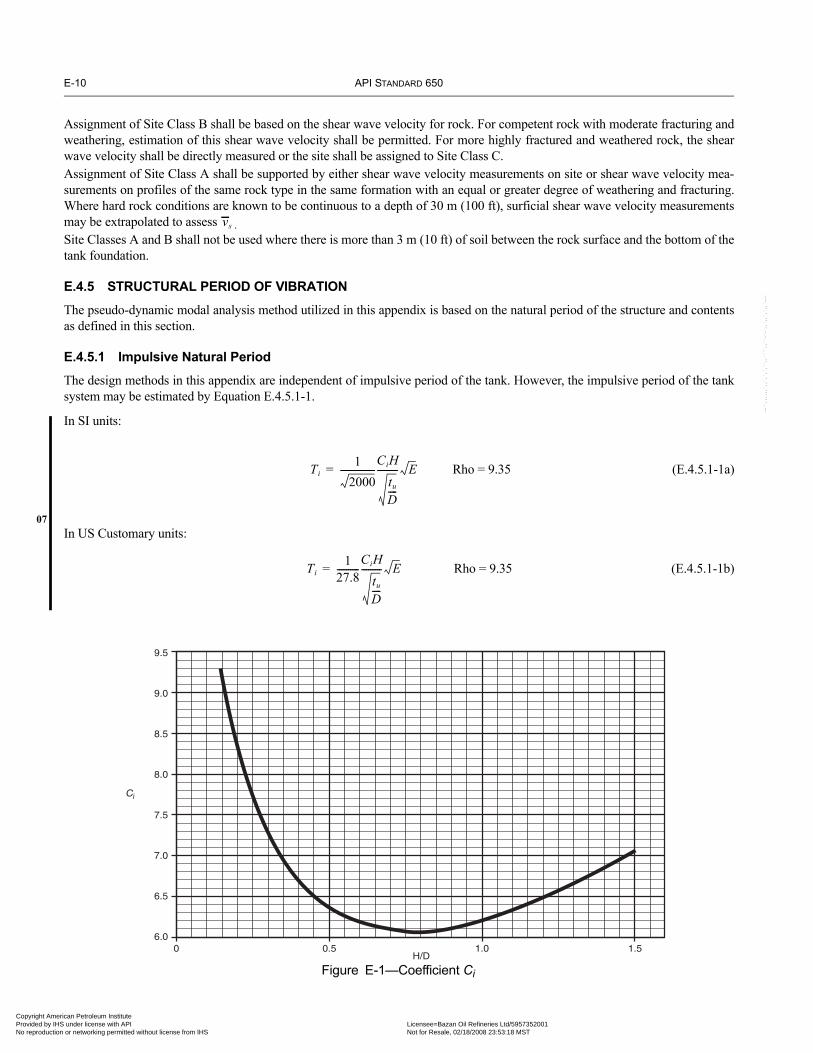
E-10 API STANDARD 650
07
Copyright AmProvided by No reproduc
--``,,,,,,`,,`,`,`,``,,````,,``-`-`,,`,,`,`,,`---
Assignment of Site Class B shall be based on the shear wave velocity for rock. For competent rock with moderate fracturing andweathering, estimation of this shear wave velocity shall be permitted. For more highly fractured and weathered rock, the shearwave velocity shall be directly measured or the site shall be assigned to Site Class C.Assignment of Site Class A shall be supported by either shear wave velocity measurements on site or shear wave velocity mea-surements on profiles of the same rock type in the same formation with an equal or greater degree of weathering and fracturing.Where hard rock conditions are known to be continuous to a depth of 30 m (100 ft), surficial shear wave velocity measurementsmay be extrapolated to assess .Site Classes A and B shall not be used where there is more than 3 m (10 ft) of soil between the rock surface and the bottom of thetank foundation.
E.4.5 STRUCTURAL PERIOD OF VIBRATION
The pseudo-dynamic modal analysis method utilized in this appendix is based on the natural period of the structure and contentsas defined in this section.
E.4.5.1 Impulsive Natural Period
The design methods in this appendix are independent of impulsive period of the tank. However, the impulsive period of the tanksystem may be estimated by Equation E.4.5.1-1.
In SI units:
Rho = 9.35 (E.4.5.1-1a)
In US Customary units:
Rho = 9.35 (E.4.5.1-1b)
vs
9.5
9.0
8.5
8.0
7.5
7.0
6.5
6.00 0.5
H/D
Ci
1.0 1.5
Figure E-1—Coefficient Ci
Ti1
2000----------------
CiHtu
D----
--------- E=
Ti1
27.8----------
CiHtu
D----
--------- E=
erican Petroleum Institute IHS under license with API Licensee=Bazan Oil Refineries Ltd/5957352001
Not for Resale, 02/18/2008 23:53:18 MSTtion or networking permitted without license from IHS

WELDED STEEL TANKS FOR OIL STORAGE E-11
•
07
07
07
Copyright AmericaProvided by IHS uNo reproduction o
E.4.5.2 Convective (Sloshing) Period
The first mode sloshing wave period, in seconds, shall be calculated by Equation E.4.5.2 where Ks is the sloshing period coeffi-cient defined in Equation E.4.5.2-c:
In SI units:
(E.4.5.2-a)
or, in US Customary units:
(E.4.5.2-b)
(E.4.5.2-c)
E.4.6 DESIGN SPECTRAL RESPONSE ACCELERATIONS
The design response spectrum for ground supported, flat-bottom tanks is defined by the following parameters:
E.4.6.1 Spectral Acceleration Coefficients
When probabilistic or mapped design methods are utilized, the spectral acceleration parameters for the design response spectrumare given in Equations E.4.6.1-1 through E.4.6.1-5. Unless otherwise specified by the Purchaser, TL shall be taken as the mappedvalue found in ASCE 7. For tanks falling in SUG I or SUG II, the mapped value of TL shall be used to determine convectiveforces except that a value of TL equal to 4 seconds shall be permitted to be used to determine the sloshing wave height. For tanksfalling in SUG III, the mapped value of TL shall be used to determine both convective forces and sloshing wave height except thatthe importance factor, I, shall be set equal to 1.0 in the determination of sloshing wave height. In regions outside the USA, wherethe regulatory requirements for determining design ground motion differ from the ASCE 7 methods prescribed in this appendix,TL shall be taken as 4 seconds. For sites where only the peak ground acceleration is defined, substitute SP for S0 in Equations E.4.6.1-1 through E.4.6.2-1. Thescaling factor, Q, is defined as 2/3 for the ASCE 7 methods. Q may be taken equal to 1.0 unless otherwise defined in the regulatoryrequirements where ASCE 7 does not apply. Soil amplification coefficients, Fa and Fv; the value of the importance factor, I; andthe ASD response modification factors, Rwi and Rwc, shall be as defined by the local regulatory requirements. If these values arenot defined by the regulations, the values in this appendix shall be used.
Impulsive spectral acceleration parameter, Ai:
(E.4.6.1-1)
However, Ai ≥ 0.007 (E.4.6.1-2)
and, for seismic design categories E and F only,:
(E.4.6.1-3)
Convective spectral acceleration parameter, Ac:
When, TC ≤ TL (E.4.6.1-4)
When, TC > TL (E.4.6.1-5)
Tc 1.8Ks D=
Tc Ks D=
Ks0.578
tanh 3.68HD
---------------⎝ ⎠⎛ ⎞
-----------------------------------=
Ai SDSI
Rwi-------⎝ ⎠⎛ ⎞ 2.5QFaS0
IRwi-------⎝ ⎠⎛ ⎞= =
Ai 0.5S1I
Rwi-------⎝ ⎠⎛ ⎞≥ 0.875SP
IRwi-------⎝ ⎠⎛ ⎞=
Ac KSD11Tc-----⎝ ⎠⎛ ⎞ I
Rwc--------⎝ ⎠⎛ ⎞ 2.5KQFvS0
Ts
Tc-----⎝ ⎠⎛ ⎞ I
Rwc--------⎝ ⎠⎛ ⎞ Ai≤= =
Ac KSD1TL
Tc2-----⎝ ⎠
⎛ ⎞ IRwc--------⎝ ⎠⎛ ⎞ 2.5KQFvS0
TsTL
Tc2----------⎝ ⎠
⎛ ⎞ IRwc--------⎝ ⎠⎛ ⎞ Ai≤= =
--``,,,,,,`,,`,`,`,``,,````,,``-`-`,,`,,`,`,,`---
n Petroleum Institute nder license with API Licensee=Bazan Oil Refineries Ltd/5957352001
Not for Resale, 02/18/2008 23:53:18 MSTr networking permitted without license from IHS

E-12 API STANDARD 650
07
07
•
07
Copyright AmProvided by No reproduc
E.4.6.2 Site-Specific Response Spectra
When site-specific design methods are specified, the seismic parameters shall be defined by Equations E.4.6.2-1 throughE.4.6.2-3.
Impulsive spectral acceleration parameter:
(E.4.6.2-1)
Alternatively, Ai, may be determined using either (1) the impulsive period of the tank system, or (2) assuming the impulsiveperiod = 0.2 sec;
(E.4.6.2-2)
where, Sa* is the ordinate of the 5% damped, site-specific MCE response spectra at the calculated impulsive period including sitesoil effects. See E.4.5.1.
Exception:
Unless otherwise specified by the Purchaser, the value of the impulsive spectral acceleration, Sa*, for flat-bottom tanks withH/D ≤ 0.8 need not exceed 150%g when the tanks are:
• self-anchored, or• mechanically-anchored tanks that are equipped with traditional anchor bolt and chairs at least 450 mm (18 in.) high and are
not otherwise prevented from sliding laterally at least 25 mm (1 in.).
Convective spectral acceleration:
(E.4.6.2-3)
where, Sa* is the ordinate of the 5% damped, site-specific MCE response spectra at the calculated convective period including sitesoil effects (see E.4.5.2).
Alternatively, the ordinate of a site-specific spectrum based on the procedures of E.4.2 for 0.5% damping may be used to deter-mine the value Sa* with K set equal to 1.0.
E.5 Seismic Design FactorsE.5.1 DESIGN FORCES
The equivalent lateral seismic design force shall be determined by the general relationship
F = AWeff (E.5.1-1)
where
A = lateral acceleration coefficient, %g,
Weff = effective weight.
E.5.1.1 Response Modification Factor
The response modification factor for ground supported, liquid storage tanks designed and detailed to these provisions shall be lessthan or equal to the values shown in Table E-4.
Ai 2.5Q IRwi-------⎝ ⎠⎛ ⎞Sa0= *
Ai Q IRwi-------⎝ ⎠⎛ ⎞ Sa*=
Ac QK IRwc--------⎝ ⎠⎛ ⎞Sa= *
erican Petroleum Institute IHS under license with API Licensee=Bazan Oil Refineries Ltd/5957352001
Not for Resale, 02/18/2008 23:53:18 MSTtion or networking permitted without license from IHS
--``,,,,,,`,,`,`,`,``,,````,,``-`-`,,`,,`,`,,`---

WELDED STEEL TANKS FOR OIL STORAGE E-13
•
Copyright AmericaProvided by IHS uNo reproduction o
--``,,,,,,`,,`,`,`,``,,````,,``-`-`,,`,,`,`,,`---
E.5.1.2 Importance Factor
The importance factor (I ) is defined by the SUG and shall be specified by the Purchaser. See E.3 and Table E-5.
E.6 DesignE.6.1 DESIGN LOADS
Ground-supported, flat-bottom tanks, storing liquids shall be designed to resist the seismic forces calculated by considering theeffective mass and dynamic liquid pressures in determining the equivalent lateral forces and lateral force distribution. This is thedefault method for this appendix. The equivalent lateral force base shear shall be determined as defined in the following sections.The seismic base shear shall be defined as the square root of the sum of the squares (SRSS) combination of the impulsive andconvective components unless the applicable regulations require direct sum. For the purposes of this appendix, an alternatemethod using the direct sum of the effects in one direction combined with 40% of the effect in the orthogonal direction is deemedto be equivalent to the SRSS summation.
(E.6.1-1)
where
(E.6.1-2)
(E.6.1-3)
E.6.1.1 Effective Weight of Product
The effective weights Wi and Wc shall be determined by multiplying the total product weight, Wp, by the ratios Wi/Wp and Wc/Wp,respectively, Equations E.6.1.1-1 through E.6.1.1-3.When D/H is greater than or equal to 1.333, the effective impulsive weight is defined in Equation E.6.1.1-1:
(E.6.1.1-1)
When D/H is less than 1.333, the effective impulsive weight is defined in Equation E.6.1.1-2:
(E.6.1.1-2)
Table E-4—Response Modification Factors for ASD Methods
Anchorage system Rwi, (impulsive) Rwc, (convective)
Self-anchored 3.5 2
Mechanically-anchored 4 2
Table E-5—Importance Factor (I ) and Seismic Use Group Classification
Seismic Use Group I
I 1.0
II 1.25
III 1.5
V Vi2 Vc
2+=
Vi Ai Ws Wr Wf Wi+ + +( )=
Vc AcWc=
Wi
0.866DH----⎝ ⎠
⎛ ⎞tanh
0.866DH----
----------------------------------Wp=
Wi 1.0 0.218DH----– Wp=
n Petroleum Institute nder license with API Licensee=Bazan Oil Refineries Ltd/5957352001
Not for Resale, 02/18/2008 23:53:18 MSTr networking permitted without license from IHS

E-14 API STANDARD 650
07
07
07
Copyright AmProvided by No reproduc
--``,,,,,,`,,`,`,`,``,,````,,``-`-`,,`,,`,`,,`---
The effective convective weight is defined in Equation E.6.1.1-3:
(E.6.1.1-3)
E.6.1.2 Center of Action for Effective Lateral Forces
The moment arm from the base of the tank to the center of action for the equivalent lateral forces from the liquid is defined byEquations E.6.1.2.1-1 through E.6.1.2.2-3.The center of action for the impulsive lateral forces for the tank shell, roof and appurtenances is assumed to act through the centerof gravity of the component.
E.6.1.2.1 Center of Action for Ringwall Overturning Moment
The ringwall moment, Mrw, is the portion of the total overturning moment that acts at the base of the tank shell perimeter. Thismoment is used to determine loads on a ringwall foundation, the tank anchorage forces, and to check the longitudinal shellcompression.The heights from the bottom of the tank shell to the center of action of the lateral seismic forces applied to Wi and Wc, Xi and Xc,may be determined by multiplying H by the ratios Xi /H and Xc /H, respectively, obtained for the ratio D/H by using EquationsE.6.1.2.1-1 through E.6.1.2.1-3.
When D/H is greater than or equal to 1.3333, the height Xi is determined by Equation E.6.1.2.1-1:
(E.6.1.2.1-1)
When D/H is less than 1.3333, the height Xi is determined by Equation E.6.1.2.1-2:
(E.6.1.2.1-2)
The height Xc is determined by Equation E.6.1.2.1-3:
(E.6.1.2.1-3)
E.6.1.2.2 Center of Action for Slab Overturning Moment
The “slab” moment, Ms, is the total overturning moment acting across the entire tank base cross-section. This overturningmoment is used to design slab and pile cap foundations.When D/H is greater than or equal to 1.333, the height Xis is determined by Equation E.6.1.2.2-1:
(E.6.1.2.2-1)
When D/H is less than 1.333, the height Xis is determined by Equation E.6.1.2.2-2:
(E.6.1.2.2-2)
Wc 0.230DH---- 3.67H
D---------------⎝ ⎠⎛ ⎞tanh=
Xi 0.375H=
Xi 0.5 0.094DH----– H=
Xc 1.0
3.67HD
---------------⎝ ⎠⎛ ⎞cosh 1–
3.67HD
--------------- 3.67HD
---------------⎝ ⎠⎛ ⎞sinh
-----------------------------------------------– H=
Xis 0.375 1.0 1.3330.866D
H----
0.866DH----⎝ ⎠
⎛ ⎞tanh---------------------------------- 1.0–
⎝ ⎠⎜ ⎟⎜ ⎟⎜ ⎟⎛ ⎞
+ H=
Xis 0.500 0.060DH----+ H=
erican Petroleum Institute IHS under license with API Licensee=Bazan Oil Refineries Ltd/5957352001
Not for Resale, 02/18/2008 23:53:18 MSTtion or networking permitted without license from IHS
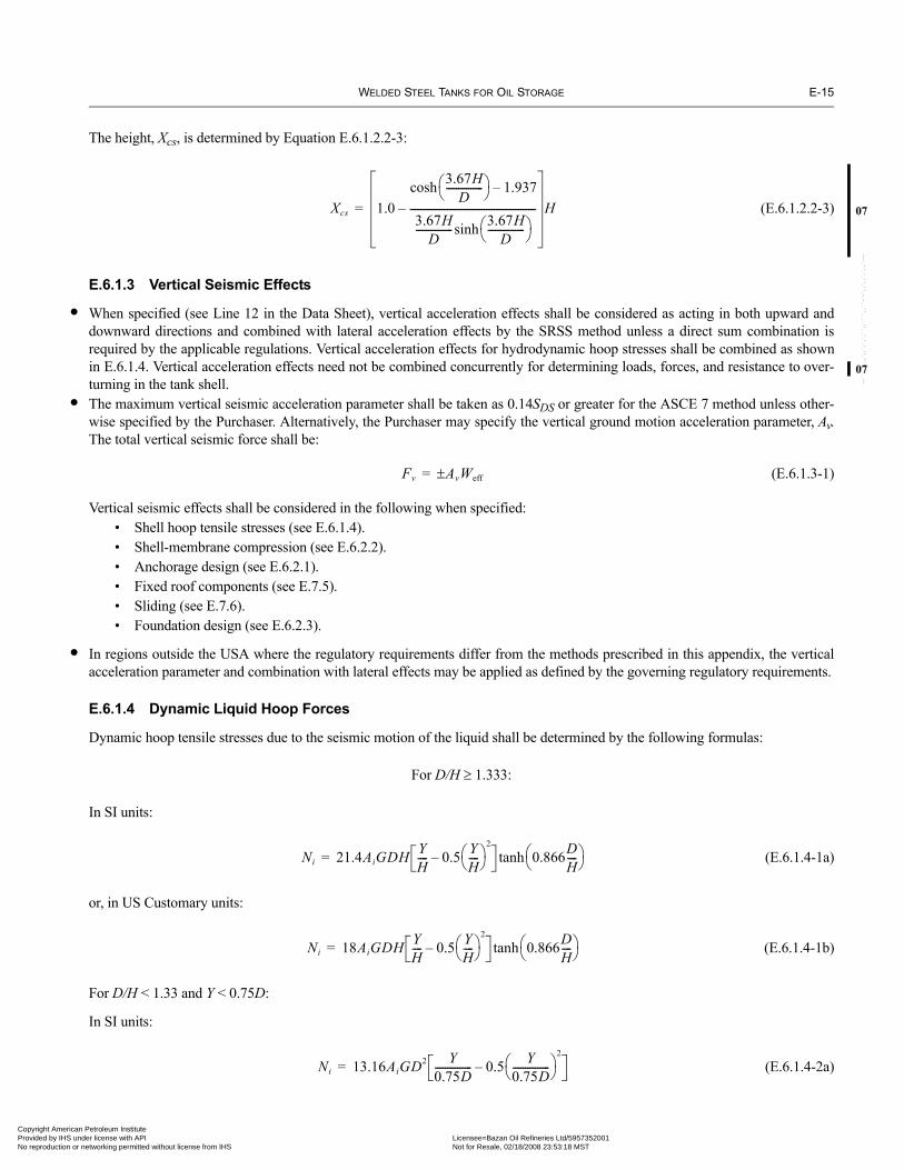
WELDED STEEL TANKS FOR OIL STORAGE E-15
07
•
07
•
•
Copyright AmericaProvided by IHS uNo reproduction o
--``,,,,,,`,,`,`,`,``,,````,,``-`-`,,`,,`,`,,`---
The height, Xcs, is determined by Equation E.6.1.2.2-3:
(E.6.1.2.2-3)
E.6.1.3 Vertical Seismic Effects
When specified (see Line 12 in the Data Sheet), vertical acceleration effects shall be considered as acting in both upward anddownward directions and combined with lateral acceleration effects by the SRSS method unless a direct sum combination isrequired by the applicable regulations. Vertical acceleration effects for hydrodynamic hoop stresses shall be combined as shownin E.6.1.4. Vertical acceleration effects need not be combined concurrently for determining loads, forces, and resistance to over-turning in the tank shell.The maximum vertical seismic acceleration parameter shall be taken as 0.14SDS or greater for the ASCE 7 method unless other-wise specified by the Purchaser. Alternatively, the Purchaser may specify the vertical ground motion acceleration parameter, Av.The total vertical seismic force shall be:
(E.6.1.3-1)
Vertical seismic effects shall be considered in the following when specified:• Shell hoop tensile stresses (see E.6.1.4). • Shell-membrane compression (see E.6.2.2).• Anchorage design (see E.6.2.1).• Fixed roof components (see E.7.5).• Sliding (see E.7.6).• Foundation design (see E.6.2.3).
In regions outside the USA where the regulatory requirements differ from the methods prescribed in this appendix, the verticalacceleration parameter and combination with lateral effects may be applied as defined by the governing regulatory requirements.
E.6.1.4 Dynamic Liquid Hoop Forces
Dynamic hoop tensile stresses due to the seismic motion of the liquid shall be determined by the following formulas:
For D/H ≥ 1.333:
In SI units:
(E.6.1.4-1a)
or, in US Customary units:
(E.6.1.4-1b)
For D/H < 1.33 and Y < 0.75D:
In SI units:
(E.6.1.4-2a)
Xcs 1.0
3.67HD
---------------⎝ ⎠⎛ ⎞cosh 1.937–
3.67HD
--------------- 3.67HD
---------------⎝ ⎠⎛ ⎞sinh
---------------------------------------------------– H=
Fv Av± Weff=
Ni 21.4AiGDH YH---- 0.5 Y
H----⎝ ⎠⎛ ⎞
2
– 0.866DH----⎝ ⎠
⎛ ⎞tanh=
Ni 18AiGDH YH---- 0.5 Y
H----⎝ ⎠⎛ ⎞
2
– 0.866DH----⎝ ⎠
⎛ ⎞tanh=
Ni 13.16AiGD2 Y0.75D--------------- 0.5 Y
0.75D---------------⎝ ⎠⎛ ⎞
2
–=
n Petroleum Institute nder license with API Licensee=Bazan Oil Refineries Ltd/5957352001
Not for Resale, 02/18/2008 23:53:18 MSTr networking permitted without license from IHS

E-16 API STANDARD 650
07
07
07
•
Copyright AmProvided by No reproduc
or, in US Customary units:
(E.6.1.4-2b)
For D/H < 1.333 and Y ≥ 0.75D:
In SI units:
(E.6.1.4-3a)
or, in US Customary units:
(E.6.1.4-3b)
For all proportions of D/H:
In SI units:
(E.6.1.4-4a)
or, in US Customary units:
(E.6.1.4-4b)
When the Purchaser specifies that vertical acceleration need not be considered (i.e., Av = 0), the combined hoop stress shall bedefined by Equation E.6.1.4-5. The dynamic hoop tensile stress shall be directly combined with the product hydrostatic designstress in determining the total stress.
(E.6.1.4-5)
When vertical acceleration is specified.
(E.6.1.4-6)
E.6.1.5 Overturning Moment
The seismic overturning moment at the base of the tank shell shall be the SRSS summation of the impulsive and convective com-ponents multiplied by the respective moment arms to the center of action of the forces unless otherwise specified.
Ringwall Moment, Mrw:
(E.6.1.5-1)
Slab Moment, Ms:
(E.6.1.5-2)
Ni 11AiGD2 Y0.75D--------------- 0.5 Y
0.75D---------------⎝ ⎠⎛ ⎞
2
–=
Ni 6.6AiGD2=
Ni 5.54AiGD2=
Nc
33.1AcCcSGD2 3.68 H Y–( )D
----------------------------cosh
3.68HD
---------------cosh-----------------------------------------------------------------------------------=
Nc
3.9AcCcSGD2 3.68 H Y–( )D
----------------------------cosh
3.68HD
---------------cosh--------------------------------------------------------------------------------=
σT σh σs±Nh Ni
2 Nc2+±
t--------------------------------= =
σT σh σs±Nh Ni
2 Nc2 AvNh( )2+ +±
t-----------------------------------------------------------= =
Mrw Ai WiXi WsXs WrXr+ +( )[ ]2 Ac WcXc( )[ ]2+=
Ms Ai WiXis WsXs WrXr+ +( )[ ]2 Ac WcXcs( )[ ]2+=
erican Petroleum Institute IHS under license with API Licensee=Bazan Oil Refineries Ltd/5957352001
Not for Resale, 02/18/2008 23:53:18 MSTtion or networking permitted without license from IHS
--``,,,,,,`,,`,`,`,``,,````,,``-`-`,,`,,`,`,,`---

WELDED STEEL TANKS FOR OIL STORAGE E-17
07
07
•
07
07
Copyright AmericaProvided by IHS uNo reproduction o
Unless a more rigorous determination is used, the overturning moment at the bottom of each shell ring shall be defined by linearapproximation using the following:
1. If the tank is equipped with a fixed roof, the impulsive shear and overturning moment is applied at the top of the shell.2. The impulsive shear and overturning moment for each shell course is included based on the weight and centroid of eachcourse.
3. The overturning moment due to the liquid is approximated by a linear variation that is equal to the ringwall moment, Mrw atthe base of the shell to zero at the maximum liquid level.
E.6.1.6 Soil-Structure Interaction
If specified by the Purchaser, the effects of soil-structure interaction on the effective damping and period of vibration may be con-sidered for tanks in accordance with ASCE 7 with the following limitations:
• Tanks shall be equipped with a reinforced concrete ringwall, mat or similar type foundation supported on grade. Soil struc-ture interaction effects for tanks supported on granular berm or pile type foundation are outside the scope of this appendix.
• The tanks shall be mechanically anchored to the foundation.• The value of the base shear and overturning moments for the impulsive mode including the effects of soil-structure interac-
tion shall not be less than 80% of the values determined without consideration of soil-structure interaction.• The effective damping factor for the structure-foundation system shall not exceed 20%.
E.6.2 RESISTANCE TO DESIGN LOADS
The allowable stress design (ASD) method is utilized in this appendix. Allowable stresses in structural elements applicable to nor-mal operating conditions may be increased by 33% when the effects of the design earthquake are included unless otherwise spec-ified in this appendix.
E.6.2.1 Anchorage
Resistance to the design overturning (ringwall) moment at the base of the shell may be provided by:• The weight of the tank shell, weight of roof reaction on shell Wrs, and by the weight of a portion of the tank contents adja-
cent to the shell for unanchored tanks.• Mechanical anchorage devices.
E.6.2.1.1 Self-Anchored
For self-anchored tanks, a portion of the contents may be used to resist overturning. The anchorage provided is dependent on theassumed width of a bottom annulus uplifted by the overturning moment. The resisting annulus may be a portion of the tank bot-tom (i.e., ta = tb) or a separate butt-welded annular ring (i.e., ta > tb). The resisting force of the annulus that lifts off the foundationshall be determined by Equation E.6.2.1.1-1.
In SI units:
(E.6.2.1.1-1a)
or, in US Customary units:
(E.6.2.1.1-1b)
Equation E.6.2.1.1-1 for wa applies whether or not a thickened bottom annulus is used. The tank is self-anchored providing the following conditions are met:
1. The resisting force is adequate for tank stability (i.e., the anchorage ratio, J ≤ 1.54).2. The maximum width of annulus for determining the resisting force is 3.5% of the tank diameter.
3. The shell compression satisfies E.6.2.2.
4. The required annular plate thickness does not exceed the thickness of the bottom shell course.
5. Piping flexibility requirements are satisfied.
wa 99ta FyHGe 1.96 HDGc≤=
wa 7.9ta FyHGe 1.28 HDGc≤=
n Petroleum Institute nder license with API Licensee=Bazan Oil Refineries Ltd/5957352001
Not for Resale, 02/18/2008 23:53:18 MSTr networking permitted without license from IHS
--``,,,,,,`,,`,`,`,``,,````,,``-`-`,,`,,`,`,,`---

E-18 API STANDARD 650
07
07
07
•
Copyright AmProvided by No reproduc
E.6.2.1.1.1 Anchorage Ratio, J
(E.6.2.1.1.1-1)
where
(E.6.2.1.1.1-2)
E.6.2.1.1.2 Annular Plate Requirements
The thickness of the tank bottom plate provided under the shell may be greater than or equal to the thickness of the general tankfloor plate (i.e., ta ≥ tb) with the following restrictions.
Note: In thickening the bottom annulus, the intent is not to force a thickening of the lowest shell course, thereby inducing an abrupt thicknesschange in the shell, but rather to impose a limit on the bottom annulus thickness based on the shell design.
1. The thickness, ta, used to calculate wa in Equation E.6.2.1.1-1b shall not exceed the first shell course thickness, ts, less theshell corrosion allowance.
2. Nor shall the thickness, ta, used in Equation E.6.2.1.1-1b exceed the actual thickness of the plate under the shell less thecorrosion allowance for tank bottom.
3. When the bottom plate under the shell is thicker than the remainder of the tank bottom (i.e., ta > tb) the minimum projectionof the supplied thicker annular plate inside the tank wall, Ls, shall be equal to or greater than L:
In SI units:
(E.6.2.1.1.2-1a)
or, in US Customary units:
(E.6.2.1.1.2-1b)
E.6.2.1.2 Mechanically-Anchored
If the tank configuration is such that the self-anchored requirements can not be met, the tank must be anchored with mechanicaldevices such as anchor bolts or straps.When tanks are anchored, the resisting weight of the product shall not be used to reduce the calculated uplift load on the anchors.The anchors shall be sized to provide for at least the following minimum anchorage resistance:
(E.6.2.1.2-1)
Table E-6—Anchorage Ratio Criteria
Anchorage RatioJ Criteria
J ≤ 0.785 No calculated uplift under the design seismic overturning moment. The tank is self-anchored.
0.785 < J ≤1.54 Tank is uplifting, but the tank is stable for the design load providing the shell compres-sion requirements are satisfied. Tank is self-anchored.
J > 1.54 Tank is not stable and cannot be self-anchored for the design load. Modify the annular plate if L < 0.035D is not controlling or add mechanical anchorage.
JMrw
D2 wt 1 0.4Av–( ) wa+( )-------------------------------------------------------=
wtWs
πD------- wrs+=
L 0.01723ta Fy HGe⁄ 0.035D≤=
L 0.216ta Fy HGe⁄ 0.035D≤=
wAB1.273Mrw
D2----------------------- wt 1 0.4Av–( )–⎝ ⎠⎛ ⎞=
erican Petroleum Institute IHS under license with API Licensee=Bazan Oil Refineries Ltd/5957352001
Not for Resale, 02/18/2008 23:53:18 MSTtion or networking permitted without license from IHS
--``,,,,,,`,,`,`,`,``,,````,,``-`-`,,`,,`,`,,`---
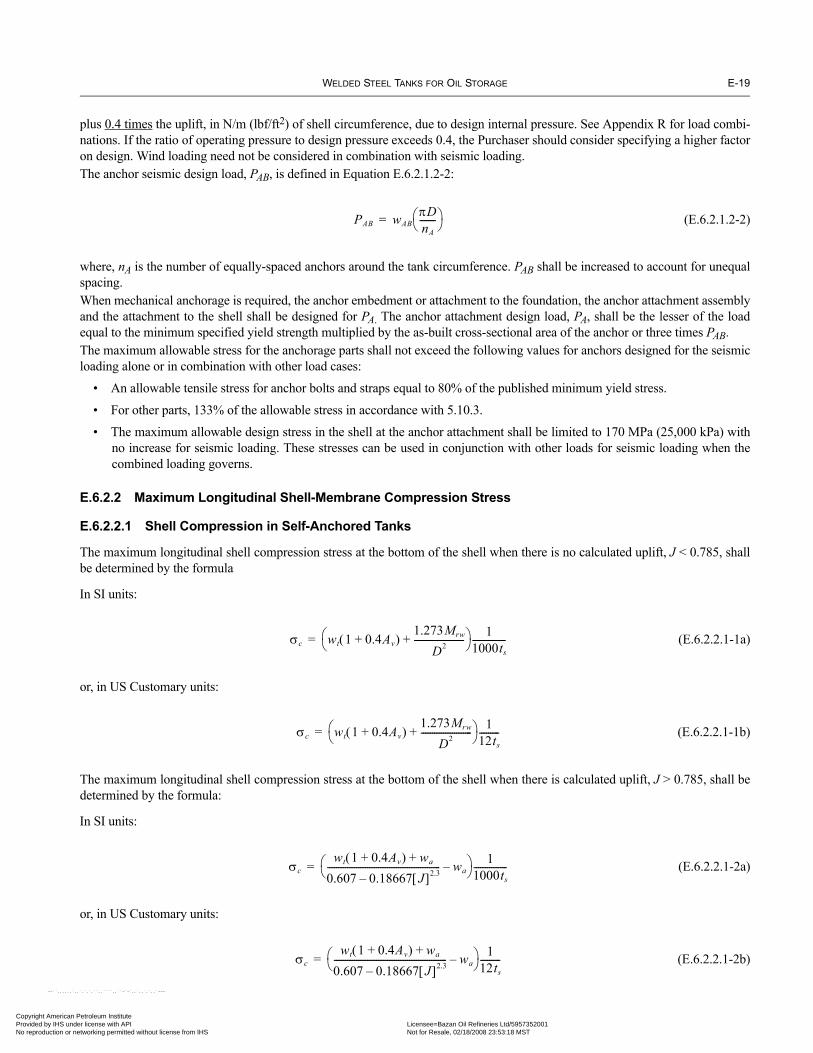
WELDED STEEL TANKS FOR OIL STORAGE E-19
Copyright AmericaProvided by IHS uNo reproduction o
--``,,,,,
plus 0.4 times the uplift, in N/m (lbf/ft2) of shell circumference, due to design internal pressure. See Appendix R for load combi-nations. If the ratio of operating pressure to design pressure exceeds 0.4, the Purchaser should consider specifying a higher factoron design. Wind loading need not be considered in combination with seismic loading.The anchor seismic design load, PAB, is defined in Equation E.6.2.1.2-2:
(E.6.2.1.2-2)
where, nA is the number of equally-spaced anchors around the tank circumference. PAB shall be increased to account for unequalspacing.When mechanical anchorage is required, the anchor embedment or attachment to the foundation, the anchor attachment assemblyand the attachment to the shell shall be designed for PA. The anchor attachment design load, PA, shall be the lesser of the loadequal to the minimum specified yield strength multiplied by the as-built cross-sectional area of the anchor or three times PAB.The maximum allowable stress for the anchorage parts shall not exceed the following values for anchors designed for the seismicloading alone or in combination with other load cases:
• An allowable tensile stress for anchor bolts and straps equal to 80% of the published minimum yield stress.
• For other parts, 133% of the allowable stress in accordance with 5.10.3.
• The maximum allowable design stress in the shell at the anchor attachment shall be limited to 170 MPa (25,000 kPa) withno increase for seismic loading. These stresses can be used in conjunction with other loads for seismic loading when thecombined loading governs.
E.6.2.2 Maximum Longitudinal Shell-Membrane Compression Stress
E.6.2.2.1 Shell Compression in Self-Anchored Tanks
The maximum longitudinal shell compression stress at the bottom of the shell when there is no calculated uplift, J < 0.785, shallbe determined by the formula
In SI units:
(E.6.2.2.1-1a)
or, in US Customary units:
(E.6.2.2.1-1b)
The maximum longitudinal shell compression stress at the bottom of the shell when there is calculated uplift, J > 0.785, shall bedetermined by the formula:
In SI units:
(E.6.2.2.1-2a)
or, in US Customary units:
(E.6.2.2.1-2b)
PAB wABπDnA-------⎝ ⎠⎛ ⎞=
σc wt 1 0.4Av+( )1.273Mrw
D2-----------------------+⎝ ⎠⎛ ⎞ 1
1000ts---------------=
σc wt 1 0.4Av+( )1.273Mrw
D2-----------------------+⎝ ⎠⎛ ⎞ 1
12ts---------=
σcwt 1 0.4Av+( ) wa+
0.607 0.18667 J[ ]2.3–--------------------------------------------------- wa–⎝ ⎠⎛ ⎞ 1
1000ts---------------=
σcwt 1 0.4Av+( ) wa+
0.607 0.18667 J[ ]2.3–--------------------------------------------------- wa–⎝ ⎠⎛ ⎞ 1
12ts---------=
,`,,`,`,`,``,,````,,``-`-`,,`,,`,`,,`---
n Petroleum Institute nder license with API Licensee=Bazan Oil Refineries Ltd/5957352001
Not for Resale, 02/18/2008 23:53:18 MSTr networking permitted without license from IHS

E-20 API STANDARD 650
07
07
07
Copyright AmProvided by No reproduc
E.6.2.2.2 Shell Compression in Mechanically-Anchored Tanks
The maximum longitudinal shell compression stress at the bottom of the shell for mechanically-anchored tanks shall be deter-mined by the formula
In SI units:
(E.6.2.2.2-1a)
or, in US Customary units:
(E.6.2.2.2-1b)
E.6.2.2.3 Allowable Longitudinal Shell-Membrane Compression Stress in Tank Shell
The maximum longitudinal shell compression stress sc must be less than the seismic allowable stress FC, which is determined bythe following formulas and includes the 33% increase for ASD. These formulas for FC, consider the effect of internal pressuredue to the liquid contents.When GHD2/ t2 is greater than or equal to 44 (SI units) (106 US Customary units),
In SI units:
(E.6.2.2.3-1a)
or, in US Customary units:
(E.6.2.2.3-1b)
In SI units:
When GHD2/ t2 is less than 44:
(E.6.2.2.3-2a)
or, in US Customary units:
When GHD2/t2 is less than 1 × 10⁶:
(E.6.2.2.3-2b)
If the thickness of the bottom shell course calculated to resist the seismic overturning moment is greater than the thicknessrequired for hydrostatic pressure, both excluding any corrosion allowance, then the calculated thickness of each upper shellcourse for hydrostatic pressure shall be increased in the same proportion, unless a special analysis is made to determine the seis-mic overturning moment and corresponding stresses at the bottom of each upper shell course (see E.6.1.5).
E.6.2.3 Foundation
Foundations and footings for mechanically-anchored flat-bottom tanks shall be proportioned to resist peak anchor uplift and over-turning bearing pressure. Product and soil load directly over the ringwall and footing may be used to resist the maximum anchoruplift on the foundation, provided the ringwall and footing are designed to carry this eccentric loading. Product load shall not be used to reduce the anchor load. When vertical seismic accelerations are applicable, the product load directly over the ringwall and footing:
σc wt 1 0.4Av+( )1.273Mrw
D2-----------------------+⎝ ⎠⎛ ⎞ 1
1000ts---------------=
σc wt 1 0.4Av+( )1.273Mrw
D2-----------------------+⎝ ⎠⎛ ⎞ 1
12ts---------=
FC 83 ts D⁄=
FC 106 ts D⁄=
FC 8ts 2.5D( ) 7.5 GH( )+ 0.5Fty<⁄=
FC 106 ts 2.5D( ) 600 GH( )+ 0.5Fty<⁄=
erican Petroleum Institute IHS under license with API Licensee=Bazan Oil Refineries Ltd/5957352001
Not for Resale, 02/18/2008 23:53:18 MSTtion or networking permitted without license from IHS
--``,,,,,,`,,`,`,`,``,,````,,``-`-`,,`,,`,`,,`---

WELDED STEEL TANKS FOR OIL STORAGE E-21
Copyright AmericaProvided by IHS uNo reproduction o
1. When used to resist the maximum anchor uplift on the foundation, the product pressure shall be multiplied by a factor of(1 – 0.4Av) and the foundation ringwall and footing shall be designed to resist the eccentric loads with or without the verticalseismic accelerations.
2. When used to evaluate the bearing (downward) load, the product pressure over the ringwall shall be multiplied by a factorof (1 + 0.4Av) and the foundation ringwall and footing shall be designed to resist the eccentric loads with or without the verti-cal seismic accelerations.
The overturning stability ratio for mechanically-anchored tank system excluding vertical seismic effects shall be 2.0 or greater asdefined in Equation E.6.2.3-1.
(E.6.2.3-1)
Ringwalls for self-anchored flat-bottom tanks shall be proportioned to resist overturning bearing pressure based on the maximumlongitudinal shell compression force at the base of the shell in Equation E.6.2.3-2. Slabs and pile caps for self-anchored tanksshall be designed for the peak loads determined in E.6.2.2.1.
(E.6.2.3-2)
E.6.2.4 Hoop Stresses
The maximum allowable hoop tension membrane stress for the combination of hydrostatic product and dynamic membrane hoopeffects shall be the lesser of:
• The basic allowable membrane in this Standard for the shell plate material increased by 33%; or,• 0.9Fy times the joint efficiency where Fy is the lesser of the published minimum yield strength of the shell material or weld
material.
E.7 Detailing RequirementsE.7.1 ANCHORAGE
Tanks at grade are permitted to be designed without anchorage when they meet the requirements for self-anchored tanks in thisappendix. The following special detailing requirements shall apply to steel tank mechanical anchors in seismic regions where SDS > 0.05g.
E.7.1.1 Self-Anchored
For tanks in SUG III and located where SDS = 0.5g or greater, butt-welded annular plates shall be required. Annular plates exceed-ing 10 mm (3/8 in.) thickness shall be butt-welded. The weld of the shell to the bottom annular plate shall be checked for thedesign uplift load.
E.7.1.2 Mechanically-Anchored
When mechanical-anchorage is required, at least six anchors shall be provided. The spacing between anchors shall not exceed 3 m(10 ft).When anchor bolts are used, they shall have a minimum diameter of 25 mm (1 in.), excluding any corrosion allowance. Carbonsteel anchor straps shall be 6 mm (1/4 in.) minimum thickness and have a minimum corrosion allowance of 1.5 mm (1/16 in.) oneach surface for a distance at least 75 mm (3 in.) but not more than 300 mm (12 in.) above the surface of the concrete.Hooked anchor bolts (L- or J-shaped embedded bolts) or other anchorage systems based solely on bond or mechanical friction shallnot be used when seismic design is required by this appendix. Post-installed anchors may be used provided that testing validates theirability to develop yield load in the anchor under cyclic loads in cracked concrete and meet the requirements of ACI 355.
0.5D Wp Wf WT Wfd Wg+ + + +[ ]Ms
----------------------------------------------------------------------------- 2.0≥
Pf wt 1 0.4Av+( )1.273Mrw
D2-----------------------+⎝ ⎠⎛ ⎞=
n Petroleum Institute nder license with API Licensee=Bazan Oil Refineries Ltd/5957352001
Not for Resale, 02/18/2008 23:53:18 MSTr networking permitted without license from IHS
--``,,,,,,`,,`,`,`,``,,````,,``-`-`,,`,,`,`,,`---

E-22 API STANDARD 650
•
07
07
07
07
07
07
Copyright AmProvided by No reproduc
E.7.2 FREEBOARD
Sloshing of the liquid within the tank or vessel shall be considered in determining the freeboard required above the top capacityliquid level. A minimum freeboard shall be provided per Table E-7. See E.4.6.1. Purchaser shall specify whether freeboard isdesired for SUG I tanks. Freeboard is required for SUG II and SUG III tanks. The height of the sloshing wave above the productdesign height can be estimated by:
(see Note c in Table E-7) (E.7.2-1)
For SUG I and II,
When, TC ≤ 4 (E.7.2-2)
When, TC > 4 (E.7.2-3)
For SUG III,
When, TC ≤ TL (E.7.2-4)
When, TC > TL (E.7.2-5)
E.7.3 PIPING FLEXIBILITY
Piping systems connected to tanks shall consider the potential movement of the connection points during earthquakes and providesufficient flexibility to avoid release of the product by failure of the piping system. The piping system and supports shall bedesigned so as to not impart significant mechanical loading on the attachment to the tank shell. Local loads at piping connectionsshall be considered in the design of the tank shell. Mechanical devices which add flexibility such as bellows, expansion joints, andother flexible apparatus may be used when they are designed for seismic loads and displacements.Unless otherwise calculated, piping systems shall provide for the minimum displacements in Table E-8 at working stress levels(with the 33% increase for seismic loads) in the piping, supports and tank connection. The piping system and tank connectionshall also be designed to tolerate 1.4Cd times the working stress displacements given in Table E-8 without rupture, although per-manent deformations and inelastic behavior in the piping supports and tank shell is permitted. For attachment points located abovethe support or foundation elevation, the displacements in Table E-8 shall be increased to account for drift of the tank or vessel.
Table E-7—Minimum Required Freeboard
Value of SDS SUG I SUG II SUG III
SDS < 0.33g 0.7δs (a) 0.7δs (a) δs (c)
SDS ≥ 0.33g 0.7δs (a) 0.7δs (b) δs (c)
a. A freeboard of 0.7δs is recommended for economic considerations but not required.b. A freeboard equal to 0.7δs is required unless one of the following alternatives are provided: 1. Secondary containment is provided to control the product spill. 2. The roof and tank shell are designed to contain the sloshing liquid. c. Freeboard equal to the calculated wave height, δs, is required unless one of the following alternatives are provided: 1. Secondary containment is provided to control the product spill. 2. The roof and tank shell are designed to contain the sloshing liquid.
δs 0.5DAf=
Af KSD1I 1TC-----⎝ ⎠⎛ ⎞ 2.5KQFvS0I
TS
TC-----⎝ ⎠⎛ ⎞= =
Af KSD1I 4TC
2-----⎝ ⎠⎛ ⎞ 2.5KQFvS0I
4TS
TC2--------⎝ ⎠
⎛ ⎞= =
Af KSD11TC-----⎝ ⎠⎛ ⎞ 2.5KQFvS0
TS
TC-----⎝ ⎠⎛ ⎞= =
Af KSD1TL
TC2-----⎝ ⎠
⎛ ⎞ 2.5KQFvS0TSTL
TC2-----------⎝ ⎠
⎛ ⎞= =
--``,,,,,,`,,`,`,`,``,,````,,``-`-`,,`,,`,`,,`---
erican Petroleum Institute IHS under license with API Licensee=Bazan Oil Refineries Ltd/5957352001
Not for Resale, 02/18/2008 23:53:18 MSTtion or networking permitted without license from IHS

WELDED STEEL TANKS FOR OIL STORAGE E-23
07
Copyright AmericaProvided by IHS uNo reproduction o
--``,,,,,,`,,`,`,`,``,,````,,``-`-`,,`,,`,`,,`---
The values given in Table E-8 do not include the influence of relative movements of the foundation and piping anchorage pointsdue to foundation movements (such as settlement or seismic displacements). The effects of foundation movements shall beincluded in the design of the piping system design, including the determination of the mechanical loading on the tank or vesselconsideration of the total displacement capacity of the mechanical devices intended to add flexibility.When SDS < 0.1, the values in Table E-7 may be reduced to 70% of the values shown.
E.7.3.1 Method for Estimating Tank Uplift
The maximum uplift at the base of the tank shell for a self-anchored tank constructed to the criteria for annular plates (see E.6.2.1)may be approximated by Equation E.7.3.1-1:
In SI units:
(E.7.3.1-1a)
Or, in US Customary units:
(E.7.3.1-1b)
where
tb = calculated annular ring t holdown.
E.7.4 CONNECTIONS
Connections and attachments for anchorage and other lateral force resisting components shall be designed to develop the strengthof the anchor (e.g., minimum published yield strength, Fy in direct tension, plastic bending moment), or 4 times the calculated ele-ment design load.Penetrations, manholes, and openings in shell components shall be designed to maintain the strength and stability of the shell tocarry tensile and compressive membrane shell forces.The bottom connection on an unanchored flat-bottom tank shall be located inside the shell a sufficient distance to minimize dam-age by uplift. As a minimum, the distance measured to the edge of the connection reinforcement shall be the width of the calcu-lated unanchored bottom hold-down plus 300 mm (12 in.)
E.7.5 INTERNAL COMPONENTS
The attachments of internal equipment and accessories which are attached to the primary liquid- or pressure-retaining shell or bot-tom, or provide structural support for major components shall be designed for the lateral loads due to the sloshing liquid in addi-tion to the inertial forces.
Table E-8—Design Displacements for Piping Attachments
Condition
ASD Design Displacement
mm (in.)
Mechanically-anchored tanksUpward vertical displacement relative to support or foundation:Downward vertical displacement relative to support or foundation:Range of horizontal displacement (radial and tangential) relative to support or foundation:
25 (1)13 (0.5)13 (0.5)
Self-anchored tanksUpward vertical displacement relative to support or foundation:
Anchorage ratio less than or equal to 0.785:Anchorage ratio greater than 0.785:
Downward vertical displacement relative to support or foundation: For tanks with a ringwall/mat foundation: For tanks with a berm foundation:
Range of horizontal displacement (radial and tangential) relative to support or foundation
25 (1)100 (4)
13 (0.5)25 (1)
50 (2)
yu12.10FyL
2
tb------------------------=
yuFyL
2
83300tb-------------------=
n Petroleum Institute nder license with API Licensee=Bazan Oil Refineries Ltd/5957352001
Not for Resale, 02/18/2008 23:53:18 MSTr networking permitted without license from IHS

E-24 API STANDARD 650
•
07
Copyright AmProvided by No reproduc
Seismic design of roof framing and columns shall be made if specified by the Purchaser. The Purchaser shall specify live loadsand amount of vertical acceleration to be used in seismic design of the roof members. Columns shall be designed for lateral liquidinertia loads and acceleration as specified by the Purchaser. Seismic beam-column design shall be based upon the primary mem-ber allowable stresses set forth in AISC (ASD), increased by one-third for seismic loading. Internal columns shall be guided or supported to resist lateral loads (remain stable) even if the roof components are not specified to bedesigned for the seismic loads, including tanks that need not be designed for seismic ground motion in this appendix (see E.1).
E.7.6 SLIDING RESISTANCE
The transfer of the total lateral shear force between the tank and the subgrade shall be considered.For self-anchored flat-bottom steel tanks, the overall horizontal seismic shear force shall be resisted by friction between the tankbottom and the foundation or subgrade. Self-anchored storage tanks shall be proportioned such that the calculated seismic baseshear, V, does not exceed Vs:The friction coefficient, m, shall not exceed 0.4. Lower values of the friction coefficient should be used if the interface of the bot-tom to supporting foundation does not justify the friction value above (e.g., leak detection membrane beneath the bottom with alower friction factor, smooth bottoms, etc.).
(E.7.6-1)
No additional lateral anchorage is required for mechanically-anchored steel tanks designed in accordance with this appendix eventhough small movements of approximately 25 mm (1 in.) are possible.The lateral shear transfer behavior for special tank configurations (e.g., shovel bottoms, highly crowned tank bottoms, tanks ongrillage) can be unique and are beyond the scope of this appendix.
E.7.7 LOCAL SHEAR TRANSFER
Local transfer of the shear from the roof to the shell and the shell of the tank into the base shall be considered. For cylindricaltanks, the peak local tangential shear per unit length shall be calculated by:
(E.7.7-1)
Tangential shear in flat-bottom steel tanks shall be transferred through the welded connection to the steel bottom. The shear stressin the weld shall not exceed 80% of the weld or base metal yield stress. This transfer mechanism is deemed acceptable for steeltanks designed in accordance with the provisions and SDS < 1.0g.
E.7.8 CONNECTIONS WITH ADJACENT STRUCTURES
Equipment, piping, and walkways or other appurtenances attached to the tank or adjacent structures shall be designed to accom-modate the elastic displacements of the tank imposed by design seismic forces amplified by a factor of 3.0 plus the amplified dis-placement of the other structure.
E.7.9 SHELL SUPPORT
Self-anchored tanks resting on concrete ringwalls or slabs shall have a uniformly supported annulus under the shell. The founda-tion must be supplied to the tolerances required in 7.5.5 in to provide the required uniform support for Items b, c, and d below.Uniform support shall be provided by one of the following methods:
a. Shimming and grouting the annulus,b. Using fiberboard or other suitable paddingc. Using double butt-welded bottom or annular plates resting directly on the foundation, Annular plates or bottom plates underthe shell may utilize back-up bars welds if the foundation is notched to prevent the back-up bar from bearing on the foundation.d. Using closely spaced shims (without structural grout) provided that the localized bearing loads are considered in the tank walland foundation to prevent local crippling and spalling.
Mechanically-anchored tanks shall be shimmed and grouted.
Vs μ Ws Wr Wf Wp+ + +( ) 1.0 0.4Av–( )=
Vmax2VπD-------=
--``,,,,,,`,,`,`,`,``,,````,,``-`-`,,`,,`,`,,`---
erican Petroleum Institute IHS under license with API Licensee=Bazan Oil Refineries Ltd/5957352001
Not for Resale, 02/18/2008 23:53:18 MSTtion or networking permitted without license from IHS

07
Copyright AmericaProvided by IHS uNo reproduction o
APPENDIX F—DESIGN OF TANKS FOR SMALL INTERNAL PRESSURES
F.1 ScopeF.1.1 The maximum internal pressure for closed-top API Std 650 tanks may be increased to the maximum internal pressurepermitted when the additional requirements of this appendix are met. This appendix applies to the storage of nonrefrigerated liq-uids (see also API Std 620, Appendices Q and R). For maximum design temperatures above 93°C (200°F), see Appendix M.
F.1.2 When the internal pressure multiplied by the cross-sectional area of the nominal tank diameter does not exceed the nomi-nal weight of the metal in the shell, roof, and any framing supported by the shell or roof, see the design requirements in F.3through F.6. Overturning stability with respect to seismic conditions shall be determined independently of internal pressure uplift.Seismic design shall meet the requirements of Appendix E.
F.1.3 Internal pressures that exceed the weight of the shell, roof, and framing but do not exceed 18 kPa (21/2 lbf/in.2) gaugewhen the shell is anchored to a counterbalancing weight, such as a concrete ringwall, are covered in F.7.
F.1.4 Tanks designed according to this appendix shall comply with all the applicable rules of this Standard unless the rules aresuperseded by the requirements of F.7.
F.1.5 The tank nameplate (see Figure 10-1) shall indicate whether the tank has been designed in accordance with F.1.2 or F.1.3.
F.1.6 Figure F-1 is provided to aid in the determination of the applicability of various sections of this appendix.
F.2 Venting (Deleted)F.3 Roof DetailsThe details of the roof-to-shell junction shall be in accordance with Figure F-2, in which the participating area resisting the com-pressive force is shaded with diagonal lines.
F.4 Maximum Design Pressure and Test ProcedureF.4.1 The design pressure, P, for a tank that has been constructed or that has had its design details established may be calculatedfrom the following equation (subject to the limitations of Pmax in F.4.2):
In SI units:
where
P = internal design pressure (kPa),
A = area resisting the compressive force, as illustrated in Figure F-1 (mm2),
θ = angle between the roof and a horizontal plane at the roof-to-shell junction (degrees),
tan θ = slope of the roof, expressed as a decimal quantity,
D = tank diameter (m),
th = nominal roof thickness (mm).
P 1.1( ) A( ) θtan( )
D2------------------------------------- 0.08th+=
F-1
n Petroleum Institute nder license with API Licensee=Bazan Oil Refineries Ltd/5957352001
Not for Resale, 02/18/2008 23:53:18 MSTr networking permitted without license from IHS
--``,,,,,,`,,`,`,`,``,,````,,``-`-`,,`,,`,`,,`---

F-2 API STANDARD 650
Copyright AmProvided by No reproduc
--``,,,,,,`,,`,`,`,``,
Figure F-1—Appendix F Decision Tree
No
No
No
No
Yes
Yes
Yes
(F.1.2)
Yes
Does tank have internal pressure? (1.1.1, 1.1.8, F.1.1,
F.1.2, F.1.3 and F.7.1)
Does internal pressure exceed weight of roof plates?
(1.1.1)
Does internal pressure exceed the weight of the shell, roof and attached
framing?
Provide anchors and conform to F.7.
Does internal pressure exceed
18 kPa (2.5 PSIG)?(F.1.3 and F.7.1)
Use API 620
Basic Design
Basic Design
Basic Design plus Appendix F.1 through F.6.Anchors for pressure not required.Do not exceed Pmax.Limit roof/shell compression area per F.5.
API 650 with Appendix F orAPI 620 shall be used.
,````,,``-`-`,,`,,`,`,,`---
erican Petroleum Institute IHS under license with API Licensee=Bazan Oil Refineries Ltd/5957352001
Not for Resale, 02/18/2008 23:53:18 MSTtion or networking permitted without license from IHS

WELDED STEEL TANKS FOR OIL STORAGE F-3
Copyright AmericaProvided by IHS uNo reproduction o
--``,,,,,,`,,`,`,`,``,,````,,``-`-`,,`,,`,`,,`---
Figure F-2—Permissible Details of Compression Rings
2t c max
ta
wc min
16ta
max
Alternative(inside or outside)
Alternative
R ct c
R2
θ
t h
Detail a
Neutral axis of angle
wc
t a
Detail b
A
B
w h
< A
2t c max A
B
w h
Neutral axisof angle
wc
Detail c
Detail h Detail i Detail k
w h
2t c max
tbwc16tb
maxt c
0.6(R 2t b
)0.5
16t b max
wctb
or a maximum
of 0.9(R ct b
)0.5
0.6(R ct s)0.5
16tb
max
16tb
max
tb
w h
t c
2t s or 2tb max
2t c maxwc min
w h
wc
t c
Detail f
t s
wc
w h
AB
t c
Neutralaxis ofangle
wc min
w h
Detail d
wc
AB
t c
Neutral axisof angle
wc min
w h
Detail e
wc
A
B2t c max
w h
wc
wc min
t c
Detail g
Neutral axisof angle
ta = thickness of angle leg,tb = thickness of bar,tc = thickness of shell plate,th = thickness of roof plate,ts = thickness of thickened plate in shell,
wc = maximum width of participating shell,= 0.6 (Rcts)0.5, where t = tc or ts as
applicable,
wh = maximum width of participating roof,= 0.3(R2th)0.5 or 300 mm (12 in.), whichever is less,
Rc = inside radius of tank shell,R2 = length of the normal to the roof, measured from the
vertical centerline of the tank,= Rc /(sin θ).
Notes:1. All dimensions and thicknesses are in mm (in.).2. Dimension B in details b, c, d, and e is: 0 ≤ B ≤ A.
n Petroleum Institute nder license with API Licensee=Bazan Oil Refineries Ltd/5957352001
Not for Resale, 02/18/2008 23:53:18 MSTr networking permitted without license from IHS

F-4 API STANDARD 650
Copyright AmProvided by No reproduc
In US Customary units:
where
P = internal design pressure (in. of water),
A = area resisting the compressive force, as illustrated in Figure F-2 (in.2),θ = angle between the roof and a horizontal plane at the roof-to-shell junction (degrees),
tan θ = slope of the roof, expressed as a decimal quantity,D = tank diameter (ft),th = nominal roof thickness (in.).
F.4.2 The maximum design pressure, limited by uplift at the base of the shell, shall not exceed the value calculated from the fol-lowing equation unless further limited by F.4.3:
In SI units:
where
Pmax = maximum design internal pressure (kPa),DLS = total weight of the shell and any framing (but not roof plates) supported by the shell and roof (N),
M = wind moment (N-m).
In US Customary units:
wherePmax = maximum design internal pressure (in. of water),DLS = total weight of the shell and any framing (but not roof plates) supported by the shell and roof (lbf),
M = wind moment (ft-lbf).
F.4.3 As top angle size and roof slope decrease and tank diameter increases, the design pressure permitted by F.4.1 and F.4.2approaches the failure pressure of F.6 for the roof-to-shell junction. In order to provide a safe margin between the maximum oper-ating pressure and the calculated failure pressure, a suggested further limitation on the maximum design pressure for tanks with aweak roof-to-shell attachment (frangible joint) is:
Pmax ≤ 0.8Pf
F.4.4 When the entire tank is completed, it shall be filled with water to the top angle or the design liquid level, and the designinternal air pressure shall be applied to the enclosed space above the water level and held for 15 minutes. The air pressure shallthen be reduced to one-half the design pressure, and all welded joints above the liquid level shall be checked for leaks by means ofa soap film, linseed oil, or another suitable material. Tank vents shall be tested during or after this test.
P 30,800( ) A( ) θtan( )
D2---------------------------------------------- 8th+=
Pmax0.00127DLS
D2----------------------------- 0.08th0.00425M
D3------------------------–+=
Pmax0.245DLS
D2----------------------- 8th
0.817M
D3------------------–+=
erican Petroleum Institute IHS under license with API Licensee=Bazan Oil Refineries Ltd/5957352001
Not for Resale, 02/18/2008 23:53:18 MSTtion or networking permitted without license from IHS
--``,,,,,,`,,`,`,`,``,,````,,``-`-`,,`,,`,`,,`---

WELDED STEEL TANKS FOR OIL STORAGE F-5
•
07
Copyright AmericaProvided by IHS uNo reproduction o
F.5 Required Compression Area at the Roof-to-Shell JunctionF.5.1 Where the maximum design pressure has already been established (not higher than that permitted by F.4.2 or F.4.3), thetotal required compression area at the roof-to-shell junction calculated from the following equation:
In SI units:
where
A = total required compression area at the roof-to-shell junction (mm2),Pi = design internal pressure (kPa).
In US Customary units:
where
A = total required compression area at the roof-to-shell junction (in.2),
Pi = design internal pressure (in. of water),
A is based on the nominal material thickness less any corrosion allowance.
F.5.2 For self-supporting roofs, the compression area shall not be less than the cross-sectional area calculated in 5.10.5 and5.10.6.
F.6 Calculated Failure PressureIn tanks that meet the criteria of 5.10.2.6, failure can be expected to occur when the stress in the compression ring area reaches theyield point. On this basis, an approximate formula for the pressure at which failure of the top compression ring is expected tooccur can be expressed in terms of the design pressure permitted by F.4.1, as follows:
In SI units:
Pf = 1.6P – 0.047th
where
Pf = calculated failure pressure (kPa).
In US Customary units:
Pf = 1.6P – 4.8th
where
Pf = calculated failure pressure (in. of water).
Note: This formula is based on failure occurring at a yield stress of 220 MPa (32,000 lbf/in.2). Experience with actual failures indicates that buck-ling of the roof-to-shell junction is localized and probably occurs when the yield point of the material is exceeded in the compression ring area.
F.7 Anchored Tanks with Design Pressures up to 18 kPa (21/2 lbf/in.2) GaugeF.7.1 In calculating shell thickness for Appendix F tanks that are to be anchored to resist uplift due to internal pressure, andwhen selecting shell manhole thicknesses in Table 5-3 and flush-type cleanout fitting thicknesses in Table 5-10, H shall beincreased by the quantity P/(9.8G) [P/(12G)]—where H is the design liquid height, in m (ft), P is the design pressure kPa (in. ofwater), and G is the design specific gravity.
AD2 Pi 0.08th–( )
1.1 θtan( )-------------------------------------=
AD2 Pi 8th–( )
30,800 θtan( )----------------------------------=
--``,,,,,,`,,`,`,`,``,,````,,``-`-`,,`,,`,`,,`---
n Petroleum Institute nder license with API Licensee=Bazan Oil Refineries Ltd/5957352001
Not for Resale, 02/18/2008 23:53:18 MSTr networking permitted without license from IHS
F-6 API STANDARD 650
07
•
Copyright AmProvided by No reproduc
F.7.2 The required compression area at the roof-to-shell junction of a supported cone roof shall be calculated as in F.5.1, and theparticipating compression area at the junction shall be determined by Figure F-2. For dome roofs and self-supporting cone roofs,the required area and the participating compression area shall be in accordance with 5.12.4 of API Std 620, except the allowablecompressive stress shall be increased to 140 MPa (20,000 lbf/in.2).
Note: When radial lap joints are included in the compression ring region, see API Std 620, Section 5.12.2, Note 18, for an important design issue.
F.7.3 The design and welding of roofs and the design, reinforcement, and welding of roof manholes and nozzles shall be in accor-dance with API Std 620. The thickness of a self-supporting roof shall not be less than that specified in 5.10.5 or 5.10.6, as applicable.As an alternative to designing the roof manhole per API Std 620, an API Std 650 shell manhole may be used as a roof manhole pro-vided it meets all the requirements for API Std 650 shell manholes, except that it need not meet the toughness requirements in 4.2.9.
F.7.4 The design of the anchorage and its attachment to the tank shall be a matter of agreement between the Manufacturer andthe Purchaser and shall meet the requirements of 5.12.
F.7.5 The counterbalancing weight, in addition to the requirements in 5.12, shall be designed so that the resistance to uplift atthe bottom of the shell will be the greatest of the following:
a. The uplift produced by 1.5 times the design pressure of the empty tank (minus any specified corrosion allowance) plus theuplift from the design wind velocity on the tank.b. The uplift produced by 1.25 times the test pressure applied to the empty tank (with the as-built thicknesses).c. The uplift produced by 1.5 times the calculated failure pressure (Pf in F.6) applied to the tank filled with the design liquid. Theeffective weight of the liquid shall be limited to the inside projection of the ringwall (Appendix B type) from the tank shell. Fric-tion between the soil and the ringwall may be included as resistance. When a footing is included in the ringwall design, theeffective weight of the soil may be included.
F.7.6 After the tank is filled with water, the shell and the anchorage shall be visually inspected for tightness. Air pressure of1.25 times the design pressure shall be applied to the tank filled with water to the design liquid height. The air pressure shall bereduced to the design pressure, and the tank shall be checked for tightness. In addition, all seams above the water level shall betested using a soap film or another material suitable for the detection of leaks. After the test water has been emptied from the tank(and the tank is at atmospheric pressure), the anchorage shall be checked for tightness. The design air pressure shall then beapplied to the tank for a final check of the anchorage.
erican Petroleum Institute IHS under license with API Licensee=Bazan Oil Refineries Ltd/5957352001
Not for Resale, 02/18/2008 23:53:18 MSTtion or networking permitted without license from IHS
--``,,,,,,`,,`,`,`,``,,````,,``-`-`,,`,,`,`,,`---

•
•
•
•
Copyright AmericaProvided by IHS uNo reproduction o
--``,,,,,,`,,`,`,`,``,,````,,``-`-`,,`,,`,`,,`---
APPENDIX G—STRUCTURALLY-SUPPORTED ALUMINUM DOME ROOFS
G.1 GeneralG.1.1 PURPOSE
This appendix establishes minimum criteria for the design, fabrication, and erection of structurally-supported aluminum domeroofs. When this appendix is applicable, the requirements of 5.10 and the paragraphs in Appendix F that deal with roof design aresuperseded. All other requirements of API Std 650 shall apply, except that the maximum design temperature shall not exceed90°C (200°F).
G.1.2 DEFINITION
A structurally-supported aluminum dome roof is a fully triangulated aluminum space truss with the struts joined at points arrayedon the surface of a sphere. Aluminum closure panels are firmly attached to the frame members. The roof is attached to and sup-ported by the tank at mounting points equally spaced around the perimeter of the tank.
G.1.3 GENERAL APPLICATION
G.1.3.1 New Tanks
When this appendix is specified for a new tank, the tank shall be designed to support the aluminum dome roof. The roof manufac-turer shall supply the magnitude and direction of all the forces acting on the tank as a result of the roof loads, together with detailsof the roof-to-shell attachment. The tank shall be designed as an open-top tank, and its wind girder shall meet the requirements of5.9. The top of the tank shell shall be structurally suitable for attachment of the dome roof structure.
G.1.3.2 Existing Tanks
When this appendix is specified for an aluminum dome roof to be added to an existing tank (with or without an existing roof), theroof manufacturer shall verify that the tank has sufficient strength to support a new roof. Information on the existing tank shall beprovided by the Purchaser. The Purchaser shall specify the existing or new appurtenances to be accommodated by the roof manu-facturer. The roof manufacturer shall supply the values of the forces acting on the tank as a result of the roof loads. The Purchasershall verify the adequacy of the foundations. Unless otherwise specified, any reinforcement required to enable the tank to supportthe roof shall be the responsibility of the Purchaser. The design and erection of the roof shall accommodate the actual tank shape.The existing tank shall be equipped with a wind girder that meets the requirements of 5.9 for an open-top tank.
G.1.3.3 Existing Tank Data Sheet
When an aluminum dome is ordered for an existing tank, a data sheet shall be completed by the Purchaser (see Figure G-1).
G.1.4 SPECIAL FEATURES
G.1.4.1 Self-Supporting Structure
The aluminum dome roof shall be supported only from the rim of the tank; primary horizontal thrust shall be contained by an inte-gral tension ring. The design of the connection between the roof and the tank rim shall allow for thermal expansion. A minimumtemperature range of ±70°C (120°F) shall be used for design unless a wider range is specified by the Purchaser.
G.1.4.2 Finish
Unless otherwise specified, the aluminum dome roof materials shall have a mill finish.
G.1.4.3 Maintenance and Inspection
The roof manufacturer shall provide a maintenance and inspection manual for roof items that may require maintenance, periodicinspection, or both.
G-1
n Petroleum Institute nder license with API Licensee=Bazan Oil Refineries Ltd/5957352001
Not for Resale, 02/18/2008 23:53:18 MSTr networking permitted without license from IHS

G-2 API STANDARD 650
Copyright AmProvided by No reproduc
Figure G-1—Data Sheet for a Structurally-Supported Aluminum Dome Added to an Existing Tank
(INFORMATION TO BE COMPLETED BY THE PURCHASER)
1. PURCHASER/AGENT _____________________________________________________________________________________________________
ADDRESS ______________________________________________________________________________________________________________
CITY_________________________________________________________ STATE __________________ ZIP ___________________________
PHONE _________________________________________________ FAX _________________________________________________________
2. USER __________________________________________________________________________________________________________________
3. ERECTION SITE:NAME OF PLANT __________________________________________________________________________________________
LOCATION _____________________________________________________________________________________________________________
4. TANK NO. ______________________________________________________________________________________________________________
5. PUMPING RATES: IN _______________ m3/h (bbl/h) OUT ________________ m3/h (bbl/h)
6. MAXIMUM DESIGN TEMPERATURE _____________________________________ (NOT TO EXCEED 90°C [200°F])
7. DESIGN PRESSURE: ATMOSPHERIC OR ___________ kPa (in.) OF WATER (INDICATE WHETHER POSITIVE OR NEGATIVE)
8. ROOF LOADS: UNIFORM LIVE_______________________________________________ kPa (lbf/ft2)
SPECIAL (PROVIDE SKETCH) __________________________________ kPa (lbf/ft2)
9. EARTHQUAKE DESIGN: YES NO
SEISMIC ZONE_____________________________________________________________________________________
ZONE FACTOR (SEE TABLE E-2) ______________________________________________________________________
IMPORTANT FACTOR _______________________________________________________________________________
SNOW LOAD, IF ANY, TO BE COMBINED WITH SEISMIC __________________________________________ kPa (lbf/ft2)
10. WIND LOAD: VELOCITY _____________________________________________________________________ Km/h (mph)
11. MAXIMUM HEIGHT FROM TOP OF SHELL TO TOP OF DOME ____________________________________________m (ft)
12. TANK SHELL THICKNESS (ACTUAL)
COURSE MINIMUM TYPICAL PLATE
NUMBER THICKNESS THICKNESS WIDTH
__________ ___________ ____________ __________
__________ ___________ ____________ __________
__________ ___________ ____________ __________
__________ ___________ ____________ __________
__________ ___________ ____________ __________
__________ ___________ ____________ __________
13. ACTUAL TANK STIFFENER DETAILS, POSITION AND DIMENSIONS (PROVIDE SKETCH)
14. GASES EXPECTED IN THE VAPOR SPACE _______________________________________________________________
15. REQUIRED FREEBOARD ABOVE TOP OF TANK____________________________________________________ mm (in.)
16. ACTUAL MINIMUM TANK DIAMETER AT THE TOP OF THE TANK _________________________________________m (ft)
ACTUAL MAXIMUM TANK DIAMETER AT THE TOP OF THE TANK____________________________________________m (ft)
17. ELEVATION OF TOP OF TANK: MAXIMUM ________________________________________________________MINIMUM
18. LIST ALL APPURTENANCES, OTHER THAN THOSE TO BE REMOVED BY THE PURCHASER, AND INDICATE ACTION REQUIRED OF CONTRACTOR
CONTRACTOR ACTION
APPURTENANCE REMOVE ACCOMMODATE
_______________________________
_______________________________
_______________________________
_______________________________
_______________________________
_______________________________
_______________________________
_______________________________
DATA SHEET FOR A STRUCTURALLY-SUPPORTED ALUMINUM DOME ADDED TO AN EXISTING TANK
JOB NO. _______________________ ITEM NO. ____________________
PURCHASE ORDER NO.________________________________________
REQUISITION NO. _____________________________________________
INQUIRY NO. _________________________________________________
PAGE _______ OF ________ BY ________________________________1 1
--``,,,,,,`,,`,`,`,``,,````,,``-`-`,,`,,`,`,,`---
erican Petroleum Institute IHS under license with API Licensee=Bazan Oil Refineries Ltd/5957352001
Not for Resale, 02/18/2008 23:53:18 MSTtion or networking permitted without license from IHS

WELDED STEEL TANKS FOR OIL STORAGE G-3
•
•
•
Copyright AmericaProvided by IHS uNo reproduction o
G.1.4.4 Jurisdictional Requirements
The Purchaser is required to provide all applicable jurisdictional requirements that apply to the aluminum dome roof (see 1.3).
G.2 MaterialsG.2.1 GENERAL
Materials furnished to meet the requirements of this appendix shall be new. A complete material specification shall be submittedby the roof manufacturer for approval by the Purchaser. The materials shall be compatible with the product specified to be storedin the tank and the surrounding environment. No aluminum alloy with a magnesium content greater than 3% shall be used whenthe maximum design temperature exceeds 65°C (150°F). Properties and tolerances of aluminum alloys shall conform to Alumi-num Standards and Data, as published by the Aluminum Association (Washington, D.C.).
G.2.2 STRUCTURAL FRAME
Structural frame members shall be fabricated from 6061-T6 or a recognized alloy with properties established by the AluminumAssociation, Inc.
G.2.3 ROOF PANELS
Roof panels shall be fabricated from Series 3000 or 5000 aluminum with a minimum nominal thickness of 1.20 mm (0.050 in.).
G.2.4 BOLTS AND FASTENERS
Fasteners shall be of 7075-T73 aluminum, 2024-T4 aluminum, austenitic stainless steel, or other materials as agreed to by thePurchaser. Only stainless steel fasteners shall be used to attach aluminum to steel.
G.2.5 SEALANT AND GASKET MATERIAL
G.2.5.1 Sealants shall be silicone or urea urethane compounds that conform to Federal Spec TT-S-00230C unless another mate-rial is required for compatibility with stored materials. Sealants shall remain flexible over a temperature range of –60°C to+150°C (–80°F to +300°F) without tearing, cracking, or becoming brittle. Elongation, tensile strength, hardness, and adhesionshall not change significantly with aging or exposure to ozone, ultraviolet light, or vapors from the product stored in the tank.
G.2.5.2 Preformed gasket material shall be Neoprene, silicone, Buna-N, urea urethane, or EPDM elastomer meeting ASTM C509 or Federal Spec ZZ-R-765C unless another material is required for compatibility with stored materials.
G.2.6 SKYLIGHT PANELS
Skylight panels shall be clear acrylic or polycarbonate with a minimum nominal thickness of 6 mm (0.25 in.).
G.3 Allowable StressesG.3.1 ALUMINUM STRUCTURAL MEMBERS
Aluminum structural members and connections shall be designed in accordance with the Aluminum Design Manual, as publishedby the Aluminum Association, Inc. (Washington, D.C.), except as modified by this appendix.
G.3.2 ALUMINUM PANELS
Aluminum panels shall be designed in accordance with Specifications for Aluminum Sheet Metal Work in Building Construction,as published by the Aluminum Association, Inc. (Washington, D.C.) and this appendix. Attachment fasteners shall not penetrateboth the panel and the flange of the structural member.
G.3.3 BOLTS AND FASTENERS
G.3.3.1 The maximum stress in bolts and fasteners for any design condition shall not exceed the allowable stress given inTable G-1.
G.3.3.2 The hole diameter for a fastener shall not exceed the diameter of the fastener plus 1.5 mm (1/16 in.).
n Petroleum Institute nder license with API Licensee=Bazan Oil Refineries Ltd/5957352001
Not for Resale, 02/18/2008 23:53:18 MSTr networking permitted without license from IHS
--``,,,,,,`,,`,`,`,``,,````,,``-`-`,,`,,`,`,,`---
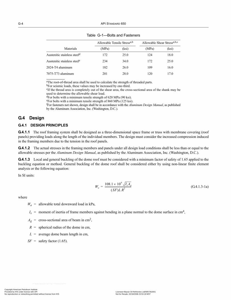
G-4 API STANDARD 650
Copyright AmProvided by No reproduc
G.4 DesignG.4.1 DESIGN PRINCIPLES
G.4.1.1 The roof framing system shall be designed as a three-dimensional space frame or truss with membrane covering (roofpanels) providing loads along the length of the individual members. The design must consider the increased compression inducedin the framing members due to the tension in the roof panels.
G.4.1.2 The actual stresses in the framing members and panels under all design load conditions shall be less than or equal to theallowable stresses per the Aluminum Design Manual, as published by the Aluminum Association, Inc. (Washington, D.C.).
G.4.1.3 Local and general buckling of the dome roof must be considered with a minimum factor of safety of 1.65 applied to thebuckling equation or method. General buckling of the dome roof shall be considered either by using non-linear finite elementanalysis or the following equation:
In SI units:
(G.4.1.3-1a)
where
Wa = allowable total downward load in kPa,
Ix = moment of inertia of frame members against bending in a plane normal to the dome surface in cm4,
Ag = cross-sectional area of beam in cm2,
R = spherical radius of the dome in cm,
L = average dome beam length in cm,
SF = safety factor (1.65).
Table G-1—Bolts and Fasteners
Materials
Allowable Tensile Stressa,b Allowable Shear Stressa,b,c
(MPa) (ksi) (MPa) (ksi)
Austenitic stainless steeld 172 25.0 124 18.0
Austenitic stainless steele 234 34.0 172 25.0
2024-T4 aluminum 182 26.0 109 16.0
7075-T73 aluminum 201 28.0 120 17.0
aThe root-of-thread area shall be used to calculate the strength of threaded parts.bFor seismic loads, these values may be increased by one-third.cIf the thread area is completely out of the shear area, the cross-sectional area of the shank may beused to determine the allowable shear load.dFor bolts with a minimum tensile strength of 620 MPa (90 ksi).eFor bolts with a minimum tensile strength of 860 MPa (125 ksi).fFor fasteners not shown, design shall be in accordance with the Aluminum Design Manual, as publishedby the Aluminum Association, Inc. (Washington, D.C.).
Wa108.1 106 IxAg
×
SF( )L R2------------------------------------------=
erican Petroleum Institute IHS under license with API Licensee=Bazan Oil Refineries Ltd/5957352001
Not for Resale, 02/18/2008 23:53:18 MSTtion or networking permitted without license from IHS
--``,,,,,,`,,`,`,`,``,,````,,``-`-`,,`,,`,`,,`---

WELDED STEEL TANKS FOR OIL STORAGE G-5
07
Copyright AmericaProvided by IHS uNo reproduction o
--``,,,,,
In US Customary units:
(G.4.1.3-1b)
where
Wa = allowable total downward load (lbf/ft2),
Ix = moment of inertia of frame members against bending in a plane normal to the dome surface (in.4),
Ag = cross-sectional area of beam (in.2),
R = spherical radius of the dome (in.),
L = average dome beam length (in.),
SF = safety factor (1.65).
G.4.1.4 The minimum net tension ring area (exclusive of bolt holes and member top flange protrusions) shall be determined perthe following formula:
In SI units:
(G.4.1.4-1a)
where
An = net area of tension beam, in cm2,
D = nominal tank diameter, in m,
η = number of dome supports,
θ = 1/2 the central angle of the dome or roof slope at the tank shell,
Ft = allowable stress of the tension ring, in kPa.
In US Customary units:
(G.4.1.4-1b)
where
An = net area of tension beam (in.2),
D = nominal tank diameter (ft),
η = number of dome supports,
θ = 1/2 the central angle of the dome or roof slope at the tank shell,
Ft = allowable stress of the tension ring (lbf/in.2).
In cases where the total dead load plus live load is greater than 1.34 kPa (28 lb/ft2), the above formula shall be multiplied by thefactor W/1.34 (or 28), where W = the total dead load plus live load for the dome.
Note: This formula does not include factors for bending stresses due to loads from the panel attached to the beam. These stresses must also beconsidered in the tension ring design, as per G.3.1.
Wa2258 106 IxAg
×
SF( )L R2-----------------------------------------=
An5.27D2
η θ 180η
---------⎝ ⎠⎛ ⎞Ftsintan
-------------------------------------------=
An11D2
η θ 180η
---------⎝ ⎠⎛ ⎞Ftsintan
-------------------------------------------=
,`,,`,`,`,``,,````,,``-`-`,,`,,`,`,,`---
n Petroleum Institute nder license with API Licensee=Bazan Oil Refineries Ltd/5957352001
Not for Resale, 02/18/2008 23:53:18 MSTr networking permitted without license from IHS

G-6 API STANDARD 650
07
Copyright AmProvided by No reproduc
G.4.2 DESIGN LOADS
Dome roofs shall be designed for the loads in 5.2.1, G.4.2, and G.4.3; and for the load combinations (a), (b), (c), (e), and (f) ofAppendix R.
G.4.2.1 Unbalanced Load
The design shall consider one-half of the uniform downward load required applied to one-half of the dome with only the deadload on the other half.
G.4.2.2 Wind Load
G.4.2.2.1 For dome structural design, the minimum wind load shall be the load resulting from a design wind speed of 190 km/h(120 mph) which imposes a velocity pressure of 1.48 kPa (31 lbf/ft2). The following pressure coefficients shall be used:
a. Windward quarter = –0.9b. Center half = –0.7c. Leeward quarter = –0.5
For domes designed for 3-sec gust wind speeds other than 190 km/h (120 mph), the wind load shall be multiplied by the fol-lowing:
In SI units:
(V/190)2 (G.4.2.2-1a)
In US Customary units:
(V/120)2 (G.4.2.2-1b)
where
V = wind speed (3-sec gust) in km/h (mph).
Note: The velocity pressure of 1.48 kPa (31 lbf/ft2) is based on ASCE 7-98, Category II, Exposure C, with an Importance Factor of 1.0.
G.4.2.2.2 See 5.11 for tank overturning stability.
G.4.2.3 Seismic Load
If the tank is designed for seismic loads, the roof shall be designed for a horizontal seismic force determined as follows:
F = 0.6 ZIWr (G.4.2.3-1)
where
F = horizontal seismic force.
Z, I, and Wr are as defined in Appendix E. The force shall be uniformly applied over the surface of the roof.
G.4.2.4 Panel Loads
G.4.2.4.1 Roof panels shall be of one-piece aluminum sheet (except for skylights as allowed by G.8.4) and shall be designed tosupport a uniform load of 3 kPa (60 lbf/ft2) over the full area of the panel without sustaining permanent distortion.
G.4.2.4.2 The roof shall be designed to support two concentrated loads 1100 N (250 lbf), each distributed over two separate0.1 m2 (1 ft2) areas of any panel.
G.4.2.4.3 The loads specified in G.4.2.4.1 and G.4.2.4.2 shall not be considered to act simultaneously or in combination withany other loads.
--``,,,,,,`,,`,`,`,``,,````,,``-`-`,,`,,`,`,,`---
erican Petroleum Institute IHS under license with API Licensee=Bazan Oil Refineries Ltd/5957352001
Not for Resale, 02/18/2008 23:53:18 MSTtion or networking permitted without license from IHS

WELDED STEEL TANKS FOR OIL STORAGE G-7
•
•
•
•
Copyright AmericaProvided by IHS uNo reproduction o
--``,,,,,,`,,`,`,`,``,,````,,``-`-`,,`,,`,`,,`---
G.4.3 INTERNAL PRESSURE
Unless otherwise specified by the Purchaser, the internal design pressure shall not exceed the weight of the roof. In no case shallthe maximum design pressure exceed 2.2 kPa (9 in.) water column. When the design pressure, Pmax, for a tank with an aluminumdome roof is being calculated, the weight of the roof, including structure, shall be added to the weight of the shell in the W term inF.4.2, and th shall be taken as zero.
G.5 Roof AttachmentG.5.1 LOAD TRANSFER
Structural supports for the roof shall be bolted or welded to the tank. To preclude overloading of the shell, the number of attach-ment points shall be determined by the roof manufacturer in consultation with the tank Manufacturer. The attachment detail shallbe suitable to transfer all roof loads to the tank shell and keep local stresses within allowable limits.
G.5.2 ROOF SUPPORTS
The roof attachment points may incorporate a slide bearing with low-friction bearing pads to minimize the horizontal radialforces transferred to the tank. As an alternative, the roof may be attached directly to the tank, and the top of the tank analyzedand designed to sustain the horizontal thrust transferred from the roof, including that from differential thermal expansion andcontraction.
G.5.3 SEPARATION OF CARBON STEEL AND ALUMINUM
Unless another method is specified by the Purchaser, aluminum shall be isolated from carbon steel by an austenitic stainless steelspacer or an elastomeric isolator bearing pad.
G.5.4 ELECTRICAL GROUNDING
The aluminum dome roof shall be electrically interconnected with and bonded to the steel tank shell or rim. As a minimum, stain-less steel cable conductors 3 mm (1/8 in.) in diameter shall be installed at every third support point. The choice of cable shall takeinto account strength, corrosion resistance, conductivity, joint reliability, flexibility, and service life.
G.6 Physical CharacteristicsG.6.1 SIZES
An aluminum dome roof may be used on any size tank erected in accordance with this Standard.
G.6.2 DOME RADIUS
The maximum dome radius shall be 1.2 times the diameter of the tank. The minimum dome radius shall be 0.7 times the diameterof the tank unless otherwise specified by the Purchaser.
G.7 Platforms, Walkways, and HandrailsPlatforms, walkways, and handrails shall conform to 3.8.10 except that the maximum concentrated load on walkways or stair-ways supported by the roof structure shall be 4450 N (1000 lbf). When walkways are specified to go across the exterior of the roof(to the apex, for example), stairways shall be provided on portions of walkways whose slope is greater than 20 degrees. Walkwaysand stairways may be curved or straight segments.
G.8 AppurtenancesG.8.1 ROOF HATCHES
If roof hatches are required, each hatch shall be furnished with a curb 100 mm (4 in.) or higher and a positive latching device tohold the hatch in the open position. The minimum size of opening shall not be less than 600 mm (24 in.). The axis of the openingmay be perpendicular to the slope of the roof, but the minimum clearance projected on a horizontal plane shall be 500 mm(20 in.).
n Petroleum Institute nder license with API Licensee=Bazan Oil Refineries Ltd/5957352001
Not for Resale, 02/18/2008 23:53:18 MSTr networking permitted without license from IHS

G-8 API STANDARD 650
•07
•
Copyright AmProvided by No reproduc
G.8.2 ROOF NOZZLES AND GAUGE HATCHES
Roof nozzles and gauge hatches shall be flanged at the base and bolted to the roof panels with an aluminum reinforcing plate onthe underside of the panels. The axis of a nozzle or gauge hatch shall be vertical. If the nozzle is used for venting purposes, it shallnot project below the underside of the roof panel. Aluminum or stainless steel flanges may be bolted directly to the roof panel,with the joint caulked with sealant. Steel flanges shall be separated from the aluminum panel by a gasket (see Figure G-2 for atypical nozzle detail).
G.8.3 SKYLIGHTS
G.8.3.1 If skylights are specified by the Purchaser, each skylight shall be furnished with a curb 100 mm (4 in.) or higherand shall be designed for the live and wind loads specified in G.4.2.5. The Purchaser shall specify the total skylight area to beprovided.
G.8.3.2 When skylights are specified for tanks without floating roofs or for floating roof tanks which are sealed and gas-blan-keted (not provided with circulation venting per H.5.2.2.1 and H.5.2.2.2), the Purchaser shall consider skylight material compati-bility with exposure to elevated concentrations of the stored product.
G.9 Sealing at the ShellThe roof need not be sealed to the tank shell unless specified by the Purchaser or required to contain internal pressure. The bottom ofthe flashing shall extend at least 50 mm (2 in.) below the top of the tank. Corrosion-resistant coarse-mesh screen (13 mm [1/2 in.]openings) shall be provided to prevent the entrance of birds.
Figure G-2—Typical Roof Nozzle
Flanged base
Through-fastener
Dome panel
Reinforcing plate (Typical)
Nozzle
--``,,,,,,`,,`,`,`,``,,````,,``-`-`,,`,,`,`,,`---
erican Petroleum Institute IHS under license with API Licensee=Bazan Oil Refineries Ltd/5957352001
Not for Resale, 02/18/2008 23:53:18 MSTtion or networking permitted without license from IHS
WELDED STEEL TANKS FOR OIL STORAGE G-9
•
•
07
•
Copyright AmericaProvided by IHS uNo reproduction o
G.10 TestingG.10.1 LEAK TESTING
G.10.1.1 After completion, the roof seams shall be leak tested by spraying the outside of the seams with water from a hose witha minimum static head pressure 350 kPa (50 lbf/in.2) gauge at the nozzle. Because of possible corrosive effects, considerationshall be given to the quality of the water used and the duration of the test. Potable water shall be used unless otherwise specified.The water shall not be sprayed directly on roof vents. Any water on the inside of the roof shall constitute evidence of leakage.
G.10.1.2 Where gas-tight roofs are required, leak testing may be accomplished in accordance with F.4.4 or F.7.6 or by anothermeans acceptable to the roof manufacturer and the Purchaser.
G.10.1.3 Any leaks discovered during testing shall be sealed, and the roof shall be retested until all leaks are sealed.
G.11 Fabrication and ErectionG.11.1 GENERAL
The dome contractor shall perform the work described in this appendix using qualified supervisors who are skilled and experi-enced in the fabrication and erection of aluminum structures.
G.11.2 FABRICATION
All roof parts shall be prefabricated for field assembly. Fabrication procedures shall be in accordance with Section 6 of the Alumi-num Design Manual. All structural shapes used to make the roof shall be punched or drilled before any shop coating is applied.
G.11.3 WELDING
The design and fabrication of welded aluminum parts shall be in accordance with the Aluminum Design Manual: Specificationsfor Aluminum Structures and AWS D1.2. All aluminum structural welds and components joined by welding shall be visuallyinspected and tested by dye-penetrant examination in accordance with Section 5, Part D, of AWS D1.2. All structural welding ofaluminum shall be performed before the dome is erected in the field. A full set of satisfactory examination records shall be deliv-ered to the owner before field erection.
G.11.4 SHIPPING AND HANDLING
Materials shall be handled, shipped, and stored in a manner that does not damage the surface of aluminum or the surface coatingof steel.
G.11.5 ERECTION
The erection supervisor shall be experienced in the construction of aluminum dome roofs and shall follow the Manufacturer’sinstructions and drawings furnished for that purpose.
G.11.6 WORKMANSHIP
To minimize internal stresses on the structure when fasteners are tightened, the roof shall be installed on supports that are in goodhorizontal alignment. The components of the structure shall be erected with precise fit and alignment. Field cutting and trimming,relocation of holes, or the application of force to the parts to achieve fit-up is not acceptable.
--``,,,,,,`,,`,`,`,``,,````,,``-`-`,,`,,`,`,,`---
n Petroleum Institute nder license with API Licensee=Bazan Oil Refineries Ltd/5957352001
Not for Resale, 02/18/2008 23:53:18 MSTr networking permitted without license from IHS

Copyright AmProvided by No reproduc
--``,,,,,,`,,`,`,`,``,,````,,``-`-`,,`,,`,`,,`---
erican Petroleum Institute IHS under license with API Licensee=Bazan Oil Refineries Ltd/5957352001
Not for Resale, 02/18/2008 23:53:18 MSTtion or networking permitted without license from IHS

•
• 07
•
07
Copyright AmericaProvided by IHS uNo reproduction o
--``,,,,,,`,,`,`,`,``,,````,,``-`-`,,`,,`,`,,`---
APPENDIX H—INTERNAL FLOATING ROOFS
H.1 ScopeH.1.1 This appendix provides minimum requirements that apply to a tank with an internal floating roof and a fixed roof atthe top of the tank shell, and to the tank appurtenances. This appendix is intended to limit only those factors that affect thesafety and durability of the installation and that are considered to be consistent with the quality and safety requirements ofthis Standard. Types of internal floating roofs (listed under H.2) and materials (listed under H.3) are provided as a basicguide and shall not be considered to restrict the Purchaser option of employing other commonly accepted or alternativedesigns, as long as all design loading is documented to meet the minimum requirements herein, and all other criteria aremet (except alternative materials and thicknesses as permitted by H.3.1). The requirements apply to the internal floatingroof of a new tank and may be applied to an existing fixed-roof tank. Section 5.10 of this Standard is applicable, except asmodified in this appendix.
H.1.2 The Purchaser is required to provide all applicable jurisdictional requirements that apply to internal floating roofs (see 1.3).
H.1.3 See Appendix W for bid requirements pertaining to internal floating roofs.
H.2 Types of Internal Floating RoofsH.2.1 The internal floating roof type shall be selected by the Purchaser after consideration of both proposed and future productservice, operating conditions, maintenance requirements, regulatory compliance, service life expectancy, ambient temperature,maximum design temperature, product vapor pressure, corrosion conditions and other compatibility factors. Other operating con-ditions requiring consideration include (but are not limited to) anticipated pumping rates, roof landing cycles, and the potential forturbulence resulting from upsets, such as vapor slugs injected into the tank. Safety and risk factors associated with the roof typesshall also be evaluated21. The type of roof, which shall be designated by the Purchaser on the Data Sheet, Line 30, shall be one ofthe types described in H.2.2.
H.2.2 The following types of internal floating roofs are described in this appendix:
a. Metallic pan internal floating roofs22,23,24 have a peripheral rim above the liquid for buoyancy. These roofs are in full contactwith the liquid surface and are typically constructed of steel.b. Metallic open-top bulk-headed internal floating roofs23,24 have peripheral open-top bulk-headed compartments for buoyancy.Distributed open-top bulk-headed compartments shall be used as required. These roofs are in full contact with the liquid surfaceand are typically constructed of steel.c. Metallic pontoon internal floating roofs have peripheral closed-top bulk-headed compartments for buoyancy. Distributedclosed-top bulk-headed compartments shall be used as required. These roofs are in full contact with the liquid surface and are typ-ically constructed of steel.d. Metallic double-deck internal floating roofs have continuous closed top and bottom decks, which contain bulk-headed com-partments for buoyancy. These roofs are in full contact with the liquid surface and are typically constructed of steel.e. Metallic internal floating roofs on floats have their deck above the liquid, supported by closed pontoon compartments forbuoyancy. These roof decks are not in full contact with the liquid surface and are typically constructed of aluminum alloys orstainless steel.
21Internal floating roof tanks generally have reduced fire risk, and the use of fixed fire suppression systems is often not mandatory. Various inter-nal floating roof materials will have unique flammability characteristics, melting points and weights (perhaps with reduced buoyancy beingrequired). If fire suppression systems are used, certain roof types need to be evaluated for full surface protection. NFPA 11 Standard for Low-Expansion Foam can provide guidance for this evaluation.22The Purchaser is cautioned that this design does not have multiple flotation compartments necessary to meet the requirements of H.4.2.1.3. 23These designs contain no closed buoyancy compartments, and are subject to flooding during sloshing or during application of fire-fightingfoam/water solution. Also, without bracing of the rim being provided by the pontoon top plate, design to resist buckling of the rim must beevaluated.24If the floating roof is a) a metallic pan roof with or without bulkheads, or b) a non-metallic roof with or without closed buoyancy compart-ments, then the tank is considered a fixed-roof tank (i.e., having no internal floating roof) for the requirements of NFPA 30. See NFPA 30 forspacing restrictions on floating roof tanks.
H-1
n Petroleum Institute nder license with API Licensee=Bazan Oil Refineries Ltd/5957352001
Not for Resale, 02/18/2008 23:53:18 MSTr networking permitted without license from IHS

H-2 API STANDARD 650
•07
•
07
•
Copyright AmProvided by No reproduc
--``,,,,,,`,,`,`,`,``,,````,,``-`-`,,`,,`,`,,`---
f. Metallic sandwich-panel/composite internal floating roofs have metallic or composite material panel modules for buoyancycompartments. Panel modules may include a honeycomb or closed cell foam core; however, cell walls within the panel moduleare not considered “compartments” for purposes of inspection and design buoyancy requirements (see H.4.1.7 and H.4.2.1)25.These roofs are in full contact with the liquid surface and are typically constructed of aluminum alloys or Purchaser approvedcomposite materials.24
g. Hybrid internal floating roofs shall, upon agreement between the Purchaser and the manufacturer, be a design combination ofroof types described in H.2.2.b and H.2.2.c, having bulkhead compartments with closed-top perimeter pontoon and open-top cen-ter compartments for buoyancy. These roofs are in full contact with the liquid surface and are typically constructed of steel.h. Other roof materials or designs if specified and described in detail by the Purchaser on the Data Sheet.
H.3 MaterialH.3.1 SELECTION
Internal floating roof materials shall be selected by the Purchaser after consideration of items listed under H.2.1. The manufac-turer shall submit a complete material specification in his proposal. The choice of materials should be governed by compatibilitywith the specified liquid. Material produced to specifications other than those listed in this appendix (alternative materials) maybe used. Material shall be certified to meet all the requirements of a material specification listed in this appendix, and approved bythe Purchaser or shall comply with requirements as specified by the Purchaser. When specified by the Purchaser, a corrosionallowance shall be added to the minimum nominal thickness indicated below. The “nominal thickness” is the purchased thicknesswith allowance for the permissible mill tolerance.
H.3.2 STEEL
Steel shall conform to the requirements of Section 4 of this Standard. Steel in contact with vapor or liquid shall be 5 mm (3/16 in.)minimum nominal thickness. Other steel shall be 2.5 mm (0.094 in.) minimum nominal thickness.
H.3.3 ALUMINUM
Aluminum shall conform to the requirements of Section 2 of ASME B96.1. Aluminum skin shall be 0.51 mm (0.020 in.) mini-mum nominal thickness. Aluminum floats shall be 1.3 mm (0.050 in.) minimum nominal thickness. For a sandwich panel flota-tion unit, core material shall be at least 25 mm (1.0 in.) thick, and metallic skin (except carbon steel) shall be 0.41 mm (0.016 in.)minimum nominal thickness.
H.3.4 STAINLESS STEEL
Stainless steel shall conform to the requirements of ASTM A 240/A 240M (austenitic type only). Stainless steel skin shall be0.46 mm (0.018 in.) minimum nominal thickness. Stainless steel floats shall be 1.2 mm (0.048 in.) minimum nominal thickness.
H.4 Requirements for All TypesH.4.1 GENERAL
H.4.1.1 An internal floating roof and its accessories shall be designed and constructed to allow the roof to operate throughoutits normal travel without manual attention and without damage to any part of the fixed roof, the internal floating roof, internalfloating roof seals (except for normal wear), the tank, or their appurtenances. The internal floating roof and seals shall be designedto operate in a tank constructed within the dimensional limits defined in 7.5 of this Standard.
H.4.1.2 The internal floating roof shall be designed and built to float and rest in a uniform horizontal plane (no drainage sloperequired).
H.4.1.3 All seams in the internal floating roof that are exposed to product vapor or liquid shall be vapor-tight in accordancewith H.4.3.1.
25A single inspection opening per panel module is permitted, regardless of core material; however, core materials producing enclosed spaceswithin a module may result in undetectable combustible gas in areas isolated from the inspection opening. Design buoyancy shall be based onthe loss of any two full panel modules (not cells within modules).
•
erican Petroleum Institute IHS under license with API Licensee=Bazan Oil Refineries Ltd/5957352001
Not for Resale, 02/18/2008 23:53:18 MSTtion or networking permitted without license from IHS

WELDED STEEL TANKS FOR OIL STORAGE H-3
•
07
•
•
•
•
•
07
•
Copyright AmericaProvided by IHS uNo reproduction o
H.4.1.4 A vapor-tight rim (or skirt), extending at least 150 mm (6 in.) above the liquid at the design flotation level, shall be pro-vided around both the internal floating roof periphery and around all internal floating roof penetrations (columns, ladders, stillingwells, manways, open deck drains and other roof openings).
H.4.1.5 The non-contact type (see H.2.2e) internal floating roof shall have a vapor-tight rim (or skirt), extending at least100 mm (4 in.) into the liquid at the design flotation level, around both the internal floating roof periphery and around all internalfloating roof penetrations (columns, ladders, stilling wells, manways, open deck drains and other roof openings), with the excep-tion of penetrations for pressure-vacuum (bleeder) vents (per H.5.2.1).
H.4.1.6 All conductive parts of the internal floating roof shall be electrically interconnected and bonded to the outer tank struc-ture. This shall be accomplished by electric bonding shunts in the seal area (a minimum of four, uniformly distributed) or flexiblemulti-strand cables from the external tank roof to the internal floating roof (a minimum of two, uniformly distributed). The choiceof bonding devices shall be specified by the Purchaser on the Data Sheet, Line 32, considering strength, corrosion resistance, jointreliability, flexibility, and service life. All movable cover accessories (hatches, manholes, pressure relief devices, and other open-ings) on the internal floating roof shall be electrically bonded to the internal floating roof to prevent static electricity sparkingwhen they are opened.
H.4.1.7 Each closed flotation compartment shall be capable of being field-inspected for the presence of combustible gas.Inspection openings shall be located above the liquid level and closed compartments shall be capable of being resealed in the fieldafter periodic inspection (to prevent liquid or vapor entry). Closed-top compartments (types H.2.2c, d, and g) shall be accessiblefrom the top of the internal floating roof and provided with a secured and gasketed manhole for visual internal inspection and themanhole cover shall be provided with a suitable vent. The top edge of the manhole shall extend a minimum of 25 mm (1 in.)above the top of the pontoon rim/skirt. With agreement by the Purchaser, type H.2.2c, d, and g floating roofs 6 m (20 ft) in diam-eter or less may be provided with an inspection port in place of a manhole. The inspection ports must meet the sealing, securingand extension requirements listed here for manholes in internal floating roof closed compartments.
H.4.1.8 All closed flotation compartments shall be seal welded to prevent liquid or vapor entry, unless otherwise specified bythe Purchaser. For pontoon, double-deck and hybrid internal floating roofs (types H.2.2c, d, and g), each bulkhead in a closed flo-tation compartment shall also be provided with a continuous seal weld all around so that the bulkhead is liquid and vapor-tight.
H.4.1.9 For metallic/composite sandwich-panel roofs (type H.2.2f), if the use of adhesives is allowed by the Purchaser (perH.4.3.4) to seal the flotation panels (in lieu of welding), all exposed adhesives shall be compatible with the product service andflotation test water (Purchaser shall consider future product service, the hydrostatic test condition, and design condition changesto specify adhesive compatibility.)
H.4.1.10 When specified by the Purchaser for deck surfaces above the liquid level, deck drains shall be provided to return anyspillage or condensate to the product. Such drains shall close automatically or extend at least 100 mm (4 in.) into the product tominimize vapor loss.
H.4.1.11 Internal floating roofs classified as full-contact types (see H.2.2) shall be designed to minimize trapped vapor spacebeneath the internal floating roof.
H.4.2 INTERNAL FLOATING ROOF DESIGN
H.4.2.1 Buoyancy Requirements
H.4.2.1.1 All internal floating roof design calculations shall be based on the lower of the product specific gravity or 0.7 (toallow for operation in a range of hydrocarbon service), regardless of any higher specific gravity that might be specified by thePurchaser.
H.4.2.1.2 All internal floating roofs shall include buoyancy required to support at least twice its dead weight (including theweight of the flotation compartments, seal and all other floating roof and attached components), plus additional buoyancy to offsetthe calculated friction exerted by peripheral and penetration seals during filling.
H.4.2.1.3 All internal floating roofs with multiple flotation compartments shall be capable of floating without additional dam-age after any two compartments are punctured and flooded. Designs which employ an open center deck in contact with the liquid(types H.2.2b, c, and g) shall be capable of floating without additional damage after any two compartments and the center deckare punctured and flooded. With agreement by the Purchaser, any floating roof 6 m (20 ft) in diameter or less with multiple flota-
--``,,,,,,`,,`,`,`,``,,````,,``-`-`,,`,,`,`,,`---
n Petroleum Institute nder license with API Licensee=Bazan Oil Refineries Ltd/5957352001
Not for Resale, 02/18/2008 23:53:18 MSTr networking permitted without license from IHS

H-4 API STANDARD 650
•
07
•
••
07
•
07
Copyright AmProvided by No reproduc
,,,,,,`,,`,`,`,``,,````,,``-`-`,,`,,`,`,,`---
tion compartments may be designed to be capable of floating without additional damage after any one compartment is puncturedand flooded.
H.4.2.2 Design Loads
H.4.2.2.1 The internal floating roof shall be designed to meet the requirements of H.4.2.1.3 and to safely support at least twomen (2.2 kN [500 lbf] over 0.1 m2 [1 ft2]) walking anywhere on the roof while it is floating or resting on its supports without dam-aging the floating roof and without allowing product on the roof. If specified by the Purchaser, the concentrated load design crite-ria may be modified for roofs less than 9 m (30 ft) diameter (where internal floating roofs may become unstable), to account foraccess needs, and expected concentrated live loads.
H.4.2.2.2 Internal floating roof supports and deck structural attachments (such as reinforcing pads and pontoon end gussets)shall be designed to support the full dead load of the internal floating roof (including all components, such as seals and accesso-ries) plus a uniform live load of 0.6 kPa (12.5 lbf/ft2) over the internal floating roof deck surface while the internal floating roof isresting on its supports. This uniform live load may be reduced to 0.24 kPa (5 lbf/ft2) if the floating roof is equipped with operabledrains or other means of automatically preventing an accumulation of liquid. Consideration shall also be made for non-uniformsupport settlement/load distribution, based on anticipated conditions specified by the Purchaser.
H.4.2.3 Other Design Requirements
H.4.2.3.1 Aluminum load carrying members, assemblies and connections shall comply with the design requirements of the lat-est edition of the Aluminum Design Manual.
H.4.2.3.2 Steel structural components shall be proportioned so that the maximum stresses shall not exceed the limitations spec-ified in the latest edition of the Manual of Steel Construction, Allowable Stress Design, as published by the American Institute ofSteel Construction (Chicago, IL). For other steel components, the allowable stress and stability requirements shall be jointlyestablished by the Purchaser and the manufacturer, as part of the inquiry. Alternatively, a proof test (simulating the conditions ofH.4.2) may be performed on the roof or on one of similar design.
H.4.3 JOINT DESIGN
H.4.3.1 All seams in the floating roof exposed directly to product vapor or liquid shall be welded, bolted, screwed, riveted,clamped, or sealed and checked for vapor-tightness per H.6.2.
H.4.3.2 Welded joints between stainless steel members and welded joints between carbon steel members shall conform to 5.1of this Standard. Welded joints between aluminum members shall conform to 3.1 of ASME B96.1.
H.4.3.2.1 Single-welded butt joints without backing are acceptable for flotation units where one side is inaccessible.
H.4.3.2.2 The thickness of fillet welds on material less than 5 mm (3/16 in.) thick shall not be less than that of the thinner mem-ber of the joint.
H.4.3.3 Bolted, threaded, and riveted joints are acceptable when mutually agreed upon by the Purchaser and the manufacturer.
H.4.3.3.1 Only austenitic type stainless steel hardware shall be used to join aluminum and/or stainless steel components to eachother or to carbon steel. Where acceptable to the Purchaser and the manufacturer, aluminum hardware may be used to join alumi-num components. Aluminum shall be isolated from carbon steel by an austenitic stainless steel spacer, an elastomeric pad, orequivalent protection. The use of plated fasteners shall be permitted only when connecting steel components, if specified by thePurchaser.
H.4.3.4 Use of any joint sealing compound, insulating material, polymer, elastomer or adhesive must be pre-approved by thePurchaser. The joining procedure along with test results demonstrating the properties required by this paragraph shall bedescribed completely. Where such joints are permitted, any joint sealing compound, insulating material, elastomeric or adhesiveshall be compatible with the product stored, specified service conditions, and with materials joined. Resulting joints shall beequivalent in serviceability (with the basic floating roof components), of a size and strength that will accept the roof design loadswithout failure or leakage, and shall have an expected life equal to the service life of the roof. Any non-metallic component shallbe selected and fabricated to preclude absorption (under design conditions specified and permitted by this Standard) of hydrocar-bons, hydro-test water and specified product to be stored.
erican Petroleum Institute IHS under license with API Licensee=Bazan Oil Refineries Ltd/5957352001
Not for Resale, 02/18/2008 23:53:18 MSTtion or networking permitted without license from IHS
--``
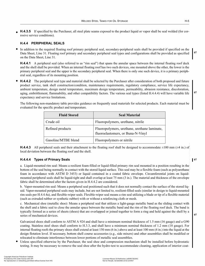
WELDED STEEL TANKS FOR OIL STORAGE H-5
•
•07
•
07
07
07
•
Copyright AmericaProvided by IHS uNo reproduction o
H.4.3.5 If specified by the Purchaser, all steel plate seams exposed to the product liquid or vapor shall be seal welded (for cor-rosive service conditions).
H.4.4 PERIPHERAL SEALS
In addition to the required floating roof primary peripheral seal, secondary peripheral seals shall be provided if specified on theData Sheet, Line 31. Floating roof primary and secondary peripheral seal types and configurations shall be provided as specifiedon the Data Sheet, Line 31.
H.4.4.1 A peripheral seal (also referred to as “rim seal”) that spans the annular space between the internal floating roof deckand the shell shall be provided. When an internal floating roof has two such devices, one mounted above the other, the lower is theprimary peripheral seal and the upper is the secondary peripheral seal. When there is only one such device, it is a primary periph-eral seal, regardless of its mounting position.
H.4.4.2 The peripheral seal type and material shall be selected by the Purchaser after consideration of both proposed and futureproduct service, tank shell construction/condition, maintenance requirements, regulatory compliance, service life expectancy,ambient temperature, design metal temperature, maximum design temperature, permeability, abrasion resistance, discoloration,aging, embrittlement, flammability, and other compatibility factors. The various seal types (listed H.4.4.4) will have variable lifeexpectancy and service limitations.
The following non-mandatory table provides guidance on frequently used materials for selected products. Each material must beevaluated for the specific product and temperature.
H.4.4.3 All peripheral seals and their attachment to the floating roof shall be designed to accommodate ±100 mm (±4 in.) oflocal deviation between the floating roof and the shell.
H.4.4.4 Types of Primary Seals
a. Liquid-mounted rim seal: Means a resilient foam-filled or liquid-filled primary rim seal mounted in a position resulting in thebottom of the seal being normally in contact with the stored liquid surface. This seal may be a flexible foam (such as polyurethanefoam in accordance with ASTM D 3453) or liquid contained in a coated fabric envelope. Circumferential joints on liquid-mounted peripheral seals shall be liquid-tight and shall overlap at least 75 mm (3 in.). The material and thickness of the envelopefabric shall be determined after the factors given in H.4.4.2 are considered.b. Vapor-mounted rim seal: Means a peripheral seal positioned such that it does not normally contact the surface of the stored liq-uid. Vapor-mounted peripheral seals may include, but are not limited to, resilient-filled seals (similar in design to liquid-mountedrim seals per H.4.4.4a), and flexible-wiper seals. Flexible-wiper seal means a rim seal utilizing a blade or tip of a flexible material(such as extruded rubber or synthetic rubber) with or without a reinforcing cloth or mesh.c. Mechanical shoe (metallic shoe): Means a peripheral seal that utilizes a light-gauge metallic band as the sliding contact withthe shell and a fabric seal to close the annular space between the metallic band and the rim of the floating roof deck. The band istypically formed as a series of sheets (shoes) that are overlapped or joined together to form a ring and held against the shell by aseries of mechanical devices.
Galvanized shoes shall conform to ASTM A 924 and shall have a minimum nominal thickness of 1.5 mm (16 gauge) and a G90coating. Stainless steel shoes shall conform to H.3.3, and shall have a minimum nominal thickness of 1.2 mm (18 gauge). Forinternal floating roofs the primary shoes shall extend at least 150 mm (6 in.) above and at least 100 mm (4 in.) into the liquid at thedesign flotation level. If necessary, bottom shell course accessories (e.g., side mixers) and other assemblies shall be modified orrelocated to eliminate interference between lower portions of metallic seal assemblies.Unless specified otherwise by the Purchaser, the seal shoe and compression mechanism shall be installed before hydrostatictesting. It may be necessary to remove the seal shoe after the hydro-test to accommodate cleaning, application of interior coat-
Fluid Stored Seal Material
Crude oil Fluoropolymers, urethane, nitrile
Refined products Fluoropolymers, urethane, urethane laminate, fluoroelastomers, or Buna-N-Vinyl
Gasoline/MTBE blend Fluoropolymers or nitrile
--``,,,,,,`,,`,`,`,``,,````,,``-`-`,,`,,`,`,,`---
n Petroleum Institute nder license with API Licensee=Bazan Oil Refineries Ltd/5957352001
Not for Resale, 02/18/2008 23:53:18 MSTr networking permitted without license from IHS

H-6 API STANDARD 650
07
••
•
07
•07
Copyright AmProvided by No reproduc
ings, or any situation where the installed shoe might interfere with the process. The fabric seal may be installed after thehydrostatic testing.
H.4.4.5 The specific requirements for all floating roof peripheral seals are:
1. All fasteners and washers for installation of seal joints, including fabric seal joints, shall be austenitic stainless steel. (Seerestrictions on contact between galvanizing and stainless steel in S.2.1.3.)2. The seals shall be designed for a temperature range extending from design metal temperature less 8°C (15°F) to the maxi-mum operating temperature.
3. Lengths of seal sections shall be as long as practical. No holes or openings shall be permitted in the completed seal. Theseal material may be fabricated in sections resulting in seams, but any such seam shall be joined or otherwise held tightlytogether along the entire seam. For peripheral seals that use a fabric material to effect the seal, the requirement in the precedingsentence applies only to the fabric and not to any support devises. An adequate but minimum number of expansion joints shallbe provided.
4. Provisions shall be made to prevent damage to the seal due to any overflow openings in the shell.
5. Rough spots on the shell that could damage the seal assembly shall be ground smooth. See H.6.1.
6. All metallic components shall be electrically bonded. See H.4.1.6 or C.3.1.6 for electrical bonding requirements.
H.4.4.6 If wax scrapers are specified on the Data Sheet, Line 31, they shall be located such that the scraping action occursbelow the liquid surface. Design of wax scrapers shall not interfere with bottom shell course accessories.
H.4.5 ROOF PENETRATIONS
Columns, ladders, and other rigid vertical appurtenances that penetrate the deck shall be provided with a seal that will permit alocal deviation of ±125 mm (±5 in.). Appurtenances shall be plumb within a tolerance of ±75 mm (±3 in.).
H.4.6 ROOF SUPPORTS
H.4.6.1 The floating roof shall be provided with adjustable supports, unless the Purchaser specifies fixed supports.
H.4.6.2 Unless specified otherwise, the height of the floating roof shall be adjustable to two positions with the tank in service.The design of the supports shall prevent damage to the fixed roof and floating roof when the tank is in an overflow condition.
H.4.6.3 The Purchaser shall specify clearance requirements to establish the low (operating) and high (maintenance) levels ofthe roof supports. The low roof position shall be the lowest permitted by the internal components of the tank including shell noz-zles with internal projections. If specified, a single position support height shall be based on the Purchaser-specified clearancedimension. The Purchaser shall provide data to enable the manufacturer to ensure that all tank appurtenances (such as mixers,interior piping, and fill nozzles) are cleared by the roof in its lowest position. In addition to fitting elevations, such data shallinclude minimum mixer operation level and low level alarm settings (if applicable). If not specified otherwise by the Purchaser,the following apply:
H.4.6.3.1 The high roof position shall provide a 2-m (78-in.) minimum clearance throughout the bottom, between the roof andthe tank bottom.
H.4.6.3.2 Where propeller-type mixers are used, the support legs shall provide a minimum clearance of 75 mm (3 in.) from theunderside of the internal floating roof (or roof notch) to the tip of the mixer propeller.
H.4.6.4 Support attachments in the deck area shall be designed to prevent failure at the point of attachment. On the bottom ofthe steel welded deck plates (used on types H.2.2a, b, c, d, and g), where flexure is anticipated adjacent to supports or other rela-tively rigid members, full-fillet welds not less than 50 mm (2 in.) long on 250 mm (10 in.) centers shall be used on any plate lapsthat occur within 300 mm (12 in.) of any such support or member.
H.4.6.5 Supports shall be fabricated from pipe, unless cable or another type is specified on the Data Sheet, Line 34 andapproved by the Purchaser. Supports fabricated from pipe shall be notched or otherwise constructed at the bottom to provide com-plete liquid drainage. Cable supports shall be adjustable externally and shall not have an open penetration at the floating roof sur-face. Fixed roofs shall be designed or verified suitable for cable support loads, when used, per agreement between the Purchaserand tank/roof Manufacturers.
--``,,,,,,`,,`,`,`,``,,````,,``-`-`,,`,,`,`,,`---
erican Petroleum Institute IHS under license with API Licensee=Bazan Oil Refineries Ltd/5957352001
Not for Resale, 02/18/2008 23:53:18 MSTtion or networking permitted without license from IHS

WELDED STEEL TANKS FOR OIL STORAGE H-7
•
•
•
•07
•
07
•
•
07
•
Copyright AmericaProvided by IHS uNo reproduction o
H.4.6.6 Steel pads or other means shall be used to distribute the loads on the bottom of the tank and provide a wear surface.With the Purchaser’s approval, pads may be omitted if the tank bottom will support the live load plus the dead load of the floatingroof. If pads are used, they shall be continuously welded to the tank bottom.
H.4.6.7 Aluminum supports shall be isolated from carbon steel by an austenitic stainless steel spacer, an elastomeric bearingpad, or equivalent protection, unless specified otherwise by the Purchaser.
H.4.6.8 Special protective measures (corrosion allowance, material selection, coatings) are to be evaluated for supports thatinterface with stratified product bottoms, which may include corrosive contaminant combinations not found in the normal prod-uct. The Purchaser shall specify if any protective measures are required.
H.4.6.9 For tanks with internal coatings, the Purchaser shall specify on Line 23 of the Data Sheet any special requirements forminimizing corrosion where the leg contacts the tank bottom, such as a flat plate or bull nose on the leg base, a thicker base plate,or other means.
H.5 Openings and AppurtenancesH.5.1 LADDER
H.5.1.1 The tank interior is considered a confined space environment with restricted access (see API RP 2026). If specified bythe Purchaser, the tank shall be supplied with a ladder for internal floating roof deck access. If a ladder is not supplied and thefloating roof is not steel, a ladder landing pad shall be provided on the floating roof.
H.5.1.2 The ladder shall be designed to allow for the full travel of the internal floating roof, regardless of any settling of theroof supports.
H.5.1.3 The ladder shall be installed within a fixed-roof manhole, per H.5.5.1.
H.5.1.4 If a level-gauge stilling well is provided, the well may form one or both legs of the ladder, as specified by thePurchaser.
H.5.1.5 The ladder shall not be attached to the tank bottom unless provision is made for vertical movement at the upperconnection.
H.5.2 VENTS
H.5.2.1 Internal Floating Roof Pressure-Vacuum (Bleeder) Vents
Vents suitable to prevent overstressing of the roof deck or seal membrane shall be provided on the floating roof. These vents shallbe adequate to evacuate air and gases from underneath the roof such that the internal floating roof is not lifted from resting on itssupports during filling operations, until floating on the stored liquid. The vents shall also be adequate to release any vacuum gen-erated underneath the roof after it settles on its supports during emptying operations. The Purchaser shall specify filling and emp-tying rates so that the manufacturer can size the vents. Leg- or float-activated vents are required unless the Purchaser specifiesotherwise, such as pressure vacuum vents, and the associated design conditions (see Line 33 of the Data Sheet). Leg activatedvents shall be adjustable as required per H.4.6. Leg-activated vents shall be designed to open automatically when the roof lowersto 150 mm (6 in.) above its lowest operating position and to close automatically when the roof raises more than 150 mm (6 in.)above its lowest position. Float-activated vents shall be designed to remain closed while the roof is floating.
H.5.2.2 Tank Circulation Vents
H.5.2.2.1 Peripheral circulation vents shall be located on the tank roof (unless otherwise specified by the Purchaser) and meetthe requirements of H.5.3.3, so that they are above the seal of the internal floating roof when the tank is full. The maximum spac-ing between vents shall be 10 m (32 ft), based on an arc measured at the tank shell, but there shall not be fewer than four equally-spaced vents. The venting shall be distributed such that the sum of the open areas of the vents located within any 10 m (32 ft)interval is at least 0.2 m2 (2.0 ft2). The total net open area of these vents shall be greater than or equal to 0.06 m2/m (0.2 ft2/ft) oftank diameter. These vents shall be covered with a corrosion-resistant coarse-mesh screen (13 mm [1/2 in.] openings, unless spec-ified otherwise by the Purchaser) and shall be provided with weather shields (the closed area of the screen must be deducted todetermine the net open vent area).
--``,,,,,,`,,`,`,`,``,,````,,``-`-`,,`,,`,`,,`---
n Petroleum Institute nder license with API Licensee=Bazan Oil Refineries Ltd/5957352001
Not for Resale, 02/18/2008 23:53:18 MSTr networking permitted without license from IHS
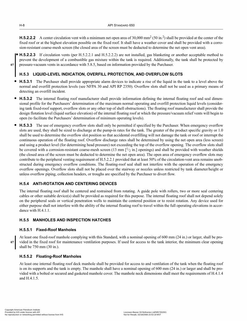
H-8 API STANDARD 650
•07
•
•
•
07
Copyright AmProvided by No reproduc
H.5.2.2.2 A center circulation vent with a minimum net open area of 30,000 mm2 (50 in.2) shall be provided at the center of thefixed roof or at the highest elevation possible on the fixed roof. It shall have a weather cover and shall be provided with a corro-sion-resistant coarse-mesh screen (the closed area of the screen must be deducted to determine the net open vent area).
H.5.2.2.3 If circulation vents (per H.5.2.2.1 and H.5.2.2.2) are not installed, gas blanketing or another acceptable method toprevent the development of a combustible gas mixture within the tank is required. Additionally, the tank shall be protected bypressure-vacuum vents in accordance with 5.8.5, based on information provided by the Purchaser.
H.5.3 LIQUID-LEVEL INDICATION, OVERFILL PROTECTION, AND OVERFLOW SLOTS
H.5.3.1 The Purchaser shall provide appropriate alarm devices to indicate a rise of the liquid in the tank to a level above thenormal and overfill protection levels (see NFPA 30 and API RP 2350). Overflow slots shall not be used as a primary means ofdetecting an overfill incident.
H.5.3.2 The internal floating roof manufacturer shall provide information defining the internal floating roof and seal dimen-sional profile for the Purchasers’ determination of the maximum normal operating and overfill protection liquid levels (consider-ing tank fixed-roof support, overflow slots or any other top of shell obstructions). The floating roof manufacturer shall provide thedesign flotation level (liquid surface elevation) of the internal floating roof at which the pressure/vacuum relief vents will begin toopen (to facilitate the Purchasers’ determination of minimum operating levels).
H.5.3.3 The use of emergency overflow slots shall only be permitted if specified by the Purchaser. When emergency overflowslots are used, they shall be sized to discharge at the pump-in rates for the tank. The greater of the product specific gravity or 1.0shall be used to determine the overflow slot position so that accidental overfilling will not damage the tank or roof or interrupt thecontinuous operation of the floating roof. Overflow discharge rates shall be determined by using the net open area (less screen)and using a product level (for determining head pressure) not exceeding the top of the overflow opening. The overflow slots shallbe covered with a corrosion-resistant coarse-mesh screen (13 mm [1/2 in.] openings) and shall be provided with weather shields(the closed area of the screen must be deducted to determine the net open area). The open area of emergency overflow slots maycontribute to the peripheral venting requirement of H.5.2.2.1 provided that at least 50% of the circulation-vent area remains unob-structed during emergency overflow conditions. The floating-roof seal shall not interfere with the operation of the emergencyoverflow openings. Overflow slots shall not be placed over the stairway or nozzles unless restricted by tank diameter/height orunless overflow piping, collection headers, or troughs are specified by the Purchaser to divert flow.
H.5.4 ANTI-ROTATION AND CENTERING DEVICES
The internal floating roof shall be centered and restrained from rotating. A guide pole with rollers, two or more seal centeringcables or other suitable device(s) shall be provided as required for this purpose. The internal floating roof shall not depend solelyon the peripheral seals or vertical penetration wells to maintain the centered position or to resist rotation. Any device used foreither purpose shall not interfere with the ability of the internal floating roof to travel within the full operating elevations in accor-dance with H.4.1.1.
H.5.5 MANHOLES AND INSPECTION HATCHES
H.5.5.1 Fixed-Roof Manholes
At least one fixed-roof manhole complying with this Standard, with a nominal opening of 600 mm (24 in.) or larger, shall be pro-vided in the fixed roof for maintenance ventilation purposes. If used for access to the tank interior, the minimum clear openingshall be 750 mm (30 in.).
H.5.5.2 Floating-Roof Manholes
At least one internal floating roof deck manhole shall be provided for access to and ventilation of the tank when the floating roofis on its supports and the tank is empty. The manhole shall have a nominal opening of 600 mm (24 in.) or larger and shall be pro-vided with a bolted or secured and gasketed manhole cover. The manhole neck dimensions shall meet the requirements of H.4.1.4and H.4.1.5.
--``,,,,,,`,,`,`,`,``,,````,,``-`-`,,`,,`,`,,`---
erican Petroleum Institute IHS under license with API Licensee=Bazan Oil Refineries Ltd/5957352001
Not for Resale, 02/18/2008 23:53:18 MSTtion or networking permitted without license from IHS

WELDED STEEL TANKS FOR OIL STORAGE H-9
•
•
•
07
•
•07
•
•
•07
•
Copyright AmericaProvided by IHS uNo reproduction o
H.5.5.3 Inspection Hatches
When specified by the Purchaser, inspection hatches shall be located on the fixed roof to permit visual inspection of the sealregion. The maximum spacing between inspection hatches shall be 23 m (75 ft), but there shall not be fewer than four equally-spaced hatches. Designs that combine inspection hatches with tank-shell circulation vents (located on the tank roof) areacceptable.
H.5.6 INLET DIFFUSER
Purchaser shall specify the need for an inlet diffuser sized to reduce the inlet velocity to less than 1 m (3 ft) per second during ini-tial fill per API RP 2003. Purchaser shall provide pumping rates and any blending, pigging and recirculation data along with theinlet diameter, for manufacturer’s determination of the diffuser design and size.
H.5.7 GAUGING AND SAMPLING DEVICES
When specified by the Purchaser, the fixed roof and the internal floating roof shall be provided with and/or accommodate gaugingand sampling devices. Sampling devices on the deck of the floating roof shall be installed beneath the fixed-roof hatch (as speci-fied for this purpose) and, unless designed as a gauge pole (extending up to the fixed roof), shall have a funneled (tapered) coverto facilitate use from the roof of the tank. All such devices on the floating roof shall be installed within the plumbness tolerance ofH.4.5. See C.3.14 for additional requirements applicable to gauge wells and poles.
H.5.8 CORROSION GAUGE
When specified by the Purchaser, a corrosion gauge for the internal floating roof shall be provided adjacent to the ladder to indi-cate the general corrosion rate.
H.5.9 FOAM DAMS
A foam dam, if specified on the Data Sheet, Line 32, shall be fabricated and installed in compliance with NFPA 11.
H.6 Fabrication, Erection, Welding, Inspection, and TestingH.6.1 The applicable fabrication, erection, welding, inspection, and testing requirements of this Standard shall be met. Uponthe start of internal floating roof installation, or concurrent with assembly within a tank under construction, the tank (interior shelland vertical components) shall be inspected by the floating roof erector, unless otherwise specified. The purpose of this inspectionshall be to confirm plumbness of all interior components, along with roundness and the condition of the shell (for the presence ofdamage, projections, or obstructions) to verify that the floating roof and seals will operate properly. Any defects, projections,obstructions or tank tolerance limits (exceeding those defined in 7.5 of this Standard), which would inhibit proper internal floatingroof and seal operation, that are identified by the internal floating roof erector shall be reported to the Purchaser.
H.6.2 Deck seams and other joints that are required to be or vapor-tight per H.4.1.3 shall be tested for leaks by the shop or fieldjoint assembler. Joint testing shall be performed by means of penetrating oil or another method consistent with those described inthis Standard for testing cone-roof and/or tank-bottom seams, or by any other method mutually agreed upon by the Purchaser andthe roof manufacturer.
H.6.3 The floating roof manufacturer shall supply all floating roof closures required for testing per H.4.1.3, H.4.1.7, H.4.3.1,and H.6.2. Rivets, self-tapping screws, and removable sections are not acceptable for test plugs.
H.6.4 Any flotation compartment that is completely shop-fabricated or assembled in such a manner as to permit leak testingat the fabricating shop shall be leak tested at the shop as well as retested in the field by the floating roof erector for all accessi-ble seams. In the field assembly yard or in the erected position, the erector shall spot leak test 10% of the flotation compart-ments, whether shop- or field-fabricated. The Purchaser may select the specific compartments to test and the test location,based on his visual inspections for indications of damage or potential leaks (see the Data Sheet, Line 34). Any leaking com-partments shall be repaired and re-tested by the roof manufacturer. If the testing finds any leaks in compartments tested, exceptfor those damaged by shipping, then 100% of the roof compartments shall be leak tested. Unless prohibited by safety concerns,leak testing shall be at an internal pressure of 20 kPa – 55 kPa (3 lbf/in.2 – 8 lbf/in.2) gauge using a soap solution or commer-cial leak detection solution.
Note: Special contract terms may be required to cover the costs of the field testing.
n Petroleum Institute nder license with API Licensee=Bazan Oil Refineries Ltd/5957352001
Not for Resale, 02/18/2008 23:53:18 MSTr networking permitted without license from IHS
--``,,,,,,`,,`,`,`,``,,````,,``-`-`,,`,,`,`,,`---

H-10 API STANDARD 650
•
07 •
Copyright AmProvided by No reproduc
--``,,,,,,`,,`,`,`,``,,````,,``-`-`,,`,,`,`,,`---
H.6.5 Upon assembly and prior to a flotation test, the erector shall inspect to verify that the peripheral seal produces an accept-able fit against the tank shell.
H.6.6 INITIAL FLOTATION
A flotation test and initial fill inspection shall be conducted by the Purchaser. This test may be performed or witnessed by theerector, as subject to agreement with the Purchaser. The party performing the flotation test shall make water connections and sup-ply all tank closures required for testing and remove all water connections and temporary closures (including gaskets, fasteners,test blanks, etc.) after completion of the test, unless otherwise specified by the Purchaser.
H.6.6.1 Internal floating roofs in accordance with types H.2.2a, b, c, d, and g. shall be given a flotation test on water. Internalfloating roofs in accordance with types H.2.2e and H.2.2f shall be given a flotation test on water or product at the option of thePurchaser. During this test, the roof and all accessible compartments shall be checked to confirm that they are free from leaks. Theappearance of a damp spot on the upper side of the part in contact with the liquid shall be considered evidence of leakage.
H.6.6.2 During initial fill the internal floating roof should be checked to confirm that it travels freely to its full height. Theperipheral seal shall be checked for proper operation throughout the entire travel of the internal floating roof. During the firstevent of lowering the level from full height, particular attention shall be given for tanks that contain a floating suction to insureproper operation.
H.6.6.3 Because of possible corrosive effects, consideration shall be given to the quality of water used and the duration of thetest. Potable water is recommended. For aluminum or stainless steel floating roofs, S.4.10 shall be followed.
H.6.6.4 The high flotation level shall be evaluated for clearance and the floating suction (if existing) shall be compensated forthe excess buoyancy that will be encountered during hydrostatic testing of the floating roof system.
erican Petroleum Institute IHS under license with API Licensee=Bazan Oil Refineries Ltd/5957352001
Not for Resale, 02/18/2008 23:53:18 MSTtion or networking permitted without license from IHS

•
•
07
Copyright AmericaProvided by IHS uNo reproduction o
APPENDIX I—UNDERTANK LEAK DETECTION AND SUBGRADE PROTECTION
I.1 Scope and BackgroundI.1.1 This appendix provides acceptable construction details for the detection of product leaks through the bottoms of above-ground storage tanks, and provides guidelines for tanks supported by grillage.
Note: API supports a general position of installation of a Release Prevention Barrier (RPB) under new tanks during initial construction. An RPBincludes steel bottoms, synthetic materials, clay liners, and all other barriers or combination of barriers placed in the bottom of or under anaboveground storage tank, which have the following functions: (a) preventing the escape of contaminated material, and (b) containing or chan-neling released material for leak detection.
I.1.2 Several acceptable construction details are provided for detection of leaks through the tank bottom and details for tankssupported by grillage (see Figures I-1 through I-11). Alternative details or methods may be used if agreed upon by the tank ownerand Manufacturer, provided the details or methods satisfy the requirements of I.2.
I.1.3 The tank owner shall determine whether the undertank area is to be constructed for leak detection. If leak detection isrequired, the owner shall specify the method or methods to be employed.
I.1.4 The bottoms of aboveground storage tanks may leak as a result of product side corrosion, soil side corrosion, or a combi-nation of both. The extent of product side corrosion can be detected using standard inspection techniques during an internalinspection, but determining the nature and extent of soil side corrosion is more difficult. Therefore, in certain services and tanklocations, it may be desirable to provide for undertank monitoring of leakage through the tank bottom plates.
I.1.5 For additional information on the use of internal coatings to prevent internal bottom corrosion, see API RP 652. Similarly,see API RP 651 for guidelines and requirements relating to preventing corrosion from the soil side of the bottom plate.
I.1.6 When the appropriate tank foundation design is being selected, it is important to consider the environmental and safetyregulatory implications of leakage of tank contents into the containment space below the tank bottom. Specifically, the contami-nation of permeable material such as sand used as a floor support may constitute the generation of a hazardous waste. The treat-ment or disposal costs of such contaminated material must be determined.
I.1.7 The requirements for secondary containment as it relates to diked areas and impoundments are not within the scope of thisappendix.
I.2 Performance RequirementsThe following general requirements shall be satisfied for all leak detection systems:
a. Leaks through the tank bottom shall be detectable by observation at the tank perimeter. If a leak is detected, it shall becollected.b. The use of electronic sensors for the detection of vapors and liquids is acceptable; however, the requirements of Item a aboveshall be satisfied. Any such sensor shall be fail-safe or have provision for calibration.
Flexible membrane liner
Tank bottom
Slope down
Gravel at drain
Tank shell
Bond liner to ringwallfor leak-tight connection
Concrete ringwall
Sand pad
Drain pipeSee API RP 651for evaluation ofcathodic protectionmethods
Figure I-1—Concrete Ringwall with Undertank Leak Detection at the Tank Perimeter (Typical Arrangement)
--``,,,,,,`,,`,`,`,``,,````,,``-`-`,,`,,`,`,,`---
I-1
n Petroleum Institute nder license with API Licensee=Bazan Oil Refineries Ltd/5957352001
Not for Resale, 02/18/2008 23:53:18 MSTr networking permitted without license from IHS

I-2 API STANDARD 650
•
Copyright AmProvided by No reproduc
--``,,,,,,`,,`,`,`,``,,````,,``-`-`,,`,,`,`,,`---
c. The materials of construction shall be chemically resistant to the range of products to be stored at the temperature rangeexpected in service. Other physical properties shall be specified by the tank owner.d. The permeability of the leak detection barrier shall not exceed 1 × 10⁻⁷ cm (4 × 10⁻⁵ mils) per second.e. The material in contact with the subgrade shall be suitable for below-grade service or be protected against degradation.f. The leak barrier shall be of one-piece construction, or the joints shall satisfy the leak tightness, permeability, and chemicalresistance requirements for the base leak-barrier material. The Manufacturer and a complete description of the leak barrier mate-rial shall be identified to the tank owner.g. The installation of sumps and pipes below the tank bottom is acceptable; however, the required leak detection and leak tight-ness shall be maintained. See Figures I-8 and I-9 for typical details.
I.3 Cathodic ProtectionCathodic protection systems may be installed in conjunction with undertank leak detection systems. See API RP 651 for guide-lines on the use of cathodic protection methods.
I.4 Double Steel Bottom ConstructionI.4.1 If a double steel bottom is used, the details of construction shall provide for the proper support of the primary bottomand shell for all operating conditions. The design shall be evaluated to verify that the primary bottom and shell are not over-stressed. The evaluation shall consider all anticipated operating conditions such as design metal temperature, maximum designtemperature, fill height, hydrostatic testing, seismic conditions, and tank settlement. The evaluation is not required if the pri-mary bottom is uniformly supported on both sides of the shell and is not structurally attached to the secondary bottom or pri-mary bottom support.
Figure I-2—Crushed Stone Ringwall with Undertank Leak Detectionat the Tank Perimeter (Typical Arrangement)
Flexiblemembrane liner
Sand cushionTank bottom
Slope
Sand or gravel backfillDrain pipe
Crushed stone ringwall
Asphalt on surface of gravel
Flexible membrane linerbetween two asphalt- impregnated fiberboards (19 mm [3/4 in.] thickness)
Tank shell
Gravel at drain
See API RP 651for evaluation of cathodicprotection methods
Flexiblemembraneliner
Slope
Tank bottom
Tank shell
Gravel at drainDrain pipe
Asphalt on surfaceof tank pad
Flexible membrane linerbetween two asphalt- impregnated fiberboards (19 mm [3/4 in.] thickness)
Sand cushion
See API RP 651for evaluation ofcathodic protectionmethods
Figure I-3—Earthen Foundation with Undertank Leak Detection at the Tank Perimeter (Typical Arrangement)
erican Petroleum Institute IHS under license with API Licensee=Bazan Oil Refineries Ltd/5957352001
Not for Resale, 02/18/2008 23:53:18 MSTtion or networking permitted without license from IHS

WELDED STEEL TANKS FOR OIL STORAGE I-3
Copyright AmericaProvided by IHS uNo reproduction o
I.4.2 For double steel bottom systems that use steel members (such as grating, structural shapes, or wire mesh) to separate thebottoms, ingress of water between the bottoms will result in local accelerated corrosion rates. If the perimeter of the bottoms is notsealed, corrosion protection of the tank bottoms shall be provided.
I.5 Material Requirements and Construction DetailsI.5.1 The minimum thickness of flexible-membrane leak barriers shall be 800 millimicrons (30 mils) for fiber-reinforced mem-branes and 1000 millimicrons (40 mils) for unreinforced membranes. If clay liners are used, they shall be thick enough to meetthe permeability requirements of I.2, Item d.
I.5.2 The leak barrier shall be protected as required to prevent damage during construction. If the foundation fill or tank padmaterial is likely to cause a puncture in the leak barrier, a layer of sand or fine gravel or a geotextile material shall be used as aprotective cushion.
I.5.3 For a flexible-membrane liner installed over a steel bottom, all nicks, burrs, and sharp edges shall be removed or a layer offine sand, gravel, or geotextile material shall be used to protect the liner.
I.5.4 The flexible leak barrier shall be covered by at least 100 mm (4 in.) of sand, except as otherwise shown in Figures I-1through I-10. This dimension may have to be increased if cathodic protection is to be provided in the space between the tank bot-tom and the leak barrier.
Figure I-4—Double Steel Bottom with Leak Detection at the Tank Perimeter (Typical Arrangement)
Secondary tank bottom
Tank shell
Primary tank bottom
Flexible membrane liner
Tight attachmentto shell
Optional - this seam may be sealedby caulking or welding (if welded,see I.4). Not sealing may accelerate bottom side corrosion.
Drain pipes not shown
Concrete ringwall shown(crushed stone alternative)
See API RP 651 for cathodic protection recommendations
Sand, pea gravel, or concrete with drainage grooves on top side
Shell support ring (continuous)
See API RP 651 for evaluation ofcathodic protection methods
Wire fabric
25 mm (1 in.) (min)
Tank shell
t
2t (25 mm [1 in.] min)
Alternative floor supports
NPS 1/2 pipecoupling at drain
Grating orstructural shapes
Optional - this seam may be sealedby caulking or welding (if welded,see I.4). Not sealing may accelerate bottom side corrosion.
Figure I-5—Double Steel Bottom with Leak Detection at the Tank Perimeter (Typical Arrangement)
n Petroleum Institute nder license with API Licensee=Bazan Oil Refineries Ltd/5957352001
Not for Resale, 02/18/2008 23:53:18 MSTr networking permitted without license from IHS
--``,,,,,,`,,`,`,`,``,,````,,``-`-`,,`,,`,`,,`---

I-4 API STANDARD 650
•
Copyright AmProvided by No reproduc
I.5.5 If drain pipes are used around the tank perimeter, they shall be at least NPS 1 in diameter and have a minimum wall thick-ness of Schedule 40. The pipes may be perforated in the undertank area to improve their leak detection function. The inner endsand perforations of the drain pipes shall be protected from clogging by the use of gravel, screening, geotextiles, or another methodapproved by the tank owner. The drain pipes shall exit through the foundation and shall be visible to indicate any leakage. If spec-ified by the owner, the undertank drains shall be fitted with a valve or piped to a leak detection well as shown in Figure I-10. Themaximum spacing of drain pipes shall be 15 m (50 ft), with a minimum of four drain pipes per tank; however, two drain pipesmay be used for tanks 6 m (20 ft) or less in diameter.
I.5.6 The need for pipe sleeves, expansion joints, or both in conjunction with drain pipes shall be evaluated.
I.5.7 The outlet of the drain pipes and collection sumps, if used, shall be protected from the ingress of water from externalsources.
I.5.8 Leak detection systems that use sumps in the liner below the tank bottom shall have a drain line that extends from thesump to the tank perimeter. Consideration shall be given to installation of supplemental perimeter drains.
I.6 Testing and InspectionI.6.1 The leak barrier, all leak-barrier penetrations, attachments of the leak barrier to the foundation ringwall, and other appurte-nances shall be visually inspected for proper construction in accordance with applicable specifications.
Figure I-6—Reinforced Concrete Slab with Leak Detection at the Perimeter (Typical Arrangement)
Compacted sand fill
Slope
Concrete slab
Piles (if required)
Drain pipe withoptional sleeve
Flexible liner bonded towall for leak tightness
Gravel or geotextilematerial at drain
Tank bottom
Tank shell
Flexible membrane liner or applied coating for leak tightness
See API RP 651for evaluation ofcathodic protectionmethods
Radial grooveson top of slabTank bottom
Tank shell
Piles (if required)
Reinforced concrete slab to be designed for leak tightness per ACI 350
Slope
Drain groovesat edge
Figure I-7—Reinforced Concrete Slab with Radial Grooves for Leak Detection (Typical Arrangement)
--``,,,,,,`,,`,`,`,``,,````,,``-`-`,,`,,`,`,,`---
erican Petroleum Institute IHS under license with API Licensee=Bazan Oil Refineries Ltd/5957352001
Not for Resale, 02/18/2008 23:53:18 MSTtion or networking permitted without license from IHS

WELDED STEEL TANKS FOR OIL STORAGE I-5
•
•
•
•
Copyright AmericaProvided by IHS uNo reproduction o
I.6.2 The shop and field seams of flexible-membrane liners shall pass a vacuum-box test. All leaks shall be repaired andretested. Alternative testing methods may be used with the tank owner’s approval.
I.6.3 Proof testing of samples of the flexible-membrane liner seam shall be performed to verify the seam strength and flexibilityand the adequacy of the bonding. The procedure (including testing methods) used to bond or weld the liner seams shall be submittedto the owner for review and shall specify all critical parameters, such as temperature, speed, surface preparation, and curing time,required to achieve liquid-tight seams. The required strength and flexibility of the liner seams shall be agreed upon by the tank ownerand Manufacturer. The seam samples shall be produced at the beginning of each shift for each operator and welding machine.
I.6.4 All liner penetrations, attachments of the liner to the foundation ringwall, and other appurtenances shall be demonstratedto be leak tight. This may be demonstrated by a mock-up test, prior experience, or other methods acceptable to the owner.
I.7 Tanks Supported by GrillageI.7.1 Tanks designed and constructed in accordance with API Std 650 that have a maximum nominal shell thickness of 13 mm(1/2 in.), including any customer specified corrosion allowance, and maximum design temperature not exceeding 93°C (200°F)may be supported by steel or concrete grillage. By agreement between the Purchaser and the Manufacturer, these rules may beapplied to tanks with shell thickness greater than 13 mm (1/2 in.). These rules apply to single steel butt-welded bottoms supportedby grillage members.
I.7.2 The thickness and design metal temperature of the bottom plate shall be in accordance with Figure 4-1.
I.7.3 The maximum spacing between adjacent or radial grillage members and the bottom plate thickness shall satisfy therequirements of I.7.3.1 and I.7.3.2.
Figure I-8—Typical Drawoff Sump
Floor sump
100 mm (4 in.) sand cushion
Tank bottom
Gravel at drain
Slope
Drain pipe with optional sleeve.Discharge to leak detectionwell or perimeter
Flexible membrane liner to follow contour of excavation
Flexible membrane liner bonded to sump (Alternative is to continue liner into the sump as a lining)
100 mm (4 in.) sand cushion
Gravel at drain
300 mm (12 in.) diameter (min) sump
Drain pipe with optional sleeve.Discharge to leak detectionwell or perimeter
Figure I-9—Center Sump for Downward-Sloped Bottom
--``,,,,,,`,,`,`,`,``,,````,,``-`-`,,`,,`,`,,`---
n Petroleum Institute nder license with API Licensee=Bazan Oil Refineries Ltd/5957352001
Not for Resale, 02/18/2008 23:53:18 MSTr networking permitted without license from IHS

I-6 API STANDARD 650
•
Copyright AmProvided by No reproduc
I.7.3.1 The maximum spacing between adjacent or radial grillage members shall not exceed:
(I.7.3.1-1)
I.7.3.2 The required minimum thickness of the bottom plate supported on grillage shall be determined by the followingequation:
(I.7.3.2-1)
where
b = maximum allowable spacing (center-to-center) between adjacent or radial grillage members, in mm (in.),Fy = specified minimum yield strength of bottom plate material, in MPa (psi),
tg = nominal thickness (including any corrosion allowance) of the bottom plate supported on grillage, in mm (in.),
CA = corrosion allowance to be added to the bottom plate, in mm (in.). The Purchaser shall specify the corrosion allowance,
p = uniform pressure (including the weight of the bottom plate) acting on the bottom resulting from the greater of the weight of the product plus any internal pressure, or the weight of the hydrostatic test water, in MPa (psi).
Figure I-10—Typical Leak Detection Wells
Drain pipe to well.Pipe may be abovegrade or below grade (with pipe sleeve)
Ringwall foundation shown. Detail is typical for all types of foundations
See note
Detection well100 mm (4 in.) diameter (min)with top hatch
Note: Top of well shall be above maximum high water level within dike.
See note
Removable weather cover
Detection well (concrete pitadjacent to concrete ringwall)
Drain pipe
b1.5Fy tg CA–( )2
p-------------------------------------
0.5
=
tgb2 p( )1.5Fy-------------
0.5
CA+=
erican Petroleum Institute IHS under license with API Licensee=Bazan Oil Refineries Ltd/5957352001
Not for Resale, 02/18/2008 23:53:18 MSTtion or networking permitted without license from IHS
--``,,,,,,`,,`,`,`,``,,````,,``-`-`,,`,,`,`,,`---

WELDED STEEL TANKS FOR OIL STORAGE I-7
•
Copyright AmericaProvided by IHS uNo reproduction o
I.7.3.3 The maximum calculated deflection of the bottom plate at mid-span shall not exceed (tg – CA) / 2:
(I.7.3.3-1)
where
d = maximum calculated deflection of the bottom plate at mid-span, in mm (in.),
Es = modulus of elasticity of the bottom plate material, in MPa (psi).
I.7.4 The bottom plates shall be jointed together by butt-welds having complete penetration and complete fusion. Joints shall bevisually inspected prior to welding to ensure the weld gap and fit-up will allow complete penetration. Each weld pass shall bevisually inspected. The alignment and spacing of grillage members shall be such that the joints between bottom plates are locatedapproximately above the center of the grillage members to the greatest extent practical. Grillage members shall be arranged tominimize the length of unsupported tank shell spanning between grillage members.
I.7.5 Grillage members shall be symmetrical about their vertical centerline. Steel grillage members shall be designed to preventweb crippling and web buckling as specified in Chapter K of the AISC Manual of Steel Construction, Allowable Stress Design.Concrete grillage members may also be used.
I.7.6 The Purchaser shall specify the corrosion allowance to be added to steel grillage members. If a corrosion allowance isrequired, the manner of application (added to webs only, added to webs and flanges, added to one surface, added to all surfaces,and so forth) shall also be specified.
I.7.7 For tanks designed to withstand wind or seismic loads, provisions shall be made to prevent sliding, distortion, and over-turning of the grillage members. Lateral bracing between the top and bottom flanges of adjacent steel grillage members may berequired to prevent distortion and overturning. The lateral bracing and connections shall be designed to transfer the specified lat-eral loads. If friction forces between the grillage members and the foundation are not adequate to transfer the specified later load,the grillage members shall be anchored to the foundation.
I.7.8 The tank shall be anchored to resist uplift forces (in excess of the corroded dead load) due to pressure and wind or seismicoverturning. Anchors shall be located near the intersection of the tank shell and a grillage member, or near an additional stiffeningmember.
I.7.9 The tank shell shall be designed to prevent local buckling at the grillage members and consideration shall be given to shelldistortion when the spacing of the grillage members is determined.
I.7.10 The bottom plate and grillage members directly beneath roof support columns and other items supported by the bot-tom shall be designed for the loads imposed. Additional support members are to be furnished if required to adequately supportthe bottom.
I.7.11 If flush-type cleanouts or flush-type shell connections are furnished, additional support members shall be provided toadequately support the bottom-reinforcing and bottom-transition plates. As a minimum, the additional support members shallconsist of a circumferential member (minimum length and location according to Method A of Figure 5-12) and radial supportmembers. The radial support members shall extend from the circumferential member to the inner edge of the bottom reinforcing(for flush-type cleanouts) or bottom-transition plate (for flush-type shell connections). The circumferential spacing of the radialsupport members shall not exceed 300 mm (12 in.).
I.7.12 For tanks located in a corrosive environment, and where atmospheric corrosion due to wet/dry cycles may occur, consid-eration shall be given to protecting the soil side of the bottom plates, grillage members, and in particular, the contact surfacebetween the bottom plates and grillage members by utilizing protective coatings or by adding a corrosion allowance to thesemembers.
I.8 Typical InstallationsAlthough it is not the intent of this appendix to provide detailed designs for the construction of undertank leak detection systemsand tanks supported by grillage, Figures I-1 through I-11 illustrate the general use and application of the recommendations pre-sented in this appendix.
d 0.0284pb4
Es tg CA–( )3----------------------------- tg CA–( ) / 2≤=
--``,,,,,,`,,`,`,`,``,,````,,``-`-`,,`,,`,`,,`---
n Petroleum Institute nder license with API Licensee=Bazan Oil Refineries Ltd/5957352001
Not for Resale, 02/18/2008 23:53:18 MSTr networking permitted without license from IHS

I-8 API STANDARD 650
Copyright AmProvided by No reproduc
Figure I-11—Tanks Supported by Grillage Members (General Arrangement)
SECTION A-A
A A
AA
Locate anchors neargrillage members
b b b
bb
bb
b
Anchorage (if required)
Top offoundation
Butt-welded joint
Grillage membersButt-welded joint
Lateral bracing (if required)
t g
erican Petroleum Institute IHS under license with API Licensee=Bazan Oil Refineries Ltd/5957352001
Not for Resale, 02/18/2008 23:53:18 MSTtion or networking permitted without license from IHS
--``,,,,,,`,,`,`,`,``,,````,,``-`-`,,`,,`,`,,`---

•
Copyright AmericaProvided by IHS uNo reproduction o
APPENDIX J—SHOP-ASSEMBLED STORAGE TANKS
J.1 ScopeJ.1.1 This appendix provides requirements for the design and fabrication of vertical storage tanks in sizes that permit completeshop assembly and delivery to the installation site in one piece. Storage tanks designed according to this appendix shall not exceed6 m (20 ft) in diameter.
J.1.2 The application of this appendix to the design and fabrication of shop-assembled storage tanks shall be mutually agreedupon by the Purchaser and the Manufacturer.
J.2 MaterialsThe material requirements of Section 4 of this Standard are applicable.
J.3 DesignJ.3.1 JOINTS
J.3.1.1 Joints shall be designed as specified in 5.1; however, lap-welded joints in bottoms are not permissible. In addition, themodifications given in J.3.1.2 through J.3.1.5 are applicable.
J.3.1.2 All shell joints shall be butt-welded so that full penetration is produced without the use of back-up bars.
J.3.1.3 Shell plates shall be sized to limit the number of plates to the smallest practical number consistent with sound economicpractice. Each course should preferably be constructed of one plate.
J.3.1.4 Top angles are not required for flanged-roof tanks.
J.3.1.5 Joints in bottom plates shall be butt-welded. The welding shall produce complete penetration of the parent metal.
J.3.2 BOTTOMSJ.3.2.1 All bottom plates shall have a minimum nominal thickness of 6 mm (1/4 in.) (49.8 kg/m2 [10.2 lbf/ft2], see 2.2.1.2 and3.4.1).
J.3.2.2 Bottoms shall be constructed of a minimum number of pieces; wherever feasible they shall be constructed of one piece.
J.3.2.3 Bottoms may be flat or flat flanged. A flat-bottom shall project at least 25 mm (1 in.) beyond the outside diameter of theweld attaching the bottom to the shell plate. A flat-flanged bottom shall have an inside corner radius that is not less than threetimes the bottom thickness and a straight flange that is a minimum of 19 mm (3/4 in.).
J.3.2.4 For flat bottoms, the attachment between the bottom edges of the lowest course shell plate and the bottom plate shall bea continuous fillet weld laid on each side of the shell plate. Each fillet weld shall be sized in accordance with 5.1.5.7. A flat-flanged bottom shall be attached to the shell by full-penetration butt-welds.
J.3.3 SHELLS
Shell plates shall be designed in accordance with the formula given in A.4.1, but the nominal thickness of shell plates shall not beless than the following:
a. For tanks with a diameter less than or equal to 3.2 m (10.5 ft) – 5 mm (3/16 in.).b. For tanks with a diameter greater than 3.2 m (10.5 ft) – 6 mm (1/4 in.).
J.3.4 WIND GIRDERS FOR OPEN-TOP TANKS
Open-top tanks shall be provided with wind girders as specified in 5.9.
J.3.5 ROOFS
J.3.5.1 General
Roofs for tanks constructed in accordance with this appendix shall be of the self-supporting type and shall conform to eitherJ.3.5.2 or J.3.5.3.
--``,,,,,,`,,`,`,`,``,,````,,``-`-`,,`,,`,`,,`---
J-1
n Petroleum Institute nder license with API Licensee=Bazan Oil Refineries Ltd/5957352001
Not for Resale, 02/18/2008 23:53:18 MSTr networking permitted without license from IHS
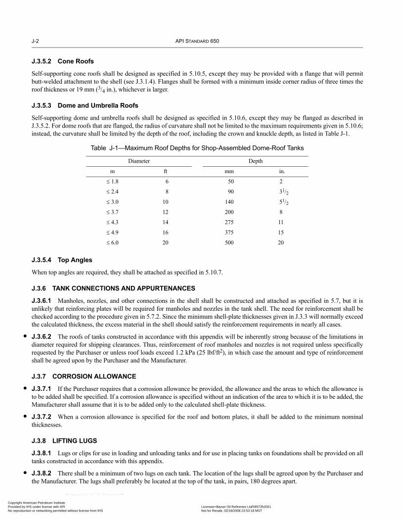
J-2 API STANDARD 650
•
•
•
•
Copyright AmProvided by No reproduc
J.3.5.2 Cone Roofs
Self-supporting cone roofs shall be designed as specified in 5.10.5, except they may be provided with a flange that will permitbutt-welded attachment to the shell (see J.3.1.4). Flanges shall be formed with a minimum inside corner radius of three times theroof thickness or 19 mm (3/4 in.), whichever is larger.
J.3.5.3 Dome and Umbrella Roofs
Self-supporting dome and umbrella roofs shall be designed as specified in 5.10.6, except they may be flanged as described inJ.3.5.2. For dome roofs that are flanged, the radius of curvature shall not be limited to the maximum requirements given in 5.10.6;instead, the curvature shall be limited by the depth of the roof, including the crown and knuckle depth, as listed in Table J-1.
J.3.5.4 Top Angles
When top angles are required, they shall be attached as specified in 5.10.7.
J.3.6 TANK CONNECTIONS AND APPURTENANCES
J.3.6.1 Manholes, nozzles, and other connections in the shell shall be constructed and attached as specified in 5.7, but it isunlikely that reinforcing plates will be required for manholes and nozzles in the tank shell. The need for reinforcement shall bechecked according to the procedure given in 5.7.2. Since the minimum shell-plate thicknesses given in J.3.3 will normally exceedthe calculated thickness, the excess material in the shell should satisfy the reinforcement requirements in nearly all cases.
J.3.6.2 The roofs of tanks constructed in accordance with this appendix will be inherently strong because of the limitations indiameter required for shipping clearances. Thus, reinforcement of roof manholes and nozzles is not required unless specificallyrequested by the Purchaser or unless roof loads exceed 1.2 kPa (25 lbf/ft2), in which case the amount and type of reinforcementshall be agreed upon by the Purchaser and the Manufacturer.
J.3.7 CORROSION ALLOWANCE
J.3.7.1 If the Purchaser requires that a corrosion allowance be provided, the allowance and the areas to which the allowance isto be added shall be specified. If a corrosion allowance is specified without an indication of the area to which it is to be added, theManufacturer shall assume that it is to be added only to the calculated shell-plate thickness.
J.3.7.2 When a corrosion allowance is specified for the roof and bottom plates, it shall be added to the minimum nominalthicknesses.
J.3.8 LIFTING LUGS
J.3.8.1 Lugs or clips for use in loading and unloading tanks and for use in placing tanks on foundations shall be provided on alltanks constructed in accordance with this appendix.
J.3.8.2 There shall be a minimum of two lugs on each tank. The location of the lugs shall be agreed upon by the Purchaser andthe Manufacturer. The lugs shall preferably be located at the top of the tank, in pairs, 180 degrees apart.
Table J-1—Maximum Roof Depths for Shop-Assembled Dome-Roof Tanks
Diameter Depth
m ft mm in.
≤ 1.8 6 50 2
≤ 2.4 8 90 31/2≤ 3.0 10 140 51/2≤ 3.7 12 200 8
≤ 4.3 14 275 11
≤ 4.9 16 375 15
≤ 6.0 20 500 20
erican Petroleum Institute IHS under license with API Licensee=Bazan Oil Refineries Ltd/5957352001
Not for Resale, 02/18/2008 23:53:18 MSTtion or networking permitted without license from IHS
--``,,,,,,`,,`,`,`,``,,````,,``-`-`,,`,,`,`,,`---

WELDED STEEL TANKS FOR OIL STORAGE J-3
07
•
Copyright AmericaProvided by IHS uNo reproduction o
--``,,,,,,`,,`,`,`,``,,````,,``-`-`,,`,,`,`,,`---
J.3.8.3 Lugs and their attachment welds shall be designed to carry their share of the applied load (twice the empty weight of thetank) distributed in a reasonable manner and based on a safety factor of 4.
J.3.8.4 Lugs capable of carrying the load described in J.3.8.3 shall be designed and attached in a manner that will not damagethe tank.
J.3.9 ANCHORING
Because of the proportions of shop-assembled storage tanks, overturning as a result of wind loading must be considered. If neces-sary, adequate provisions for anchoring shall be provided.
J.4 Fabrication and ConstructionJ.4.1 GENERAL
J.4.1.1 Fabrication and construction shall be in accordance with the applicable provisions of Sections 6 and 7 of this Standard.Erection shall be interpreted as assembly, and it shall be understood that the entire vessel is constructed in the shop and not at thefield site.
J.4.1.2 Sections 7.2.2 and 7.2.5 of this Standard are not applicable to the bottoms and roofs of shop-assembled tanks.
J.4.2 TESTING, REPAIRS, AND INSPECTION
J.4.2.1 General
For testing of, repairs to, and inspection of shop-assembled tanks, the requirements of J.4.2.2 through J.4.2.4 replace those of5.3.2 through 5.3.6.
J.4.2.2 Testing
Unless otherwise specified by the Purchaser, as an alternative to the requirements of 7.3.2 through 7.3.7, a tank may be shoptested for leaks by the following method:
a. The tank bottom shall be braced by securely attaching an external stiffening member as required to prevent permanent defor-mation during the test.b. All openings shall be closed with plugs or covers as needed. Bolts and gaskets of the size and type required for final installa-tion shall be used during the test.c. An internal air pressure of 14 kPa – 21 kPa (2 lbf/in.2 – 3 lbf/in.2) gauge shall be applied to the tank. For tanks with a diameterof 3.7 m (12 ft) or less, a maximum pressure of 35 kPa (5 lbf/in.2) gauge shall be used.d. Soap film, linseed oil, or another material suitable for the detection of leaks shall be applied to all shell, bottom, roof, andattachment welds, and the tank shall be carefully examined for leaks.e. After the air pressure is released, the external stiffening member shall be removed, and any weld scars shall be repaired.
J.4.2.3 Repairs
All weld defects found by the leak test or by radiographic examination shall be repaired as specified in Section 8.
J.4.2.4 Inspection
The Purchaser’s inspector shall have free entry to the Manufacturer’s shop at all times. The Manufacturer shall afford the Pur-chaser’s inspector reasonable facilities to assure the inspector that the work is being performed in accordance with the require-ments of this Standard. All material and workmanship shall be subject to the replacement requirements of 6.2.3.
J.5 Inspection of Shell JointsThe methods of inspecting shell joints described in Section 8 apply to shop-assembled tanks, but spot radiography may be omittedwhen a joint efficiency of 0.70 is used (see A.3.4).
n Petroleum Institute nder license with API Licensee=Bazan Oil Refineries Ltd/5957352001
Not for Resale, 02/18/2008 23:53:18 MSTr networking permitted without license from IHS

J-4 API STANDARD 650
Copyright AmProvided by No reproduc
J.6 Welding Procedure and Welder QualificationsThe requirements for qualification of welding procedures and welders given in Section 9 apply to shop-assembled tanks.
J.7 MarkingShop-assembled tanks shall be marked in accordance with Section 10, except that 10.1.4 and 10.2 are not applicable. The name-plate (see Figure 10-1) shall indicate that the tank has been designed in accordance with this appendix.
erican Petroleum Institute IHS under license with API Licensee=Bazan Oil Refineries Ltd/5957352001
Not for Resale, 02/18/2008 23:53:18 MSTtion or networking permitted without license from IHS
--``,,,,,,`,,`,`,`,``,,````,,``-`-`,,`,,`,`,,`---

07
Copyright AmericaProvided by IHS uNo reproduction o
--``,,,,,,`,,`,`,`,``,,````,,``-`-`,,`,,`,`,,`---
APPENDIX K—SAMPLE APPLICATION OF THE VARIABLE-DESIGN-POINT METHOD TO DETERMINE SHELL-PLATE THICKNESS
K.1 Data[ ] Design condition [X] Test conditionSpecific gravity of liquid, G:. . . . . . . . . . . . . . . . . . . . . . . . . . . . . . . . . . . . . . . . . . . . 1.0Corrosion allowance:. . . . . . . . . . . . . . . . . . . . . . . . . . . . . . . . . . . . . . . . . . . . . . . . . . 0.0 mm (0.0 in.)Tank diameter, D: . . . . . . . . . . . . . . . . . . . . . . . . . . . . . . . . . . . . . . . . . . . . . . . . . . .85.0 m (280 ft)Design Liquid Level (also total height of tank for the
examples in this appendix), H: . . . . . . . . . . . . . . . . . . . . . . . . . . . . . . . . . . . . 19.2 m (64 ft)Number of courses: . . . . . . . . . . . . . . . . . . . . . . . . . . . . . . . . . . . . . . . . . . . . . . . . . . . 8.0Allowable stress for design, Sd: . . . . . . . . . . . . . . . . . . . . . . . . . . . . . . . . . . . . . . . . —Allowable stress for testing, St: 208 MPa (30,000 lbf/in.2)Height of bottom course, h1: . . . . . . . . . . . . . . . . . . . . . . . . . . . . . . . . . . . . . . . . . .2,400 mm (96 in.)Nominal tank radius, r: . . . . . . . . . . . . . . . . . . . . . . . . . . . . . . . . . . . . . . . . . . . . .42,500 mm (1,680 in.)
(See 5.6.4 for definition of nomenclature.)
K.2 CalculationsK.2.1 FIRST COURSE (t1)
For the test condition, t1 is equal to t1t but not greater than tpt.
In SI units:
tpt =
t1t =
=
= [1.06 – (0.3081)(0.3038)][38.45]= [1.06 – 0.0936][38.45]= [0.9664][38.45]= 37.15 mm = t1
In US Customary units:
tpt =
t1t =
=
= [1.06 – (2.026)(0.0462)][1.553]= [1.06 – 0.0936][1.553]= [0.9664][1.553]= 1.501 in. = t1
4.9D H 0.3–( )St
---------------------------------- 4.9( ) 85( ) 19.2 0.3–( )208
---------------------------------------------------- 37.85= =
1.06 0.0696DH
---------------------– HSt----
4.9HD( )St
---------------------
1.06 0.0696 85( )19.2
---------------------------– 19.2208----------
4.9 19.2( ) 85( )208
----------------------------------
2.6D H 1–( )St
------------------------------ 2.6 280( ) 64 1–( )30,000
----------------------------------------- 1.529= =
1.06 0.463D( )H
----------------------– HSt---- 2.6HD( )
St---------------------
1.06 0.463 280( )64
---------------------------– 6430,000----------------
2.6 64( ) 280( )30,000
--------------------------------
K-1
n Petroleum Institute nder license with API Licensee=Bazan Oil Refineries Ltd/5957352001
Not for Resale, 02/18/2008 23:53:18 MSTr networking permitted without license from IHS

K-2 API STANDARD 650
Copyright AmProvided by No reproduc
--``,,,,,,`,,`,`,`,``,,````,,``-`-`,,`,,`,`,,`---
K.2.2 SECOND COURSE (t2)
In SI units:
If ≤1.375, t2 = t1; if ≥ 2.625, t2 = t2a
If 1.375 < < 2.625
t2 =
=
= 31.28 + (5.87)[2.1 – 1.528]
= 31.28 + (5.87)[0.572]
= 31.28 + 3.36
= 34.64 mm
In US Customary units:
If ≤1.375, t2 = t1; if ≥ 2.625, t2 = t2a
If 1.375 < < 2.625
t2 =
=
= 1.263 + (0.238)[2.1 – 1.529]
= 1.263 + (0.238)[0.571]
= 1.263 + 0.136
= 1.399 in.
h1
rt1( )0.5--------------- 240042,500( ) 37.2( )[ ]0.5---------------------------------------------- 1.909= =
h1
rt1( )0.5---------------h1
rt1( )0.5---------------
h1
rt1( )0.5---------------
t2a t1 t2a–( ) 2.1h1
1.25 rt1( )0.5--------------------------–
+
31.28 5.87( ) 2.1 24001.25 42,500( ) 37.16( )[ ]0.5------------------------------------------------------------–
+
h1
rt1( )0.5--------------- 961680( ) 1.501( )[ ]0.5-------------------------------------------- 96
50.216---------------- 1.912= = =
h1
rt1( )0.5---------------h1
rt1( )0.5---------------
h1
rt1( )0.5---------------
t2a t1 t2a–( ) 2.1h1
1.25 rt1( )0.5--------------------------–
+
1.263 0.238( ) 2.1 961.25 1680( ) 1.501( )[ ]0.5-------------------------------------------------------–
+
erican Petroleum Institute IHS under license with API Licensee=Bazan Oil Refineries Ltd/5957352001
Not for Resale, 02/18/2008 23:53:18 MSTtion or networking permitted without license from IHS

WELDED STEEL TANKS FOR OIL STORAGE K-3
Copyright AmericaProvided by IHS uNo reproduction o
--``,,,,,,`,,`,`,`,``,,````,,``-`-`,,`,,`,`,,`---
K.2.3 UPPER COURSES
K.2.3.1 Course 2Note: H = 16.8 m (56 ft).
K.2.3.1.1 First Trial
In SI units:
ttx =
= 33.04 mm = tutL = 37.15 mm
K =
K0.5 = 1.060
C =
(rtu)0.5 = [(42,500)(33.04)]0.5 = 1185.0x1 = 0.61(rtu)0.5 + 320CH
= 0.61(1185) + 320(0.060)(16.8) = 1045.4x2 = 1000CH = 1000(0.060)(16.8) = 1008x3 = 1.22(rtu)0.5 = 1.22(1185) = 1445.7x = min(x1, x2, x3) = 1008
x/1000 = 1.008
ttx =
In US Customary units:
ttx =
= 1.335 in. = tutL = 1.501 in.
K =
K0.5 = 1.060
C =
(rtu)0.5 = [(1680)(1.335)]0.5 = 47.358x1 = 0.61(rtu)0.5 + 3.84CH
= 0.61(47.358) + 3.84(0.060)(56) = 28.89 + 12.90 = 41.79x2 = 12CH = 12(0.060)(56) = 40.32x3 = 1.22(rtu)0.5 = 1.22(47.358) = 57.78x = min(x1, x2, x3) = 40.32
x/12 = 3.36
ttx =
With this value of ttx, start the second trial.
4.9D H 0.3–( )St
---------------------------------- 4.9 85( ) 16.8 0.3–( )208
-----------------------------------------------=
tL
tu--- 37.15
33.04------------- 1.124= =
K0.5 K 1–( )1 K1.5+
-------------------------- 1.06( ) 0.124( )1 1.192+
--------------------------------- 0.060= =
4.9D H x–( )St
----------------------------- 4.9 85( ) 16.8 1.008–( )208
----------------------------------------------------- 31.62 mm= =
2.6D H 1–( )St
------------------------------ 2.6 280( ) 55( )30,000
--------------------------------=
tL
tu--- 1.501
1.335------------- 1.124= =
K0.5 K 1–( )1 K1.5+
-------------------------- 1.06( ) 0.124( )1 1.191+
--------------------------------- 0.060= =
2.6D H x 12⁄–( )St
--------------------------------------- 2.6 280( ) 56 3.36–( )30,000
------------------------------------------------ 1.277 in.= =
n Petroleum Institute nder license with API Licensee=Bazan Oil Refineries Ltd/5957352001
Not for Resale, 02/18/2008 23:53:18 MSTr networking permitted without license from IHS

K-4 API STANDARD 650
Copyright AmProvided by No reproduc
K.2.3.1.2 Second Trial
In SI units:
tu = ttx from first trial = 31.62 mm
tL = 37.15 mm
K =
K0.5 = 1.084
C =
(rtu)0.5 = [(42,500)(31.62)]0.5 = 1159.2
x1 = 0.61(rtu)0.5 + 320CH
= 0.61(1159.2) + 320(0.0834)(16.8) = 1155.5x2 = 1000CH = 1000(0.0834)(16.8) = 1401.1
x3 = 1.22(rtu)0.5 = 1.22(1159.2) = 1414.2
x = min(x1, x2, x3) = 1155.5
x/1000 = 1.155
ttx =
In US Customary units:
tu = ttx from first trial = 1.277 in.
tL = 1.501 in.
K =
K0.5 = 1.084
C =
(rtu)0.5 = [(1680)(1.277)]0.5 = 46.32
x1 = 0.61(rtu)0.5 + 3.84CH
= 0.61(46.32) + 3.84(0.0834)(56) = 28.25 + 17.93 = 46.19x2 = 12CH = 12(0.0834)(56) = 56.04
x3 = 1.22(rtu)0.5 = 1.22(46.32) = 56.51
x = min(x1, x2, x3) = 46.19
x/12 = 3.80
ttx =
With this value of ttx, start the third trial.
tL
tu--- 37.15
31.62------------- 1.175= =
K0.5 K 1–( )1 K1.5+
-------------------------- 1.084( ) 0.175( )1 1.1751.5+
------------------------------------ 0.0834= =
4.9D H x 1000⁄–( )St
--------------------------------------------- 4.9 85( ) 16.8 1.155–( )208
----------------------------------------------------- 31.33 mm= =
tL
tu--- 1.501
1.277------------- 1.175= =
K0.5 K 1–( )1 K1.5+
-------------------------- 1.084( ) 0.175( )1 1.274+
------------------------------------ 0.0834= =
2.6D H x 12⁄–( )St
--------------------------------------- 2.6 280( ) 56 3.80–( )30,000
------------------------------------------------ 1.267 in.= =
--``,,,,,,`,,`,`,`,``,,````,,``-`-`,,`,,`,`,,`---
erican Petroleum Institute IHS under license with API Licensee=Bazan Oil Refineries Ltd/5957352001
Not for Resale, 02/18/2008 23:53:18 MSTtion or networking permitted without license from IHS

WELDED STEEL TANKS FOR OIL STORAGE K-5
Copyright AmericaProvided by IHS uNo reproduction o
K.2.3.1.3 Third Trial
In SI units:
tu = ttx from second trial = 31.33 mm
tL = 37.15 mm
K =
K0.5 = 1.089
C =
(rtu)0.5 = [(42,500)(31.33)]0.5 = 1153.9
x1 = 0.61(rtu)0.5 + 320CH
= 0.61(1153.9) + 320(0.088)(16.8) = 1177.0x2 = 1000CH = 1000(0.088)(16.8) = 1478.4
x3 = 1.22(rtu)0.5 = 1.22(1153.9) = 1407.8
x = min(x1, x2, x3) = 1177
x/1000 = 1.177
ttx =
In US Customary units:
tu = ttx from first trial = 1.267 in.
tL = 1.501 in.
K =
K0.5 = 1.089
C =
(rtu)0.5 = [(1680)(1.266)]0.5 = 46.12
x1 = 0.61(rtu)0.5 + 3.84CH
= 0.61(46.12) + 3.84(0.088)(56) = 28.13 + 18.92 = 47.05x2 = 12CH = 59.14
x3 = 1.22(rtu)0.5 = 1.22(46.12) = 56.27
x = min(x1, x2, x3) = 47.05
x/12 = 3.92
ttx =
Use this value to calculate t2.
tL
tu--- 37.15
31.33------------- 1.186= =
K0.5 K 1–( )1 K1.5+
-------------------------- 1.089( ) 0.186( )1 1.1861.5+
------------------------------------ 0.088= =
4.9D H x 1000⁄–( )St
--------------------------------------------- 4.9 85( ) 16.8 1.177–( )208
----------------------------------------------------- 31.28 mm t2a== =
tL
tu--- 1.501
1.267------------- 1.185= =
K0.5 K 1–( )1 K1.5+
-------------------------- 1.089( ) 0.185( )1 1.290+
------------------------------------ 0.088= =
2.6D H x 12⁄–( )St
--------------------------------------- 2.6 280( ) 56 3.92–( )30,000
------------------------------------------------ 1.263 in. t2a== =
n Petroleum Institute nder license with API Licensee=Bazan Oil Refineries Ltd/5957352001
Not for Resale, 02/18/2008 23:53:18 MSTr networking permitted without license from IHS
--``,,,,,,`,,`,`,`,``,,````,,``-`-`,,`,,`,`,,`---

K-6 API STANDARD 650
Copyright AmProvided by No reproduc
--``,,,,,,`,,`,`,`,``,,````,,``-`-`,,`,,`,`,,`---
K.2.3.2 Course 3
Note: H = 14.4 m (48 ft).
K.2.3.2.1 First Trial
In SI units:
ttx =
= 28.23 mm = tutL = 34.64 mm
K =
K0.5 = 1.108
C =
(rtu)0.5 = [(42,500)(28.23)]0.5 = 1095x1 = 0.61(rtu)0.5 + 320CH
= 0.61(1095) + 320(0.107)(14.4) = 1161x2 = 1000CH = 1000(0.107)(14.4) = 1541x3 = 1.22(rtu)0.5 = 1.22(1095) = 1336x = min(x1, x2, x3) = 1161
x/1000 = 1.161
ttx =
In US Customary units:
ttx =
= 1.141 in. = tutL = 1.399 in.
K =
K0.5 = 1.107
C =
(rtu)0.5 = [(1680)(1.141)]0.5 = 43.78x1 = 0.61(rtu)0.5 + 3.84CH
= 0.61(43.78) + 3.84(0.106)(48) = 26.71 + 19.54 = 46.25x2 = 12CH = 12(0.106)(48) = 61.06x3 = 1.22(rtu)0.5 = 1.22(43.78) = 53.41x = min(x1, x2, x3) = 46.25
x/12 = 3.85
ttx =
With this value of ttx, start the second trial.
4.9D H 0.3–( )St
---------------------------------- 4.9 85( ) 14.4 0.3–( )208
-----------------------------------------------=
tL
tu--- 34.64
28.23------------- 1.227= =
K0.5 K 1–( )1 K0.5+
-------------------------- 1.108( ) 0.227( )1 1.2271.5+
------------------------------------ 0.107= =
4.9D H x 1000⁄–( )St
--------------------------------------------- 4.9 85( ) 14.4 1.161–( )208
----------------------------------------------------- 26.51 mm= =
2.6D H 1–( )St
------------------------------ 2.6 280( ) 47( )30,000
--------------------------------=
tL
tu--- 1.399
1.141------------- 1.226= =
K0.5 K 1–( )1 K1.5+
-------------------------- 1.107( ) 0.266( )1 1.357+
------------------------------------ 0.106= =
2.6D H x 12⁄–( )St
--------------------------------------- 2.6 280( ) 48 3.85–( )30,000
------------------------------------------------ 1.071 in.= =
erican Petroleum Institute IHS under license with API Licensee=Bazan Oil Refineries Ltd/5957352001
Not for Resale, 02/18/2008 23:53:18 MSTtion or networking permitted without license from IHS
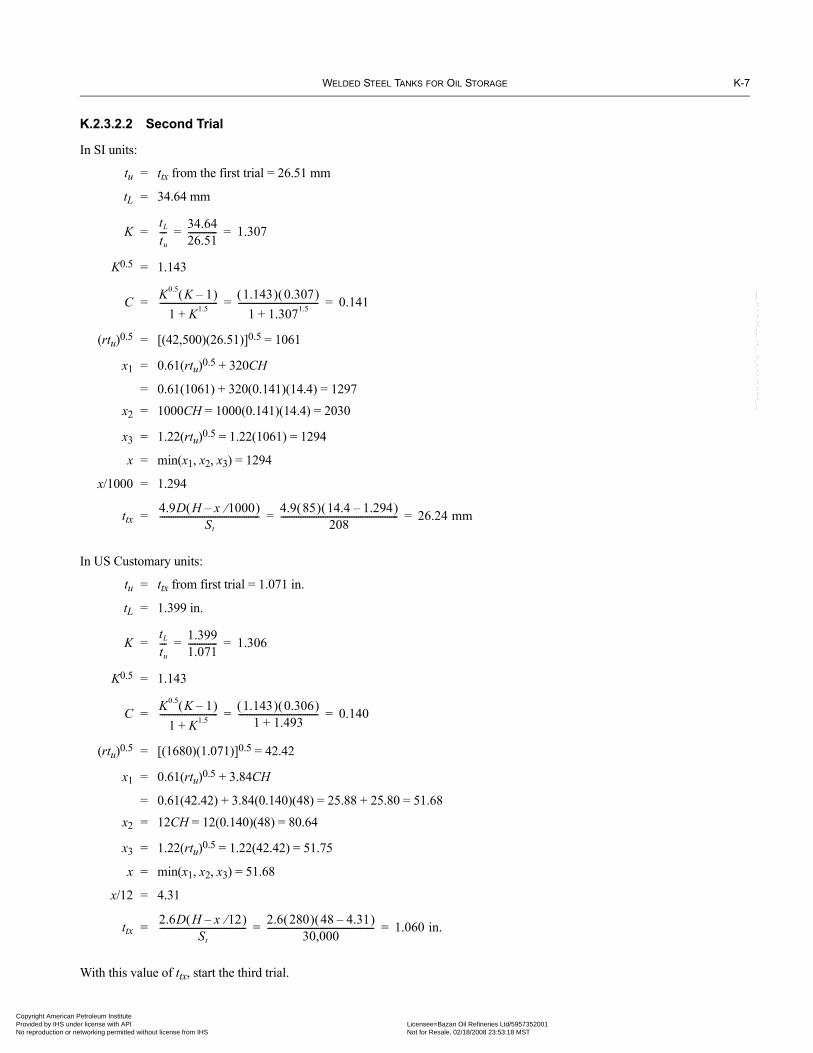
WELDED STEEL TANKS FOR OIL STORAGE K-7
Copyright AmericaProvided by IHS uNo reproduction o
K.2.3.2.2 Second Trial
In SI units:
tu = ttx from the first trial = 26.51 mm
tL = 34.64 mm
K =
K0.5 = 1.143
C =
(rtu)0.5 = [(42,500)(26.51)]0.5 = 1061
x1 = 0.61(rtu)0.5 + 320CH
= 0.61(1061) + 320(0.141)(14.4) = 1297
x2 = 1000CH = 1000(0.141)(14.4) = 2030
x3 = 1.22(rtu)0.5 = 1.22(1061) = 1294
x = min(x1, x2, x3) = 1294
x/1000 = 1.294
ttx =
In US Customary units:
tu = ttx from first trial = 1.071 in.
tL = 1.399 in.
K =
K0.5 = 1.143
C =
(rtu)0.5 = [(1680)(1.071)]0.5 = 42.42
x1 = 0.61(rtu)0.5 + 3.84CH
= 0.61(42.42) + 3.84(0.140)(48) = 25.88 + 25.80 = 51.68
x2 = 12CH = 12(0.140)(48) = 80.64
x3 = 1.22(rtu)0.5 = 1.22(42.42) = 51.75
x = min(x1, x2, x3) = 51.68
x/12 = 4.31
ttx =
With this value of ttx, start the third trial.
tL
tu--- 34.64
26.51------------- 1.307= =
K0.5 K 1–( )1 K1.5+
-------------------------- 1.143( ) 0.307( )1 1.3071.5+
------------------------------------ 0.141= =
4.9D H x 1000⁄–( )St
--------------------------------------------- 4.9 85( ) 14.4 1.294–( )208
----------------------------------------------------- 26.24 mm= =
tL
tu--- 1.399
1.071------------- 1.306= =
K0.5 K 1–( )1 K1.5+
-------------------------- 1.143( ) 0.306( )1 1.493+
------------------------------------ 0.140= =
2.6D H x 12⁄–( )St
--------------------------------------- 2.6 280( ) 48 4.31–( )30,000
------------------------------------------------ 1.060 in.= =
--``,,,,,,`,,`,`,`,``,,````,,``-`-`,,`,,`,`,,`---
n Petroleum Institute nder license with API Licensee=Bazan Oil Refineries Ltd/5957352001
Not for Resale, 02/18/2008 23:53:18 MSTr networking permitted without license from IHS

K-8 API STANDARD 650
Copyright AmProvided by No reproduc
K.2.3.2.3 Third Trial
In SI units:
tu = ttx from the second trial = 26.24 mm
tL = 34.64 mm
K =
K0.5 = 1.149
C =
(rtu)0.5 = [(42,500)(26.24)]0.5 = 1056
x1 = 0.61(rtu)0.5 + 320CH
= 0.61(1056) + 320(0.146)(14.4) = 1317
x2 = 1000CH = 1000(0.146)(14.4) = 2102
x3 = 1.22(rtu)0.5 = 1.22(1056) = 1288
x = min(x1, x2, x3) = 1288
x/1000 = 1.288
ttx =
In US Customary units:
tu = ttx from second trial = 1.060 in.
tL = 1.399 in.
K =
K0.5 = 1.149
C =
(rtu)0.5 = [(1680)(1.06)]0.5 = 42.20
x1 = 0.61(rtu)0.5 + 3.84CH
= 0.61(42.40) + 3.84(0.146)(48) = 25.74 + 26.91 = 52.65
x2 = 12CH = 12(0.146)(48) = 84.10
x3 = 1.22(rtu)0.5 = 1.22(42.20) = 51.48
x = min(x1, x2, x3) = 51.48
x/12 = 4.29
ttx =
(Sample calculated shell-plate thicknesses for various tank sizes and allowable stresses are given in Tables K-1 through K-3.)
tL
tu--- 34.64
26.24------------- 1.320= =
K0.5 K 1–( )1 K1.5+
-------------------------- 1.149( ) 0.320( )1 1.3201.5+
------------------------------------ 0.146= =
4.9D H x 1000⁄–( )St
--------------------------------------------- 4.9 85( ) 14.4 1.288–( )208
----------------------------------------------------- 26.26 mm for Course 3= =
tL
tu--- 1.399
1.060------------- 1.320= =
K0.5 K 1–( )1 K1.5+
-------------------------- 1.149( ) 0.320( )1 1.517+
------------------------------------ 0.146= =
2.6D H x 12⁄–( )St
--------------------------------------- 2.6 280( ) 48 4.29–( )30,000
------------------------------------------------ 1.061 in. for Course 3= =
--``,,,,,,`,,`,`,`,``,,````,,``-`-`,,`,,`,`,,`---
erican Petroleum Institute IHS under license with API Licensee=Bazan Oil Refineries Ltd/5957352001
Not for Resale, 02/18/2008 23:53:18 MSTtion or networking permitted without license from IHS

WE
LDE
D STE
EL TA
NK
S FOR O
IL STO
RA
GE
K-9
Table K-1—Shell-Plate Thicknesses Based on the Variable-Design-Point Method (See 5.6.4)
ion
T NominalTank Volume
m3 (bbl)8
— 33,900 (224,000)— 39,800 (271,000)— 53,000 (322,500)— 60,300 (378,500)— 68,100 (439,000)— 76,300 (504,000)— 94,200 (573,400)— 103,900 (647,300)— 114,000 (725,700)— 124,600 (808,600)
1 — 34,200 (217,700)— 40,700 (268,800)— 47,800 (325,200)— 63,600 (387,000)— 72,400 (454,200)— 81,700 (526,800)— 91,600 (596,700)
1 — 33,000 (200,700)— 39,900 (254,000)— 47,500 (313,600)— 55,700 (379,400)— 74,200 (451,500)— 78,200 (478,300)
1 .00 (0.313) 37,700 (229,300).00 (0.313) 45,600 (290,300).00 (0.313) 54,300 (358,400).00 (0.375) 58,900 (402,600)
Copyright A
merican P
etroleum Institute
Provided by IH
S under license w
ith AP
I Licensee=
Bazan O
il Refineries Ltd/5957352001
Not for R
esale, 02/18/2008 23:53:18 MS
TN
o reproduction or networking perm
itted without license from
IHS
Using 2400-mm (96-in.) Courses and an Allowable Stress of 159 MPa (23,000 lbf/in.2) for the Test Condit
ank Des.Liq. Lvl.
m (ft)
TankDiameter
m (ft)
Weightof Shell
Mg (tons)
Shell Plate Thickness for Course, mm (in.)
1 2 3 4 5 6 7
12 (40) 60 (200) 233 (272) 21.40 (0.871) 16.18 (0.659) 11.96 (0.487) 8.00 (0.317) 8.00 (0.313) — —65 (220) 282 (333) 22.99 (0.949) 17.42 (0.720) 12.90 (0.533) 10.00 (0.375) 10.00 (0.375) — —75 (240) 363 (389) 26.09 (1.025) 20.95 (0.807) 14.58 (0.574) 10.00 (0.375) 10.00 (0.375) — —80 (260) 408 (453) 27.59 (1.099) 22.97 (0.907) 15.39 (0.613) 10.02 (0.398) 10.00 (0.375) — —85 (280) 457 (522) 29.06 (1.171) 24.95 (1.004) 16.21 (0.653) 10.59 (0.427) 10.00 (0.375) — —90 (300) 510 (594) 30.51 (1.241) 26.88 (1.098) 17.01 (0.692) 11.16 (0.454) 10.00 (0.375) — —
100 (320) 621 (671) 33.31 (1.310) 30.59 (1.189) 18.57 (0.730) 12.28 (0.482) 10.00 (0.375) — —105 (340) 680 (751) 34.66 (1.377) 32.40 (1.277) 19.32 (0.768) 12.84 (0.509) 10.00 (0.375) — —110 (360) 741 (835) 35.99 (1.433) 34.21 (1.362) 20.06 (0.804) 13.39 (0.536) 10.00 (0.375) — —115 (380) 804 (923) 37.29 (1.506) 35.94 (1.448) 20.78 (0.840) 13.93 (0.562) 10.00 (0.375) — —
4.4 (48) 55 (180) 276 (312) 23.90 (0.956) 18.85 (0.755) 14.99 (0.600) 11.06 (0.443) 8.00 (0.313) 8.00 (0.313) —60 (200) 322 (376) 25.90 (1.055) 20.43 (0.832) 16.29 (0.664) 11.96 (0.487) 8.00 (0.317) 8.00 (0.313) —65 (220) 388 (463) 27.85 (1.150) 22.54 (0.943) 17.49 (0.721) 12.89 (0.533) 10.00 (0.375) 10.00 (0.375) —75 (240) 505 (543) 31.65 (1.243) 27.47 (1.063) 19.76 (0.776) 14.78 (0.579) 10.00 (0.375) 10.00 (0.375) —80 (260) 569 (633) 33.50 (1.334) 29.85 (1.181) 20.92 (0.833) 15.71 (0.625) 10.00 (0.397) 10.00 (0.375) —85 (280) 638 (729) 35.32 (1.423) 32.17 (1.295) 22.05 (0.889) 16.63 (0.669) 10.53 (0.424) 10.00 (0.375) —90 (298) 711 (821) 37.11 (1.502) 34.44 (1.394) 23.17 (0.938) 17.54 (0.710) 11.08 (0.448) 10.00 (0.375) —
6.8 (56) 50 (160) 306 (333) 25.42 (0.995) 20.83 (0.817) 17.30 (0.678) 13.69 (0.537) 10.15 (0.398) 8.00 (0.313) 8.00 (0.313)55 (180) 364 (412) 27.97 (1.119) 22.77 (0.912) 18.98 (0.760) 14.96 (0.599) 11.06 (0.443) 8.00 (0.313) 8.00 (0.313)60 (200) 428 (502) 30.42 (1.239) 25.25 (1.033) 20.54 (0.836) 16.27 (0.663) 11.96 (0.487) 8.00 (0.317) 8.00 (0.313)65 (220) 514 (615) 32.73 (1.351) 28.17 (1.175) 22.02 (0.908) 17.59 (0.727) 12.89 (0.532) 10.00 (0.375) 10.00 (0.375)75 (240) 671 (723) 37.24 (1.462) 33.81 (1.313) 25.01 (0.982) 20.17 (0.790) 14.72 (0.577) 10.00 (0.375) 10.00 (0.375)77 (247) 705 (764) 38.12 (1.500) 34.91 (1.361) 25.60 (1.007) 20.69 (0.812) 15.09 (0.592) 10.00 (0.379) 10.00 (0.375)
9.2 (64) 50 (160) 390 (423) 29.12 (1.139) 24.42 (0.957) 20.95 (0.820) 17.28 (0.677) 13.69 (0.537) 10.15 (0.398) 8.00 (0.313) 855 (180) 466 (527) 32.03 (1.282) 27.03 (1.078) 22.92 (0.918) 18.95 (0.758) 14.98 (0.599) 11.06 (0.443) 8.00 (0.313) 860 (200) 551 (646) 34.95 (1.423) 30.39 (1.242) 24.75 (1.007) 20.63 (0.841) 16.27 (0.662) 11.96 (0.487) 8.00 (0.317) 862.5 (212) 610 (735) 36.29 (1.502) 32.04 (1.338) 25.66 (1.061) 21.47 (0.890) 16.91 (0.700) 12.41 (0.514) 10.00 (0.375) 10
--``,,,,,,`,,`,`,`,``,,````,,``-`-`,,`,,`,`,,`---

K-10
AP
I STA
ND
AR
D 650
Table K-2—Shell-Plate Thicknesses Based on the Variable-Design-Point Method (See 5.6.4)Using 2400-mm (96-in.) Courses and an Allowable Stress of 208 MPa (30,000 lbf/in.2) for the Test Condition
NominalTank Volume
m3 (bbl)853,000 (322,500)60,300 (378,500)68,100 (439,000)76,300 (504,000)94,200 (573,400)
103,900 (647,300)114,000 (725,700)124,600 (800,600)135,700 (896,000)
47,800 (325,200)63,600 (387,000)72,400 (454,200)81,700 (526,800)91,600 (604,800)
113,100 (688,100)124,700 (776,800)136,800 (870,900)149,600 (970,300)162,900 (1,075,200)
47,500 (313,600)55,700 (379,400)74,200 (451,500)84,400 (529,900)95,300 (614,600)
106,900 (705,600)131,900 (802,800)145,500 (906,300)159,700 (1,016,000)174,500 (1,132,000)190,000 (1,204,700)
(0.313) 54,300 (358,400) (0.375) 63,700 (433,600) (0.375) 84,800 (516,000) (0.375) 96,500 (605,600) (0.375) 109,000 (702,400) (0.375) 122,100 (806,400) (0.375) 150,800 (917,500) (0.375) 153,800 (987,600)
Copyright A
merican P
etroleumP
rovided by IHS
under license with A
PI
Licensee=B
azan Oil R
efineries Ltd/5957352001 N
ot for Resale, 02/18/2008 23:53:18 M
ST
No reproduction or netw
orking permitted w
ithout license from IH
S
Tank Des.Liq. Lvl.
m (ft)
TankDiameter
m (ft)
Weightof Shell
Mg (tons)
Shell Plate Thickness for Course, mm (in.)
1 2 3 4 5 6 712 (40) 75 (240) 298 (320) 20.26 (0.798) 15.36 (0.603) 11.38 (0.447) 10.00 (0.375) 10.00 (0.375) — — —
80 (260) 332 (365) 21.45 (0.856) 16.48 (0.651) 12.06 (0.482) 10.00 (0.375) 10.00 (0.375) — — —85 (280) 369 (417) 22.63 (0.914) 18.07 (0.729) 12.65 (0.511) 10.00 (0.375) 10.00 (0.375) — — —90 (300) 409 (472) 23.78 (0.971) 19.63 (0.806) 13.27 (0.541) 10.00 (0.375) 10.00 (0.375) — — —
100 (320) 493 (530) 26.03 (1.026) 22.64 (0.880) 14.51 (0.572) 10.00 (0.375) 10.00 (0.375) — — —105 (340) 537 (594) 27.12 (1.080) 24.10 (0.952) 15.12 (0.602) 10.00 (0.395) 10.00 (0.375) — — —110 (360) 585 (661) 28.20 (1.133) 25.52 (1.022) 15.72 (0.632) 10.37 (0.416) 10.00 (0.375) — — —115 (380) 636 (731) 29.25 (1.185) 26.92 (1.090) 16.31 (0.660) 10.79 (0.437) 10.00 (0.375) — — —120 (400) 688 (803) 30.29 (1.235) 28.30 (1.156) 16.88 (0.689) 11.22 (0.458) 10.00 (0.375) — — —
14.4 (48) 65 (220) 316 (374) 21.55 (0.892) 16.99 (0.704) 13.52 (0.561) 10.00 (0.412) 10.00 (0.375) 10.00 (0.375) — —75 (240) 406 (436) 24.54 (0.966) 19.96 (0.773) 15.41 (0.608) 11.37 (0.446) 10.00 (0.375) 10.00 (0.375) — —80 (260) 456 (505) 26.01 (1.038) 21.86 (0.866) 16.27 (0.650) 12.09 (0.482) 10.00 (0.375) 10.00 (0.375) — —85 (280) 509 (579) 27.45 (1.109) 23.73 (0.958) 17.14 (0.692) 12.81 (0.517) 10.00 (0.375) 10.00 (0.375) — —90 (300) 565 (656) 28.87 (1.178) 25.55 (1.047) 18.02 (0.736) 13.52 (0.552) 10.00 (0.375) 10.00 (0.375) — —
100 (320) 684 (739) 31.64 (1.247) 29.10 (1.135) 19.76 (0.778) 14.92 (0.587) 10.00 (0.375) 10.00 (0.375) — —105 (340) 747 (827) 33.00 (1.314) 30.81 (1.220) 20.61 (0.820) 15.62 (0.621) 10.00 (0.392) 10.00 (0.375) — —110 (360) 814 (921) 34.33 (1.379) 32.49 (1.302) 21.44 (0.862) 16.31 (0.655) 10.28 (0.412) 10.00 (0.375) — —115 (380) 885 (1019) 35.65 (1.444) 34.18 (1.383) 22.26 (0.902) 17.01 (0.688) 10.68 (0.433) 10.00 (0.375) — —120 (400) 958 (1121) 36.94 (1.507) 35.83 (1.462) 23.08 (0.942) 17.73 (0.721) 11.08 (0.452) 10.00 (0.375) — —
16.8 (56) 60 (200) 341 (400) 23.32 (0.953) 19.05 (0.778) 15.85 (0.648) 12.51 (0.511) 9.27 (0.378) 8.00 (0.313) 8.00 (0.313) —65 (220) 410 (490) 25.27 (1.048) 20.53 (0.858) 17.13 (0.709) 13.50 (0.560) 10.00 (0.412) 10.00 (0.375) 10.00 (0.375) —75 (240) 533 (575) 28.84 (1.135) 24.92 (0.968) 19.40 (0.764) 15.51 (0.609) 11.36 (0.446) 10.00 (0.375) 10.00 (0.375) —80 (260) 601 (668) 30.58 (1.220) 27.09 (1.075) 20.53 (0.819) 16.50 (0.658) 12.07 (0.481) 10.00 (0.375) 10.00 (0.375) —85 (280) 672 (766) 32.29 (1.305) 29.23 (1.180) 21.68 (0.876) 17.48 (0.706) 12.76 (0.515) 10.00 (0.375) 10.00 (0.375) —90 (300) 747 (871) 33.98 (1.387) 31.33 (1.283) 22.82 (0.932) 18.46 (0.754) 13.46 (0.549) 10.00 (0.375) 10.00 (0.375) —
100 (320) 907 (981) 37.29 (1.469) 35.41 (1.383) 25.05 (0.987) 20.42 (0.801) 14.82 (0.583) 10.00 (0.375) 10.00 (0.375) —105 (340) 992 (1100) 38.91 (1.549) 37.39 (1.481) 26.14 (1.041) 21.46 (0.849) 15.48 (0.616) 10.00 (0.393) 10.00 (0.375) —110 (360) 1083 (1225) 40.51 (1.627) 39.36 (1.577) 27.23 (1.094) 22.64 (0.895) 16.11 (0.649) 10.30 (0.413) 10.00 (0.375) —115 (380) 1179 (1358) 42.08 (1.705) 41.28 (1.671) 28.33 (1.148) 23.79 (0.951) 16.74 (0.679) 10.72 (0.434) 10.00 (0.375) —120 (392) 1278 (1441) 43.63 (1.750) 43.14 (1.726) 29.44 (1.180) 24.94 (0.986) 17.36 (0.698) 11.14 (0.446) 10.00 (0.375) —
19.2 (64) 60 (200) 433 (508) 26.71 (1.092) 22.34 (0.913) 19.19 (0.784) 15.83 (0.647) 12.52 (0.511) 9.27 (0.378) 8.00 (0.313) 8.0065 (220) 520 (623) 28.94 (1.201) 24.70 (1.034) 20.63 (0.853) 17.11 (0.710) 13.51 (0.560) 10.00 (0.412) 10.00 (0.375) 10.0075 (240) 679 (734) 33.16 (1.304) 29.77 (1.159) 23.42 (0.922) 19.67 (0.772) 15.47 (0.608) 11.36 (0.447) 10.00 (0.375) 10.0080 (260) 766 (853) 35.17 (1.403) 32.22 (1.280) 24.85 (0.992) 20.93 (0.834) 16.45 (0.655) 12.06 (0.481) 10.00 (0.375) 10.0085 (280) 858 (981) 37.15 (1.501) 34.64 (1.399) 26.25 (1.061) 22.18 (0.896) 17.41 (0.703) 12.77 (0.516) 10.00 (0.375) 10.0090 (300) 955 (1116) 39.12 (1.597) 37.01 (1.515) 27.65 (1.129) 23.44 (0.957) 18.36 (0.749) 13.46 (0.550) 10.00 (0.375) 10.00
100 (320) 1163 (1259) 42.96 (1.692) 41.63 (1.629) 30.38 (1.196) 26.27 (1.017) 20.19 (0.796) 14.85 (0.584) 10.00 (0.375) 10.00101 (332) 1185 (1350) 43.34 (1.748) 42.08 (1.696) 30.65 (1.236) 26.56 (1.059) 20.37 (0.822) 14.98 (0.604) 10.00 (0.384) 10.00
07
Institute
--``,,,,,,`,,`,`,`,``,,````,,``-`-`,,`,,`,`,,`---

WE
LDE
D STE
EL TA
NK
S FOR O
IL STO
RA
GE
K-11
Table K-3—Shell-Plate Thicknesses Based on the Variable-Design-Point Method (See 5.6.4)2 n
NominalTank Volume
m3 (bbl)
47,800 (325,200)63,600 (387,000)72,400 (454,200)81,700 (526,800)91,600 (604,800)
113,100 (688,100)124,700 (776,800)136,800 (870,900)149,600 (970,300)162,900 (1,075,200)
47,500 (313,600)55,700 (379,400)74,200 (451,500)84,400 (529,900)95,300 (614,600)
106,900 (705,600)131,900 (802,800)145,500 (906,300)159,700 (1,016,000)174,500 (1,132,000)190,000 (1,254,400)
(0.313) 54,300 (358,400) (0.375) 63,700 (433,600) (0.375) 84,800 (516,000) (0.375) 96,500 (605,600) (0.375) 109,000 (702,400) (0.375) 122,100 (806,400) (0.375) 150,800 (917,500) (0.375) 166,300 (1,035,700) (0.375) 182,500 (1,161,200) (0.375) 199,400 (1,293,800) (0.375) 206,400 (1,321,200)
Copyright A
merican P
etroleum Institute
Provided by IH
S under license w
ith AP
I Licensee=
Bazan O
il Refineries Ltd/5957352001
Not for R
esale, 02/18/2008 23:53:18 MS
TN
o reproduction or networking perm
itted without license from
IHS
Using 2400-mm (96-in.) Courses and an Allowable Stress of 236 MPa (34,300 lbf/in. ) for the Test Conditio
Tank Des.Liq. Lvl.
m (ft)
Tank Diameter
m (ft)
Weightof Shell
Mg (tons)
Shell Plate Thickness for Course, mm (in.)
1 2 3 4 5 6 7 8
14.4 (48) 65 (220) 293 (341) 19.03 (0.784) 15.04 (0.619) 11.95 (0.492) 10.00 (0.375) 10.00 (0.375) 10.00 (0.375) — —75 (240) 368 (394) 21.76 (0.850) 17.19 (0.670) 13.70 (0.534) 10.05 (0.393) 10.00 (0.375) 10.00 (0.375) — —80 (260) 413 (453) 23.07 (0.914) 18.78 (0.736) 14.48 (0.574) 10.69 (0.423) 10.00 (0.375) 10.00 (0.375) — —85 (280) 460 (519) 24.36 (0.977) 20.45 (0.818) 15.24 (0.611) 11.33 (0.454) 10.00 (0.375) 10.00 (0.375) — —90 (300) 510 (588) 25.63 (1.039) 22.10 (0.898) 16.00 (0.649) 11.96 (0.485) 10.00 (0.375) 10.00 (0.375) — —
100 (320) 617 (662) 28.12 (1.100) 25.30 (0.977) 17.56 (0.687) 13.21 (0.515) 10.00 (0.375) 10.00 (0.375) — —105 (340) 674 (738) 29.34 (1.160) 26.85 (1.053) 18.32 (0.724) 13.82 (0.545) 10.00 (0.375) 10.00 (0.375) — —110 (360) 733 (819) 30.54 (1.218) 28.37 (1.127) 19.07 (0.761) 14.44 (0.575) 10.00 (0.375) 10.00 (0.375) — —115 (380) 794 (904) 31.73 (1.276) 29.87 (1.200) 19.81 (0.797) 15.05 (0.605) 10.00 (0.381) 10.00 (0.375) — —120 (400) 856 (994) 32.89 (1.333) 31.34 (1.271) 20.54 (0.832) 15.66 (0.634) 10.00 (0.399) 10.00 (0.375) — —
16.8 (56) 60 (200) 308 (358) 20.56 (0.834) 16.86 (0.684) 14.00 (0.568) 11.08 (0.449) 8.21 (0.333) 8.00 (0.313) 8.00 (0.313) —65 (220) 376 (441) 22.27 (0.917) 18.17 (0.747) 15.13 (0.623) 11.93 (0.491) 10.00 (0.375) 10.00 (0.375) 10.00 (0.375) —75 (240) 480 (514) 25.56 (0.998) 21.48 (0.825) 17.24 (0.674) 13.70 (0.534) 10.05 (0.393) 10.00 (0.375) 10.00 (0.375) —80 (260) 541 (596) 27.11 (1.074) 23.43 (0.921) 18.23 (0.723) 14.58 (0.577) 10.67 (0.422) 10.00 (0.375) 10.00 (0.375) —85 (280) 604 (684) 28.64 (1.149) 25.35 (1.015) 19.23 (0.771) 15.45 (0.620) 11.29 (0.453) 10.00 (0.375) 10.00 (0.375) —90 (300) 671 (777) 30.15 (1.222) 27.24 (1.107) 20.25 (0.821) 16.32 (0.662) 11.91 (0.483) 10.00 (0.375) 10.00 (0.375) —
100 (320) 815 (875) 33.12 (1.295) 30.92 (1.197) 22.24 (0.869) 18.04 (0.703) 13.12 (0.512) 10.00 (0.375) 10.00 (0.375) —105 (340) 891 (978) 34.57 (1.366) 32.70 (1.284) 23.22 (0.918) 18.90 (0.745) 13.72 (0.542) 10.00 (0.375) 10.00 (0.375) —110 (360) 970 (1086) 36.01 (1.436) 34.46 (1.370) 24.19 (0.965) 19.77 (0.786) 14.31 (0.571) 10.00 (0.375) 10.00 (0.375) —115 (380) 1053 (1200) 37.42 (1.505) 36.19 (1.454) 25.15 (1.012) 20.80 (0.827) 14.87 (0.600) 10.00 (0.382) 10.00 (0.375) —120 (400) 1139 (1322) 38.82 (1.573) 37.92 (1.536) 26.11 (1.058) 21.83 (0.873) 15.43 (0.627) 10.00 (0.400) 10.00 (0.375) —
19.2 (64) 60 (200) 389 (453) 23.54 (0.955) 19.76 (0.801) 16.94 (0.687) 13.98 (0.567) 11.08 (0.449) 8.21 (0.333) 8.00 (0.313) 8.0065 (220) 471 (556) 25.51 (1.051) 21.32 (0.884) 18.31 (0.752) 15.10 (0.622) 11.94 (0.491) 10.00 (0.375) 10.00 (0.375) 10.0075 (240) 609 (653) 29.37 (1.146) 25.79 (0.994) 20.78 (0.812) 17.37 (0.677) 13.67 (0.533) 10.05 (0.393) 10.00 (0.375) 10.0080 (260) 687 (759) 31.17 (1.235) 27.99 (1.102) 22.02 (0.872) 18.49 (0.731) 14.53 (0.575) 10.68 (0.423) 10.00 (0.375) 10.0085 (280) 769 (872) 32.94 (1.321) 30.16 (1.208) 23.27 (0.933) 19.60 (0.786) 15.39 (0.617) 11.30 (0.453) 10.00 (0.375) 10.0090 (300) 855 (992) 34.69 (1.406) 32.29 (1.311) 24.51 (0.994) 20.70 (0.839) 16.24 (0.658) 11.92 (0.483) 10.00 (0.375) 10.00
100 (320) 1041 (1119) 38.13 (1.490) 36.45 (1.413) 26.96 (1.053) 22.99 (0.893) 17.90 (0.699) 13.15 (0.513) 10.00 (0.375) 10.00105 (340) 1140 (1252) 39.82 (1.573) 38.47 (1.512) 28.16 (1.112) 24.27 (0.946) 18.70 (0.740) 13.76 (0.543) 10.00 (0.375) 10.00110 (360) 1243 (1394) 41.49 (1.655) 40.47 (1.610) 29.34 (1.170) 25.57 (1.007) 19.49 (0.779) 14.36 (0.572) 10.00 (0.375) 10.00115 (380) 1351 (1543) 43.14 (1.735) 42.45 (1.705) 30.55 (1.228) 26.85 (1.071) 20.27 (0.817) 14.97 (0.601) 10.00 (0.382) 10.00117 (384) 1395 (1574) 43.80a (1.751a) 43.22 (1.724) 31.03 (1.240) 27.36 (1.083) 20.59 (0.824) 15.21 (0.607) 10.00 (0.385) 10.00
aExceeds maximum allowed material thickness.--``,,,,,,`,,`,`,`,``,,````,,``-`-`,,`,,`,`,,`---

Copyright AmProvided by No reproduc
erican Petroleum Institute IHS under license with API Licensee=Bazan Oil Refineries Ltd/5957352001
Not for Resale, 02/18/2008 23:53:18 MSTtion or networking permitted without license from IHS
--``,,,,,,`,,`,`,`,``,,````,,``-`-`,,`,,`,`,,`---

•
••
• 07
•
•
Copyright AmericaProvided by IHS uNo reproduction o
--``,,,,,,`,,`,`,`,``,,````,,``-`-`,,`,,`,`,,`---
APPENDIX L—API STD 650 STORAGE TANK DATA SHEET
L.1 IntroductionL.1.1 PURPOSE
This appendix provides guidance to Purchasers (owners, engineering contractors, and other designated agents) and Manufacturers(fabricators and erectors) for the preparation and completion of the Atmospheric Storage Tank Data Sheet (hereafter referred to asthe Data Sheet). The Data Sheet shall be prepared in conjunction with this Standard such that comprehensive proposals (bids)may be made and subsequent contracts may be placed for the fabrication and erection of tanks.
L.1.2 SCOPE
This appendix explains information to be placed on the Data Sheet primarily by Purchasers for use by Manufacturers. However,some of the instructions apply to either the Purchaser or the Manufacturer, depending on which party assumes certain responsibilities.
L.2 Use of This AppendixL.2.1 DATA SHEET PURPOSE
The Data Sheet (attached to this appendix) shall be part of a complete tank specification. The Data Sheet provides space for defin-ing specific technical information such as geometry, design loads, materials, and appurtenances, as well as an outline sketch of thetank. The Data Sheet may be used as part of the Owner’s permanent record describing the tank. Because some information on theData Sheet may be determined by the Manufacturer, the Data Sheet may also be used to facilitate gathering of the completedesign requirements. The floating roof section of the Data Sheet may be omitted if no floating roof is required for the tank.
L.2.2 PURCHASER’S RESPONSIBILITY
The preparer(s) of the Data Sheet shall have tank design experience and shall ensure that the requirements are both accurate andcomplete. The Purchaser is primarily responsible for initiating and completing the Data Sheet.
L.2.3 MANUFACTURER’S RESPONSIBILITY
The Manufacturer shall complete the Data Sheet as required to describe the proposal and shall provide the relevant informationrequired on all lines marked with an asterisk (*) that have not been provided by the Purchaser. The Data Sheet shall be submittedat various times during the project as described in W.1.2(2).
L.2.4 TEXT LEGIBILITY
All text placed on the Data Sheet shall be of size and quality to be readable and reproducible. Use additional sheets or extend theform electronically for more space or necessary additions.
L.3 Specific InstructionsL.3.1 LINE-BY-LINE INSTRUCTIONS
Each place for data entry (numbered lines, boxes, table cells, etc.) on the Data Sheet shall be completed. In no case should a linebe left blank. Marking “NA” (not applicable), “Later,” “TBD” (to be determined), or other such terminology can be used. The“Later” and “TBD” notations shall be edited to reflect subsequent decisions and as-built configurations (see W.1.2).Use consistent units for all dimensions and other data on the Data Sheet. Show appropriate units for every appropriate numericalentry.The following numbered items correspond to the numbered lines and numbered tables on the Data Sheet:
• Heading:Data Sheet Status: Typical entries include: For Quotation, Bid, For Design Review, For Design Revision, and As-Built.Revise to suit the status when submitted by the Purchaser or by the Manufacturer.
L-1
n Petroleum Institute nder license with API Licensee=Bazan Oil Refineries Ltd/5957352001
Not for Resale, 02/18/2008 23:53:18 MSTr networking permitted without license from IHS

L-2 API STANDARD 650
•
•
•07
•
•
Copyright AmProvided by No reproduc
--``,,,,,,`,,`,`,`,``,,````,,``-`-`,,`,,`,`,,`---
• General:
– Special Documentation Package Requirements: List any exceptions to the default requirements listed in Appendix W.– Measurement Units to be used in API Std 650: Identify the set of units to be used when applying the rules in API Std
650.
1. Tank Manufacturer
– Manufacturer’s name.*– Contract number*: Enter proposed or assigned number.– Address*: Enter physical address, not a post office box. – Manufacturer’s serial number for tank.*– Year built.*– Edition and Addendum of API Std 650 used for design and fabrication.*
2. Purchaser
– Purchaser’s name.– Contract number or designation.– Address: Enter physical address, not a post office box.– Tank designation: For example, item number, equipment tag number, or other description.
3. Owner/Operator
– Owner/operator name.– Location of facility where tank will be operated.
4. Tank Dimensions
– Size Limitations*: Specify size limitations only when exact dimensions are to be determined by the Manufacturer (e.g.,maximum and minimum diameters, shell heights, overall heights, etc.).
– Tank Diameter*: Specify diameter and indicate ID, OD, or CL/BSC (centerline diameter of bottom shell course).– Shell Height*: Specify the distance from the top surface of the bottom plate or annular ring to the upper edge of the
cylindrical shell including top angle, if any.– Maximum Capacity* and Net Working Capacity*: – Criteria*: Method used to determine capacity of tank: An example would be API RP 2350.
5. Products Stored
– Liquid: Specify liquid(s) to be stored in the tank.– Maximum Specific Gravity: Enter specific gravity of the stored liquid(s) at designated temperatures. Use greatest value
of all products when tanks are to be designed for multiple products.– Blanketing Gas: Specify blanketing gas in the space above the liquid.– Vapor Pressure: Specify absolute vapor pressure at the maximum operating temperature. Use the largest value for tanks
designed for multiple products.– % Aromatic: Specify percentage by weight of aromatic hydrocarbons in tank. Refer to any supplemental specification
for protecting the materials of construction, as applicable.– Hydrogen Sulfide Service? (Yes/No): If “Yes,” a supplemental specification for material selection and hardness shall
be required. See 5.3.4.
– Other Special Service Conditions: Include any conditions that may require further consideration. Consider thermalexpansion or shock, cyclic vibratory fatigue, and issues or regulations concerning the product stored, e.g., chloride,caustic, amine, or ethanol corrosion, hydrogen blistering or embrittlement, oleum, sulfuric acid, or ammonia service,RCRA (Resource Conservation and Recovery Act), HON (Hazardous Organic National Emission Standard for Hazard-ous Air Pollutants), RMP (Clean Air Act Risk Management Plan), etc. Provide supplemental specifications as needed.See 5.3.3.
erican Petroleum Institute IHS under license with API Licensee=Bazan Oil Refineries Ltd/5957352001
Not for Resale, 02/18/2008 23:53:18 MSTtion or networking permitted without license from IHS
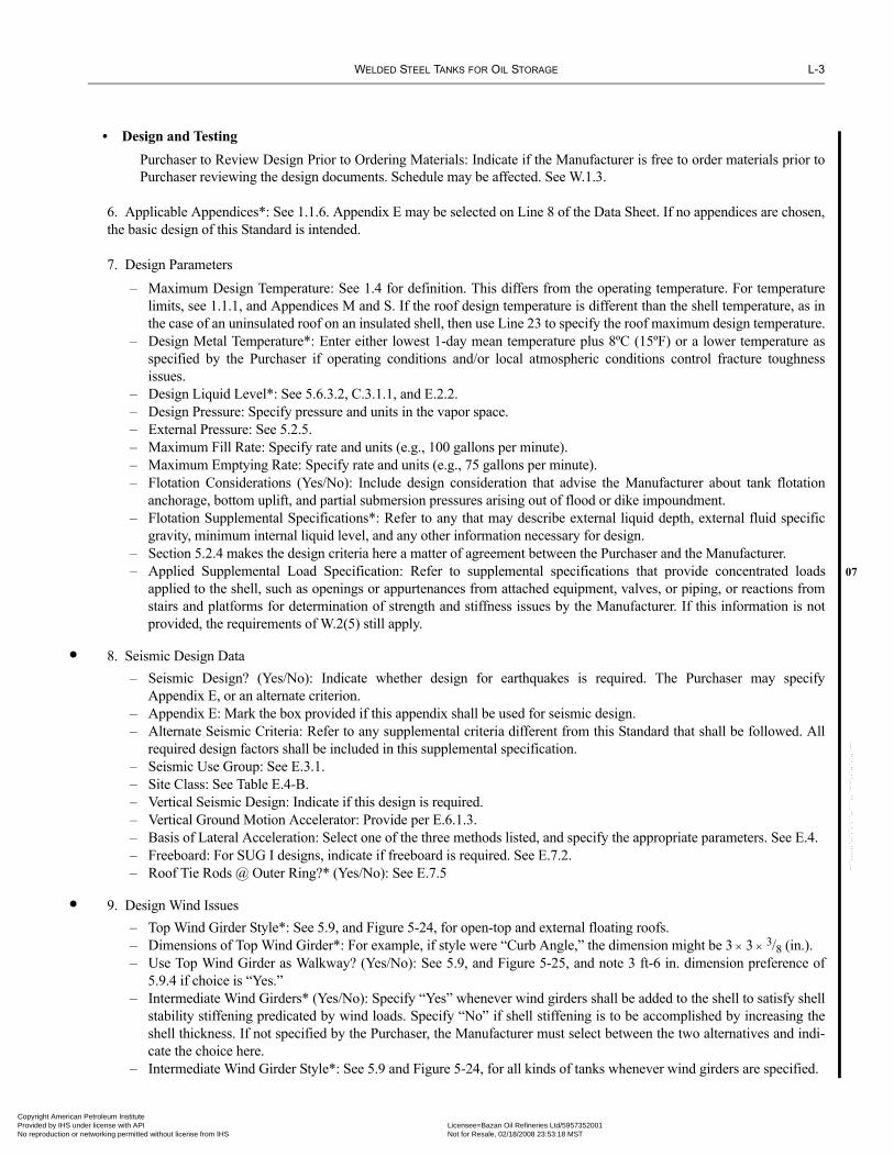
WELDED STEEL TANKS FOR OIL STORAGE L-3
07
•
•
Copyright AmericaProvided by IHS uNo reproduction o
--``,,,,,,`,,`,`,`,``,,````,,``-`-`,,`,,`,`,,`---
• Design and TestingPurchaser to Review Design Prior to Ordering Materials: Indicate if the Manufacturer is free to order materials prior toPurchaser reviewing the design documents. Schedule may be affected. See W.1.3.
6. Applicable Appendices*: See 1.1.6. Appendix E may be selected on Line 8 of the Data Sheet. If no appendices are chosen,the basic design of this Standard is intended.
7. Design Parameters– Maximum Design Temperature: See 1.4 for definition. This differs from the operating temperature. For temperature
limits, see 1.1.1, and Appendices M and S. If the roof design temperature is different than the shell temperature, as inthe case of an uninsulated roof on an insulated shell, then use Line 23 to specify the roof maximum design temperature.
– Design Metal Temperature*: Enter either lowest 1-day mean temperature plus 8ºC (15ºF) or a lower temperature asspecified by the Purchaser if operating conditions and/or local atmospheric conditions control fracture toughnessissues.
– Design Liquid Level*: See 5.6.3.2, C.3.1.1, and E.2.2.– Design Pressure: Specify pressure and units in the vapor space.– External Pressure: See 5.2.5.– Maximum Fill Rate: Specify rate and units (e.g., 100 gallons per minute).– Maximum Emptying Rate: Specify rate and units (e.g., 75 gallons per minute).– Flotation Considerations (Yes/No): Include design consideration that advise the Manufacturer about tank flotation
anchorage, bottom uplift, and partial submersion pressures arising out of flood or dike impoundment.– Flotation Supplemental Specifications*: Refer to any that may describe external liquid depth, external fluid specific
gravity, minimum internal liquid level, and any other information necessary for design. – Section 5.2.4 makes the design criteria here a matter of agreement between the Purchaser and the Manufacturer.– Applied Supplemental Load Specification: Refer to supplemental specifications that provide concentrated loads
applied to the shell, such as openings or appurtenances from attached equipment, valves, or piping, or reactions fromstairs and platforms for determination of strength and stiffness issues by the Manufacturer. If this information is notprovided, the requirements of W.2(5) still apply.
8. Seismic Design Data– Seismic Design? (Yes/No): Indicate whether design for earthquakes is required. The Purchaser may specify
Appendix E, or an alternate criterion.– Appendix E: Mark the box provided if this appendix shall be used for seismic design.– Alternate Seismic Criteria: Refer to any supplemental criteria different from this Standard that shall be followed. All
required design factors shall be included in this supplemental specification.– Seismic Use Group: See E.3.1.– Site Class: See Table E.4-B.– Vertical Seismic Design: Indicate if this design is required.– Vertical Ground Motion Accelerator: Provide per E.6.1.3.– Basis of Lateral Acceleration: Select one of the three methods listed, and specify the appropriate parameters. See E.4.– Freeboard: For SUG I designs, indicate if freeboard is required. See E.7.2.– Roof Tie Rods @ Outer Ring?* (Yes/No): See E.7.5
9. Design Wind Issues– Top Wind Girder Style*: See 5.9, and Figure 5-24, for open-top and external floating roofs.– Dimensions of Top Wind Girder*: For example, if style were “Curb Angle,” the dimension might be 3 × 3 × 3/8 (in.).– Use Top Wind Girder as Walkway? (Yes/No): See 5.9, and Figure 5-25, and note 3 ft-6 in. dimension preference of
5.9.4 if choice is “Yes.”– Intermediate Wind Girders* (Yes/No): Specify “Yes” whenever wind girders shall be added to the shell to satisfy shell
stability stiffening predicated by wind loads. Specify “No” if shell stiffening is to be accomplished by increasing theshell thickness. If not specified by the Purchaser, the Manufacturer must select between the two alternatives and indi-cate the choice here.
– Intermediate Wind Girder Style*: See 5.9 and Figure 5-24, for all kinds of tanks whenever wind girders are specified.
n Petroleum Institute nder license with API Licensee=Bazan Oil Refineries Ltd/5957352001
Not for Resale, 02/18/2008 23:53:18 MSTr networking permitted without license from IHS

L-4 API STANDARD 650
07
•
Copyright AmProvided by No reproduc
– Dimensions of Intermediate Wind Girders*: For example, if style were “formed plate,” dimension might be b = 30 in.per Figure 5-24.
– Check Buckling in Corroded Condition? (Yes/No): If “Yes,” the wind load shall be applied to the corroded shell (anoption covered in 5.9.7.1) to establish the adequacy of the thicknesses and/or stiffening rings to resist the applied forces.
10. Shell Design
– 1-Foot Method?* (Yes/No): The Purchaser may select this shell thickness design method. The method is subject to theapplicable limitations noted in 5.6.3, A.4, J.3.3, and S.3.2. If not selected by the Purchaser, the Manufacturer may selecteither this design method or one of the other two methods that this Standard lists, subject to the restrictions of this Stan-dard and the Purchaser’s approval.
– Variable-Design-Point Method?* (Yes/No/Alternate): The Purchaser may select this shell thickness design method.This method is subject to the restrictions detailed in 5.6.4. If the 1-Foot Method or Elastic Analysis Method is selectedby the Purchaser and the Variable-Design-Point Method is also selected as an “Alternate” by the Purchaser, the Vari-able-Point Design Method may be used in addition to the Purchaser-selected method, but the resulting proposal mustbe clearly marked as an “Alternate.” If the method is not selected by the Purchaser, the Manufacturer may select eitherthis design method or one of the other two methods that this Standard lists, subject to the restrictions of this Standardand the Purchaser’s approval.
– Elastic Analysis Method?* (Yes/No/Alternate): The Purchaser may select this shell thickness design method. Thismethod is subject to the restrictions detailed in 5.6.5. Cases when this method is mandatory are named in 5.6.5 as wellas requirements on the analysis boundary conditions. When it is not mandatory, the Purchaser may select this shelldesign method. If the 1-Foot or Variable-Design-Point Method is selected by the Purchaser and the Elastic AnalysisMethod is also selected as an “Alternate” by the Purchaser, the Elastic Analysis Method may be used in addition to thePurchaser-selected method, but the resulting proposal must be clearly marked as an “Alternate.” If the method is notselected by the Purchaser, the Manufacturer may select either this design method or one of the other two methods thatthis Standard lists, subject to the restrictions of this Standard and the Purchaser’s approval.
– Plate-Stacking Criteria* Centerline-Stacked? (Yes/No) or Flush-Stacked on the Inside or Outside? (Yes/No)?: – Plate Widths (Shell Course Heights) and Thicknesses*: Specify nominal shell course heights and thicknesses. The first
course is attached to the bottom.– Joint Efficiency*: Specify in percentage. Applicable only to Appendices A, J, and S designs. Mark “NA” for all other
designs.– Shell-to-Bottom Weld Type*: See Figure 5-3A (inside and outside corner fillets), Figure 5-3C (inside and outside
partial penetration corner welds with fillet weld reinforcement), and J.3.2.4 (full penetration butt weld to flangedflat bottom).
– Shell-to-Bottom Weld Inspection Method*: Choose among the options listed in accordance with 7.2.4.
11. Open-Top and Fixed-Roof Data (see page 6 of the Data Sheet for Floating Roofs)
– Open Top?* (Yes/No) Specify “Yes” if tank has no fixed roof or has an external floating roof. Specify “No” for allother tanks.
Note: The remaining entries in this line apply to fixed roofs ONLY:
– Fixed Roof Type*: Enter description, such as supported cone with internal structure, supported cone with externalstructure, structurally-supported aluminum geodesic dome, self-supporting cone, self-supporting dome, self-supportingumbrella, flanged only flat top, or other. See 5.10.1 or Appendix G.
– Roof Support Columns*: Specify pipe or structural shape. If structural shape is specified, indicate the kind (e.g., wideflange, back-to-back channel, etc.).
Commentary: Pipe-type roof columns are preferred for internal floating roof tanks. In many cases the openings are 3/4 NPTthreaded couplings that allow the user to plug the openings when the tank is in service, to minimize corrosion of the sup-ports and reduce emission from the tank. The openings are needed to allow the free drainage and cleaning of the columnswhen the tank is out of service.
– Cone Slope*: Specify rise to run as a dimensionless ratio, e.g., “3/4:12”. – Dome or Umbrella Radius*: See 5.10.6 for self-supporting approximate spherical radius of roof.
•
--``,,,,,,`,,`,`,`,``,,````,,``-`-`,,`,,`,`,,`---
erican Petroleum Institute IHS under license with API Licensee=Bazan Oil Refineries Ltd/5957352001
Not for Resale, 02/18/2008 23:53:18 MSTtion or networking permitted without license from IHS

WELDED STEEL TANKS FOR OIL STORAGE L-5
07
•
•
Copyright AmericaProvided by IHS uNo reproduction o
--``,,,,,,`,,`,`,`,``,,````,,``-`-`,,`,,`,`,,`---
– Weld Joints*: Describe the type of roof plate weld joint, which may be lap joint, butt joint, or some combinationthereof.
Note: Appendix F, Section F.7 roofs shall conform to API Std 620.
– Seal Weld Underside of Lap Joints? (Yes/No): May be required for internally coated roof plates or to prevent crevicecorrosion.
– Seal Weld Underside of Wind Girder Joints? (Yes/No): See 5.1.5.8.– Gas-tight? (Yes/No): See 7.3.7.– Joint Efficiency*: Use only for Appendix F, Section F.7 roofs. See API Std 620, Table 3-2.– Thickness*: Provide nominal thickness of roof plates.– Snow Load*: Purchaser to provide the snow load for non-U.S. Sites. For non-US sites, the Manufacturer should indi-
cate the 50-year ground snow load selected. See 5.2.1e. For instructions on combining loads, see 5.10.2.1.– Applied Supplemental Loads Specification*: Indicate supplementary specifications for both dead and live roof loads
that are concentrated or have local distributions (e.g., the personnel loads of 5.8.6.2 and H.4.2.2). Specify any reactionsfrom platforms or walking surfaces as well as loads applied by equipment, valves, and piping.
– Column Lateral Load: Purchaser may optionally specify lateral loads imposed upon roof-supporting columns in accor-dance with 5.10.2.9.
– Venting Devices*? Enter type and quantity of devices for normal venting per API Std 2000, and pressure settings. Also,enter type(s) and quantity of emergency venting devices that meet either API Std 2000, circulation venting per Appen-dix H, or a frangible roof design per 5.10.2.6, as applicable. The frangibility of tanks less than 50 ft in diameter mayrequire additional design considerations beyond those required by this Standard.
– For Non-Frangible Roofs:– Seal Weld Roof Plates to Top Angle on the Inside? (Yes/No): When “Yes” is selected, the shell-to-roof-joint
shall be seal-welded on the inside. For certain designs, this may adversely affect frangibility.– Weld Rafters to Roof Plates? (Yes/No):
– Roof-to-Shell Detail*: See Figures 5-3A and F-3, J.3.5, and API Std 620, Figure 3-6.– Radial Projection of Horizontal Component to Top Angle*: Specify inward or outward projection.
12. Required Bottom Data– Thickness*: Enter nominal thickness, including corrosion allowance.– Style*: Enter one of the following: flat, cone up to center, cone down to center, side to side (tilted plane), cone down to off-
center. Enter all sump requirements (number, size, location, etc.) in Data Sheet (Table 3, Line 23, or on the Tank Plan). – Slope*: Enter rise versus run. For the off-center style above, the slope specified is the maximum slope.– Weld Joint Type*: Enter one of the following: single-welded full-fillet lap joint, single-welded butt with backing strip
that remains in place, double-welded butt without backing strip, double-welded full-fillet lap joints, or other, to bedetailed on Data Sheet Line 23 if necessary.
– Provide Drip Ring (Yes/No): If required, a drip ring shall be provided per 3.4.5. Unless the following Alternate Speci-fication is provided, the default drip ring shall be provided.
– Alternate Specification: Refer to an acceptable drip ring design specification if the Purchaser requires a drip ring butdeclines the default design of 5.4.5.
– Annular Ring* (Yes/No): The Purchaser may stipulate this type of detail even if not required by this Standard. A Pur-chaser’s choice of “No” does not relieve the Manufacturer from complying with the requirements of this Standard inthis regard.
– Annular Ring Minimum Radial Width* and Thickness*: Specify width and thickness.
13. Foundation Information– Furnished by*: Indicate Purchaser, Manufacturer, or others.– Type*: Indicate materials and form. See Appendices B and I (e.g., concrete ring-wall or steel wide flange grillage on
concrete pile cap).– Soil Allowable Bearing Pressure*: Estimate pressure from geotechnical report, experience with similar tanks in the
same area, etc.– Per Specification*: Refer to any specification that describes soil allowable bearing pressure.– Anchor Size*: See 5.3.1.1 and 5.12. Provide materials of construction, geometric forms, and corrosion allowance for
anchors in Table 2 of the Data Sheet.
n Petroleum Institute nder license with API Licensee=Bazan Oil Refineries Ltd/5957352001
Not for Resale, 02/18/2008 23:53:18 MSTr networking permitted without license from IHS

L-6 API STANDARD 650
•
07
•
Copyright AmProvided by No reproduc
--``,,,,,,`,,`,`,`,``,,````,,``-`-`,,`,,`,`,,`---
– Anchor Quantity*: Indicate the total number of anchors or anchor bolts to be provided.– Foundation Design Loads: See W.3(15). These loads are unfactored after the manner of the Allowable Stress Design
methodology. (Sign convention is as follows: positive acting downward, negative acting upward.)– Base Shear*: Indicate the values for the wind and seismic conditions in units of force.– Overturning Moment*: Indicate in units of force-distance. See 5.11 for wind, and Appendix E, or alternate
seismic criteria as specified on Line 8 of the Data Sheet, for seismic criteria.– Ring Forces*: Indicate loads delivered by the shell in units of force per circumference of shell.Note: The uniformly distributed loads are shell plus roof weight (both new and corroded), roof live load, internal pressure, andpartial vacuum.
Note: The non-uniform loads are the peak magnitudes of the longitudinal compressive distributed force derived from the windand seismic-overturning moments without regard to any other compressive or tensile loads in the shell.
– Bottom Forces*: Indicate support loads that are the uniformly applied forces to the bottom away from the shellring in units of force per unit area. These include weight of bottom plates, product and test liquid weights, andpressure/vacuum loads. Mark all inapplicable entities as “NA.”
– Other Foundation Loads*: Provide an attachment to describe these loads such as lateral soil pressure, overbur-den, roof column reactions, pore pressure, uplift anchor forces, etc.
– Minimum Projection of Foundation Above Grade: Specify the minimum required projection of the foundationabove grade, if any.
14. Pressure Test (See 7.3.5)
– Responsibility for Heating Test Water, if Required: Select one.– Hydro-Test Fill Height*: See 7.3.5, F.4.4, and F.7.6.– Settlement Measurements (Yes/No): Purchaser may waive the measurement of foundation settlement during the hydro-
test in accordance with 7.3.6.5.– Extended Duration of Hydro-Test: Provide the number of hours or days if the tank is to be kept full of water for an
extended period.– Predicted Settlement Profile is Attached: Check if the Purchaser elects to inform the Manufacturer of relevant settle-
ment predictions. – Responsibility for Setting Water Quality: Specify party responsible for setting water quality standards. Refer to supple-
mental specifications as required. For guidance, see 7.3.6.3.– Test Water Source and Disposal Tie-In Locations: Provide the location of the supply and disposal points for hydro-test
water that the Manufacturer shall use.– Test Requirements for Appendix J Tanks: Hydrostatic Testing (Yes/No): If “No” is selected, the Purchaser must specify
the required Alternative Test from J.4.2.2.– Penetrant Testing Allowed in lieu of Hydro-Testing: Check if there is no means of providing test water at the tank site,
e.g., very remote tank sites. See 7.3.5.– Post-Pressure-Test Activities Required of the Manufacturer: Select the activities desired according to 7.3.6.2(4).
15. Optional Fabrication, Erection, Inspection, and Testing Requirements
– Inspection by: Designate Purchaser’s inspectors. See 7.3.1.1.– Supplemental NDE (Non Destructive Examination) Responsibility and Supplemental NDE Specifications: Specify
NDE options (e.g., see 8.3.5) or indicate additional NDE options, such as weld hardness testing or additional radio-graphs. For possible additional responsibilities, see 7.3.2.3.
– Positive Material Identification (Yes/No): Include criteria to be followed.– Maximum Permissible Plate Thickness for Shearing: Specify the thickest plate to be butt-welded that may be sheared
in accordance with 6.1.2.– Must Welds not exceeding 6 mm (1/4 in.) or welds greater than 6 mm (1/4 in.) be Multi-Pass? (Yes/No): See 5.1.3.6– Leak Test Method*: Describe leak tests for each component. For example, see 7.3.3, 7.3.4, 7.3.5, 7.3.7, C.3.6, and H.6.2.– Modify or Waive API Dimensional Tolerances (see 7.5)? (No/Yes/Specify): If the API tolerances are not adequate,
specify the required tolerances here.– Specify Additional Tolerances, if any, and Circumferential and Vertical Measurement Locations: Indicate any supplemen-
tal tolerances for plumbness and roundness, giving the tolerance limit and the locations for the tolerance readings.
erican Petroleum Institute IHS under license with API Licensee=Bazan Oil Refineries Ltd/5957352001
Not for Resale, 02/18/2008 23:53:18 MSTtion or networking permitted without license from IHS

WELDED STEEL TANKS FOR OIL STORAGE L-7
•
•
•
07
•
•
•
••
Copyright AmericaProvided by IHS uNo reproduction o
Note: If Additional Radial Tolerance measurements are specified, radial tolerances measured higher than 0.3 m (1 ft) above the shell-to-bottom weld shall be three times the tolerances given in 7.5.3, unless specified otherwise by the Purchaser.
16. Coating Data
– Internal Coatings by: Describe responsible party or indicate “Not Req’d.”– Per Specification*: Refer to supplemental specifications to address the detailed coating/galvanizing requirements for
items such as internal structural supports, inside surface of roof, bottom, piping flanges, stairs, platforms, ladders,underside of bottoms, and top surface of foundation. Ensure that all requirements address issues such as joint contourpreparation (e.g., shell-to-bottom, sharp edges of laps, crevices, etc.) and reduced weld build-up or undercut. For guid-ance on internal bottom coatings, see API RP 652.
– External Coating by: Describe responsible party or indicate “Not Req’d.”– Per Specification*: Refer to any supplemental specification fully describing the process.– Under-Bottom Coating by: Describe responsible party or indicate “Not Req’d.”– Per Specification*: Refer to a supplemental specification fully describing the process.
17. Cathodic Protection
– Cathodic Protection System? (Yes/No): See API RP 651 for guidance.– Per Specification*: Describe requirements and responsible parties.
18. Leak Detection System
– Leak Detection System? (Yes/No): Provide a passive leak detection system as described in Appendix I. Active ele-ments may be specified; however, the system must also provide leak detection by passive means. If active leak detec-tion schemes (e.g., volumetric inventory records, mass change, acoustic emissions sensing, and tracer elementdetection) are required, describe the requirements by means of a specification herein.
– Per Specification*: Describe requirements and responsible parties.
19. Release Prevention Barrier (See Appendix I, I.1.1, Note, for definition.)
– Release Prevention Barrier? (Yes/No): Examples of barriers are vault floors, double bottoms, and impermeable mem-branes.
– Per Specification*: Describe requirements and responsible parties.
20. Tank Measurement System
– Required? (Yes/No): Examples are float gauge, differential pressure level indicator, level alarm, radar, and level gauge.– Remote Capability Required? (Yes/No): Indicate whether level measurements are required to be relayed to remote con-
trol stations.– By*: Designate the provider of the measurement system.– Per Specification*: Refer to supplemental specification.
21. Tank Weights and Lifting Requirements
– Full of Water*: Indicate weight filled with water to design liquid level. – Empty*: Indicate weight when empty. For specification of lift lugs, see Data Sheet, Line 28. For tanks that are to be
lifted, rigging and handling instructions and temporary bracing may be required. Provide reference to a supplementalspecification as required.
– Shipping*: Specify weight for Appendix J tanks only.– Brace/Lift Specification*: Refer to any supplemental bracing/lifting specifications.
22. References: Include relevant documents.
23. Remarks: Use this for issues not adequately covered elsewhere. Include any alternate shell opening designs specified bythe Purchaser in accordance with 5.7, with reference to the alternate criteria (e.g., API Std 620).
--``,,,,,,`,,`,`,`,``,,````,,``-`-`,,`,,`,`,,`---
n Petroleum Institute nder license with API Licensee=Bazan Oil Refineries Ltd/5957352001
Not for Resale, 02/18/2008 23:53:18 MSTr networking permitted without license from IHS

L-8 API STANDARD 650
•
•
•
07
Copyright AmProvided by No reproduc
--``,,,,,,`,,`,`,`,``,,````,,``-`-`,,`,,`,`,,`---
Table 1 Materials of Construction
List material specifications (e.g., CSA G40.21M-260W, ASTM A573-65, ISO 630 Gr E355-C, etc.), and supplied thickness ofitems in the left column only.State corrosion allowance for each component. See 5.3.2. For internals, indicate if the corrosion allowance is to be applied to eachexposed surface. Unless indicated otherwise, it applies to the total thickness specified. Show units of measure.Any materials that either have received any heat treatment, such as normalizing, beyond the minimum heat-treating requirementsof the material specification or have been qualified by impact tests shall be identified by reference to notes located under the“remarks” lines. The notes shall define the heat treatment received and/or the energy acceptance levels, test temperature, andspecimen orientation for impact tests.When thermal stress relief is applied to a part in accordance with the requirements of 5.7.4, the part shall be identified by a noteunder the “remarks” lines.
Table 2 Bolts and Anchors
Complete all bolting and anchorage information (see 4.7, 5.11.3, 5.12, E.6.2, E.7, F.7.4, and J.3.9), including head and nut shapeand material specifications. Show units of measure for the corrosion allowance and see 5.3.2. Corrosion allowance may bemarked “NA” for galvanized, special corrosion-resistant coated, or stainless steel anchor bolts.
Table 3 Nozzle and Manhole Schedule* (for Fixed Roof, Shell, and Bottom)
Include nozzles (e.g., both blanked and piped-to connections), equipment and instrument attachment and access openings, sumps,inspection ports, and manholes in the fixed roof, shell and bottom.The description of, and examples for, the information that may be specified in Table 3 is as follows:
ASME B16.47 flanges are not available in all sizes, materials, and flange types (see 5.7.6.1).Nozzle projections shall be measured from the outside of the shell to the face of the shell flange (FF) and from datum line to theface of the flange for roof and floor openings, unless otherwise specified. Shell opening elevations shall be from the datum line tothe centerline of the opening, unless otherwise specified. Roof opening locations shall be measured radially from the centerline ofthe tank. Specify datum line and elevations with orientations on the “Tank Plans and Sketch” of the Data Sheet.For fabricated flanges requiring ASME Boiler and Pressure Vessel Code, Section VIII, Division 1, UG-34 and Appendix 2 calcu-lations, place the “m” and “y” values for the gasket in the “Remarks” section of the Data Sheet, Line 23. Clearly indicate to whichgaskets these values apply.Consider listing in Table 3, items such as:
• Water draw-offs.• Thermowells (make, model, stem length).• Suction trough (size, reference drawing).
Entry Field Comments Representative Example
Mark Purchaser’s mark or designation Nozzle “A-1” in shell
Service Stated service or purpose Product Out
Size, NPS, or Diameter (In.) Conventional size description of pipe and tube NPS 24
Neck Schedule or Wall Thickness Pipe schedule or wall thickness Sch 40S
Reinf. Plate Dimensions Circular, Diamond, etc. 49.5" OD × 0.188"
Full Pen. On Open. (Y/N) See 5.7.2.2 Yes
Flange Type Fabricated, S.O., WN, LJ, etc. ASME B16.5 Lap Joint
Flange Class or Thickness ASME, ANSI, API Std 650 Table Cl 150
Gasket Bearing Surface Dimensionand Finish
Dimension and finish of bearing surface in contact with gasket
27.25" OD, 125-250 Ra μ-in
Gasket Thickness and Dimension 0.125" × 24" ID × 28.25" OD
Gasket Material and Description Generic, Brand, ANSI Std, etc. Non-asbestos sheet, per Manufacturer
Proj. to FF or CL or from Datum Lines See paragraph below 18" FF
erican Petroleum Institute IHS under license with API Licensee=Bazan Oil Refineries Ltd/5957352001
Not for Resale, 02/18/2008 23:53:18 MSTtion or networking permitted without license from IHS
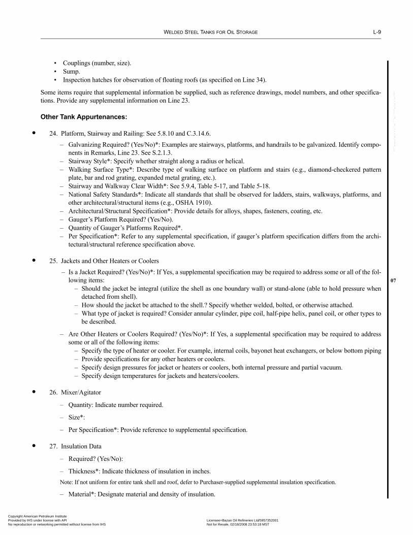
WELDED STEEL TANKS FOR OIL STORAGE L-9
•
•07
•
•
Copyright AmericaProvided by IHS uNo reproduction o
--``,,,,,,`,,`,`,`,``,,````,,``-`-`,,`,,`,`,,`---
• Couplings (number, size).• Sump.• Inspection hatches for observation of floating roofs (as specified on Line 34).
Some items require that supplemental information be supplied, such as reference drawings, model numbers, and other specifica-tions. Provide any supplemental information on Line 23.
Other Tank Appurtenances:
24. Platform, Stairway and Railing: See 5.8.10 and C.3.14.6.
– Galvanizing Required? (Yes/No)*: Examples are stairways, platforms, and handrails to be galvanized. Identify compo-nents in Remarks, Line 23. See S.2.1.3.
– Stairway Style*: Specify whether straight along a radius or helical.– Walking Surface Type*: Describe type of walking surface on platform and stairs (e.g., diamond-checkered pattern
plate, bar and rod grating, expanded metal grating, etc.).– Stairway and Walkway Clear Width*: See 5.9.4, Table 5-17, and Table 5-18.– National Safety Standards*: Indicate all standards that shall be observed for ladders, stairs, walkways, platforms, and
other architectural/structural items (e.g., OSHA 1910).– Architectural/Structural Specification*: Provide details for alloys, shapes, fasteners, coating, etc.– Gauger’s Platform Required? (Yes/No).– Quantity of Gauger’s Platforms Required*.– Per Specification*: Refer to any supplemental specification, if gauger’s platform specification differs from the archi-
tectural/structural reference specification above.
25. Jackets and Other Heaters or Coolers
– Is a Jacket Required? (Yes/No)*: If Yes, a supplemental specification may be required to address some or all of the fol-lowing items: – Should the jacket be integral (utilize the shell as one boundary wall) or stand-alone (able to hold pressure when
detached from shell). – How should the jacket be attached to the shell.? Specify whether welded, bolted, or otherwise attached. – What type of jacket is required? Consider annular cylinder, pipe coil, half-pipe helix, panel coil, or other types to
be described.
– Are Other Heaters or Coolers Required? (Yes/No)*: If Yes, a supplemental specification may be required to addresssome or all of the following items: – Specify the type of heater or cooler. For example, internal coils, bayonet heat exchangers, or below bottom piping – Provide specifications for any other heaters or coolers. – Specify design pressures for jacket or heaters or coolers, both internal pressure and partial vacuum. – Specify design temperatures for jackets and heaters/coolers.
26. Mixer/Agitator
– Quantity: Indicate number required.
– Size*:
– Per Specification*: Provide reference to supplemental specification.
27. Insulation Data
– Required? (Yes/No):
– Thickness*: Indicate thickness of insulation in inches.Note: If not uniform for entire tank shell and roof, defer to Purchaser-supplied supplemental insulation specification.
– Material*: Designate material and density of insulation.
n Petroleum Institute nder license with API Licensee=Bazan Oil Refineries Ltd/5957352001
Not for Resale, 02/18/2008 23:53:18 MSTr networking permitted without license from IHS

L-10 API STANDARD 650
•
•07
•
•
Copyright AmProvided by No reproduc
– Per Specifications*: Provide references to insulation and insulation support specifications.
– Responsibility for Insulation and Installation: Indicate Purchaser, Manufacturer, or others.
28. Structural Attachments
– Lift Lugs for Maintenance or Installation?* (Yes/No): Specify projection if insulation is required.
– Description*: Describe the type of lifting lugs required.
– Shell Anchorage?* (Yes/No): Wind or seismic loading may require anchorage. See 5.11, 5.12, and Appendices E and F.
– Type*: Specify type of shell anchorage (e.g., chairs, lugs, sleeves, rings, straps, etc.).
– Scaffold Cable Supports? (Yes/No): Indicate if required. See Figure 5-22.
29. Various Other Items
– Flush-Type Shell Connection and Flush-Type Cleanout Fitting: Mark the blocks indicating which type(s) is required.See Figures 5-12 and 5-14.
– Waive Application of Appendix P: Indicate if the Manufacturer is required to analyze nozzle loads in accordance withAppendix P. It is not intended that this appendix necessarily be applied to piping connections similar in size and config-uration to those on tanks of similar size and thickness for which satisfactory service experience is available. SeeAppendix P for limitations.
– Enter miscellaneous items not found elsewhere on the Data Sheet.
Table 4 Other Tank Appurtenances Schedule*:
Include all appurtenances not described elsewhere on the Data Sheet.Consider listing in Table 4 such items as the following:
- Ladders
- Overflow openings (number and size). See H.5.3.
- Circulation vents (number and size). See H.5.2.2.
- Pressure-vacuum relief valves (nominal size, model number, etc.).
- Free vent/flame arrestor.
- Grounding clips (quantity and style).
Some items require supplemental information, such as reference drawings, model numbers, and other specifications. Pro-vide any supplemental information on Line 23.
Floating Roof Data:
30. Floating Roof Selection
– Design Basis: Check which API Appendix is to be applied?
– Type of Roof*: Specify the option listed in Appendix C or H. Only the Purchaser may specify “Other” and describeanother option.
31. Seals
– Primary Seal: Select from types listed, or specify “Other” and supply necessary details or reference specification. Foamseal material may absorb some products over time, becoming a potential safety issue. See C.3.13 and H.4.4.
– Shoe Mechanism: Indicate mechanism required for mechanical primary seal. Select the Manufacturer’s standard, orspecify a particular type (e.g., pantograph, leaf spring, safety-pin spring, coil spring scissors, etc.).
•
--``,,,,,,`,,`,`,`,``,,````,,``-`-`,,`,,`,`,,`---
erican Petroleum Institute IHS under license with API Licensee=Bazan Oil Refineries Ltd/5957352001
Not for Resale, 02/18/2008 23:53:18 MSTtion or networking permitted without license from IHS

WELDED STEEL TANKS FOR OIL STORAGE L-11
••
07
Copyright AmericaProvided by IHS uNo reproduction o
– Electrically Isolate Mechanism from Shoes? (Yes/No): Indicate if required to insulate to prevent possible arcing.
– Wax Scrapers Required? (Yes/No): Such devices remove wax-like substances from the tank shell as the roof descendsto provide a cleaner sealing surface.
– Minimum Shoe Thickness*: Include units. See C.3.13 and H.4.4.4.
– Carbon Steel Shoes to be Galvanized? (Yes/No): This option cannot be selected for stainless steel shoes.
– Secondary Seal: Indicate the need for a secondary seal.
– Supplementary Specification: Refer to supplementary specification for secondary rim seal.
32. Data for All Floating Roofs:
– Overflow Openings in Shell Acceptable? (Yes/No): See C.3.1.1.
– Shell Extension? (Yes/No): Select a windskirt per C.3.1.1. If Yes is selected, this may affect capacity, design liquidlevel, and the need for an overflow indicator (alarm), requiring a Purchaser-supplied supplemental specification underLine 20. See API RP 2350.
– Roof-Drain Check Valves Required? (Yes/No): See C.3.8.1.
– Roof-Drain Isolation Valves Required? (Yes/No): See C.3.8.1.
– Freeze Protection for Roof Drains Required? (Yes/No): See C.3.8.1. Freeze protection is not required in all climates.
– Roof-Drain Piping to External Nozzles: Select the type of piping from the blocks provided. If “Other” is selected, pro-vide description or reference supplemental specification. The number of roof drains required and sump details shall beshown on the construction drawings.
– Foam Dam? (Yes/No): See C.3.15.2.
– Supplementary Specification: Provide supplementary foam dam specification reference.
– Minimum Deck Thickness*: Specify a minimum deck thickness greater than that stated in C.3.3.2. If not specified, theManufacturer shall insert the thickness stated in the above reference.
– Bulkhead Top Edges to be Liquid-Tight? (Yes/No): See H.4.1.8. This is mandatory for external floating roofs but is aPurchaser’s option for internal floating roofs.
– Seal-Weld Underside of Roof?: Select “Yes” to provide increased corrosion protection or additional stiffness. Thisapplies to seal welds in addition to the seal welding required in C.3.3.3 and H.4.3.5.
– Electrical Bonding: Indicate if either shunts or cables will be used to bond the roof electrically to the shell, and providea supplemental specification to designate any technical requirements.
– Quantity of Non-Guide Pole Gauge Wells Required: See C.3.14.1(2), for manual gauging apparatus in wells not asso-ciated with a guide pole.
– Quantity of Sample Hatches Required: See C.3.15.3 for sample hatches without gauging apparatus.
– Guide Pole for Gauging? (Yes/No): Indicate whether the guide pole (anti-rotation device) shall be used for gauging.
– Slots in Guide Pole? (Yes/No): Indicate whether guide pole, if used for gauging, shall be slotted.
– Datum Plates? (Yes/No): Indicate if required. See C.3.14.4.
– Striking Plates? (Yes/No): Indicate if required. See C.3.14.5.
– Guide Pole Emissions-Limiting Devices: Indicate any required by regulation or any additional devices requested by thePurchaser for guide poles from the list provided. See C.3.14.1(1).
– Quantity of Roof Manholes*: See C.3.5, C.3.11, and H.5.5.--``,,,,,,`,,`,`,`,``,,````,,``-`-`,,`,,`,`,,`---
n Petroleum Institute nder license with API Licensee=Bazan Oil Refineries Ltd/5957352001
Not for Resale, 02/18/2008 23:53:18 MSTr networking permitted without license from IHS

L-12 API STANDARD 650
•
07
•
Copyright AmProvided by No reproduc
– Minimum Roof Clearances Above Bottom: Indicate elevations above the bottom to the landed floating roof for boththe minimum operating level and the minimum maintenance level. These choices affect access and capacity. SeeC.3.10.3, H.4.6.2, and API RP 2350.
– Removable Leg Storage Racks? (Yes/No): Indicate if required. For internal floating roofs with leg supports, specifywhether a storage rack is required. For external floating roofs, the storage rack is required per C.3.10.1.
– Leg Sleeves or Fixed Low Legs: Mark the block that specifies whether the leg-supported floating roof shall be pro-vided with a sleeve through the roof plate or with fixed low legs.
33. Additional Data for External Floating Roofs (See Appendix C):
– Weather Shield? (Yes/No): Indicate the need for a weather shield on external floating roofs. If secondary rim sealsserve as weather shields, they shall not be additionally requested here.
– Supplementary Specification: Provide references for weather shield specifications.
– Rolling Ladder Required?* (Yes/No): Unless the Purchaser specifically declines here, a rolling ladder is to be providedin accordance with C.3.7.
– Must Each Leg be Field-Adjustable? (Yes/No): Indicate if required. If potential bottom settlement is an issue, the Pur-chaser has the option to require a two-position removable leg that can accommodate local adjustments that may differfor each leg. This option is for all floating roofs and is specifically discussed in C.3.10.3.
– Design Rainfall Intensity: Specify a rainfall rate, a minimum period of duration, and an association with a statisticallyoccurring storm such as that found in Technical Report No. 40 (e.g., 0.5 in. per hour for 5 minutes for the 2-year storm).
– Design Accumulated 24-hour Rainfall: Specify height of water accumulated in 24 hours associated with a statisticallyoccurring storm (e.g., 12 in. in 24 hours for the 100-year storm). See C.3.4 for minimum requirements.
– Distortion and Stability Determinations Required? (Yes/No): List option per C.3.4.2.
– Supplemental Specification: Document any established methodology chosen by agreement between the Purchaser andthe Manufacturer.
– Landed Live Load*: See C.3.10.2. This space gives the Purchaser the option of specifying a larger live load for exter-nal floating roofs and for specifying the stated live load for internal floating roofs even if drains are provided that maynormally negate the need for such live load design.
34. Additional Data for Internal Floating Roofs
– Two-Position Legs Required? (Yes/No): See H.4.6.2. If the two positions shall be field-adaptable to account for bottomsettlement, indicate this in Line 23 of the Data Sheet.
– Cable-Supported Floating Roof? (Yes/No): Indicate if required. This is an internal floating roof option as found inH.4.6.5.
– Fixed-Roof Inspection Hatches Required? (Yes/No): Indicate number required for evaluation of condition of floatingroof without having to enter the vapor space. See H.5.5.3.
– Internal Roof Drain Required? (Yes/No): See H.4.1.10
– Omit Distribution Pads Supporting Uniform Live Loads? (Yes/No): See H.4.6.6
– Corrosion Gauge Required? (Yes/No): See H.5.8.
– Fixed Ladder Required? (Yes/No): This applies to vertical ladders attached to the shell, which will also require a man-hole in the fixed roof to be specified in Table 3.
– Modified Minimum Point Load? (Yes/No): Point or concentrated loads are stated in H.4.2.2 for internal floating roofs,but may be waived for tanks 9 m (30 ft) or smaller in diameter.
--``,,,,,,`,,`,`,`,``,,````,,``-`-`,,`,,`,`,,`---
erican Petroleum Institute IHS under license with API Licensee=Bazan Oil Refineries Ltd/5957352001
Not for Resale, 02/18/2008 23:53:18 MSTtion or networking permitted without license from IHS

WELDED STEEL TANKS FOR OIL STORAGE L-13
•
•
07
Copyright AmericaProvided by IHS uNo reproduction o
--``,,,,,,`,,`,`,`,``,,````,,``-`-`,,`,,`,`,,`---
– Mfr. to Leak Test Compartments: Indicate the % of compartments to be tested by the Manufacturer and the location ofthe tests. If unknown prior to the Purchaser doing a field inspection, special contract terms may be required to cover theadditional costs.
– Roof Erector’s Flotation Test: Indicate when this test is to be performed: See H.6.5, H.6.6 for restrictions on theseoptions.
– Flotation Test Media: Indicate the media to be used and the water quality. See H.6.6. Provide a separate specification, ifrequired, to stipulate requirements.
– Flotation Test Duration, Fill Height,: See H.6.6.
– Flotation Test Items provided by Purchaser: List any items being supplied including those (gaskets, fasteners, testblanks, etc.) after the test is completed. See H.6.6.
– Responsible Party for Conducting Flotation Test and Inspecting Roof during Test: Purchaser can delegate these. SeeH.6.6.
Table 5 Floating Roof Materials
According to C.3.1.2, the application of corrosion allowances (C.A.) shall be a matter of agreement between the Purchaserand the Manufacturer. Document this agreement on the Data Sheet “Remarks” Line 23 (e.g., “Manufacturer affirms thatthe nominal thicknesses chosen for floating roof components include the corrosion allowances shown in the Table forFloating Roof Materials on page 7 of the Data Sheet”).
L.3.2 TANK PLAN AND SKETCHES (PAGE 8 AND SUPPLEMENTS)
L.3.2.1 General
Page 8 of the Data Sheet shall be used to show the shell and roof appurtenance orientations. A single sheet is normally adequatefor this purpose; however additional sheets may be necessary to show special details or configurations. All sheets shall be identi-fied and sequenced as part of the Data Sheet. Sketches may be made with CAD or manual drafting. All sheets shall be identifiedby revision date or other means of record change.
Note: Consider the prevailing wind direction when locating equipment requiring personnel access.
L.3.2.2 Sketch Views
The sketch view shall include an orthographic “Plan View” that may be used for the orientation of shell, roof, and bottom open-ings. Other views may be added.
L.3.2.3 Drafting Practices for Data Sheet Sketches
Drafting practices shall be consistent with the following items:• Where practicable, sketches shall be to scale, but the scale need not be shown on the sketches.• Bottom views are not allowed.• Plant north or geographic north arrow shall point upward on the sketch.• Plant north or geographic north shall be at the “0 degrees” orientation, as applicable.• Component thicknesses need not be shown on the sketch.• Internal details shall be identified and located. Provide only enough information to describe the item, or provide reference to
standard details. These items shall also be itemized in the appropriate tables in the Data Sheet.• External appurtenances may be omitted from the sketch; however they must be itemized in the appropriate tables in the
Data Sheet.• Foundation or anchorage details not clearly defined elsewhere shall be shown in the Data Sheet. This may require that an
“Elevation View” be provided.
n Petroleum Institute nder license with API Licensee=Bazan Oil Refineries Ltd/5957352001
Not for Resale, 02/18/2008 23:53:18 MSTr networking permitted without license from IHS

L-14 API STANDARD 650
07
Copyright AmProvided by No reproduc
API API Std 650 Storage TankData Sheet
Data Sheet Status: ____________________
Page 1 of 8
* For boxes marked with *, if blank, Mfr. shall determine and submit as per Appendix L. For all lines, see Appendix L for line-by-line instructions.
GENERAL Special Documentation Package Requirements: ____________________________
Measurement Units to be used in API Std 650: SI US Customary
1. Manufacturer* _________________________ Contract No.* _________________
Address* _______________________________________________________________________________________________
Mfg. Serial No.* ____________________ Year Built* ____________ Edition & Addendum to API 650* ______________________
2. Purchaser ___________________________________________ Contract No. ________________________________________
Address ________________________________________________________________________________________________
Tank Designation _________________________________________________________________________________________
3. Owner/Operator ___________________________________________ Location _______________________________________
4. Size Limitations* ______________________________________ Tank Diameter* _______________ Shell Height* ____________
Capacity: Maximum* ______________ Net Working* _______________ Criteria:* ______________________________________
5. Products Stored:
Liquid ___________________________________ Max. S.G.: ________ at ________ °__
Blanketing Gas___________________________________ Vapor Pressure ________ PSIA at Max. Operating Temp.
% Aromatic ______ Suppl. Spec. ________________________ H2S Service? Yes No Suppl. Spec. _____________________
Other Special Service Conditions? Yes No Suppl. Specs.____________________________________________________
DESIGN AND TESTING Purchaser to Review Design Prior to Ordering Material? Yes No
6. Applicable API Standard 650 Appendices:* A B C F G H I J L M O P S U V W
7. Max. Design. Temp. _____°__ Design Metal Temp.* _____°__ Design Liquid Level* ____________
Design Pressure _______ External Pressure ________ Maximum Fill Rate ____________ Maximum Emptying Rate ___________
Flotation Considerations? Yes No Flot. Suppl. Spec:* ______________Applied Supplemental Load Spec._________________
8. Seismic Design? Yes No Appendix E Alternate Seismic Criteria ________________________ Seismic Use Group ______
MBE Site Class ________ Vertical Seismic Design? Yes No Vertical Ground Motion Accelerator Av: ________
Basis of Lateral Acceleration (Select one): Mapped Seismic Parameters? Ss ____S1 ____ S0 ____; Site-Specific Procedures?: MCE
Design Required? Yes No ; Other (Non-ASCE) Methods ____________________
Freeboard Required for SUG I Design Roof Tie Rods @ Outer Ring?* Yes No
9. Wind Velocity for non-U.S. sites, 50-yr wind speed (3-sec Gust)* ________
Top Wind Girder Style* ___________________ Dimensions* _________________ Use Top Wind Girder as Walkway? Yes No
Intermediate Wind Girders?* Yes No Intermediate Wind Girder Style* _______________ Dimensions*___________________
Check Buckling in Corroded Cond.? Yes No
10. Shell Design: 1-Ft Mthd?* Yes No ; Variable-Des-Pt Mthd?* Yes No Alternate ; Elastic Anal. Mthd?* Yes No Alternate
Plate Stacking Criteria* Centerline-Stacked? Yes No Flush-Stacked? Yes No Inside Outside
Plate Widths (Shell course heights) and Thicknesses * Numbers below Indicate Course Number.
1. _________________ 2. __________________ 3. __________________ 4. __________________ 5. __________________
6. _________________ 7. __________________ 8. __________________ 9. __________________ 10. __________________
11. _______________ 12. _________________ 13. _________________ 14. __________________ 15. __________________
Joint Efficiency* ________% Shell-to-Bottom Weld Type* __________________ Shell-to-Bottom Weld Insp Mthd* __________________Approvals: Revisions: Title:
By: Ck’d: Date:
Drawing No.: Sheet ___ of ___
erican Petroleum Institute IHS under license with API Licensee=Bazan Oil Refineries Ltd/5957352001
--``,,,,,,`,,`,`,`,``,,````,,``-`-`,,`,,`,`,,`---
Not for Resale, 02/18/2008 23:53:18 MSTtion or networking permitted without license from IHS

WELDED STEEL TANKS FOR OIL STORAGE L-15
07
Copyright AmericaProvided by IHS uNo reproduction o
API API Std 650 Storage TankData Sheet Page 2 of 8
* If box is blank, Manufacturer shall determine and submit as per Appendix L.
11. Open-Top and Fixed Roofs: (See Sheet 6 for Floating Roofs) Open Top? * Yes No
Fixed Roof Type* ___________________________ Roof Support Columns*: Pipe Or Structural Shape __________________
Cone Slope* ________. Dome or Umbrella Radius* ________ Weld Joints* _______________________________________ (Lap, Butt, Other)
Seal Weld Underside of: Lap-Joints? Yes No ; Seal Weld Underside of Wind Girder Joints? Yes No
Gas-tight? Yes No Joint Efficiency* ________%
Thickness* ______In. Snow Load * ________ App. Suppl. Load Spec.* __________ Column Lateral Load _____________
Normal Venting Devices*_______________ Emergency Venting Devices* _______________
For Non-Frangible Roofs: Seal Weld Roof Plates to Top Angle on the Inside? Yes No ; Weld rafters to Roof Plates Yes No
Roof-to-Shell Detail* _________________________ Radial Projection of Horizontal Component of Top Angle* Inward Outward
12. Bottom: Thickness* ________ Style* _____________ Slope* ________. Weld Joint Type* _________________
Provide Drip Ring? Yes No Alternate Spec. _______________________________________________________________
Annular Ring? Yes No Annular Ring: Minimum Radial Width* ________ Thickness* ________
13. Foundation: Furnished by*_________________________________________ Type* ________________________________Soil Allow. Bearing Pressure* ________ Per Spec.* _________________________________ Anchors: Size* _____ Qty* _____Foundation Design Loads: Base Shear Force: Wind* _____ Seismic* _____ Overturning Moment: Wind* ______ Seismic* _____Ring Forces: Weight of Shell + Roof New* _______ Corroded* _______ Roof Live Load* _______ Internal Pressure* _______Partial Vacuum* ________ Wind* ________ Seismic* ________Bottom Forces: Floor Wt. New* ______ Corroded* ______ Product Wt.* ______ Water Wt.* _____ Internal Pressure* ______Partial Vacuum* _________ Other Foundation Loads* ____________________ Min. Projection of Fdn. Above Grade: ________
14. Responsibility for Heating Water, if Required: Purchaser Manufacturer Hydro-Test Fill Height* ________ Settlement Measurements Required? Yes No Extended Duration of Hydro-Test:_________
Predicted Settlement Profile is Attached
Responsibility for Setting Water Quality: Purchaser Manufacturer Supplemental Test Water Quality Spec. _____________
Test Water Source & Disposal Tie-In Locations ______________________________ Hydro-Test Appendix J Tank? Yes No
Post-Pressure-Test Activities Required of the Manufacturer: Broom Clean Potable Water Rinse Dry Interior
Other _________________________________________________________________________________________________
15. Inspection by _____________________________________ in Shop; _______________________________________ in Field
Supplemental NDE Responsibility ___________________ Supplemental NDE Spec. __________________________________(Purch., Mfg., Other)
Positive Material Identification? Yes No PMI Requirements:________________________________________________Max. Plate Thickness for Shearing _______ Must Welds not exceeding 6 mm (1/4 in.) Be Multi-Pass? Yes No Must Welds greater than 6 mm (1/4 in.) Be Multi-Pass? Yes No
Leak Test Mthd: Roof* _______________ Shell* _______________ Shell Noz./Manhole Reinf. Plt.* _____________ Bottom* _____________ Floating Roof Components* ________________
Modify or Waive API Dimensional Tolerances (see 7.5)? No Yes Specify: _______________________________Specify Additional Tolerances, if any, and Circumferential and Vertical Measurement Locations:
- Allowable Plumbness: ________ Measure and Record at a Minimum of ____ Locations or Every ____ m (ft) around the Tank, at
the Following Shell Heights: (select one box): 1/3 H, 2/3 H and H Top of Each Shell Course Other: _____________- Allowable Roundness: **________ Measure Radius and Record at a Minimum of ________ Locations or Every ________ m (ft)
around the Tank, at the Following Shell Heights (select one box):
Top of Tank, H 1/3 H, 2/3 H and H Top of Each Shell Course Other: ____________**See Data Sheet Instructions for the Maximum Allowable Additional Radial Tolerance.
Approvals: Revisions: Title:
By: Ck’d: Date:
Drawing No.: Sheet ___ of ___n Petroleum Institute nder license with API Licensee=Bazan Oil Refineries Ltd/5957352001
--``,,,,,,`,,`,`,`,``,,````,,``-`-`,,`,,`,`,,`---
Not for Resale, 02/18/2008 23:53:18 MSTr networking permitted without license from IHS
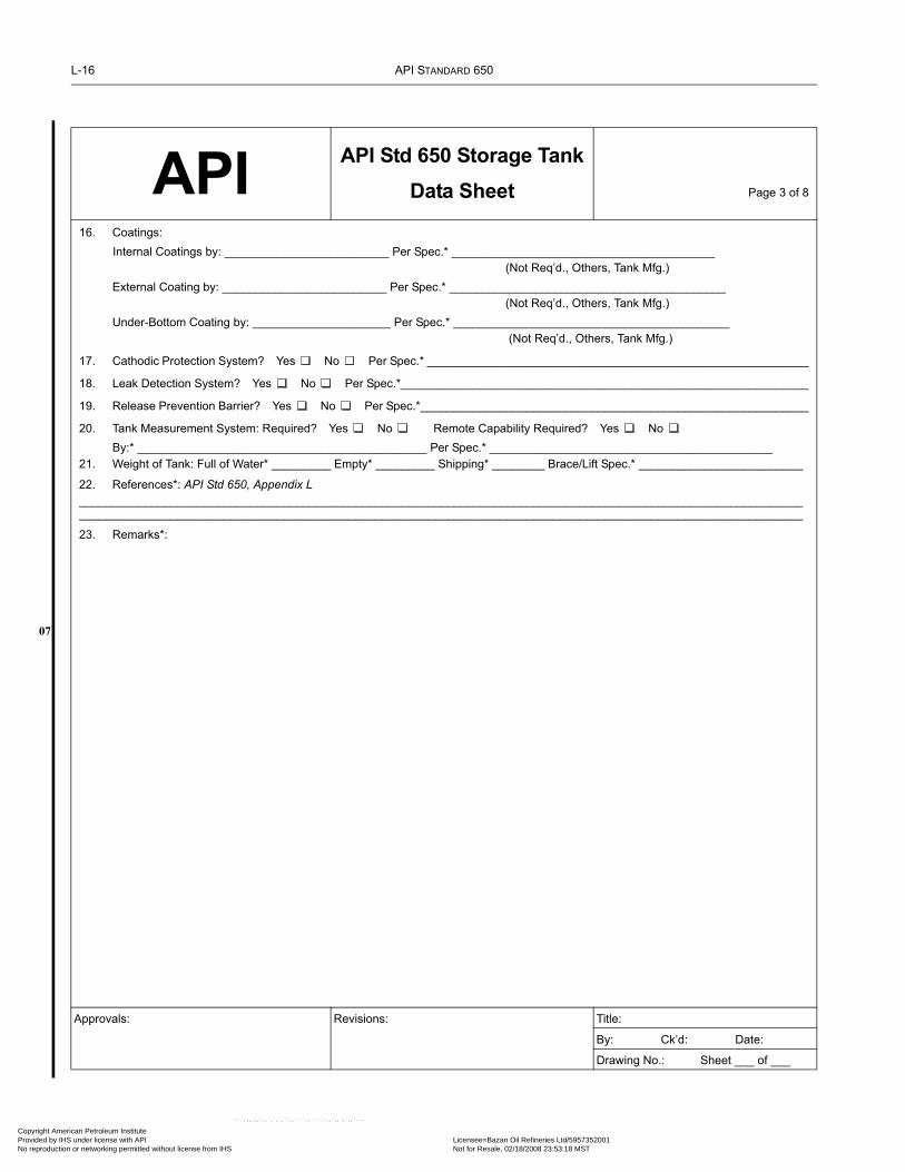
L-16 API STANDARD 650
07
Copyright AmProvided by No reproduc
API API Std 650 Storage TankData Sheet Page 3 of 8
16. Coatings:Internal Coatings by: _________________________ Per Spec.* ________________________________________
(Not Req’d., Others, Tank Mfg.)External Coating by: _________________________ Per Spec.* __________________________________________
(Not Req’d., Others, Tank Mfg.)Under-Bottom Coating by: _____________________ Per Spec.* __________________________________________
(Not Req’d., Others, Tank Mfg.)
17. Cathodic Protection System? Yes No Per Spec.* __________________________________________________________
18. Leak Detection System? Yes No Per Spec.*______________________________________________________________
19. Release Prevention Barrier? Yes No Per Spec.*___________________________________________________________
20. Tank Measurement System: Required? Yes No Remote Capability Required? Yes No By:* ____________________________________________ Per Spec.* ___________________________________________
21. Weight of Tank: Full of Water* _________ Empty* _________ Shipping* ________ Brace/Lift Spec.* _________________________
22. References*: API Std 650, Appendix L____________________________________________________________________________________________________________________________________________________________________________________________________________________________
23. Remarks*:
Approvals: Revisions: Title:
By: Ck’d: Date:
Drawing No.: Sheet ___ of ___
erican Petroleum Institute IHS under license with API Licensee=Bazan Oil Refineries Ltd/5957352001
Not for Resale, 02/18/2008 23:53:18 MSTtion or networking permitted without license from IHS
--``,,,,,,`,,`,`,`,``,,````,,``-`-`,,`,,`,`,,`---

WELDED STEEL TANKS FOR OIL STORAGE L-17
07
Copyright AmericaProvided by IHS uNo reproduction o
API API Std 650 Storage TankData Sheet
Page 4 of 8
* If box is blank, Manufacturer shall determine and submit as per Appendix L.Table 1 MATERIALS OF CONSTRUCTION
Component Material*/Thickness* C.A. Component Material* C.A.
Shell, Course __ to __ Reinforcing Pads
Shell, Course __ to __ Manhole/Nozzle Necks
Shell, Course __ to __ Manhole/Nozzle Flanges
Shell, Course __ to __ Flange Covers
Shell, Course __ to __ Anchor Attachments
Roof Submerged Piping
Bottom Wetted Structurals +
Annular Ring Non-wetted Structurals +
+ Check here if C.A. is to apply to each exposed surface .
Table 2 BOLTS and ANCHORS
Component Head Type* Bolt or Anchor Material* Nut Material* Thread Series* C.A.
Flange Bolting ++
Structural Bolting ++
Anchor Bolts ++
++ Total C.A., on the nominal diameter.
Table 3 NOZZLE and MANHOLE SCHEDULE* (for Fixed Roof, Shell, and Bottom)
Mark Service
Size, NPS, or Dia. (In.)
Neck Sch or Wall Thick.
Reinf. Plate Dimensions
Full Pen. On
Open. (Y/N)
Flange Type
Flange Class or Thick.
Gasket Bearing Surf. Dimen. and
FinishGasket Thick.
and Dimen.
Gasket Mat’l. and Descript.
Proj. to FF or CL or from
Datum Lines
Approvals: Revisions: Title:By: Ck’d: Date:
Drawing No.: Sheet ___ of ___
--``,,,,,,`,,`,`,`,``,,````,,``-`-`,,`,,`,`,,`---
n Petroleum Institute nder license with API Licensee=Bazan Oil Refineries Ltd/5957352001
Not for Resale, 02/18/2008 23:53:18 MSTr networking permitted without license from IHS

L-18 API STANDARD 650
07
Copyright AmProvided by No reproduc
API API Std 650 Storage TankData Sheet Page 5 of 8
* If box is blank, Manufacturer shall determine and submit as per Appendix L.OTHER TANK APPURTENANCES
24. Platform, Stairway, and Railing: Galvanizing Req’d?* Yes No Stairway Style* ____________Walk Surf. Type* __________
(Straight or Helical)
Stair and Walkway Clear Width* _________________ National Safety Standards*________________________________________
Architectural/Structural Specification* _________________________________________________________
Gauger’s Platform Req’d? Yes No Qty Req’d.* _____________ Per Spec. *___________________________________
25. Jacket Required?* Yes No Other Heaters/Coolers Required?* Yes No
Supplemental Jacket, Heater, or Cooler Specifications* ________________________________________________________
26. Mixer/Agitator: Quantity ________ Size* ________ Per Spec.* ___________________________________________
27. Insulation: Required? Yes No Thickness* ________ Material* __________________
Per Specs*_________________________________ Responsibility for Insulation and Installation ___________________________
(Purchaser, Manufacturer, Others)
28. Structural Attachments: Lift Lugs?* Yes No Desc.*_________________________________________________________
Shell Anchorage?* Yes No Type* ____________________________________Scaffold Cable Support? Yes No
29. Various Other Items: Welded Flush-Type: Shell Connection Cleanout Fitting Waive Application of Appendix P? Yes No
Miscellany #1 __________________________________ Miscellany #2 ______________________________________________
Miscellany #3 __________________________________ Miscellany #4 ______________________________________________
Miscellany #5 __________________________________ Miscellany #6 ______________________________________________
Table 4 OTHER TANK APPURTENANCES*
Mark QuantityService or
Description Size Orientation Height from Datum Material Remarks
Approvals: Revisions: Title:
By: Ck’d: Date:
Drawing No.: Sheet ___ of ___
erican Petroleum Institute
--``,,,,,,`,,`,`,`,``,,````,,``-`-`,,`,,`,`,,`---
IHS under license with API Licensee=Bazan Oil Refineries Ltd/5957352001 Not for Resale, 02/18/2008 23:53:18 MSTtion or networking permitted without license from IHS

WELDED STEEL TANKS FOR OIL STORAGE L-19
07
Copyright AmericaProvided by IHS uNo reproduction o
API API Std 650 Storage TankData Sheet Page 6 of 8
* If box is blank, Manufacturer shall determine and submit as per Appendix L.
FLOATING ROOF DATA30. Floating Roof Selection
Design Basis: Appendix C Or Appendix H
Type of Roof: (External or Internal): Single Deck Pontoon* Double Deck*
(Internal Only): Tubular Pontoon* Metallic Sandwich Panel*
Other ______________________________ Supplemental Spec.:_______________________
31. Seals
Primary Seal: Shoe Envelope Wiper/Compression Plate Other _______ Supplemental Spec: ________________
Shoe Mechanism: Mfg. Std. Other ________________________________________________
Electrically Isolate Mechanism from Shoes? Yes No Wax Scrapers Required? Yes No
Minimum Shoe Thickness* ____________ Carbon Steel Shoes to be Galvanized? Yes No
Secondary Seal: Shoe Envelope Wiper None Other _________________ Supplemental Spec: ______________
32. Data for All Floating Roofs:
Overflow Openings in Shell Acceptable? Yes No Shell Extension? Yes No
Roof-Drain Check Valves Required? Yes No Roof-Drain Isolation Valves Required? Yes No
Freeze Protection for Roof Drains Required? No Yes Supplemental Requirements: ____________________
Roof-Drain Piping to External Nozzles: Mfg. Std. Armored Flexible Pipe Swivels in Rigid Pipe Other ___________________
Foam Dam? Yes No Supplemental Spec. __________________________________
Minimum Deck Thickness* ___________________________
Bulkhead Top Edges to be Liquid-Tight? Yes No Seal-weld Underside of Roof? Yes No
Electrical Bonding: Shunts: Yes No Cables: Yes No Supplemental Spec. __________________________________
Qty of Non-Guide-Pole Gauge Wells Required __________ Qty of Sample Hatches Required ___________
Guide Pole for Gauging? Yes No Slots in Guide Pole? Yes No Datum Plates? Yes No Striking Plates? Yes No
Guide Pole Emissions-Limiting Devices: Sliding Cover Pole Wiper Pole Sleeve Float Float Wiper Pole Cap
Qty. of Roof Manholes* _______ Minimum High-Roof Clearance Above Bottom: _______
Removable Leg Storage Racks? Yes No ; Leg Sleeves or Fixed Low Legs
33. Additional Data for External Floating Roofs:
Weather Shield? Yes No Suppl. Spec. ____________________
Rolling Ladder Req’d? Yes No Field Adjustable Legs? Yes No
Design Rainfall Intensity ________In./Hr. (mm/hr) Based on a ________ Minute Duration Associated with the ____________ Storm
Design Accumulated 24-Hour Rainfall ________In. (mm) Based on the ____________ Storm
Distortion and Stability Determinations Required? Yes No Supplemental Specification __________________________________
Landed Live Load* ______ Approvals: Revisions: Title:
By: Ck’d: Date:Drawing No.: Sheet ___ of ___
--``,,,,,,`,,`,`,`,``,,````,,``-`-`,,`,,`,`,,`---
n Petroleum Institute nder license with API Licensee=Bazan Oil Refineries Ltd/5957352001
Not for Resale, 02/18/2008 23:53:18 MSTr networking permitted without license from IHS

L-20 API STANDARD 650
07
Copyright AmProvided by No reproduc
API API Std 650 Storage TankData Sheet Page 7 of 8
34. Additional Data for Internal Floating Roofs:
Two-Position Legs? Yes No Cable-Supported Roof? Yes No Fixed-Roof Inspection Hatches Required?: Yes No
Internal Roof Drain Required? Yes No Omit Distribution Pads Supporting Uniform Live Loads? Yes No
Corrosion Gauge Required? Yes No Fixed Ladder Required?: Yes No ; Type of Roof Vent: *_____________
Modified Minimum Point Load? Yes No Supplemental Specification __________________________________
Mfr. to Leak Test * ___ % of Compartments in Assembly Yard in Erected Position Unknown; see separate contract terms
Roof Erector's Flotation Test: w/ tank hydro at completion of roof at later date ______ Not required
Flotation Test Media: Water Product (see H.6.6.1) Water Quality: Potable Other See Supplemental Spec _____________
Flotation Test: Duration _______ Fill Height: ______
Flotation Test Items provided by Purchaser (see H.6.7): None List Attached
Responsible Party for Inspecting Roof during Initial Fill: Purchaser Other __________________
Table 5 FLOATING ROOF MATERIALSComponent Material*/Thickness* C.A./Coating* Component Material*/Thickness* C.A./Coating*
Deck Plate Datum Plate
Inner Rim Plate Tubular Pontoon
Outer Rim Plate Pontoon Bulkhead
Foam Dam Submerged Pipe
Sandwich Panel Face Plate Guide Pole
Sandwich Panel Core Secondary Seal
Gauge Well Secondary Seal Fabric
Drain Sumps Wiper Tip
Opening Sleeves Wax Scraper
Floating Suction Lines Weather Seal
Primary Fabric Seal Envelope Fabric
Foam Log Core Shoe Mechanisms
Landing Legs Primary Seal Shoe
Landing Leg Bottom Pads Removable Covers
Manhole Necks Rolling Ladder
Vents Inlet Diffusers
Approvals: Revisions: Title:
By: Ck’d: Date:Drawing No.: Sheet ___ of ___
erican Petroleum Institute IHS under license with API Licensee=Bazan Oil Refineries Ltd/5957352001
Not for Resale, 02/18/2008 23:53:18 MSTtion or networking permitted without license from IHS
--``,,,,,,`,,`,`,`,``,,````,,``-`-`,,`,,`,`,,`---

WELDED STEEL TANKS FOR OIL STORAGE L-21
07
Copyright AmericaProvided by IHS uNo reproduction o
API API Std 650 Storage TankData Sheet Page 8 of 8
* If box is blank, Manufacturer shall determine and submit as per Appendix L.
Tank Plan and Sketches:
Notes:
Approvals: Revisions: Title:By: Ck’d: Date:Drawing No.: Sheet ___ of ___
--``,,,,,,`,,`,`,`,``,,````,,``-`-`,,`,,`,`,,`---
n Petroleum Institute nder license with API Licensee=Bazan Oil Refineries Ltd/5957352001
Not for Resale, 02/18/2008 23:53:18 MSTr networking permitted without license from IHS

L-22 API STANDARD 650
07
Copyright AmProvided by No reproduc
--``,,,,,,`,,`,`,`,``,,````,,``-`-`,,`,,`,`,,`---
Table L-1—Index of Decisions or Actions Which may be Required of the Tank Purchaser
Foreword 1.1.21.1.31.1.51.1.61.1.11Table 1-1 (App. C, E, G, I, L, O, P, V, W)1.1.151.1.181.1.221.1.281.3.21.3.31.44.1.1.44.1.24.1.34.1.5 (b)4.2.1.34.2.5Table 4-1 (Note 1)Table 4-2 (Note C)4.2.7.44.2.8.14.2.9.24.2.10.44.4.1 (g)4.4.24.6.24.74.9.1.14.9.1.44.9.1.54.9.24.9.3.15.1.3.6.15.1.3.85.1.5.3 (b)5.1.5.45.1.5.55.1.5.8 (b)5.1.5.9 (e)5.2.1 (a, b, f, g, h, j, 1)5.2.25.2.3 (a, b, c)5.2.45.2.6.15.3.1.15.3.2.15.3.2.35.3.2.65.3.35.3.45.4.15.4.45.4.5
5.6.1.1 (Notes 1, 3)5.6.1.2Table 5-2 (Note a)5.6.3.2 (H, G, CA)5.6.4.15.6.4.6 (H)5.7.1.45.7.1.8Figure 5-6 (Note 5)Figure 5-7A (Notes 1, 7)Figure 5-7B (Note 6)Figure 5-8 (Note 4)5.7.2.25.7.2.3 (b)Table 5-6 (Note c)Table 5-8 (Note d)Table 5-9 (Note c)Figure 5-12 (Note 4)5.7.3.45.7.4.55.7.5.25.7.6.1.a5.7.6.1.b5.7.6.25.7.6.35.7.7.15.7.8.15.8.25.8.5.35.8.5.45.8.75.8.10 (c)5.8.11.25.8.11.35.9.3.35.9.6.1 (Note)5.9.7.1 (t, d)5.9.7.2 (tuniform, tactual)5.9.7.75.10.2.25.10.2.45.10.2.65.10.2.75.10.2.85.10.3.15.10.3.45.10.4.15.10.4.45.10.4.55.10.55.10.65.12.55.12.65.12.106.1.1.16.1.2 (Note)
6.1.36.2.16.2.36.2.47.1.17.1.47.2.1.17.2.1.77.2.3.37.2.4.17.2.4.37.3.1.37.3.2.17.3.2.37.3.5, 17.3.6.2 (2, 3, 4, 5, 7)7.3.6.37.3.6.5 (Note)7.3.7.27.4.1 7.4.47.5.18.1.2.78.1.48.1.68.1.7.28.1.8.28.3.2.58.6.38.6.108.6.119.2.1.110.1.1 (e, f, g, j, k)Figure 10-1 (Note)10.3 (Note)A.1.1A.1.2A.3.4A.4.1 (G, CA)A.6A.8.2A.9.2B.3.3B.3.4B.4.4.1C.1C.3.1.1C.3.1.2C.3.1.5C.3.3.2C.3.4.1 (b)C.3.4.2C.3.5C.3.7C.3.8.1 (1, 3)C.3.8.2
erican Petroleum Institute IHS under license with API Licensee=Bazan Oil Refineries Ltd/5957352001
Not for Resale, 02/18/2008 23:53:18 MSTtion or networking permitted without license from IHS

WELDED STEEL TANKS FOR OIL STORAGE L-23
07
Copyright AmericaProvided by IHS uNo reproduction o
C.3.8.3C.3.10.1C.3.10.3 (b)C.3.10.4C.3.10.8C.3.10.9C.3.12.3C.3.13.2C.3.13.5 (Primary, Secondary Seal)C.3.14.1 (1)C.3.14.2C.3.14.4C.3.14.5C.3.14.6C.3.15.2C.3.15.3C.3.15.4 (a, e)E.1E.3.1E.4.1E.4.2E.4.2.4E.4.4E.4.6.1E.4.6.2E.5.1.2E.6.1.3E.6.1.5E.6.1.6E.6.2.1.2E.7.2E.7.5F.5.1F.7.4G.1.3.2G.1.3.3G.1.4.1G.1.4.2G.1.4.4G.2.1G.2.4G.4.3G.5.3G.6.2G.7G.8.3G.9G.10.1.1G.10.1.2G.11.3H.1.1H.1.2
H.1.3H.2.2 (f, g, h)H.3H.4.1.6H.4.1.7H.4.1.8H.4.1.9H.4.1.10H.4.2.1.1H.4.2.1.3H.4.2.2H.4.2.3.2H.4.3.3H.4.3.3.1H.4.3.4H.4.3.5H.4.4H.4.4.2H.4.4.4H.4.6.1H.4.6.2H.4.6.3H.4.6.5H.4.6.6H.4.6.7H.4.6.8H.4.6.9H.5.1.1H.5.1.4H.5.2.1H.5.2.2.1H.5.2.2.3H.5.3.1H.5.3.2H.5.3.3H.5.5.3H.5.6H.5.7H.5.8H.5.9H.6.1H.6.2H.6.4 (Note)H.6.6H.6.6.1I.1.2I.1.3I.2 (c)I.5.5I.6.2I.6.3I.6.4
I.7.1I.7.3.2 (CA) I.7.6J.1.2J.3.6.2J.3.7.1J.3.7.2J.3.8.2J.4.2.2Appendix LM.1.2 (Note)M.2M.4.2 (C)N.2.1N.2.2N.2.4N.2.5N.2.6O.2.2O.2.6O.3.1.4P.1P.2.1P.2.2P.2.8.1P.2.8.2R.2S.1.2Table S-1a (Notes 1, 2, 3, 5)Table S-1b (Notes 1, 2, 3, 5)S.2.1.2S.2.2S.3.1S.3.2 (G, CA)S.4.3.2S.4.4.3S.4.5.1Table S-2 (Notes 2, 3)Table S-3 (Note 4)S.4.9.2S.4.10.2 (a, f)S.4.10.3S.4.13S.6 (a)U.3.1U.3.3U.3.5U.4.3Appendix VAppendix W
--``,,,,,,`,,`,`,`,``,,````,,``-`-`,,`,,`,`,,`---
n Petroleum Institute nder license with API Licensee=Bazan Oil Refineries Ltd/5957352001
Not for Resale, 02/18/2008 23:53:18 MSTr networking permitted without license from IHS

Copyright AmProvided by No reproduc
erican Petroleum Institute IHS under license with API Licensee=Bazan Oil Refineries Ltd/5957352001
Not for Resale, 02/18/2008 23:53:18 MSTtion or networking permitted without license from IHS
--``,,,,,,`,,`,`,`,``,,````,,``-`-`,,`,,`,`,,`---

07
•
07
•
07
Copyright AmericaProvided by IHS uNo reproduction o
--``,,,,,,`,,`,`,`,``,,````,,``-`-`,,`,,`,`,,`---
APPENDIX M—REQUIREMENTS FOR TANKS OPERATING AT ELEVATED TEMPERATURES
M.1 ScopeM.1.1 This appendix specifies additional requirements for API Std 650 tanks with a maximum design temperature exceeding93°C (200°F) but not exceeding 260°C (500°F).
M.1.2 The following shall not be used for a maximum design temperature above 93°C (200°F):
a. Open-top tanks (see 5.9).b. Floating-roof tanks (see Appendix C).c. Structurally-supported aluminum dome roofs (see G.1.1 and note below).d. Internal floating roofs constructed of aluminum (see H.2.2 and note below).e. Internal floating roofs constructed of composite material (see H.2.2). Lower temperature limits may apply for this roof mate-rial type.
Note: An exception may be made by the Purchaser for Item e, if the following criteria is met:
a. Allowable stress reductions for aluminum alloys are determined in accordance with ANSI/ASME B96.1 Welded Aluminum Alloy StorageTanks, and alloys are evaluated for the potential of exfoliation.b. Gaskets and seals are evaluated for suitability at the maximum design temperature.
M.1.3 Internal floating roofs in accordance with Appendix H may be used for a maximum design temperature above 93°C(200°F), subject to the applicable requirements of this appendix. The vapor pressure of the liquid must be considered. Sealingdevices, particularly those of fabric and nonmetallic materials, shall be suitable for the maximum design temperature.
M.1.4 Tanks for small internal pressures in accordance with Appendix F may be used for a maximum design temperature above93°C (200°F), subject to the requirements of M.3.6, M.3.7, and M.3.8.
M.1.5 Shop-assembled tanks in accordance with Appendix J may be used for a maximum design temperature above 93°C(200°F), subject to the applicable requirements of this appendix.
M.1.6 The nameplate of the tank shall indicate that the tank is in accordance with this appendix by the addition of M to theinformation required by 10.1.1. In addition, the nameplate shall be marked with the maximum design temperature in the spaceindicated in Figure 10-1.
M.2 Thermal EffectsThis appendix does not provide detailed rules for limiting loadings and strains resulting from thermal effects, such as differentialthermal expansion and thermal cycling, that may exist in some tanks operating at elevated temperatures. Where significant ther-mal effects will be present, it is the intent of this appendix that the Purchaser define such effects. The Manufacturer shall propose,subject to the Purchaser’s acceptance, details that will provide strength and utility equivalent to those provided by the details spec-ified by this Standard in the absence of such effects.For a maximum design temperature above 93°C (200°F), particular consideration should be given to the following thermaleffects:
a. Temperature differences between the tank bottom and the lower portion of the shell. Such thermal differences may result fromfactors such as the method and sequence of filling and heating or cooling, the degree of internal circulation, and heat losses to thefoundation and from the shell to the atmosphere. With such temperature differences, it may be necessary to provide for increasedpiping flexibility, an improved bottom-to-shell joint, and a thicker annular ring or bottom sketch plates to compensate forincreased rotation of the bottom-to-shell joint (see M.4.2).b. The ability of the bottom to expand thermally, which may be limited by the method of filling and heating. With such a condi-tion, it may be necessary to provide improved bottom welding in addition to the details suggested in Item a.c. Temperature differences or gradients between members, such as the shell and the roof or stairways, the shell and stiffeners, theroof or shell and the roof supports, and locations with insulation discontinuities.
M-1
n Petroleum Institute nder license with API Licensee=Bazan Oil Refineries Ltd/5957352001
Not for Resale, 02/18/2008 23:53:18 MSTr networking permitted without license from IHS

M-2 API STANDARD 650
07
Copyright AmProvided by No reproduc
d. Whether or not the contents are allowed to solidify and are later reheated to a liquid, including the effect on columns, beams,and rafters. The possible build-up of solids on these components and the potential for plugging of the vent system should also beconsidered.e. The number and magnitude of temperature cycles the tank is expected to undergo during its design life.
M.3 Modifications in Stress and ThicknessM.3.1 For a maximum design temperature not exceeding 93°C (200°F), the allowable stress specified in 5.6.2 (see Table 5-2)for calculating shell thickness need not be modified.
M.3.2 For a maximum design temperature exceeding 93°C (200°F), the allowable stress specified in 5.6.2 shall be modified asfollows: The allowable stress shall be two-thirds the minimum specified yield strength of the material multiplied by the applicablereduction factor given in Table M-1 or the value given in Table 5-2 for product design stress, whichever is less.
M.3.3 The allowable stress of 145 MPa (21,000 lbf/in2) in the equation for shell-plate thickness in A.4.1 shall be multiplied bythe applicable reduction factor given in Table M-1.
M.3.4 The requirements of 5.7.5 for shell manholes, 5.7.7 for flush-type cleanout fittings and of 5.7.8 for flush-type shell con-nections shall be modified. The thickness of bottom reinforcing plate for flush-type shell cleanouts and flush-type shell connec-tions and bolting flange and cover plates for shell manhole and flush-type shell cleanouts shall be multiplied by the ratio of205 MPa (30,000 lbf/in.2) to the material yield strength at the maximum design temperature if the ratio is greater than one.
M.3.5 The structural allowable stresses specified in 5.10.3, including the allowable stresses dependent on the modulus of elas-ticity, shall be multiplied by the yield strength reduction factors from Table M-1 at the maximum design temperature.
M.3.6 In the two equations in F.4.1 and F.5, the value 1.1 (or 30,800) shall be multiplied by the ratio of the material’s yieldstrength at the maximum design temperature to 205 MPa (30,000 lbf/in.2) if the ratio is less than 1.0 (see Table M-1 for yieldstrength reduction factors).
M.3.7 The allowable stress specified in F.7.2 shall be multiplied by the ratio of the material’s yield strength at the maximumdesign temperature to 188 MPa (or 27,300 lbf/in.2) if the ratio is less than 1.0 (see Table M-1 for yield strength reduction factors).
M.3.8 If the anchors are insulated, the allowable stresses specified in Tables 5-21 and 5-22 shall be multiplied by the ratio ofthe material’s yield strength at the maximum design temperature to 205 MPa (30,000 lbf/in.2) if the ratio is less than 1.0 (seeTable M-1 for yield strength reduction factors).
M.4 Tank BottomsM.4.1 Tanks with diameters exceeding 30 m (100 ft) shall have butt-welded annular bottom plates (see 5.1.5.6).
M.4.2 The following simplified procedure is offered as a recommended design practice for elevated-temperature tanks wheresignificant temperature differences between the tank bottom and the lowest shell course are expected. The use of the procedure isnot intended to be mandatory. It is recognized that other analytical procedures can be employed as well as that operating condi-tions may preclude the need for such a procedure.
Table M-1—Yield Strength Reduction Factors
Minimum Specified Yield Strength (MPa [lbf/in.2])
Temperature < 310 MPa(< 45,000 lbf/in.2)
From ≥ 310 to < 380 MPa(≥ 45,000 to < 55,000 lbf/in.2)
≥ 380 MPa(≥ 55,000 lbf/in.2)(°C) (°F)
94 201 0.91 0.88 0.92
150 300 0.88 0.81 0.87
200 400 0.85 0.75 0.83
260 500 0.80 0.70 0.79
Note: Linear interpolation shall be applied for intermediate values.
erican Petroleum Institute IHS under license with API Licensee=Bazan Oil Refineries Ltd/5957352001
Not for Resale, 02/18/2008 23:53:18 MSTtion or networking permitted without license from IHS
--``,,,,,,`,,`,`,`,``,,````,,``-`-`,,`,,`,`,,`---

WELDED STEEL TANKS FOR OIL STORAGE M-3
07
Copyright AmericaProvided by IHS uNo reproduction o
--``,,,,,,`,,`,`,`,``,,````,,``-`-`,,`,,`,`,,`---
Shell-to-bottom junctions in elevated-temperature tanks may be evaluated for liquid head and temperature cycles with the for-mulas, procedures, and exclusions given below. (See Conditions a and b in the note below, which exclude tanks from suchanalyses.)
Note: A cyclic design life evaluation need not be made if all the criteria of either of the following conditions are met:
a. The design temperature difference (T) is less than or equal to 220°C (400°F), K is less than or equal to 2.0, and C is less than or equal to 0.5.b. A heated liquid head, in feet, greater than or equal to 0.3(Dt)0.5 is normally maintained in the tank, except for an occasional cool-down(about once a year) to ambient temperatures; T is less than or equal to 260°C (500°F); and K is less than or equal to 4.0. (For background infor-mation on the development of the stress formulas, design life criteria, and C and B factors, see G.G. Karcher, “Stresses at the Shell-to-BottomJunction of Elevated-Temperature Tanks.”)
In SI units:
(If N is greater than or equal to 1300, cycling at the shell-to-bottom junction is not a controlling factor.)
where
N = number of design liquid level and temperature cycles estimated for the tank design life (usually less than 1300).This design procedure contains a conservative safety margin. It is not necessary to monitor actual in-service temper-ature and liquid head cycles
K = stress concentration factor for the bottom plate at the toe of the inside shell-to-bottom fillet weld
= 4.0 for shell-to-bottom fillet welds and lap-welded bottom plates
= 2.0 for butt-welded annular plates where the shell-to-bottom fillet welds have been inspected by 100% magneticparticle examination (see 8.2). This magnetic particle examination shall be performed on the root pass at every13 mm of deposited weld metal while the weld is being made and on the completed weld. The examination shall beperformed before hydrostatic testing
= one-half the maximum stress range that occurs in the annular plate at the shell-to-bottom junction weld, in MPa.The H and CT terms must be large enough to cause a positive S. A negative S indicates that loading conditions arenot sufficient to satisfy the development assumptions of this formula. Specifically stated, the following inequalitymust be satisfied when the equation for S is used:
When the equation for S is used, the shell thickness t must be greater than or equal to the annular-plate thickness tb
T = difference between the minimum ambient temperature and the maximum design temperature (°C)
Sy = specified minimum yield strength of the bottom plate at the maximum design temperature (MPa)
D = nominal tank diameter (m)
H = difference in filling height between the full level and the low level (m)
G = design specific gravity of the liquid
t = nominal thickness of the tank’s bottom shell course (mm)
tb = nominal thickness of the annular bottom plate (mm)
N 9.7 103×KS
---------------------⎝ ⎠⎛ ⎞
2.44
=
S0.028D2tb
0.25
t---------------------------- 58HG
Dt( )0.5--------------- 26.2CTt0.5
D1.5-------------------------4.8BSytb
2
Dt( )1.5--------------------– G–+
×=
58HGDt( )0.5--------------- 26.2CTt0.5
D1.5------------------------- G–+
4.8BSytb2
Dt( )1.5-------------------->
n Petroleum Institute nder license with API Licensee=Bazan Oil Refineries Ltd/5957352001
Not for Resale, 02/18/2008 23:53:18 MSTr networking permitted without license from IHS

M-4 API STANDARD 650
•
07
Copyright AmProvided by No reproduc
C = factor to account for radial restraint of the tank’s shell-to-bottom junction with respect to free thermal expansion(Cmax = 1.0; Cmin = 0.25). The actual design value of C shall be established considering the tank’s operating andwarm-up procedure and heat transfer to the subgrade26
= 0.85 if no C factor is specified by the Purchaser
B = foundation factor26
= 2.0 for tanks on earth foundations
= 4.0 for tanks on earth foundations with a concrete ringwall
In US Customary units:
(If N is greater than or equal to 1300, cycling at the shell-to-bottom junction is not a controlling factor.)
where
N = number of design liquid level and temperature cycles estimated for the tank design life (usually less than 1300).This design procedure contains a conservative safety margin. It is not necessary to monitor actual in-service temper-ature and liquid head cycles
K = stress concentration factor for the bottom plate at the toe of the inside shell-to-bottom fillet weld
= 4.0 for shell-to-bottom fillet welds and lap-welded bottom plates
= 2.0 for butt-welded annular plates where the shell-to-bottom fillet welds have been inspected by 100% magnetic parti-cle examination (see 8.2). This magnetic particle examination shall be performed on the root pass at every 1/2 in. ofdeposited weld metal while the weld is being made and on the completed weld. The examination shall be performedbefore hydrostatic testing
= one-half the maximum stress range that occurs in the annular plate at the shell-to-bottom junction weld, in poundsper square inch. The H and CT terms must be large enough to cause a positive S. A negative S indicates that loadingconditions are not sufficient to satisfy the development assumptions of this formula. Specifically stated, the follow-ing inequality must be satisfied when the equation for S is used:
When the equation for S is used, the shell thickness t must be greater than or equal to the annular-plate thickness tb
T = difference between the minimum ambient temperature and the maximum design temperature (°F)
Sy = specified minimum yield strength of the bottom plate at the maximum design temperature (lbf/in.2)
D = nominal tank diameter (ft)
H = difference in filling height between the full level and the low level (ft)
26G. G. Karcher, “Stresses at the Shell-to-Bottom Junction of Elevated-Temperature Tanks,” 1981 Proceedings—Refining Department,Volume 60, American Petroleum Institute, Washington D.C. 1981, pp. 154 – 159.
N 1.4 106×KS
---------------------⎝ ⎠⎛ ⎞
2.44
=
S0.033D2tb
0.25
t---------------------------- 6.3HG
Dt( )0.5---------------- 436CTt0.5
D1.5-----------------------BSy tb
2
Dt( )1.5---------------– G–+
×=
6.3HGDt( )0.5---------------- 436CTt0.5
D1.5----------------------- G–+ BSy tb2
Dt( )1.5--------------->
--``,,,,,,`,,`,`,`,``,,````,,``-`-`,,`,,`,`,,`---
erican Petroleum Institute IHS under license with API Licensee=Bazan Oil Refineries Ltd/5957352001
Not for Resale, 02/18/2008 23:53:18 MSTtion or networking permitted without license from IHS

WELDED STEEL TANKS FOR OIL STORAGE M-5
Copyright AmericaProvided by IHS uNo reproduction o
G = design specific gravity of the liquid
t = nominal thickness of the tank’s bottom shell course (in.)
tb = nominal thickness of the annular bottom plate (in.)
C = factor to account for radial restraint of the tank’s shell-to-bottom junction with respect to free thermal expansion(Cmax = 1.0; Cmin = 0.25). The actual design value of C shall be established considering the tank’s operating andwarm-up procedure and heat transfer to the subgrade26
= 0.85 if no C factor is specified by the Purchaser
B = foundation factor26
= 2.0 for tanks on earth foundations
= 4.0 for tanks on earth foundations with a concrete ringwall
M.5 Self-Supporting RoofsM.5.1 The requirements of 5.10.5 and 5.10.6, which are applicable to self-supporting roofs, shall be modified. For a maxi-mum design temperature above 93°C (200°F), the calculated minimum thickness of roof plates, as defined in 5.10.5 and 5.10.6,shall be increased by the ratio of 199,000 MPa (28,800,000 lbf/in.2) to the material’s modulus of elasticity at the maximumdesign temperature.
M.5.2 Table M-2 shall be used to determine the material’s modulus of elasticity at the maximum operating temperature.
M.6 Wind GirdersIn the equation for the maximum height of unstiffened shell in 3.9.7.1, the maximum height (H1) shall be reduced by the ratio ofthe material’s modulus of elasticity at the maximum design temperature to 199,000 MPa (28,800,000 lbf/in.2) when the ratio isless than 1.0 (see Table M-2 for modulus of elasticity values).
Table M-2—Modulus of Elasticity at the Maximum Design Temperature
Maximum Design Temperature Modulus of Elasticity
°C °F MPa lbf/in.2
93 200 199,000 28,800,000
150 300 195,000 28,300,000
200 400 191,000 27,700,000
260 500 188,000 27,300,000
Note: Linear interpolation shall be applied for intermediate values.
n Petroleum Institute nder license with API Licensee=Bazan Oil Refineries Ltd/5957352001
Not for Resale, 02/18/2008 23:53:18 MSTr networking permitted without license from IHS
--``,,,,,,`,,`,`,`,``,,````,,``-`-`,,`,,`,`,,`---

Copyright AmProvided by No reproduc
erican Petroleum Institute IHS under license with API Licensee=Bazan Oil Refineries Ltd/5957352001
Not for Resale, 02/18/2008 23:53:18 MSTtion or networking permitted without license from IHS
--``,,,,,,`,,`,`,`,``,,````,,``-`-`,,`,,`,`,,`---

•
•
•
•
•
Copyright AmericaProvided by IHS uNo reproduction o
APPENDIX N—USE OF NEW MATERIALS THAT ARE NOT IDENTIFIED
N.1 GeneralNew or unused plates and seamless or welded pipe that are not completely identified as complying with any listed specificationmay be used in the construction of tanks covered by this Standard, under the conditions specified in N.2.
N.2 ConditionsN.2.1 A material may be used if an authentic test record for each heat or heat-treating lot of material is available that proves thatthe material has chemical requirements and mechanical properties within the permissible range of a specification listed in thisStandard. If the test requirements of the listed specification are more restrictive than any specification or authentic tests that havebeen reported for the material, more restrictive tests shall be performed in accordance with the requirements of the listed specifi-cation, and the results shall be submitted to the Purchaser for approval.
N.2.2 If an authentic test record is not available or if all the material cannot be positively identified with the test record by legi-ble stamping or marking, the following requirements apply:
a. Each plate shall be subjected to the chemical analysis and physical tests required by the designated specification, with the fol-lowing modifications: The carbon and manganese contents shall be determined in all check analyses. When the designatedspecification does not specify carbon and manganese limits, the Purchaser shall decide whether these contents are acceptable.When the direction of rolling is not definitely known, two tension specimens shall be taken at right angles to each other from acorner of each plate, and one tension specimen shall meet the specification requirements.b. Each length of pipe shall be subjected to a chemical check analysis and sufficient physical tests to satisfy the Purchaser that allof the material is properly identified with a given heat or heat-treatment lot and that the chemical and physical requirements of thedesignated specification are met. Material specified as suitable for welding, cold bending, close coiling, and the like shall be givensufficient check tests to satisfy the Purchaser that each length of material is suitable for the fabrication procedure to be used.
N.2.3 Charpy V-notch impact tests must be performed when required by Figure 4-1 to verify that the material possesses thetoughness required by Table 4-4.
N.2.4 After a material is properly identified with a designated specification and the Purchaser is satisfied that the material com-plies with the specification in all respects, the testing agency shall stencil or otherwise mark, as permitted by the specification, aserial S number on each plate or each length of pipe (or as alternatively provided for small sizes in the specification) in the pres-ence of the Purchaser.
N.2.5 Suitable report forms clearly marked “Report on Tests of Nonidentified Materials” shall be furnished by the tank Manu-facturer or testing agency. The forms shall be properly filled out, certified by the testing agency, and approved by the Purchaser.
N.2.6 The Purchaser shall have the right to accept or reject the testing agency or the test results.
N.2.7 The requirements for fabrication applicable to the designated specification to which the nonidentified material corre-sponds shall be followed, and the allowable design stress values shall be those specified in this Standard for the correspondingspecification.
--``,,,,,,`,,`,`,`,``,,````,,``-`-`,,`,,`,`,,`---
N-1
n Petroleum Institute nder license with API Licensee=Bazan Oil Refineries Ltd/5957352001
Not for Resale, 02/18/2008 23:53:18 MSTr networking permitted without license from IHS

Copyright AmProvided by No reproduc
erican Petroleum Institute IHS under license with API Licensee=Bazan Oil Refineries Ltd/5957352001
Not for Resale, 02/18/2008 23:53:18 MSTtion or networking permitted without license from IHS
--``,,,,,,`,,`,`,`,``,,````,,``-`-`,,`,,`,`,,`---
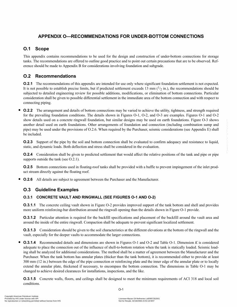
•
•
•
Copyright AmericaProvided by IHS uNo reproduction o
--``,,,,,,`,,`,`,`,``,,````,,``-`-`,,`,,`,`,,`---
APPENDIX O—RECOMMENDATIONS FOR UNDER-BOTTOM CONNECTIONS
O.1 ScopeThis appendix contains recommendations to be used for the design and construction of under-bottom connections for storagetanks. The recommendations are offered to outline good practice and to point out certain precautions that are to be observed. Ref-erence should be made to Appendix B for considerations involving foundation and subgrade.
O.2 RecommendationsO.2.1 The recommendations of this appendix are intended for use only where significant foundation settlement is not expected.It is not possible to establish precise limits, but if predicted settlement exceeds 13 mm (1/2 in.), the recommendations should besubjected to detailed engineering review for possible additions, modifications, or elimination of bottom connections. Particularconsideration shall be given to possible differential settlement in the immediate area of the bottom connection and with respect toconnecting piping.
O.2.2 The arrangement and details of bottom connections may be varied to achieve the utility, tightness, and strength requiredfor the prevailing foundation conditions. The details shown in Figures O-1, O-2, and O-3 are examples. Figures O-1 and O-2show details used on a concrete ringwall foundation, but similar designs may be used on earth foundations. Figure O-3 showsanother detail used on earth foundations. Other arrangements of foundation and connection (including combination sump andpipe) may be used under the provisions of O.2.6. When required by the Purchaser, seismic considerations (see Appendix E) shallbe included.
O.2.3 Support of the pipe by the soil and bottom connection shall be evaluated to confirm adequacy and resistance to liquid,static, and dynamic loads. Both deflection and stress shall be considered in the evaluation.
O.2.4 Consideration shall be given to predicted settlement that would affect the relative positions of the tank and pipe or pipesupports outside the tank (see O.2.1).
O.2.5 Bottom connections used in floating-roof tanks shall be provided with a baffle to prevent impingement of the inlet prod-uct stream directly against the floating roof.
O.2.6 All details are subject to agreement between the Purchaser and the Manufacturer.
O.3 Guideline ExamplesO.3.1 CONCRETE VAULT AND RINGWALL (SEE FIGURES O-1 AND O-2)
O.3.1.1 The concrete ceiling vault shown in Figure O-2 provides improved support of the tank bottom and shell and providesmore uniform reinforcing-bar distribution around the ringwall opening than the details shown in Figure O-1 provide.
O.3.1.2 Particular attention is required for the backfill specifications and placement of the backfill around the vault area andaround the inside of the entire ringwall. Compaction shall be adequate to prevent significant localized settlement.
O.3.1.3 Consideration should be given to the soil characteristics at the different elevations at the bottom of the ringwall and thevault, especially for the deeper vaults to accommodate the larger connections.
O.3.1.4 Recommended details and dimensions are shown in Figures O-1 and O-2 and Table O-1. Dimension K is consideredadequate to place the connection out of the influence of shell-to-bottom rotation when the tank is statically loaded. Seismic load-ing shall be analyzed for additional considerations. The method shall be a matter of agreement between the Manufacturer and thePurchaser. When the tank bottom has annular plates (thicker than the tank bottom), it is recommended either to provide at least300 mm (12 in.) between the edge of the pipe connection or reinforcing plate and the inner edge of the annular plate or to locallyextend the annular plate, thickened if necessary, to encompass the bottom connection. The dimensions in Table O-1 may bechanged to achieve desired clearances for installations, inspections, and the like.
O.3.1.5 Concrete walls, floors, and ceilings shall be designed to meet the minimum requirements of ACI 318 and local soilconditions.
O-1
n Petroleum Institute nder license with API Licensee=Bazan Oil Refineries Ltd/5957352001
Not for Resale, 02/18/2008 23:53:18 MSTr networking permitted without license from IHS

O-2 API STANDARD 650
Copyright AmProvided by No reproduc
O.3.2 EARTH FOUNDATION (SEE FIGURE O-3)
O.3.2.1 The detail shown in Figure O-3 provides an alternative arrangement for tanks where a concrete ringwall is notprovided.
O.3.2.2 Soil and backfill support capability shall be evaluated to ensure that reasonably uniform settlement (if any) will occurunder the loads imposed.
O.3.2.3 When the pipe is connected to the bottom at an angle, consideration should be given to design for unbalanced forces ifthe pipe is trimmed flush with the bottom.
O.3.2.4 When seismically-induced loadings are specified, such loadings under the tank bottom and shell shall be consideredwhen the depth and type of backfill around and over the pipe are selected.
Table O-1—Dimensions of Under-Bottom Connections
Inlet Diameter
NPSD
mm (in.)
B/2 E F G H J K L W/2 Ta STb
6 525 (21) 225 (9) 350 (14) 750 (30) 575 (23) 300 (12) 1125 (44) 1975 (78) 925 (36) 16 (5/8) ST4WF8.5
8 550 (22) 250 (10) 400 (16) 825 (32) 650 (26) 300 (12) 1150 (45) 2050 (81) 950 (37) 16 (5/8) ST4WF8.5
12 600 (24) 300 (12) 450 (18) 875 (34) 750 (30) 300 (12) 1200 (47) 2150 (85) 1000 (39) 16 (5/8) ST6WF13.5
18 675 (27) 375 (15) 500 (20) 950 (37) 900 (35) 300 (12) 1300 (51) 2325 (92) 1075 (42) 16 (5/8) ST6WF13.5
24 750 (30) 450 (18) 600 (24) 1050 (41) 1075 (42) 300 (12) 1400 (55) 2550 (100) 1150 (45) 16 (5/8) ST6WF13.5
30 850 (33) 525 (21) 750 (30) 1150 (45) 1300 (51) 300 (12) 1500 (59) 2750 (108) 1225 (48) 16 (5/8) ST6WF13.5
36 925 (36) 625 (25) 925 (36) 1275 (50) 1550 (61) 300 (12) 1625 (64) 3000 (118) 1300 (51) 16 (5/8) ST8WF18.0
42 1000 (39) 700 (28) 1075 (42) 1375 (54) 1775 (70) 300 (12) 1725 (68) 3200 (126) 1375 (54) 16 (5/8) ST8WF18.0
48 1075 (42) 825 (32) 1225 (48) 1475 (58) 2025 (80) 300 (12) 1825 (72) 3400 (134) 1450 (57) 16 (5/8) ST8WF18.0
aApplies only to Figure O-1. For tank heights greater than 19.2 mm – 21.6 mm (64 ft – 72 ft) inclusive, 19-mm (3/4-in.) plate shall be used. T shall not be less than the thickness of the annular plate.bOther composite sections may be used to support the load.Note: See Figures O-1 and O-2. For diameters not shown, the dimensions of the next larger size shall be used.
--``,,,,,,`,,`,`,`,``,,````,,``-`-`,,`,,`,`,,`---
erican Petroleum Institute IHS under license with API Licensee=Bazan Oil Refineries Ltd/5957352001
Not for Resale, 02/18/2008 23:53:18 MSTtion or networking permitted without license from IHS
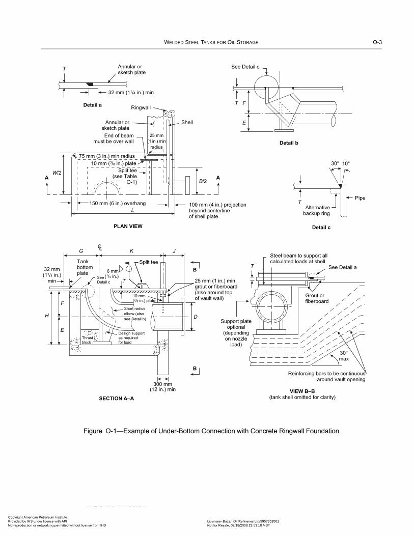
WELDED STEEL TANKS FOR OIL STORAGE O-3
Copyright AmericaProvided by IHS uNo reproduction o
Figure O-1—Example of Under-Bottom Connection with Concrete Ringwall Foundation
Annular orsketch plate
32 mm (11/4 in.) min
T
Detail a
PLAN VIEW
Detail b
Detail c
VIEW B–B
(tank shell omitted for clarity)SECTION A–A
See Detail c
T F
E
PipeT
Alternativebackup ring
30° 10°
Steel beam to support allcalculated loads at shell
See Detail a
Grout orfiberboard
T
30°max
Support plateoptional
(dependingon nozzle
load)
300 mm(12 in.) min
Ringwall
Annular orsketch plate
End of beammust be over wall
25 mm
(1 in.) min
radius
Shell
75 mm (3 in.) min radius
150 mm (6 in.) overhang 100 mm (4 in.) projectionbeyond centerlineof shell plate
Split tee(see Table
O-1) B/2AA
W/2
L
B
B
G K J
D
E
F
H
32 mm(11/4 in.)
min T
Split tee
10 mm(3/8 in.) plate
Tankbottomplate
SeeDetail c
Design supportas requiredfor load
Thrustblock
Short radius
elbow (also
see Detail b)
25 mm (1 in.) mingrout or fiberboard(also around topof vault wall)
6 mm(1/4 in.)
Reinforcing bars to be continuousaround vault opening
CL
10 mm (3/8 in.) plate
n Petroleum Institute nder license with API Licensee=Bazan Oil Refineries Ltd/5957352001
Not for Resale, 02/18/2008 23:53:18 MSTr networking permitted without license from IHS
--``,,,,,,`,,`,`,`,``,,````,,``-`-`,,`,,`,`,,`---

O-4 API STANDARD 650
Copyright AmProvided by No reproduc
Figure O-2—Example of Under-Bottom Connection with Concrete Ringwall Foundation and Improved Tank Bottom and Shell Support
Detail a
VIEW B–BSECTION A–A
See Detail b
F
E
Pipe
Alternative backup ring 30° 10°
30°max
Annular plate (see note)
Shell plate
B/2A
B
B
K
J
D
13 mm(1/2 in.) min
Reinforcing bars to be continuousaround vault opening
Ringwall
Tank bottom
A
Grout
Detail b
PARTIAL PLAN VIEW
As required for clearance
Tank bottom
25 mm(1 in.) min
E
Thrust block Design support asrequired to support load
See alsoDetail a
Annularplate
(see note)SandGrout
Nozzle supportoptional
(depending on load)
As r
eq
uire
dfo
r d
eta
il
Slab roof to be designedto carry liquid load overthe opening
CL
See Detail b
Sand
Note: If sketch plates are used, a full plate shall be located over the vault.
erican Petroleum Institute IHS under license with API Licensee=Bazan Oil Refineries Ltd/5957352001
Not for Resale, 02/18/2008 23:53:18 MSTtion or networking permitted without license from IHS
--``,,,,,,`,,`,`,`,``,,````,,``-`-`,,`,,`,`,,`---

WELDED STEEL TANKS FOR OIL STORAGE O-5
Copyright AmericaProvided by IHS uNo reproduction o
Figure O-3—Example of Under-Bottom Connection with Earth-Type Foundation
1.2 m (4 ft )
300 mm (12 in.) min
3 m (10 ft) min
Tank shell
75 mm (3 in.) min of compacted crushedstone, screenings, fine gravel, clean
sand, or similar material
Tank bottom
150 mm (6 in.) of oiled sand
Centerline
Coarse stoneor gravel
1.5
1
75 mm (3 in.) min of compacted crushedstone, screenings, fine gravel, cleansand, or similar material
Thoroughly compacted fill ofgravel, coarse sand, orother stable material
150 mm (6 in.) layer of oiled sand
Protective coating for piping
2
1
Undisturbed soil
Bevel pipe after cutoff
Bottom plate
Alternative backup ringAlternative backup ring
Bottom plateBottom plate
30° min
Pipe OD
Thoroughly compacted fill ofgravel, coarse sand, or
other stable material
Tank bottom
300 mm(12 in.) min
See Detail a
See Detail b
Slope 25 mm (1 in.)in 1.5 m (60 in.)
45°
Undisturbed soil
2
1
C
C
Detail a Detail b
SECTION C–C
Note: This type of connection shall not be used for tanks with a diameter of less than 6 m (20 ft).
n Petroleum Institute nder license with API Licensee=Bazan Oil Refineries Ltd/5957352001
Not for Resale, 02/18/2008 23:53:18 MSTr networking permitted without license from IHS
--``,,,,,,`,,`,`,`,``,,````,,``-`-`,,`,,`,`,,`---

Copyright AmProvided by No reproduc
--``,,,,,,`,,`,`,`,``,,````,,``-`-`,,`,,`,`,,`---
erican Petroleum Institute IHS under license with API Licensee=Bazan Oil Refineries Ltd/5957352001
Not for Resale, 02/18/2008 23:53:18 MSTtion or networking permitted without license from IHS

•07
•
•
Copyright AmericaProvided by IHS uNo reproduction o
APPENDIX P—ALLOWABLE EXTERNAL LOADS ON TANK SHELL OPENINGS
P.1 IntroductionThis appendix shall be used (unless specified otherwise by the Purchaser on Line 29 of the Data Sheet) for tanks larger than 36 m(120 ft) in diameter, and only when specified by the Purchaser for tanks 36 m (120 ft) in diameter and smaller. See W.2(5) foradditional requirements.This appendix presents two different procedures to determine external loads on tank shells. Section P.2 establishes limit loads andP.3 is based on allowable stresses. This appendix is based on H. D. Billimoria and J. Hagstrom’s “Stiffness Coefficients andAllowable Loads for Nozzles in Flat Bottom Storage Tanks” and H. D. Billimoria and K. K. Tam’s “Experimental Investigationof Stiffness Coefficients and Allowable Loads for a Nozzle in a Flat Bottom Storage Tank.”
P.2 Limit LoadsP.2.1 SCOPE
This appendix establishes requirements for the design of storage-tank openings that conform to Table 5-6 and will be subjected toexternal piping loads. The requirements of this appendix represent accepted practice for the design of shell openings in the lowerhalf of the bottom shell course that have a minimum elevation from the tank bottom and meet the requirements of Table 5-6. It isrecognized that the Purchaser may specify other procedures, special factors, and additional requirements. Any deviation from theserequirements shall be mutually agreed upon by the Purchaser and the Manufacturer.
P.2.2 GENERAL
The design of an external piping system that will be connected to a thin-walled, large-diameter cylindrical vertical storage tankmay pose a problem in the analysis of the interface between the piping system and the tank opening connections. The pipingdesigner must consider the stiffness of the tank shell and the radial deflection and meridional rotation of the shell opening at theopening-shell connection resulting from product head, pressure, and uniform or differential temperature between the shell and thebottom. The work of the piping designer and the tank designer must be coordinated to ensure that the piping loads imposed on theshell opening by the connected piping are within safe limits. Although three primary forces and three primary moments may beapplied to the mid-surface of the shell at an opening connection, only one force, FR, and two moments, ML and MC, are normallyconsidered significant causes of shell deformation (see P.2.3 for a description of the nomenclature).
P.2.3 NOMENCLATURE
a = outside radius of the opening connection (mm) (in.)
E = modulus of elasticity (MPa) (lbf/in.2) (see Table P-1)
FR = radial thrust applied at the mid-surface of the tank shell at the opening connection (N) (lbf)
FP = pressure end load on the opening for the pressure resulting from the design product head at the elevation of the opening centerline, πa2P (N) (lbf)
G = design specific gravity of the liquid
H = maximum allowable tank filling height (mm) (in.)
KC = stiffness coefficient for the circumferential moment (N-mm/radian) (in.-lbf/radian)
KL = stiffness coefficient for the longitudinal moment (N-mm/radian) (in.-lbf/radian)
KR = stiffness coefficient for the radial thrust load (N/mm) (lbf/in.)
L = vertical distance from the opening centerline to the tank bottom (mm) (in.)
MC = circumferential moment applied to the mid-surface of the tank shell (N-mm) (in.-lbf)
ML = longitudinal moment applied to the mid-surface of the tank shell (N-mm) (in.-lbf)
P-1n Petroleum Institute nder license with API Licensee=Bazan Oil Refineries Ltd/5957352001
Not for Resale, 02/18/2008 23:53:18 MSTr networking permitted without license from IHS
--``,,,,,,`,,`,`,`,``,,````,,``-`-`,,`,,`,`,,`---

P-2 API STANDARD 650
Copyright AmProvided by No reproduc
--``,,,,,,`,,`,`,`,``,,````,,``-`-`,,`,,`,`,,`---
P = pressure resulting from product head at the elevation of the opening centerline (MPa) (lbf/in.2)
R = nominal tank radius (mm) (in.)
t = shell thickness at the opening connection (mm) (in.)
ΔT = normal design temperature minus installation temperature (°C) (°F)
W = unrestrained radial growth of the shell (mm) (in.)
WR = resultant radial deflection at the opening connection (mm) (in.)
XA = L + a (mm) (in.)
XB = L – a (mm) (in.)
XC = L (mm) (in.)
YC = coefficient determined from Figure P-4B
YF, YL = coefficients determined from Figure P-4A
α = thermal expansion coefficient of the shell material (mm/[mm-°C]) (in./[in.-°F]) (see Table P-1)
β = characteristic parameter, 1.285/(Rt)0.5 (1/mm) (1/in.)
λ = a/(Rt)0.5
θ = unrestrained shell rotation resulting from product head (radians)
θC = shell rotation in the horizontal plane at the opening connection resulting from the circumferential moment (radians)
θL = shell rotation in the vertical plane at the opening connection resulting from the longitudinal moment (radians)
P.2.4 STIFFNESS COEFFICIENTS FOR OPENING CONNECTIONS
The stiffness coefficients KR, KL, and KC corresponding to the piping loads FR, ML, and MC at an opening connection, as shownin Figure P-1, shall be obtained by the use of Figures P-2A through P-2L. Figures P-2A through P-2L shall be used to interpolateintermediate values of coefficients.
P.2.5 SHELL DEFLECTION AND ROTATION
P.2.5.1 Radial Growth of Shell
The unrestrained outward radial growth of the shell at the center of the opening connection resulting from product head and/orthermal expansion shall be determined as follows:
Table P-1—Modulus of Elasticity and Thermal Expansion Coefficient at the Design Temperature
Design Temperature Modulus of Elasticity MPa (lbf/in.2)
E
Thermal Expansion Coefficienta(mm × 10–6/[mm-°C]) (in. × 10–6 per in.-°F)°C °F
20 70 203,000 (29,500,000) —
93 200 199,000 (28,800,000) 12.0 (6.67)
150 300 195,000 (28,300,000) 12.4 (6.87)
200 400 191,000 (27,700,000) 12.7 (7.07)
260 500 188,000 (27,300,000) 13.1 (7.25)
aMean coefficient of thermal expansion, going from 20°C (70°F) to the temperature indicated.Note: Linear interpolation may be applied for intermediate values.
erican Petroleum Institute IHS under license with API Licensee=Bazan Oil Refineries Ltd/5957352001
Not for Resale, 02/18/2008 23:53:18 MSTtion or networking permitted without license from IHS
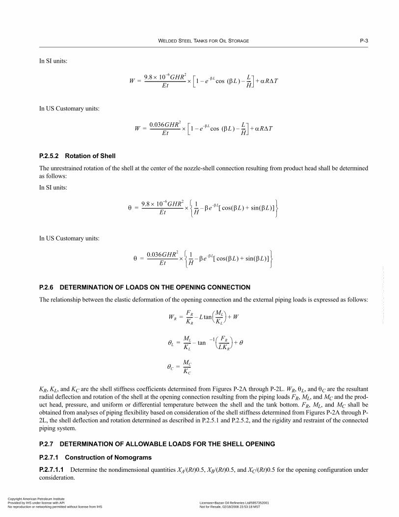
WELDED STEEL TANKS FOR OIL STORAGE P-3
Copyright AmericaProvided by IHS uNo reproduction o
--``,,,,,,`,,`,`,`,``,,````,,``-`-`,,`,,`,`,,`---
In SI units:
In US Customary units:
P.2.5.2 Rotation of Shell
The unrestrained rotation of the shell at the center of the nozzle-shell connection resulting from product head shall be determinedas follows:
In SI units:
In US Customary units:
P.2.6 DETERMINATION OF LOADS ON THE OPENING CONNECTION
The relationship between the elastic deformation of the opening connection and the external piping loads is expressed as follows:
KR, KL, and KC are the shell stiffness coefficients determined from Figures P-2A through P-2L. WR, θL, and θC are the resultantradial deflection and rotation of the shell at the opening connection resulting from the piping loads FR, ML, and MC and the prod-uct head, pressure, and uniform or differential temperature between the shell and the tank bottom. FR, ML, and MC shall beobtained from analyses of piping flexibility based on consideration of the shell stiffness determined from Figures P-2A through P-2L, the shell deflection and rotation determined as described in P.2.5.1 and P.2.5.2, and the rigidity and restraint of the connectedpiping system.
P.2.7 DETERMINATION OF ALLOWABLE LOADS FOR THE SHELL OPENING
P.2.7.1 Construction of Nomograms
P.2.7.1.1 Determine the nondimensional quantities XA/(Rt)0.5, XB/(Rt)0.5, and XC/(Rt)0.5 for the opening configuration underconsideration.
W 9.8 10 6–× GHR2
Et-------------------------------------- 1 e βL– (βL ) L
H----–cos–× αRΔT+=
W 0.036GHR2
Et---------------------------- 1 e βL– (βL ) L
H----–cos–× αRΔT+=
θ 9.8 10 6–× GHR2
Et-------------------------------------- 1
H---- βe βL– βL( ) βL( )sin+cos[ ]–
⎩ ⎭⎨ ⎬⎧ ⎫
×=
θ 0.036GHR2
Et---------------------------- 1
H---- βe βL– βL( ) βL( )sin+cos[ ]–
⎩ ⎭⎨ ⎬⎧ ⎫
×=
WRFR
KR------ L
ML
KL-------⎝ ⎠
⎛ ⎞tan– W+=
θLML
KL------- 1– FR
LKR----------⎝ ⎠
⎛ ⎞tan– θ+=
θCMC
KC-------=
n Petroleum Institute nder license with API Licensee=Bazan Oil Refineries Ltd/5957352001
Not for Resale, 02/18/2008 23:53:18 MSTr networking permitted without license from IHS

P-4 API STANDARD 650
•
Copyright AmProvided by No reproduc
--``,,,,,,`,,`,`,`,``,,````,,``-`-`,,`,,`,`,,`---
P.2.7.1.2 Lay out two sets of orthogonal axes on graph paper, and label the abscissas and ordinates as shown in Figures P-3Aand P-3B, where YC, YF, and YL are coefficients determined from Figures P-4A and P-4B.
P.2.7.1.3 Lay out two sets of orthogonal axes on graph paper, and label the abscissas and ordinates as shown in Figures P-3Aand P-3B, where YC, YF, and YL are coefficients determined from Figures P-4A and P-4B.
P.2.7.1.4 Construct four boundaries for Figure P-3A and two boundaries for Figure P-3B. Boundaries b1 and b2 shall be con-structed as lines at 45-degree angles between the abscissa and the ordinate. Boundaries c1, c2, and c3 shall be constructed as linesat 45-degree angles passing through the calculated value indicated in Figures P-3A and P-3B plotted on the positive x axis.
P.2.7.2 Determination of Allowable Loads
P.2.7.2.1 Use the values for FR, ML, and MC obtained from the piping analyses to determine the quantities (λ/2YF) (FR/FP),(λ/aYL)(ML/FP), and (λ/aYC)(MC/FP).
P.2.7.2.2 Plot the point (λ/2YF)(FR/FP), (λ/aYL)(ML/FP) on the nomogram constructed as shown in Figure P-5A.
P.2.7.2.3 Plot the point (λ/2YF)(FR/FP), (λ/aYC)(MC/FP) on the nomogram constructed as shown in Figure P-5B.
P.2.7.2.4 The external piping loads FR, ML, and MC to be imposed on the shell opening are acceptable if both points deter-mined from P.2.7.2.2 and P.2.7.2.3 lie within the boundaries of the nomograms constructed for the particular opening-tankconfiguration.
P.2.8 MANUFACTURER AND PURCHASER RESPONSIBILITYP.2.8.1 The Manufacturer is responsible for furnishing to the Purchaser the shell stiffness coefficients (see P.2.4) and the unre-strained shell deflection and rotation (see P.2.5). The Purchaser is responsible for furnishing to the Manufacturer the magnitude of
Figure P-1—Nomenclature for Piping Loads and Deformation
FR
RADIAL LOAD FR
LONGITUDINAL MOMENT ML
CIRCUMFERENTIALMOMENT MC
R
X C
θL = ML/KL
X B
X A L
2a
t
L
L
WRM (−)
WRF (+)
θL (+)
θL (−)
θC = MC/KC
(+)θC
+MC
D
D
DWRF = FR/KR
θL = tan−1 (WR/L)
WRM = (− L) tan (θL)MT = MX
X
MC = MY
FL = FY
M L = M
Z
FR = FX
Z
Y
erican Petroleum Institute IHS under license with API Licensee=Bazan Oil Refineries Ltd/5957352001
Not for Resale, 02/18/2008 23:53:18 MSTtion or networking permitted without license from IHS

WELDED STEEL TANKS FOR OIL STORAGE P-5
Copyright AmericaProvided by IHS uNo reproduction o
Figure P-2A—Stiffness Coefficient for Radial Load:Reinforcement on Shell (L/2a = 1.0)
Figure P-2B—Stiffness Coefficient for Longitudinal Moment:Reinforcement on Shell (L/2a = 1.0)
1 × 10⁻⁶
300
Stif
fnes
s co
effic
ient
KR/E
× (2
a) fo
r rad
ial l
oad
on n
ozzl
e
400
500
600
700
800
900
1000
2000
3000
1 × 10⁻⁵
1 × 10⁻⁴
1 × 10⁻³
1 × 10⁻²
Reinforcement on shell
a /R = 0.005
a /R = 0.02
a /R = 0.04
R / t
L/2a = 1.0
1 × 10⁻⁶
300
Stif
fnes
s co
effic
ient
KL/E
× (
2a)3 f
or lo
ngitu
dina
l mom
ent
400
500
600
700
800
900
1000
2000
3000
1 × 10⁻⁵
1 × 10⁻⁴
1 × 10⁻³
1 × 10⁻²
Reinforcement on shell
a /R = 0.005
a /R = 0.02
a /R = 0.04
R / t
L/2a = 1.0
n Petroleum Institute
--``,,,,,,`,,`,`,`,``,,````,,``-`-`,,`,,`,`,,`---
nder license with API Licensee=Bazan Oil Refineries Ltd/5957352001 Not for Resale, 02/18/2008 23:53:18 MSTr networking permitted without license from IHS
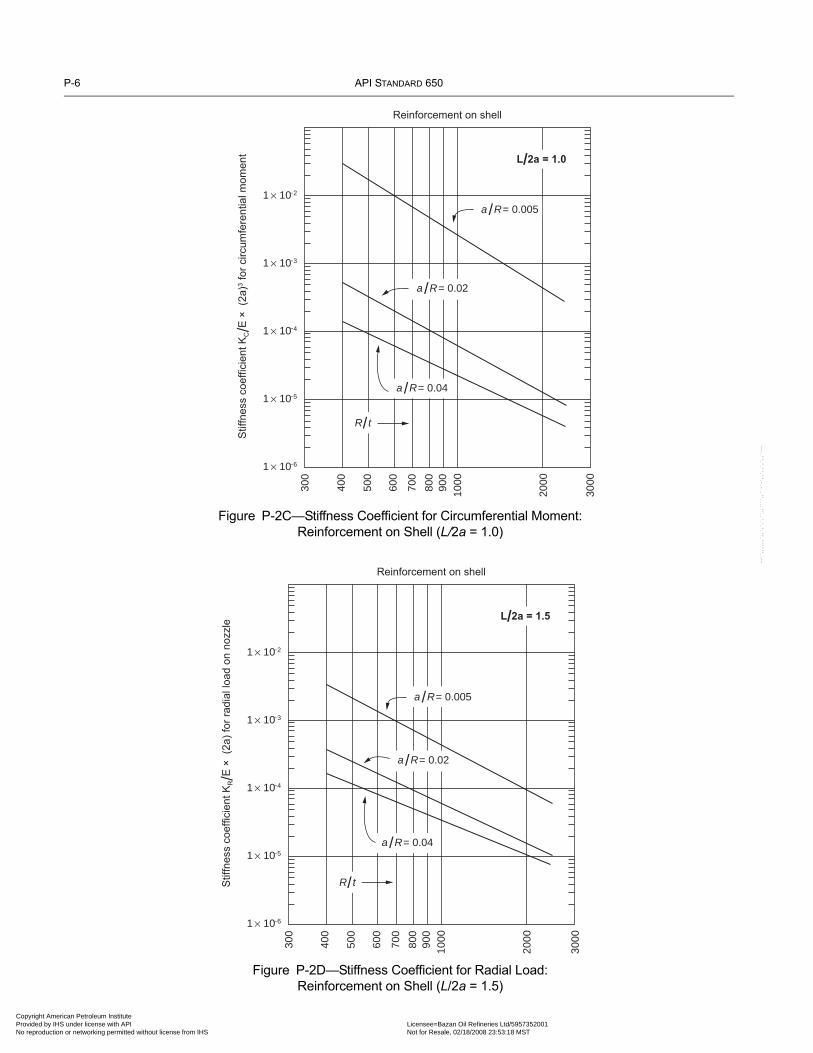
P-6 API STANDARD 650
Copyright AmProvided by No reproduc
--``,,,,,,`,,`,`,`,``,,````,,``-`-`,,`,,`,`,,`---
Figure P-2C—Stiffness Coefficient for Circumferential Moment:Reinforcement on Shell (L/2a = 1.0)
Figure P-2D—Stiffness Coefficient for Radial Load:Reinforcement on Shell (L/2a = 1.5)
1 × 10⁻⁶
300
Stif
fnes
s co
effic
ient
KC/E
× (
2a)3 f
or c
ircum
fere
ntia
l mom
ent
400
500
600
700
800
900
1000
2000
3000
1 × 10⁻⁵
1 × 10⁻⁴
1 × 10⁻³
1 × 10⁻²
Reinforcement on shell
a /R = 0.005
a /R = 0.02
a /R = 0.04
R / t
L/2a = 1.0
1 × 10⁻⁶
300
Stif
fnes
s co
effic
ient
KR/E
× (
2a) f
or ra
dial
load
on
nozz
le
400
500
600
700
800
900
1000
2000
3000
1 × 10⁻⁵
1 × 10⁻⁴
1 × 10⁻³
1 × 10⁻²
Reinforcement on shell
a /R = 0.005
a /R = 0.02
a /R = 0.04
R / t
L/2a = 1.5
erican Petroleum Institute
IHS under license with API Licensee=Bazan Oil Refineries Ltd/5957352001Not for Resale, 02/18/2008 23:53:18 MSTtion or networking permitted without license from IHS

WELDED STEEL TANKS FOR OIL STORAGE P-7
Copyright AmericaProvided by IHS uNo reproduction o
Figure P-2E—Stiffness Coefficient for Longitudinal Moment:Reinforcement on Shell (L/2a = 1.5)
Figure P-2F—Stiffness Coefficient for Circumferential Moment:Reinforcement on Shell (L/2a = 1.5)
1 × 10⁻⁶
300
Stif
fnes
s co
effic
ient
KL/E
× (
2a)3 f
or lo
ngitu
dina
l mom
ent
400
500
600
700
800
900
1000
2000
3000
1 × 10⁻⁵
1 × 10⁻⁴
1 × 10⁻³
1 × 10⁻²
Reinforcement on shell
a /R = 0.005
a /R = 0.02
a /R = 0.04
R / t
L/2a = 1.5
1 × 10⁻⁶
300
Stif
fnes
s co
effic
ient
KC/E
× (2
a)3 f
or c
ircum
fere
ntia
l mom
ent
400
500
600
700
800
900
1000
2000
3000
1 × 10⁻⁵
1 × 10⁻⁴
1 × 10⁻³
1 × 10⁻²
Reinforcement on shell
a /R = 0.005
a /R = 0.02
a /R = 0.04
R / t
L/2a = 1.5
--``,,,,,,`,,`,`,`,``,,````,,``-`-`,,`,,`,`,,`---
n Petroleum Institute nder license with API Licensee=Bazan Oil Refineries Ltd/5957352001
Not for Resale, 02/18/2008 23:53:18 MSTr networking permitted without license from IHS

P-8 API STANDARD 650
Copyright AmProvided by No reproduc
--``,,,,,,`,,`,`,`,``,,````,,``-`-`,,`,,`,`,,`---
Figure P-2G—Stiffness Coefficient for Radial Load:Reinforcement in Nozzle Neck Only (L/2a = 1.0)
Figure P-2H—Stiffness Coefficient for Longitudinal Moment:Reinforcement in Nozzle Neck Only (L/2a = 1.0)
1 × 10⁻⁶
300
Stif
fnes
s co
effic
ient
KR/E
× (2
a) fo
r rad
ial l
oad
on n
ozzl
e
400
500
600
700
800
900
1000
2000
3000
1 × 10⁻⁵
1 × 10⁻⁴
1 × 10⁻³
1 × 10⁻²
Reinforcement on opening (neck) only
a /R = 0.005
a /R = 0.02
a /R = 0.04
R / t
L/2a = 1.0
1 × 10⁻⁶
300
Stif
fnes
s co
effic
ient
KL/E
× (2
a)3 f
or lo
ngitu
dina
l mom
ent
400
500
600
700
800
900
1000
2000
3000
1 × 10⁻⁵
1 × 10⁻⁴
1 × 10⁻³
1 × 10⁻²
Reinforcement on opening (neck) only
a /R = 0.005
a /R = 0.02
a /R = 0.04
R / t
L/2a = 1.0
erican Petroleum Institute IHS under license with API Licensee=Bazan Oil Refineries Ltd/5957352001
Not for Resale, 02/18/2008 23:53:18 MSTtion or networking permitted without license from IHS

WELDED STEEL TANKS FOR OIL STORAGE P-9
Copyright AmericaProvided by IHS uNo reproduction o
--``,,,,,,`,,`,`,`,``,,````,,``-`-`,,`,,`,`,,`---
Figure P-2I—Stiffness Coefficient for Circumferential Moment:Reinforcement in Nozzle Neck Only (L/2a = 1.0)
Figure P-2J—Stiffness Coefficient for Radial Load:Reinforcement in Nozzle Neck Only (L/2a = 1.5)
1 × 10⁻⁶
300
Stif
fnes
s co
effic
ient
KC/E
× (
2a)3 f
or c
ircum
fere
ntia
l mom
ent
400
500
600
700
800
900
1000
2000
3000
1 × 10⁻⁵
1 × 10⁻⁴
1 × 10⁻³
1 × 10⁻²
Reinforcement on opening (neck) only
a /R = 0.005
a /R = 0.02
a /R = 0.04R / t
L/2a = 1.0
1 × 10⁻⁶
300
Stif
fnes
s co
effic
ient
KR/E
× (
2a) f
or ra
dial
load
on
nozz
le
400
500
600
700
800
900
1000
2000
3000
1 × 10⁻⁵
1 × 10⁻⁴
1 × 10⁻³
1 × 10⁻²
Reinforcement on opening (neck) only
a /R = 0.005
a /R = 0.02
a /R = 0.04
R / t
L/2a = 1.5
n Petroleum Institute nder license with API Licensee=Bazan Oil Refineries Ltd/5957352001
Not for Resale, 02/18/2008 23:53:18 MSTr networking permitted without license from IHS

P-10 API STANDARD 650
Copyright AmProvided by No reproduc
--``,,,,,,`,,`,`,`,``,,````,,``-`-`,,`,,`,`,,`---
Figure P-2K—Stiffness Coefficient for Longitudinal Moment:Reinforcement in Nozzle Neck Only (L/2a = 1.5)
Figure P-2L—Stiffness Coefficient for Circumferential Moment:Reinforcement in Nozzle Neck Only (L/2a = 1.5)
1 × 10⁻⁶
300
Stif
fnes
s co
effic
ient
KL/E
× (
2a)3 f
or lo
ngitu
dina
l mom
ent
400
500
600
700
800
900
1000
2000
3000
1 × 10⁻⁵
1 × 10⁻⁴
1 × 10⁻³
1 × 10⁻²
Reinforcement on opening (neck) only
a /R = 0.005
a /R = 0.02
a /R = 0.04
R / t
L/2a = 1.5
1 × 10⁻⁶
300
Stif
fnes
s co
effic
ient
KC/E
× (
2a)3 f
or c
ircum
fere
ntia
l mom
ent
400
500
600
700
800
900
1000
2000
3000
1 × 10⁻⁵
1 × 10⁻⁴
1 × 10⁻³
1 × 10⁻²
Reinforcement on opening (neck) only
a /R = 0.005
a /R = 0.02
a /R = 0.04
R / t
L/2a = 1.5
erican Petroleum Institute IHS under license with API Licensee=Bazan Oil Refineries Ltd/5957352001
Not for Resale, 02/18/2008 23:53:18 MSTtion or networking permitted without license from IHS

WELDED STEEL TANKS FOR OIL STORAGE P-11
•
Copyright AmericaProvided by IHS uNo reproduction o
the shell-opening loads (see P.2.6). The Manufacturer shall determine, in accordance with P.2.7, the acceptability of the shell-opening loads furnished by the Purchaser. If the loads are excessive, the piping configuration shall be modified so that the shell-opening loads fall within the boundaries of the nomograms constructed as in P.2.7.1.
P.2.8.2 Changing the elevation of the opening and changing the thickness of the shell are alternative means of reducingstresses, but because these measures can affect fabrication, they may be considered only if mutually agreed upon by the Purchaserand the Manufacturer.
P.2.9 SAMPLE PROBLEM
P.2.9.1 Problem
A tank is 80 m (260 ft) in diameter and 19.2 m (64 ft) high, and its bottom shell course is 34 mm (1.33 in.) thick. The tank has alow-type nozzle with an outside diameter of 610 mm (24 in.) in accordance with API Std 650, and the nozzle centerline is630 mm (24.75 in.) up from the bottom plate, with reinforcement on the opening (neck) only (see Figure P-6). What are the endconditions (W, θ, KR, KL, and KC) for an analysis of piping flexibility? What are the limit loads for the nozzle?
a = 305 mm (12 in.),L = 630 mm (24.75 in.),H = 19,200 mm (64 × 12 = 768 in.),
ΔT = 90 – 20 = 70°C (200 – 70 = 130°F),R = 80,000/2 = 40,000 mm ((260 × 12)/2 = 1560 in.),t = 34 mm (1.33 in.).
P.2.9.2 Solution
P.2.9.2.1 Calculate the stiffness coefficients for the nozzle-tank connection:
R / t = 40,000/34 = 1176 (1560/1.33 = 1173)a / R = 305/40,000 = 0.008 (12/1560 = 0.008)
L / 2a = 630/610 @ 1.0 (24.75/24 @ 1.0)
For the radial load (from Figure P-2G),
In SI units:
KR = (3.1 × 10⁻⁴)(199,000 N/mm2)(610 mm)= 37.6 N/mm
In US Customary units:
KR = (3.1 × 10⁻⁴)(28.8 × 10⁶ lb/in.2)(24 in.)
= 214 × 103 lbf/in.For the longitudinal moment (from Figure P-2H),In SI units:
KL = (3.0 × 10⁻⁴)(199,000 N/mm2)(610 mm)
= 13.6 × 10⁹ N-mm/rad
KR
E 2a( )--------------- 3.1 10 4–×=
KR
E 2a( )--------------- 3.1 10 4–×=
KL
E 2a( )3----------------- 3.0 10 4–×=
n Petroleum Institute nder license with API Licensee=Bazan Oil Refineries Ltd/5957352001
Not for Resale, 02/18/2008 23:53:18 MSTr networking permitted without license from IHS
--``,,,,,,`,,`,`,`,``,,````,,``-`-`,,`,,`,`,,`---

P-12 API STANDARD 650
Copyright AmProvided by No reproduc
Figure P-3A—Construction of Nomogram for b1, b2, c1, c2 Boundary
Figure P-3B—Construction of Nomogram for b1, c3 Boundary
0.1 or[1.0 – 0.75 X B / (R t )0.5 ],whichever is greater
(λ / 2YF ) (FR /FP)
0.1 or[1.0 – 0.75 X A / (R t )0.5 ],whichever is greater
(λ /aYL ) (M L /FP)
1.0
–1.0 0.5 1.0
0.5
– 0.5
–1.0
1
1
1
1
1
11
1
c 1
b 2
c 2
b 1
– 0.5
0.1 or[1.0 – 0.75 X C / (R t )0.5 ],whichever is greater
(λ / 2YF ) (FR /FP)
(λ /aYC ) (MC /FP)
1.0
–1.0 0.5 1.0
1
11
1
c 3
b 1
– 0.5
0.5
--``,,,,,,`,,`,`,`,``,,````,,``-`-`,,`,,`,`,,`---
erican Petroleum Institute IHS under license with API Licensee=Bazan Oil Refineries Ltd/5957352001
Not for Resale, 02/18/2008 23:53:18 MSTtion or networking permitted without license from IHS

WELDED STEEL TANKS FOR OIL STORAGE P-13
Copyright AmericaProvided by IHS uNo reproduction o
In US Customary units:
KL = (3.0 × 10⁻⁴)(28.8 × 10⁶)(24)3
= 119 × 106 in.-lb/rad
For the circumferential moment (from Figure P-2I),
In SI units:
KC = (5.0 × 10⁻⁴)(199,000 N/mm2)(610 mm)3
= 22.6 × 10⁹ N-mm/rad
In US Customary units:
KC = (5.0 × 10⁻⁴)(28.8 × 10⁶)(24)3
= 199 × 106 in.-lb/rad
Figure P-4A—Obtaining Coefficients YF and YL
YF
or
YL
λ = a / (Rt ) 0.5 = (a / R) (R / t ) 0.5
0.1
Two-thirds of the required reinforced area must be locatedwithin a + 0.5 (Rt )0.5 of the opening centerline
0.7
1
0.2 0.3 0.5 1.0 2.0
2
5
10
20
30
YL
YF
KL
E 2a( )3----------------- 3.0 10 4–×=
KC
E 2a( )3----------------- 5.0 10 4–×=
KC
E 2a( )3----------------- 5.0 10 4–×=
n Petroleum Institute nder license with API Licensee=Bazan Oil Refineries Ltd/5957352001
Not for Resale, 02/18/2008 23:53:18 MSTr networking permitted without license from IHS
--``,,,,,,`,,`,`,`,``,,````,,``-`-`,,`,,`,`,,`---

P-14 API STANDARD 650
Copyright AmProvided by No reproduc
Figure P-4B—Obtaining Coefficient YC
YC
λ = a / (Rt ) 0.5 = (a / R) (R / t ) 0.5
0.11
2
0.2 0.3 0.5 1.0 2.0
3
5
10
20
30
Two-thirds of the required reinforced area must be locatedwithin a + 0.5 (Rt )0.5 of the opening centerline
3.0 5.0 10.0
50
100
200
300
500
1000
erican Petroleum Institute IHS under license with API Licensee=Bazan Oil Refineries Ltd/5957352001
Not for Resale, 02/18/2008 23:53:18 MSTtion or networking permitted without license from IHS
--``,,,,,,`,,`,`,`,``,,````,,``-`-`,,`,,`,`,,`---

WELDED STEEL TANKS FOR OIL STORAGE P-15
Copyright AmericaProvided by IHS uNo reproduction o
P.2.9.2.2 Calculate the unrestrained shell deflection and rotation at the nozzle centerline resulting from the hydrostatic head ofthe full tank:
In SI units:
β =
βL = (0.00110)(630) = 0.7 rad
W =
=
+ (12.0 × 10⁻⁶)(40,000)(70)
= 59.77 mm
θ =
=
= –0.032 rad
In US Customary units:
β =
βL = (0.0282)(24.75) = 0.7
W =
=
+ (6.67 × 10⁻⁶)(1560)(130)
= 2.39 in.
1.285Rt( )0.5--------------- 1.285
40,000 34×( )0.5------------------------------------- 0.00110 mm= =
9.8 10 6–× GHR2
Et-------------------------------------- 1 e βL– βL( )cos– L
H----– αRΔT+
9.8 10 6–×( ) 1( ) 19,200( ) 40,000( )2
199,000( ) 34( )---------------------------------------------------------------------------------
1 e 0.7– 0.7( )cos– 63019,200----------------–
9.8 10 6–× GHR2
Et-------------------------------------- 1
H---- βe βL–– βL( )cos βL( )sin+[ ]
⎩ ⎭⎨ ⎬⎧ ⎫
9.8 10 6–×( ) 1( ) 19,200( ) 40,000( )2
199,000( ) 34( )-----------------------------------------------------------------------------------
119,200---------------- 0.0011e 0.7–– 0.7( )cos 0.7( )sin+[ ]
⎩ ⎭⎨ ⎬⎧ ⎫
1.285
Rt( )0.5---------------- 1.2851560 1.33×( )0.5------------------------------------- 0.0282 in.= =
0.036GHR2
Et---------------------------- 1 e βL– βL( )cos– L
H----–
αRΔT+
0.036 1( ) 768( ) 1560( )2
28.8 106×( ) 1.33( )------------------------------------------------------- 1 e 0.7– 0.7( )cos– 24.75
768-------------–
--``,,,,,,`,,`,`,`,``,,````,,``-`-`,,`,,`,`,,`---
n Petroleum Institute nder license with API Licensee=Bazan Oil Refineries Ltd/5957352001
Not for Resale, 02/18/2008 23:53:18 MSTr networking permitted without license from IHS
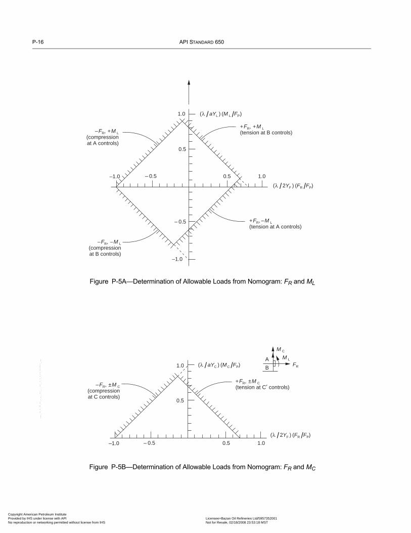
P-16 API STANDARD 650
Copyright AmProvided by No reproduc
Figure P-5A—Determination of Allowable Loads from Nomogram: FR and ML
Figure P-5B—Determination of Allowable Loads from Nomogram: FR and MC
(λ / 2YF ) (FR /FP)
(λ /aYL ) (M L /FP)1.0
–1.0 0.5 1.0
0.5
– 0.5
–1.0
– 0.5
+FR, –M L(tension at A controls)
+FR, +M L(tension at B controls)–FR, +M L
(compressionat A controls)
–FR, –M L(compressionat B controls)
(λ / 2YF ) (FR /FP)
(λ /aYC ) (MC /FP)1.0
–1.0 0.5 1.0– 0.5
+FR, ±M C(tension at C′ controls)–FR, ±M C
(compressionat C controls)
M C
M L
FR
A
B
0.5
--``,,,,,,`,,`,`,`,``,,````,,``-`-`,,`,,`,`,,`---
erican Petroleum Institute IHS under license with API Licensee=Bazan Oil Refineries Ltd/5957352001
Not for Resale, 02/18/2008 23:53:18 MSTtion or networking permitted without license from IHS

WELDED STEEL TANKS FOR OIL STORAGE P-17
Copyright AmericaProvided by IHS uNo reproduction o
θ =
=
= –0.032 rad
Perform the analysis of piping flexibility using W, θ, KR, KL, and KC as the end conditions at the nozzle-to-piping connection.
XA = 935 mm (36.75 in.)
XB = 325 mm (12.75 in.)
XC = 630 mm (24.75 in.)
Determine the allowable loads for the shell opening, as in P.9.2.3.
P.2.9.2.3 Determine the nondimensional quantities:
In SI units:
Figure P-6—Low-Type Nozzle with Reinforcement in Nozzle Neck Only (for Sample Problem)
34 mm (1.33")
2a = 610 mm (24")
L = 630 mm (24.75")
0.036GHR2
Et---------------------------- 1
H---- βe βL–– βL( )cos βL( )sin+[ ]
⎩ ⎭⎨ ⎬⎧ ⎫
0.036 1( ) 768( ) 1560( )2
28.8 106×( ) 1.33( )------------------------------------------------------- 1
768--------- βe 0.7–– 0.7( )cos 0.7( )sin+[ ]
⎩ ⎭⎨ ⎬⎧ ⎫
XA
Rt( )0.5--------------- 93540,000( ) 34( )[ ]0.5----------------------------------------- 0.80= =
XB
Rt( )0.5--------------- 32540,000( ) 34( )[ ]0.5----------------------------------------- 0.28= =
XC
Rt( )0.5--------------- 63040,000( ) 34( )[ ]0.5----------------------------------------- 0.54= =
λ ARt( )0.5--------------- 305
40,000( ) 34( )[ ]0.5----------------------------------------- 0.26= = =
--``,,,,,,`,,`,`,`,``,,````,,``-`-`,,`,,`,`,,`---
n Petroleum Institute nder license with API Licensee=Bazan Oil Refineries Ltd/5957352001
Not for Resale, 02/18/2008 23:53:18 MSTr networking permitted without license from IHS

P-18 API STANDARD 650
Copyright AmProvided by No reproduc
In US Customary units:
From Figures P-4A and P-4B,
YL = 7.8 mm (in.)
YF = 2.0 mm (in.)
YC = 15.0 mm (in.)
P.2.9.2.4 Construct the load nomograms (see Figure P-7):
In SI units:
= 53,200 N
XA
Rt( )0.5--------------- 36.751560( ) 1.33( )[ ]0.5----------------------------------------- 0.81= =
XB
Rt( )0.5--------------- 12.751560( ) 1.33( )[ ]0.5----------------------------------------- 0.28= =
XC
Rt( )0.5--------------- 24.751560( ) 1.33( )[ ]0.5----------------------------------------- 0.54= =
λ ARt( )0.5--------------- 12
1560( ) 1.33( )[ ]0.5----------------------------------------- 0.26= = =
1.0 0.75XB
Rt( )0.5---------------– 1.0 0.75 3251166------------⎝ ⎠
⎛ ⎞– 0.79= =
1.0 0.75XA
Rt( )0.5---------------– 1.0 0.75 9351166------------⎝ ⎠
⎛ ⎞– 0.40= =
1.0 0.75XC
Rt( )0.5---------------– 1.0 0.75 6301166------------⎝ ⎠
⎛ ⎞– 0.59= =
FP Pπa2 9800( ) 1.0( ) 19.2 0.630–( )π 0.305( )2= =
λ2YF---------
FR
FP------⎝ ⎠
⎛ ⎞ 0.262( ) 2.0( )
--------------------FR
53,200----------------⎝ ⎠
⎛ ⎞ 1.22 10 6– FR×= =
λaYL--------
ML
FP-------⎝ ⎠
⎛ ⎞ 0.26305( ) 7.8( )
--------------------------ML
53,200----------------⎝ ⎠
⎛ ⎞ 2.05 10 9– ML×= =
λaYC---------
MC
FP-------⎝ ⎠
⎛ ⎞ 0.26305( ) 15( )
------------------------MC
53,200----------------⎝ ⎠
⎛ ⎞ 1.07 10 9– MC×= =
erican Petroleum Institute IHS under license with API Licensee=Bazan Oil Refineries Ltd/5957352001
Not for Resale, 02/18/2008 23:53:18 MSTtion or networking permitted without license from IHS
--``,,,,,,`,,`,`,`,``,,````,,``-`-`,,`,,`,`,,`---

WELDED STEEL TANKS FOR OIL STORAGE P-19
Copyright AmericaProvided by IHS uNo reproduction o
--``,,,,,,`,,`,`,`,``,,````,,``-`-`,,`,,`,`,,`---
Figure P-7—Allowable-Load Nomograms for Sample Problem
(λ / 2YF ) (FR /FP)
1.0
1
1
1
1
1
1
1
1 1
1
1
1
–1.0 0.5 1.0– 0.5
- 1.0 0.5 1.0- 0.5
– 0.5
–1.0
1.0
0.5
0.79
0.4
0.59
- FR, + M C
(compression at C controls)
- FR, + M C
(compression at C′ controls)
- FR, + ML
(compression at A controls)
FR
- FR, - ML
(compression at B controls)
A
C
B
C′
M L
M C
+ FR, + M C
(tension at C′ controls)
+ FR, - M C
(tension at C controls)
+ FR, - ML
(tension at A controls)
+ FR, + ML
(tension at B controls)
(λ / 2YF ) (FR /FP)
(λ /aYC ) (MC/FP)
(λ /aYL ) (M L /FP)
n Petroleum Institute nder license with API Licensee=Bazan Oil Refineries Ltd/5957352001
Not for Resale, 02/18/2008 23:53:18 MSTr networking permitted without license from IHS

P-20 API STANDARD 650
Copyright AmProvided by No reproduc
In US Customary units:
= 12,142 pounds
P.2.9.2.5 Determine the limiting piping loads.
In SI units:
For ML = 0 and MC = 0,
For FR,
Therefore,
= 328,000 N (tension at A controls)
For ML = 0 and FR = 0,
For MC,
Therefore,
= 550 × 106 N-mm (tension at C′ controls)
For FR = 0 and MC = 0,
For ML,
1.0 0.75XB
Rt( )0.5---------------– 1.0 0.75 12.7545.6-------------⎝ ⎠
⎛ ⎞– 0.79= =
1.0 0.75XA
Rt( )0.5---------------– 1.0 0.75 36.7545.6-------------⎝ ⎠
⎛ ⎞– 0.40= =
1.0 0.75XC
Rt( )0.5---------------– 1.0 0.75 24.7545.6-------------⎝ ⎠
⎛ ⎞– 0.59= =
FP Pπa2 62.4( ) 1.0( )1728
---------------------------
64( ) 12( ) 24.75–[ ]π122= =
λ2YF---------
FR
FP------⎝ ⎠
⎛ ⎞ 0.262( ) 2.0( )
--------------------FR
12,142----------------
⎝ ⎠⎜ ⎟⎛ ⎞
5.35 10 6– FR×= =
λaYL--------
ML
FP-------⎝ ⎠
⎛ ⎞ 0.2612( ) 7.8( )
-----------------------ML
12,142----------------
⎝ ⎠⎜ ⎟⎛ ⎞
229 10 9– ML×= =
λaYC---------
MC
FP-------⎝ ⎠
⎛ ⎞ 0.2612( ) 15( )
---------------------MC
12,142----------------
⎝ ⎠⎜ ⎟⎛ ⎞
119 10 9– MC×= =
λ2YF---------
FR
FP------⎝ ⎠
⎛ ⎞ 1.22 10 6– FR× 0.4≤=
FRmax0.4
1.22 10 6–×-------------------------=
λaYC---------
MC
FP-------⎝ ⎠
⎛ ⎞ 1.07 10 9– MC× 0.59≤=
MCmax0.59
1.07 10 9–×------------------------=
λaYL--------
ML
FP-------⎝ ⎠
⎛ ⎞ 2.05 10 9– ML× 0.79≤=
erican Petroleum Institute IHS under license with API Licensee=Bazan Oil Refineries Ltd/5957352001
Not for Resale, 02/18/2008 23:53:18 MSTtion or networking permitted without license from IHS
--``,,,,,,`,,`,`,`,``,,````,,``-`-`,,`,,`,`,,`---
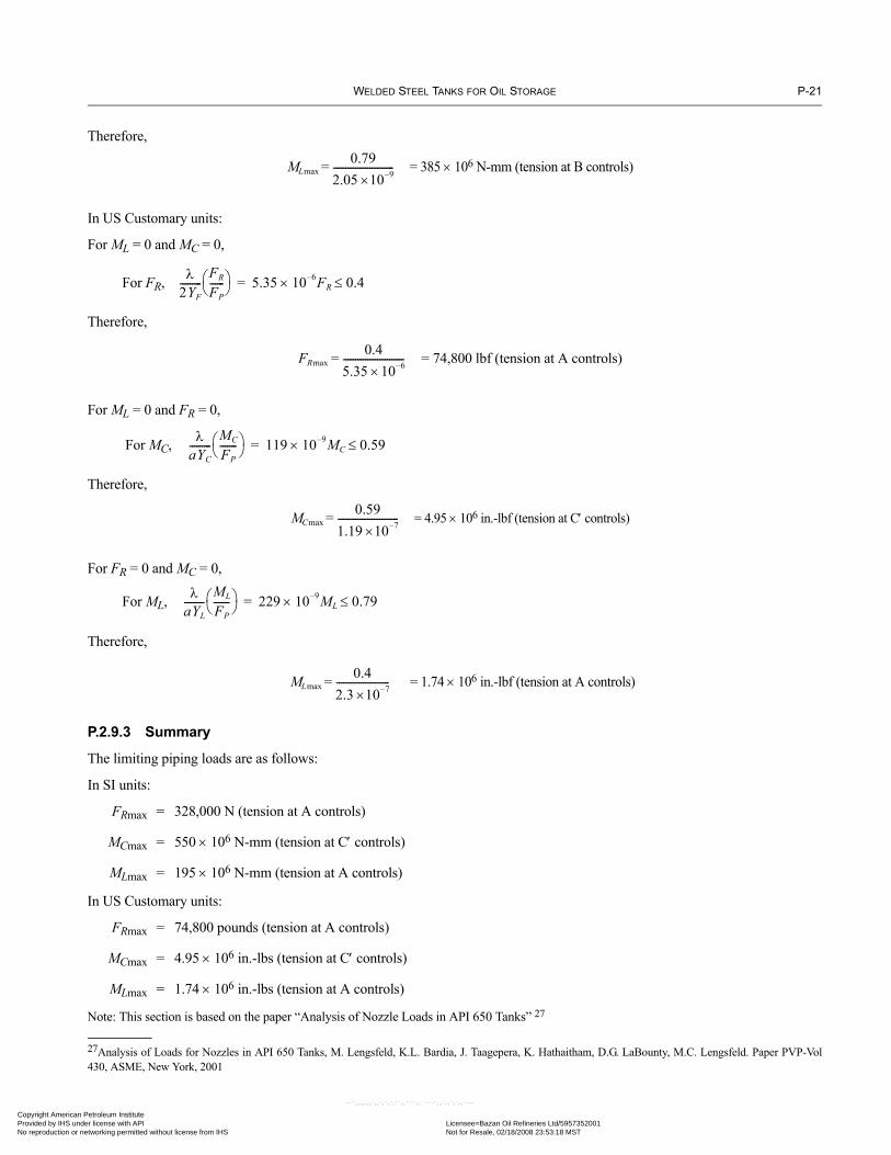
WELDED STEEL TANKS FOR OIL STORAGE P-21
Copyright AmericaProvided by IHS uNo reproduction o
Therefore,
= 385 × 106 N-mm (tension at B controls)
In US Customary units:
For ML = 0 and MC = 0,
For FR,
Therefore,
= 74,800 lbf (tension at A controls)
For ML = 0 and FR = 0,
For MC,
Therefore,
= 4.95 × 106 in.-lbf (tension at C′ controls)
For FR = 0 and MC = 0,
For ML,
Therefore,
= 1.74 × 106 in.-lbf (tension at A controls)
P.2.9.3 Summary
The limiting piping loads are as follows:
In SI units:
FRmax = 328,000 N (tension at A controls)
MCmax = 550 × 106 N-mm (tension at C′ controls)
MLmax = 195 × 106 N-mm (tension at A controls)
In US Customary units:
FRmax = 74,800 pounds (tension at A controls)
MCmax = 4.95 × 106 in.-lbs (tension at C′ controls)
MLmax = 1.74 × 106 in.-lbs (tension at A controls)
Note: This section is based on the paper “Analysis of Nozzle Loads in API 650 Tanks” 27
27Analysis of Loads for Nozzles in API 650 Tanks, M. Lengsfeld, K.L. Bardia, J. Taagepera, K. Hathaitham, D.G. LaBounty, M.C. Lengsfeld. Paper PVP-Vol430, ASME, New York, 2001
MLmax0.79
2.05 10 9–×-------------------------=
λ2YF---------
FR
FP------⎝ ⎠
⎛ ⎞ 5.35 10 6– FR× 0.4≤=
FRmax0.4
5.35 10 6–×-------------------------=
λaYC---------
MC
FP-------⎝ ⎠
⎛ ⎞ 119 10 9– MC× 0.59≤=
MCmax0.59
1.19 10 7–×-------------------------=
λaYL--------
ML
FP-------⎝ ⎠
⎛ ⎞ 229 10 9– ML× 0.79≤=
MLmax0.4
2.3 10 7–×----------------------=
n Petroleum Institute nder license with API Licensee=Bazan Oil Refineries Ltd/5957352001
Not for Resale, 02/18/2008 23:53:18 MSTr networking permitted without license from IHS
--``,,,,,,`,,`,`,`,``,,````,,``-`-`,,`,,`,`,,`---

P-22 API STANDARD 650
Copyright AmProvided by No reproduc
P.3 Alternate Procedure for the Evaluation of External Loads on Tank Shell OpeningsP.3.1 SCOPE
This alternative method expands the data presented in the WRC Bulletin 297. Maximum stress factors are presented in figures aswell as in tables. WRC Bulletin 297 was used to calculate the maximum stress factors fi at the junction of the nozzle and tankshell. The recommended limitations for WRC 297 are D/T ≤ 2500, d/t ≤ 100. The method is valid for all practical sizes of tanks.
P.3.2 NOMENCLATURE
B = 2(Dt)1/2, distance of nozzle removed from any other gross structural stress continuity, (mm) (in.)
D = nominal diameter of tank, (mm) (in.)
Do = diameter of reinforcing plate (mm) (in.)
FR = radial thrust applied at the mid-surface of the tank shell at the opening connection, (N) (lbf)
L = vertical distance from opening centerline to tank bottom, (mm) (in.)
MC = circumferential moment applied to the mid-surface of the tank shell, (N-mm) (in.-lbf)
Mi = generic moment, (N-mm) (in.-lbs)
ML = longitudinal moment applied to the mid-surface of the tank shell, (N-mm) (in.-lbf)
MT = torsional moment applied to the mid-surface of the tank shell, (N-mm) (in.-lbf)
S = stress intensity, (MPa) (lbf/in.2)
Sall = allowable stress intensity due to applied load on nozzles, (MPa) (lbf/in.2)1 × Sd for mechanical loads1.5 × Sd for thermal loads
Sd = allowable design stress, (MPa) (lbf/in.2)
VC = shear force in transverse (circumferential) direction, (N) (lbf)
VL = shear force in longitudinal direction, (N) (lbs)
Wr = resultant radial deflection at opening connection, (mm) (in.)
a = outside radius of opening connection, (mm) (in.)
d = outside diameter of nozzle, (mm) (in.)
fC = stress factor due to circumferential moment, (dimensionless)
fL = stress factor due to longitudinal moment, (dimensionless)
fR = stress factor due to radial thrust, (dimensionless)
fi = stress factor (generic), (dimensionless)
h = L/B, height ratio, (dimensionless)
mr = radial bending stress component, (dimensionless)
m = transverse bending stress component, (dimensionless)
mi = generic bending stress component, (dimensionless)
nr = radial membrane stress component, (dimensionless)
n = transverse (circumferential) membrane stress component, (dimensionless)
--``,,,,,,`,,`,`,`,``,,````,,``-`-`,,`,,`,`,,`---
erican Petroleum Institute IHS under license with API Licensee=Bazan Oil Refineries Ltd/5957352001
Not for Resale, 02/18/2008 23:53:18 MSTtion or networking permitted without license from IHS

WELDED STEEL TANKS FOR OIL STORAGE P-23
Copyright AmericaProvided by IHS uNo reproduction o
ni = generic stress component (membrane), (dimensionless)
t = thickness of tank shell at location of nozzle, (mm) (in.)
tn = thickness of nozzle neck, (mm) (in.)
tr = thickness of reinforcing plate (mm) (in.)
u = (d/D)(D/T)1/2, geometric parameter, (dimensionless)
z = stress reduction factor, (dimensionless)
σr = calculated radial stress, (MPa) (lbf/in.2)
σθ = calculated membrane stress, (MPa) (lbf/in.2)
σi = calculated generic stress, (MPa) (lbf/in.2)
τ = calculated shear stress, (MPa) (lbf/in.2)
P.3.3 DESCRIPTION
Figures P-8 through P-10 provide stress factors for nozzles located away from a gross structural discontinuity. A gross struc-tural discontinuity is defined as a major change of geometry, like a ring or the closeness of the bottom/shell junction. Thestress factors are a combination of membrane and bending components for each load applied. Equations created from the datain WRC Bulletin 297 were used to produce the graphs in Figure P-8 through P-10. The graphs represent the absolute maxi-mum value, which will result in a conservative estimate of the maximum stresses at the nozzle-to-shell junction. Each graphincludes the mathematical expression for the plotted graph. The mathematical equations are summarized in Tables P-2 throughP-4. Use of the mathematical equations will simplify the creation of computer programs for the calculation of stresses at thenozzle-to-shell junction
P.3.4 STRESS FACTORS DUE TO FR, MC, ML
Total stress has three components: bending, membrane, and shear. The stress factors for calculation of stresses in the shell at thenozzle junction have been presented for the stress equations. Moment loads include circumferential and longitudinal moments.
σr = (FR/t2)(nr ± 6mr) (Radial Load) (1)
σθ = (FR/t2)(nθ ± 6mθ) (Radial Load) (2)
σr = [Mi/(dt2)](nr ± 6mr) (Moment Load) (3)
σθ = [Mi/(dt2)](nθ ± 6mθ) (Moment Load) (4)
The dimensionless factors ni and mi were obtained from WRC Bulletin 297, Figures 3 through 58 for various nozzle sizes, tankdiameters and thicknesses. The absolute maximum of these values as used in the stress Equations 1 through 4 have been com-bined into the dimensionless stress factors:
fi = (ni ± 6mi) (5)
The factors were plotted after transformation into mathematical equivalents in Figures P-8 through P-10.The actual maximum stresses for specific nozzles in a tank can be calculated by:
σi = (P/t2) fi for radial load (6a)
n Petroleum Institute nder license with API Licensee=Bazan Oil Refineries Ltd/5957352001
Not for Resale, 02/18/2008 23:53:18 MSTr networking permitted without license from IHS
--``,,,,,,`,,`,`,`,``,,````,,``-`-`,,`,,`,`,,`---

P-24 API STANDARD 650
Copyright AmProvided by No reproduc
and
σi = [Mi /(dt2)] fi for moment load (6b)
P.3.5 SHEAR STRESSES DUE TO MT, VC, VL
Shear stresses in the tank shell at the nozzle junction may be estimated by:
τMT = 2Mi/(πd2t) for torsional moment (7a)
τVi = 2Vi/(πdt) for shear force (7b)
where
Vi = VC or VL
The total shear stress is the summation of the three components:
τTotal = τMT + τVC + τVL (8a)
However, if shear stresses due to VC and VL become significant, it should be recognized that their maximum value and zero valueoccur 90º apart from each other. In this case the components shall be separated into:
τL = τMT + τVL (8b)
and
τC = τMT + τVC (8c)
The larger shear stress from the above expression should be used for combined stresses.
P.3.6 STRESS REDUCTION FACTORS
Stress reduction factors are presented in Figure P-8. These factors compare the values shown in Figures P-8 through P-10 asderived from the equations in Table P-2 through P-4 with values obtained using finite element analysis (FEA) for nozzles closer toa gross structural discontinuity. It should be noted that the stresses decrease as the nozzles move closer to a discontinuity. Depend-ing on the location of the nozzles, the value for the stresses will be multiplied by the stress reduction factor.An array of reduction factors were found, but for simplicity Figure P-8 shows only one line. This line represents conservativereduction factors. Height factors greater than 1 have a ‘z’ value of 1.
P.3.7 COMBINING STRESSES
For stresses due to the different nozzle loads, WRC Bulletin 297 suggests the following equation to calculate the stress intensity.
S = largest absolute magnitude of (9)
= 0.5 [(σr + σ) ± [(σr – σθ) 2 + 4τ2]0.5]
It should be noted that the maximum stresses due to a circumferential moment, MC, and a longitudinal moment, ML, are 90º apart.Thus the maximum stress for the transverse plane is:
σi = σi(FR) + σi (MC) + τi (10a)
erican Petroleum Institute IHS under license with API Licensee=Bazan Oil Refineries Ltd/5957352001
Not for Resale, 02/18/2008 23:53:18 MSTtion or networking permitted without license from IHS
--``,,,,,,`,,`,`,`,``,,````,,``-`-`,,`,,`,`,,`---

WELDED STEEL TANKS FOR OIL STORAGE P-25
Copyright AmericaProvided by IHS uNo reproduction o
for the longitudinal plane:
σi = σi (FR) + σi (ML) + τi (10b)
Where i = r or θ, σi (FR) = stress due to radial load, and similarly σi (MC), σi (ML) and τi.
P.3.8 ALLOWABLE STRESSES
An acceptable guideline for establishing allowable stress values may be found in Appendix 4 of the ASME Boiler and PressureVessel Code, Section VIII, Division 2.The stress factors have been derived from the highest stress at the junction of the nozzle to the shell. The simplified recommenda-tions for allowable stresses for the different loads are as follows:
Sall = 1 × Sd for mechanical loads (seismic, thrust due to liquid flow in pipe, etc.)
= 1.5 × Sd for thermal loads
In this recommendation it is assumed that the tank is stressed to 1 × Sd due to the hydrostatic head of its contents.
P.3.9 ANALYSIS PROCEDURE
The procedure for the evaluation of nozzle loads is as follows:
a. Establish the valve of u, d/tn, and t/tn from given tank data.b. Find the stress factor value from Figures P-8 through P-10 or from the equations of Table P-2 through P-4 for different nozzlesizes, thickness, and tank diameters.c. Use stress formula to calculate stresses at nozzle-to-shell junction. Include stress reduction factors as required.d. Combine various stress componentse. Compare actual stress to allowable stress based on the nature of the load (thermal or mechanical).
P.3.10 SAMPLE PROBLEM NO. 1
P.3.10.1 Data
Calculate the stresses for a tank nozzle using the following data.
The loading from the attached piping system to the nozzle is as follows:
Tank Diameter D 9.144 m (30 ft)
Tank Shell Thickness ts 12.7 mm (0.5 in.)
Nozzle Outside Diameter d 457 mm (18 in.)
Nozzle Neck Thickness tn 12.7 mm (0.5 in.)
Nozzle Location From Bottom L 476 mm (18.75 in.)
Reinforcing Pad Thickness tr 12.7 mm (0.5 in.)
Material A 36M (A 36)
Design Stress Sd 160 MPa (23,200 lbf/in.2)
Radial Thrust FR 77,843 N (17,500 lbs)
Circular Moment MC 8.5 × 10⁶ N⋅mm (75,000 in⋅lbs)
Longitudinal Moment ML 11.3 × 10⁶ N⋅mm (100,000 in⋅lbs)
Torsional Moment MT 5.6 × 10⁶ N⋅mm (50,000 in⋅lbs)
Transverse Shear Force VC 0 N (0 lbs)
Longitudinal Shear Force VL 44,500 N (10,000 lbs)
--``,,,,,,`,,`,`,`,``,,````,,``-`-`,,`,,`,`,,`---
n Petroleum Institute nder license with API Licensee=Bazan Oil Refineries Ltd/5957352001
Not for Resale, 02/18/2008 23:53:18 MSTr networking permitted without license from IHS

P-26 API STANDARD 650
Copyright AmProvided by No reproduc
--``,,,,,,`,,`,`,`,``,,````,,``-`-`,,`,,`,`,,`---
Table P-2—Equations for Stress Factors Due to Radial Thrust FR
d/tn t/tn Equation Upper Limit (u) Equation No.
Figure P-8A
10 0 fr = –0.9414Ln(u) + 1.6578 5 1110 1 fr = –0.9384Ln(u) + 1.2638 2 1210 2 fr = –0.7910Ln(u) + 0.8044 1 1310 5 fr = –0.4167Ln(u) + 0.3728 0.3 14
Figure P-8B
30 0 fr = –0.9450Ln(u) + 1.648 5 1530 1 fr = –0.9074Ln(u) + 1.3398 3 1630 2 fr = –0.7596Ln(u) + 0.9036 2 1730 5 fr = –0.3465Ln(u) + 0.2971 1 1830 10 fr = –0.1496Ln(u) + 0.1187 0.5 19
Figure P-8C
50 0 fr = –0.9507Ln(u) + 1.6453 5 2050 1 fr = –0.8732Ln(u) + 1.4563 5 2150 2 fr = –0.7608Ln(u) + 0.9842 3 2250 5 fr = –0.3333Ln(u) + 0.316 2 2350 10 fr = –0.1304Ln(u) + 0.1071 1 24
Figure P-8D
100 0 fr = –0.9549Ln(u) + 1.6506 5 25100 1 fr = –0.8772Ln(u) + 1.4815 5 26100 2 fr = –0.7641Ln(u) + 1.0928 4 27100 5 fr = –0.3344Ln(u) + 0.33 2 28100 10 fr = –0.1176Ln(u) + 0.0941 1 29
Figure P-8E
10 0 fθ = –0.2827Ln(u) + 0.4845 5 3010 1 fθ = –0.3427Ln(u) + 0.5338 2 3110 2 fθ = –0.5255Ln(u) + 0.4772 0.9 3210 5 fθ = –0.8780Ln(u) + 0.7936 0.3 33
Figure P-8F
30 0 fθ = –0.2833Ln(u) + 0.4878 5 3430 1 fθ = –0.3440Ln(u) + 0.6352 3 3530 2 fθ = –0.4868Ln(u) + 0.7312 2 3630 5 fθ = –0.8929Ln(u) + 0.8883 1 3730 10 fθ = –1.0961Ln(u) + 1.1698 0.5 38
Figure P-8G
50 0 fθ = –0.2840Ln(u) + 0.4893 5 3950 1 fθ = –0.3355Ln(u) + 0.6771 5 4050 2 fθ = –0.4712Ln(u) + 0.7731 2 4150 5 fθ = –0.8775Ln(u) + 1.051 2 4250 10 fθ = –1.0986Ln(u) + 1.1733 1 43
Figure P-8H
100 0 fθ = –0.2796Ln(u) + 0.4815 5 44100 1 fθ = –0.3302Ln(u) + 0.6764 5 45100 2 fθ = –0.4346Ln(u) + 0.8077 2 46100 5 fθ = –0.8724Ln(u) + 1.1447 1.5 47100 10 fθ = –1.0774Ln(u) + 1.145 1 48
erican Petroleum Institute IHS under license with API Licensee=Bazan Oil Refineries Ltd/5957352001
Not for Resale, 02/18/2008 23:53:18 MSTtion or networking permitted without license from IHS
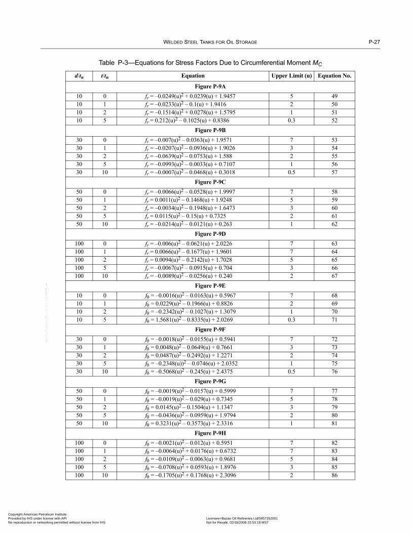
WELDED STEEL TANKS FOR OIL STORAGE P-27
Copyright AmericaProvided by IHS uNo reproduction o
Table P-3—Equations for Stress Factors Due to Circumferential Moment MC
d/tn t/tn Equation Upper Limit (u) Equation No.
Figure P-9A10 0 fr = –0.0249(u)2 + 0.0239(u) + 1.9457 5 4910 1 fr = –0.0233(u)2 – 0.1(u) + 1.9416 2 5010 2 fr = –0.1514(u)2 + 0.0278(u) + 1.5795 1 5110 5 fr = 0.212(u)2 – 0.1025(u) + 0.8386 0.3 52
Figure P-9B30 0 fr = –0.007(u)2 – 0.0363(u) + 1.9571 7 5330 1 fr = –0.0207(u)2 – 0.0936(u) + 1.9026 3 5430 2 fr = –0.0639(u)2 – 0.0753(u) + 1.588 2 5530 5 fr = –0.0993(u)2 – 0.0033(u) + 0.7107 1 5630 10 fr = –0.0007(u)2 – 0.0468(u) + 0.3018 0.5 57
Figure P-9C50 0 fr = –0.0066(u)2 – 0.0528(u) + 1.9997 7 5850 1 fr = 0.0011(u)2 – 0.1468(u) + 1.9248 5 5950 2 fr = –0.0034(u)2 – 0.1948(u) + 1.6473 3 6050 5 fr = 0.0115(u)2 – 0.15(u) + 0.7325 2 6150 10 fr = –0.0214(u)2 – 0.0121(u) + 0.263 1 62
Figure P-9D100 0 fr = –0.006(u)2 – 0.0621(u) + 2.0226 7 63100 1 fr = 0.0066(u)2 – 0.1677(u) + 1.9601 7 64100 2 fr = 0.0094(u)2 – 0.2142(u) + 1.7028 5 65100 5 fr = –0.0067(u)2 – 0.0915(u) + 0.704 3 66100 10 fr = –0.0089(u)2 – 0.0256(u) + 0.240 2 67
Figure P-9E10 0 fθ = –0.0016(u)2 – 0.0163(u) + 0.5967 7 6810 1 fθ = 0.0229(u)2 – 0.1966(u) + 0.8826 2 6910 2 fθ = –0.2342(u)2 – 0.1027(u) + 1.3079 1 7010 5 fθ = 1.5681(u)2 – 0.8335(u) + 2.0269 0.3 71
Figure P-9F30 0 fθ = –0.0018(u)2 – 0.0155(u) + 0.5941 7 7230 1 fθ = 0.0048(u)2 – 0.0649(u) + 0.7661 3 7330 2 fθ = 0.0487(u)2 – 0.2492(u) + 1.2271 2 7430 5 fθ = –0.2348(u))2 – 0.0746(u) + 2.0352 1 7530 10 fθ = –0.5068(u)2 – 0.245(u) + 2.4375 0.5 76
Figure P-9G50 0 fθ = –0.0019(u)2 – 0.0157(u) + 0.5999 7 7750 1 fθ = –0.0019(u)2 – 0.029(u) + 0.7345 5 7850 2 fθ = 0.0145(u)2 – 0.1504(u) + 1.1347 3 7950 5 fθ = –0.0436(u)2 – 0.0959(u) + 1.9794 2 8050 10 fθ = 0.3231(u)2 – 0.3573(u) + 2.3316 1 81
Figure P-9H100 0 fθ = –0.0021(u)2 – 0.012(u) + 0.5951 7 82100 1 fθ = –0.0064(u)2 + 0.0176(u) + 0.6732 7 83100 2 fθ = –0.0109(u)2 – 0.0063(u) + 0.9681 5 84100 5 fθ = –0.0708(u)2 + 0.0593(u) + 1.8976 3 85100 10 fθ = –0.1705(u)2 + 0.1768(u) + 2.3096 2 86
--``,,,,,,`,,`,`,`,``,,````,,``-`-`,,`,,`,`,,`---
n Petroleum Institute nder license with API Licensee=Bazan Oil Refineries Ltd/5957352001
Not for Resale, 02/18/2008 23:53:18 MSTr networking permitted without license from IHS
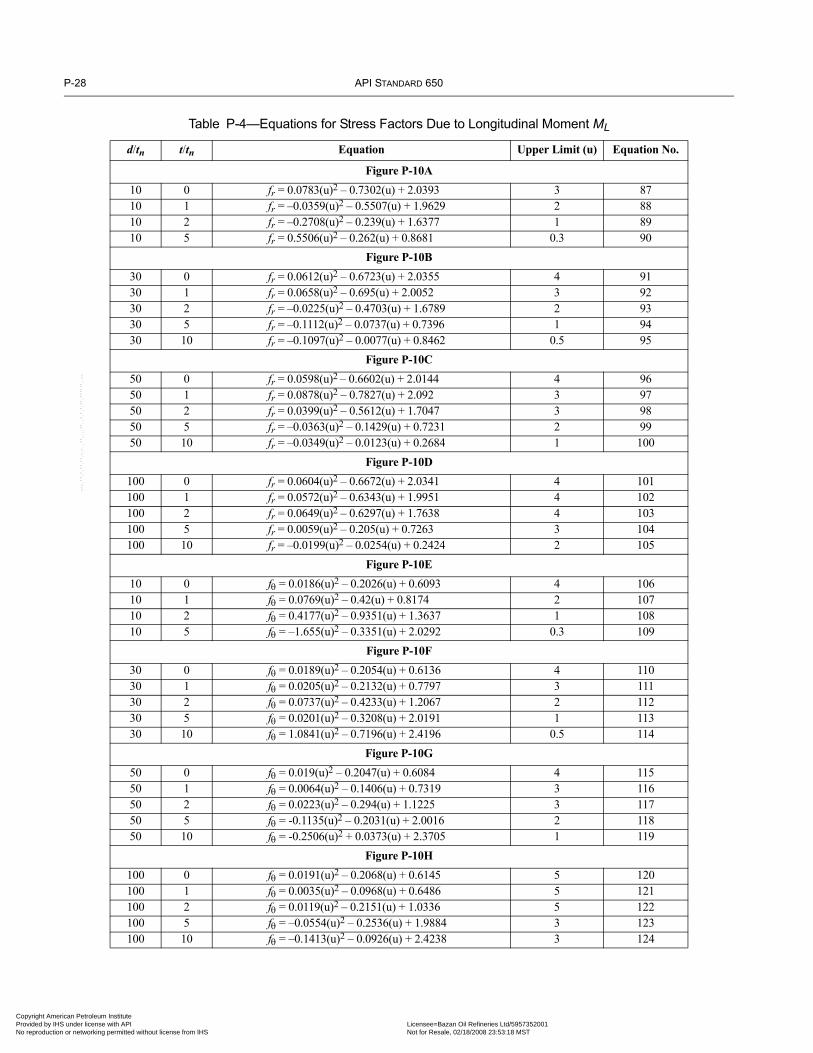
P-28 API STANDARD 650
Copyright AmProvided by No reproduc
Table P-4—Equations for Stress Factors Due to Longitudinal Moment ML
d/tn t/tn Equation Upper Limit (u) Equation No.
Figure P-10A10 0 fr = 0.0783(u)2 – 0.7302(u) + 2.0393 3 8710 1 fr = –0.0359(u)2 – 0.5507(u) + 1.9629 2 8810 2 fr = –0.2708(u)2 – 0.239(u) + 1.6377 1 8910 5 fr = 0.5506(u)2 – 0.262(u) + 0.8681 0.3 90
Figure P-10B30 0 fr = 0.0612(u)2 – 0.6723(u) + 2.0355 4 9130 1 fr = 0.0658(u)2 – 0.695(u) + 2.0052 3 9230 2 fr = –0.0225(u)2 – 0.4703(u) + 1.6789 2 9330 5 fr = –0.1112(u)2 – 0.0737(u) + 0.7396 1 9430 10 fr = –0.1097(u)2 – 0.0077(u) + 0.8462 0.5 95
Figure P-10C50 0 fr = 0.0598(u)2 – 0.6602(u) + 2.0144 4 9650 1 fr = 0.0878(u)2 – 0.7827(u) + 2.092 3 9750 2 fr = 0.0399(u)2 – 0.5612(u) + 1.7047 3 9850 5 fr = –0.0363(u)2 – 0.1429(u) + 0.7231 2 9950 10 fr = –0.0349(u)2 – 0.0123(u) + 0.2684 1 100
Figure P-10D100 0 fr = 0.0604(u)2 – 0.6672(u) + 2.0341 4 101100 1 fr = 0.0572(u)2 – 0.6343(u) + 1.9951 4 102100 2 fr = 0.0649(u)2 – 0.6297(u) + 1.7638 4 103100 5 fr = 0.0059(u)2 – 0.205(u) + 0.7263 3 104100 10 fr = –0.0199(u)2 – 0.0254(u) + 0.2424 2 105
Figure P-10E10 0 fθ = 0.0186(u)2 – 0.2026(u) + 0.6093 4 10610 1 fθ = 0.0769(u)2 – 0.42(u) + 0.8174 2 10710 2 fθ = 0.4177(u)2 – 0.9351(u) + 1.3637 1 10810 5 fθ = –1.655(u)2 – 0.3351(u) + 2.0292 0.3 109
Figure P-10F30 0 fθ = 0.0189(u)2 – 0.2054(u) + 0.6136 4 11030 1 fθ = 0.0205(u)2 – 0.2132(u) + 0.7797 3 11130 2 fθ = 0.0737(u)2 – 0.4233(u) + 1.2067 2 11230 5 fθ = 0.0201(u)2 – 0.3208(u) + 2.0191 1 11330 10 fθ = 1.0841(u)2 – 0.7196(u) + 2.4196 0.5 114
Figure P-10G50 0 fθ = 0.019(u)2 – 0.2047(u) + 0.6084 4 11550 1 fθ = 0.0064(u)2 – 0.1406(u) + 0.7319 3 11650 2 fθ = 0.0223(u)2 – 0.294(u) + 1.1225 3 11750 5 fθ = -0.1135(u)2 – 0.2031(u) + 2.0016 2 11850 10 fθ = -0.2506(u)2 + 0.0373(u) + 2.3705 1 119
Figure P-10H100 0 fθ = 0.0191(u)2 – 0.2068(u) + 0.6145 5 120100 1 fθ = 0.0035(u)2 – 0.0968(u) + 0.6486 5 121100 2 fθ = 0.0119(u)2 – 0.2151(u) + 1.0336 5 122100 5 fθ = –0.0554(u)2 – 0.2536(u) + 1.9884 3 123100 10 fθ = –0.1413(u)2 – 0.0926(u) + 2.4238 3 124
--``,,,,,,`,,`,`,`,``,,````,,``-`-`,,`,,`,`,,`---
erican Petroleum Institute IHS under license with API Licensee=Bazan Oil Refineries Ltd/5957352001
Not for Resale, 02/18/2008 23:53:18 MSTtion or networking permitted without license from IHS

WELDED STEEL TANKS FOR OIL STORAGE P-29
Copyright AmericaProvided by IHS uNo reproduction o
P.3.10.2 Solution
P.3.10.2.1 Establish the values for t, u, d/tn, B, h, and z from the data provided. To determine the stresses at the junction of thenozzle and the shell, the shell and the reinforcing pad thickness are combined, hence:
In SI Units:
t = ts + tr= 12.7 mm + 12.7 mm = 25.4 mm
u = (d/D) × (D/t)0.5
= (457/9144) × (9144/25.4)0.5
= 0.95
d/tn = 457/12.7= 36
B = 2 × (D × t)0.5
= 2 × (9144 × 25.4)0.5
= 964 mm
h = L/B= 476/964= 0.49
z = 0.67 from Figure P-11
t/tn = 25.4/12.7= 2
In US Customary units:
t = ts + tr= 0.5 in. + 0.5 in. = 1.0 in.
u = [18/(30 × 12)] × [(30 × 12)/1]0.5
= 0.95
d/tn = 18/0.5= 36
B = 2 × (30 × 12 × 1)0.5
= 38 in.
h = 18.75/38= 0.49
z = 0.67 from Figure P-11
t/tn = 1/0.5= 2
P.3.10.2.2 Calculate the stresses.
In SI Units:
The charts and equations list values for d/tn of 30 and 50. To derive the stress factor values for d/tn = 36 one must interpolatebetween the presented values.Stress factors are provided in Table P-5.
--``,,,,,,`,,`,`,`,``,,````,,``-`-`,,`,,`,`,,`---
n Petroleum Institute nder license with API Licensee=Bazan Oil Refineries Ltd/5957352001
Not for Resale, 02/18/2008 23:53:18 MSTr networking permitted without license from IHS

P-30 API STANDARD 650
Copyright AmProvided by No reproduc
Stress due to FR
σr = (FR /t2) × fr= (77843/25.42) × 0.968= 116.8 MPa
σθ = (FR /t2) × fθ= (77843/25.42) × 0.765= 92.3 MPa
Stress due to Mc
σr = (Mc /d × t2) × fr= [(8.5 × 10⁶)/(457 × 25.42)] × 1.46= 42 MPa
σθ = (Mc /d × t2) × fθ= [(8.5 × 10⁶)/(457 × 25.42)] × 1.03= 29.7 MPa
Stress due to ML
σr = (ML/d × t2) × fr= [(11.3 × 10⁶)/(457x 25.42)] × 1.2= 46 MPa
σθ = (ML/d × t2) × fθ= [(11.3 × 10⁶)/(457 × 25.42)] × 0.88= 33.7 MPa
Shear stressτMT = 2 × (MT)/(π × d2t)
= 2 × (5.6 × 106)/(π × 4572 × 25.4)= 0.67 MPa
τVC = 0
τVL = 2 × (VL)/(π × d × t)= (2 × 44500)/(π × 457 × 25.4)= 2.44 MPa
τtotal = τMT + τVC + τVL= 0.67 + 0 + 2.44= 3.11 MPa
Table P-5—Stress Factors
Load Stress Factor Figure Equation
FR fr = 0.884 P-8b & P-8c 17 & 22
FR fθ = 0.765 P-8f & P-8g 36 & 41
MC fr = 1.46 P-9b & P-9c 55 & 60
MC fθ = 1.03 P-9f & P-9g 70 & 74
ML fr = 1.2 P-10b & P-10c 93 & 98
ML fθ = 0.88 P-10f & P-10g 112 & 117
--``,,,,,,`,,`,`,`,``,,````,,``-`-`,,`,,`,`,,`---
erican Petroleum Institute IHS under license with API Licensee=Bazan Oil Refineries Ltd/5957352001
Not for Resale, 02/18/2008 23:53:18 MSTtion or networking permitted without license from IHS

WELDED STEEL TANKS FOR OIL STORAGE P-31
Copyright AmericaProvided by IHS uNo reproduction o
--``,,,,,,`,,`,`,`,``,,````,,``-`-`,,`,,`,`,,`---
Combine the stresses.Smax = largest absolute magnitude of
= 0.5z × [(σr + σθ) ± {(σr – σθ)2 + 4τ2}0.5]
Combine the stress values from FR and MC.σr = 106.7 + 42
= 148.7 MPa
σθ = 92.3 + 29.7= 122 MPa
Combine the stress values from FR and ML.σr = 106.7 + 46
= 152.7 MPa
σθ = 92.3 + 33.7= 126 MPa
The maximum stress is a combination of the radial thrust and the longitudinal moment.Smax = 0.5 × 0.67 × [(162.8 + 126) ± {(152.7 – 126)2 + 4 × 3.112}0.5]
= 102.5 MPa
Sall = 1.0 × Sd (mechanical load)= 1.5 × Sd (thermal load)= 1.5 × 160 (thermal load)= 240 MPa
Sall > Smax
In US Customary units:
The charts and equations list values for d/tn of 30 and 50. To derive the stress factor values for d/tn = 36 one must interpolatebetween the presented values.
Using the stress factors from Table P-5:
Stresses due to FR
σr = (FR /t2) × fr= (17,500/12) × 0.884= 15,470 lbf/in.2
σθ = (FR /t2) × fθ= (17,500/12) × 0.765= 13,388 lbf/in.2
Stresses due to MC
σr = (MC /d × t2) × fr= {(75,000)/(18 × 12)} × 1.46= 6083 lbf/in.2
n Petroleum Institute nder license with API Licensee=Bazan Oil Refineries Ltd/5957352001
Not for Resale, 02/18/2008 23:53:18 MSTr networking permitted without license from IHS

P-32 API STANDARD 650
Copyright AmProvided by No reproduc
σθ = (Mc /d × t2) × fθ= {(75,000)/(18 × 12)} × 1.03= 4292 lbf/in.2
Stresses due to ML
σr = (ML/d × t2) × fr= {(100,000)/(18 × 12)} × 1.2= 6670 lbf/in.2
σθ = (ML/d × t2) × fθ= {(100,000)/(18 × 12)} × 0.88= 4890 lbf/in.2
Shear stressτMT = 2 × (MT)/(π × d2t)
= 2 × (50,000)/(π × 182 × 1)= 98 lbf/in.2
τVC = 0
τVL = 2 × (VL)/(π × d × t)= 2 × (10,000)/(π × 18 × 1)= 354 lbf/in.2
τtot = τMT + τVC + τVL= 98 + 0 + 354= 452 lbf/in.2
Combine the stresses.Smax = largest absolute magnitude of
= 0.5z·[(σr + σθ) ± {(σr – σθ)2 + 4τ2}0.5]
Combine the stress values from FR and MC.σr = 15,470 + 6083
= 21,553 lbf/in.2
σθ = 13,388 + 4292
= 17,680 lbf/in.2
Combine stress values from FR and ML.σr = 15,470 + 6670
= 22,140 lbf/in.2
σθ = 13,388 + 4890
= 18,278 lbf/in.2
The maximum stress is a combination of the radial thrust and the longitudinal moment.Smax = 0.5 × 0.67 × [(22,140 + 18,278) ± {(22,140 – 18,278)2 + 4 × 4522}0.5]
= 14,869 lbf/in.2
erican Petroleum Institute IHS under license with API Licensee=Bazan Oil Refineries Ltd/5957352001
Not for Resale, 02/18/2008 23:53:18 MSTtion or networking permitted without license from IHS
--``,,,,,,`,,`,`,`,``,,````,,``-`-`,,`,,`,`,,`---

WELDED STEEL TANKS FOR OIL STORAGE P-33
Copyright AmericaProvided by IHS uNo reproduction o
Sall = 1.0 × Sd (mechanical load)= 1.5 × Sd (thermal load)= 1.5 × 23,200 (thermal load)= 34,800 lbf/in.2
Sall > Smax
P.3.10.3 Conclusion
Since the allowable stress is greater than the maximum stress, the attached piping system is acceptable.
P.3.11 SAMPLE PROBLEM NO. 2
P.3.11.1 Data
Calculate the stresses for a tank nozzle using the following data.
Tank material: A 36M (A 36), Sd = 160 MPa (23,200 lbf/in.2)
D = 36,500 mm (120 ft)
t = 12.7 mm (0.5 in.)
d = 610 mm (24 in.)
tn = 12.7 mm (0.5 in.)
L = 630 mm (24.75 in.)
No reinforcing pad is providedThe mechanical loads from the attached piping system are as follows:
FR = 87,700 N (20,000 lbs)
MC = 11 × 106 N-mm (100,000 in.-lbs)
ML = 13.3 × 10⁶ N-mm (120,000 in.-lbs)
MT = VC = VL = 0
P.3.11.2 Solution
P.3.11.2.1 Establish the values for t, u, d/tn, B, and h from the data provided.
In SI units:u = (d/D) × (D/t)0.5
u = (610/36,500) × (36,500/12.7)0.5
= 0.9
d/tn = 610/12.7= 48.03
Use d/tn = 50
t/tn = 12.7/12.7= 1
B = 2 × (Dt)0.5
B = 2(36,500 × 12.7)0.5
--``,,,,,,`,,`,`,`,``,,````,,``-`-`,,`,,`,`,,`---
n Petroleum Institute nder license with API Licensee=Bazan Oil Refineries Ltd/5957352001
Not for Resale, 02/18/2008 23:53:18 MSTr networking permitted without license from IHS

P-34 API STANDARD 650
Copyright AmProvided by No reproduc
= 1362 mm
h = L/B
h = 630/1362= 0.46
In US Customary units:
u = (d/D) × (D/t)0.5
u = (24/[120 × 12]) × (120 × 12/0.5)0.5
= 0.9
d/tn = 24/0.5= 48
Use d/tn = 50
t/tn = 0.5/0.5= 1
B = 2 × (Dt)0.5
= 2 × (120 × 12 × 0.5)0.5
= 53.67 in.
h = L/B= 24.75/53.67= 0.46
P.3.11.2.2 Calculate the stresses.
In SI units:
Stress factors are provided in Table P-6.
Stress due to FR,σr = (FR/t2) × frσr = (87,700/12.72) × 1.72
= 935 N/mm2
σθ = 87,700 × 1.15/12.72
= 625 MPa
Table P-6—Stress Factors for Sample Problem No. 1
Load Stress Factor Figure Equation
FR fr = 1.72 P-8c 21
FR fθ = 1.15 P-8g 40
MC fr = 1.8 P-9c 59
MC fθ = 0.68 P-9g 78
ML fr = 1.43 P-10c 97
ML fθ = 0.62 P-10g 116
erican Petroleum Institute IHS under license with API Licensee=Bazan Oil Refineries Ltd/5957352001
Not for Resale, 02/18/2008 23:53:18 MSTtion or networking permitted without license from IHS
--``,,,,,,`,,`,`,`,``,,````,,``-`-`,,`,,`,`,,`---

WELDED STEEL TANKS FOR OIL STORAGE P-35
Copyright AmericaProvided by IHS uNo reproduction o
--``,,,,,,`,,`,`,`,``,,````,,``-`-`,,`,,`,`,,`---
Stress due to MC,σr = (MC/d × t2) × frσr = (11 × 106)/(610 × 12.72)1.8
= 201 MPa
σθ = (11 × 106)/(610 × 12.72) x 0.68 = 76 MPa
Stress due to ML,σr = (ML/d × t2) × frσr = (13.3 × 10⁶)/(610 × 12.72) × 1.2
= 193.3 MPa
σθ = (ML/d × t2) × fθσθ = (13.3 × 10⁶)/(610 × 12.72) × 0.62
= 83.81 MPa
Calculate the stress intensities.S = 0.5 × [(σr + σθ) ± {(σr – σθ)2 + 4τ2}0.5]
Radial thrust and circular moment (bending)σr = σrFR + σrCσr = 935 + 201
= 1136 MPa
Radial thrust and circular moment (membrane)σθ = σθFR + σθCσθ = 625 + 76
= 701 MPa
Radial thrust and longitudinal moment (bending)σr = σrFR + σrLσr = 935 + 193.3
= 1128.3 MPa
Radial thrust and longitudinal moment (membrane)σθ = σθFR + σθLσθ = 625 + 83.81
= 708.81 MPa
Smax = 0.5 × [(σrmax + σθmax) ± {(σrmax – σθmax)2 + 4τmax2}0.5]
Smax = 0.5 × [(1136 + 708.81) ± {(1136 – 708.81)2 + 4 × 02}0.5]= 1136 MPa
From Figure P-8 with a height factor of h = 0.46, the stress reduction factor z = 0.64.
Multiply Smax with the stress reduction factor.S = Smax × zS = 1136 × 0.64
= 727 MPa
n Petroleum Institute nder license with API Licensee=Bazan Oil Refineries Ltd/5957352001
Not for Resale, 02/18/2008 23:53:18 MSTr networking permitted without license from IHS

P-36 API STANDARD 650
Copyright AmProvided by No reproduc
--``,,,,,,`,,`,`,`,``,,````,,``-`-`,,`,,`,`,,`---
Compare S with the allowable stress.Sd = 160 MPa (see Table 5-2)
For thermal loads:Sall = 1.5 × Sd
Sall = 1.5 × 160= 240 MPa
S > Sall
727 MPa > 240 MPa
In US Customary units:
Using the stress factors from Table P-6,
Stress due to FR,σr = (FR/t2) × fr
= (20,000/0.52) × 1.72= 13,7600 lbf/in.2
σθ = (FR/t2) × fθ= 20,000 × 1.15/0.52
= 92,000 lbf/in.2
Stress due to MC,σr = (MC/d × t2) × fr
= (100,000)/(24 × 0.52) × 1.8= 30,000 lbf/in.2
σθ = (MC/d × t2) × fθ= 10 × 106/(24 × 0.52) × 0.68= 11,333 lbf/in.2
Stress due to ML,σr = (ML/d × t2) × fr
= (120,000)/(24 × 0.52) × 1.43= 28,600 lbf/in.2
σθ = (ML /d × t2) × fθ= (120,000)/(24 × 0.52) × 0.62= 12,400 lbf/in.2
Calculate the stress intensities.S = 0.5 × [(σr + σθ) ± {(σr – σθ)2 + 4τ2}0.5]
Radial thrust and circular moment (bending)σr = σrFR + σrC
= 137,600 + 30,000= 167,600 lbf/in.2
erican Petroleum Institute IHS under license with API Licensee=Bazan Oil Refineries Ltd/5957352001
Not for Resale, 02/18/2008 23:53:18 MSTtion or networking permitted without license from IHS

WELDED STEEL TANKS FOR OIL STORAGE P-37
Copyright AmericaProvided by IHS uNo reproduction o
Radial thrust and circular moment (membrane)σθ = σθFR + σθC
= 92,000 + 11,333= 103,333 lbf/in.2
Radial thrust and longitudinal moment (bending)σr = σrFR + σrL
= 137,600 + 28,600= 166,200 lbf/in.2
Radial thrust and longitudinal moment (membrane)σθ = σθFR + σθL
= 92,000 + 12,400= 104,400 lbf/in.2
Smax = 0.5 × [(σrmax + σθmax) ± {(σrmax – σθmax)2 + 4τmax2}0.5]
= 0.5 × [(167,600+104,400) ± {(167,600 – 104,400)2 + 4 × 02}0.5]= 167,600 lbf/in.2
From Figure P-8, with a height factor of h = 0.46, the stress reduction factor Z = 0.64.
Multiplying Smax with the stress reduction factor:S = Smax × Z
= 167,600 × 0.64= 107,264 lbf/in.2
Compare S with the allowable stressSd = 23,200 lbf/in.2 (see Table 5-2)
For thermal loadsSall = 1.5 × Sd
= 1.5 × 23,200= 34,800 lbf/in.2
S > Sall
107,264 lbf/in.2 > 34,800 lbf/in.2
P.3.11.2.3 Conclusion
Since the actual stress exceeds the allowable stress, S > Sall, a reinforcing plate shall be attached.
P.3.11.2.4 Reinforcing Plate Calculations
Refer to Table 5-6 for the size of reinforcing pad.
In SI units:
Do = 1525 mmtr = 12.7 mm
To calculate the stress at the junction of the nozzle to the shell, the combined thickness of the shell and reinforcing plate is used inthe calculations. In this case:
n Petroleum Institute nder license with API Licensee=Bazan Oil Refineries Ltd/5957352001
Not for Resale, 02/18/2008 23:53:18 MSTr networking permitted without license from IHS
--``,,,,,,`,,`,`,`,``,,````,,``-`-`,,`,,`,`,,`---

P-38 API STANDARD 650
Copyright AmProvided by No reproduc
t = 12.7 + 12.7= 25.4 mm
u = (d/D) × (D/t)0.5
u = (610/36,500) × (36,500/25.4)0.5
= 0.63
d/tn = 610/12.7= 48
Use d/tn = 50
t/tn = 25.4/12.7= 2
B = 2 × (Dt)0.5
B = 2 × (36,500 × 25.4)0.5
= 1926 mm
h = L/Bh = 630/1926
= 0.327
z = 0.55
Calculated StressesFR: σr = 177 MPaFR: σθ = 136 MPa
MC: σr = 42 MPaMC: σθ = 29 MPaML: σr = 46 MPaML: σθ = 30 MPa
Calculate stress intensityFR & MC: σr = 177 + 42
σr = 219 MPaFR & MC: σθ = 136 + 29
σθ = 165 MPaFR & ML: σr = 177 + 46
σr = 223 MPaFR & ML: σθ = 136 + 30
σθ = 166 MPa
Smax = 0.5 × [(σrmax + σθmax) ± {(σrmax – σθmax)2 + 4τmax2}0.5]
Smax = 0.5 × [(223 + 166) ± {(223 – 166)2 + 4 × 02}0.5]= 223 MPa
S = Smax × zS = 223 × 0.55
= 123 MPa
S > Sall
223 MPa > 123 MPa
erican Petroleum Institute IHS under license with API Licensee=Bazan Oil Refineries Ltd/5957352001
Not for Resale, 02/18/2008 23:53:18 MSTtion or networking permitted without license from IHS
--``,,,,,,`,,`,`,`,``,,````,,``-`-`,,`,,`,`,,`---

WELDED STEEL TANKS FOR OIL STORAGE P-39
Copyright AmericaProvided by IHS uNo reproduction o
In US Customary units:
Do = 60 in.tr = 0.5 in.
To calculate the stress at the junction of the nozzle to the shell, the combined thickness of the shell and reinforcing plate is used inthe calculations. In this case:
t = 0.5 + 0.5= 1.0 in.
u = (d/D) × (D/t)0.5
u = [24/(120 x 12)] × [(120 × 12)/1.0]0.5
= 0.63
d/tn = 24/0.5
= 48Use d/tn = 50
t/tn = 1.0/0.5
= 2
B = 2 × (Dt)0.5
B = 2 × (120 × 12 × 1.0)0.5
= 76 in.
h = L/Bh = 24.75/76
= 0.326
z = 0.55
Using the stress reduction factors in Table P-7, the stresses can be calculated as follows:FR = 26,000 lbf/in.2
FR = 20,000 lbf/in.2
MC = 6250 lbf/in.
MC = 4375 lbf/in.2
ML = 6750 lbf/in.2
ML = 4500 lbf/in.2
Table P-7—Stress Factors for the Reinforcing Plate
Load Stress Factor Figure Equation
FR fr = 1.3 P-8C 22
FR fθ = 1.0 P-8G 41
MC fr = 1.5 P-9C 60
MC fθ = 1.05 P-9G 79
ML fr = 1.35 P-10C 98
ML fθ = 0.9 P-10G 117
--``,,,,,,`,,`,`,`,``,,````,,``-`-`,,`,,`,`,,`---
n Petroleum Institute nder license with API Licensee=Bazan Oil Refineries Ltd/5957352001
Not for Resale, 02/18/2008 23:53:18 MSTr networking permitted without license from IHS

P-40 API STANDARD 650
Copyright AmProvided by No reproduc
Calculate stress intensities.FR & MC = 26,000 + 6250
= 32,250 lbf/in.2
FR & MC = 20,000 + 4375
= 24,375 lbf/in.2
FR & ML = 26,000 + 6750
= 32,750 lbf/in.2
FR & ML = 20,000 + 4500
= 24,500 lbf/in.2
Smax = 0.5 × [(σrmax + σθmax) ± {(σrmax – σθmax)2 + 4τmax2}0.5]
Smax = 0.5[(32,750 + 24,500) ± {(32,750 – 24,500)2 + 4 × 02}0.5]
= 32,750 lbf/in.2
S = Smax × zS = 32,750 × 0.55
= 18,013 lbf/in.2
S > Sall
32,750 lbf/in.2 > 18,013 lbf/in.2
P.3.11.2.5 Conclusion
The attached piping system with the reinforcing plate is acceptable for the tank since the actual stress is less than the maximumstress.
P.3.12 SAMPLE PROBLEM NO. 3
This sample problem uses the alternative method on the data presented in the sample problem in P.9. The calculated limit loadsfrom in P.2.9 are assumed to be from thermal loads. The stresses are calculated using the equations from Tables P-2 through P-4.
P.3.12.1 Data
Tank diameter D = 80 m (260 ft or 3120 in)
Tank shell thickness t = 34 mm (1.33 in)
Nozzle outside diameter d = 610 mm (24 in)
Nozzle neck thickness (assumed) tn = 31 mm (1.218 in)
Nozzle location from bottom L = 630 mm (24.75 in)
Design stress Sd = 160 MPa (23,200 lbf/in.2)
Using the limit loads from P.9.3:
FR = 320,000 N (74800 lbs)
MC = 550 × 106 N⋅mm (4.95 × 10⁶ in⋅lbs)
ML = 195 × 106 N⋅mm (1.74 × 10⁶ in⋅lbs)
MT = VC = VL = 0
erican Petroleum Institute IHS under license with API Licensee=Bazan Oil Refineries Ltd/5957352001
Not for Resale, 02/18/2008 23:53:18 MSTtion or networking permitted without license from IHS
--``,,,,,,`,,`,`,`,``,,````,,``-`-`,,`,,`,`,,`---

WELDED STEEL TANKS FOR OIL STORAGE P-41
Copyright AmericaProvided by IHS uNo reproduction o
--``,,,,,,`,,`,`,`,``,,````,,``-`-`,,`,,`,`,,`---
P.3.12.2 Solution
P.3.12.2.1 Establish the values for t, u, d/tn, and t/tn from the data provided.
In SI units:
u = (d/D) × (D/t)0.5
u = (610/80,000) × (80,000/34)0.5
= 0.37
d/tn = 610/31= 20
t/tn = 34/31= 1.096
Use t/tn = 1
In US Customary units:u = (d/D) × (D/t)0.5
u = (24/3120) × (3120/1.33)0.5
= 0.37
d/tn = 24/1.218= 20
t/tn = 1.33/1.218= 1.092
Use t/tn = 1
P.3.12.2.2 To calculate the stress factors, interpolation is required between d/t = 10 and 30 to arrive at the values for d/t = 18
FR fT for d/tn = 10 and t/tn = 1 (12)fr = –0.9384 × ln(u) + 1.2638
= –0.9384 × ln(0.37) + 1.2638= 2.197
fT for d/tn = 30 and t/tn = 1 (16)fr = –0.9074 × ln(u) + 1.3398
= –0.9074 × ln(0.37) + 1.3398= 2.242
fT for d/tn = 20 and t/tn = 1fr = 0.5(2.197 + 2.242)
= 2.219
FR fθ for d/tn = 20 and t/tn = 1 (31 and 35)fθ = 0.5{(–0.3427 × ln(u) + 0.5338) + (–0.344 × ln(u) + 0.6352)}
= 0.9259
MC fr for d/tn = 20 and t/tn = 1 (50 and 54)
n Petroleum Institute nder license with API Licensee=Bazan Oil Refineries Ltd/5957352001
Not for Resale, 02/18/2008 23:53:18 MSTr networking permitted without license from IHS

P-42 API STANDARD 650
Copyright AmProvided by No reproduc
fr = 0.5{(–0.0233 × u2 – 0.1 x u + 1.9416) + (–0.0207 × u2 – 0.0936 x u + 1.9026)}= 1.883
fθ = 0.5{(0.0229 × u2 – 0.1966 × u + 0.8826) + (0.0048 × u2 – 0.0649 × u + 0.7661)} (69 and 73)= 1.322
ML fθ = 0.5{(0.0769 × u2 – 0.42 × u + 0.8174) + (0.0205 × u2 – 0.2132 × u + 0.7797)} (107 and 111)= 0.688
fr = 0.5{(–0.0359 × u2 – 0.5507 × u + 1.9629) + (0.0658 × u2 – 0.695 × u + 2.0052)} (88 and 92)= 1.7556
P.3.12.2.3 Calculate the stresses.
In SI units:
Stress due to FR,σr = (FR/t2) × frσr = (328,000/342) × 2.219
= 629 MPa
σθ = (FR/t2) × fθσθ = 328,000 × 0.9259/342
= 263 MPa
Stress due to MC,σr = (MC/d x t2) × frσr = (550 × 106)/(610 × 342) x 1.883
= 1469 MPa
σθ = (MC/d × t2) × fθσθ = (550 × 106)/(610 × 342) × 1.322
= 1031 MPa
Stress due to ML,σr = (ML/d × t2) × frσr = (195 × 106)/(610 × 342) × 1.7556
= 485 MPa
σθ = (ML/d × t2) × fθσθ = (195 × 106)/(610 × 342) × 0.688
= 190 MPa
In US Customary units:
Stress due to FR,σr = (FR/t2) × fr
= (74,800/1.332) × 2.219= 93,833 lbf/in.2
--``,,,,,,`,,`,`,`,``,,````,,``-`-`,,`,,`,`,,`---
erican Petroleum Institute IHS under license with API Licensee=Bazan Oil Refineries Ltd/5957352001
Not for Resale, 02/18/2008 23:53:18 MSTtion or networking permitted without license from IHS

WELDED STEEL TANKS FOR OIL STORAGE P-43
Copyright AmericaProvided by IHS uNo reproduction o
σθ = (FR/t2) × fθ
= 74,800 × 0.9259/1.332
= 39,153 lbf/in.2
Stress due to MC,
σr = (MC/d × t2) × fr
= (4.95 × 10⁶)/(24 × 1.332) × 1.883= 199,594 MPa
σθ = (MC /d × t2) × fθ
= (4.95 × 10⁶)/(24 × 1.332) × 1.322
= 140,129 lbf/in.2
Stress due to ML,
σr = (ML/d × t2) x fr
= (1.74 × 10⁶)/(24 × 1.332) × 1.7556
= 71,955 lbf/in.2
σθ = (ML/d × t2) × fθ
= (1.74 × 10⁶)/(24 × 1.332) × 0.688
= 28,198 lbf/in.2
P.3.12.2.4 Calculate the stress reduction factors.
In SI units:
B = 2 × (D × t)0.5
B = 2 × (80,000 × 34)0.5
= 3298 mm
h = L/Bh = 630/3298
= 0.19
In US Customary units:
B = 2 × (D × t)0.5
= 2 × (3120 × 1.33)0.5
= 129 in.
h = L/B= 24.75/129= 0.19
P.3.12.2.5 Calculate the stress intensity.
S = 0.5 × z × [(σr + σθ) ± {(σr – σθ)2 + 4τ2}0.5]
n Petroleum Institute nder license with API Licensee=Bazan Oil Refineries Ltd/5957352001
Not for Resale, 02/18/2008 23:53:18 MSTr networking permitted without license from IHS
--``,,,,,,`,,`,`,`,``,,````,,``-`-`,,`,,`,`,,`---

P-44 API STANDARD 650
Copyright AmProvided by No reproduc
Where z = 0.47 from Figure P-11, and Smax is from the combination of FR and MC.
In SI units:Smax = 0.5 × 0.47 × [(629 + 263) ± {(629 – 263)2 + 4⋅02}0.5]
= 296 MPa
In US Customary units:Smax = 0.5 × 0.47 × [(93833 + 39153) ± {(93833 – 39153)2 + 4⋅02}0.5]
= 44,102 lbf/in.2
For this sample problem it is assumed that the limit loads include the liquid load from the tank, therefore the preceding stresses aretotal stresses. In this case the allowable stress is:
Sall = 2.0 Sd Mechanical Load= 3.0 Sd Thermal Load
In this problem it is assumed that the loads are of thermal nature, therefore the allowable stresses are:
In SI units:
Sall = 3.0 × 160 MPa= 480 MPa
Sall > Smax
480 MPa > 296 MPa
In US Customary units:Sall = 3.0 x 23,200 lbf/in.2
= 69,600 lbf/in.2
Sall > Smax
69,600 lbf/in.2 > 44,102 lbf/in.2
P.3.12.3 Conclusion
Based on the assumptions made, this analysis indicates that the piping arrangement for example P.2.9 is acceptable.
--``,,,,,,`,,`,`,`,``,,````,,``-`-`,,`,,`,`,,`---
erican Petroleum Institute IHS under license with API Licensee=Bazan Oil Refineries Ltd/5957352001
Not for Resale, 02/18/2008 23:53:18 MSTtion or networking permitted without license from IHS
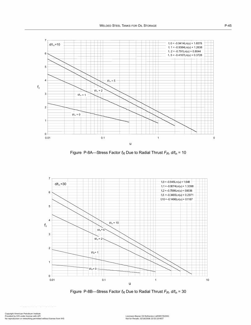
WELDED STEEL TANKS FOR OIL STORAGE P-45
Copyright AmericaProvided by IHS uNo reproduction o
--
Figure P-8A—Stress Factor fR Due to Radial Thrust FR, d/tn = 10
Figure P-8B—Stress Factor fR Due to Radial Thrust FR, d/tn = 30
0
1
2
3
4
5
6
7
0.01 0.1 1 0
u
fr
d/t n=10
t/t n = 5
t/t n = 0
t/t n = 2
t/t n = 1
fr 0 = -0.9414Ln(u) + 1.6578
fr 1 = -0.9384Ln(u) + 1.2638
f r 2 = -0.791Ln(u) + 0.8044
f r 5 = -0.4167Ln(u) + 0.3728
=2
t/t n=5
fr0 = -0.945Ln(u) + 1.648
f r1 = -0.9074Ln(u) + 1.3398
fr2 = -0.7596Ln(u) + 0.9036
fr5 = -0.3465Ln(u) + 0.2971
fr10 = -0.1496Ln(u) + 0.1187
0
1
2
3
4
5
6
7
0.01 0.1 1 10
u
fr
d/tn =30
t/tn = 10
t/tn= 5
t/t n = 2
t/tn= 1
t/tn= 0
n Petroleum Institute nder license with API Licensee=Bazan Oil Refineries Ltd/5957352001
Not for Resale, 02/18/2008 23:53:18 MSTr networking permitted without license from IHS
``,,,,,,`,,`,`,`,``,,````,,``-`-`,,`,,`,`,,`---

P-46 API STANDARD 650
Copyright AmProvided by No reproduc
Figure P-8C—Stress Factor fR Due to Radial Thrust FR, d/tn = 50
Figure P-8D—Stress Factor fR Due to Radial Thrust FR, d/tn = 100
fr0 = -0.9507Ln(u) + 1.6453
fr1 = -0.8732Ln(u) + 1.4563
fr2 = -0.7608Ln(u) + 0.9842
fr5 = -0.3333Ln(u) + 0.316
fr10 = -0.1304Ln(u)+ 0.1071
0
1
2
3
4
5
6
7
0.01 0.1 1 10u
fr
d/tn= 50
t/t n = 10
t/tn= 5
t/t n= 2
t/tn= 1
t/tn= 0
fr0 = -0.9549Ln(u)+ 1.6506
fr1 = -0.8772Ln(u)+ 1.4815
fr10 = -0.1176Ln(u) + 0.0941
fr5 = -0.3344Ln(u) + 0.33
fr2 = -0.7641Ln(u)+1.0928
0
1
2
3
4
5
6
7
0.01 0.1 1 10
u
fr
d/ tn= 100
t/t n = 10
t/t n = 5
t/t n = 2
t/t n = 1
t/t n = 0
erican Petroleum Institute IHS under license with API Licensee=Bazan Oil Refineries Ltd/5957352001
Not for Resale, 02/18/2008 23:53:18 MSTtion or networking permitted without license from IHS
--``,,,,,,`,,`,`,`,``,,````,,``-`-`,,`,,`,`,,`---

WELDED STEEL TANKS FOR OIL STORAGE P-47
Copyright AmericaProvided by IHS uNo reproduction o
Figure P-8E—Stress Factor fθ Due to Radial Thrust FR, d/tn = 10
Figure P-8F—Stress Factor fθ Due to Radial Thrust FR, d/tn = 30
f 0 = -0.2827Ln(u)+0.4845
f 1 = -0.3427Ln(u)+ 0.5338
f 2= -0.5255Ln(u)+ 0.4772
f 5 = -0.878Ln(u)+ 0.7936
0
1
2
3
4
5
6
0.01 0.1 1 10
u
f
d/tn=10
t/ tn= 10
t/ tn = 2
t/tn = 1
t/tn = 0
f 0 = -0.2833Ln(u) +0.4878
f 1 = -0.344Ln(u)+ 0.6352
f 2 =-0.4868Ln(u) +0.7312
f 5 = -0.8929Ln(u)+ 0.8883
f 10 = -1.0961Ln(u) + 1.1698
0
1
2
3
4
5
6
7
0.01 0.1 1 10
u
f
d/tn= 30
t/t n= 10
t/t n = 5
t/t n= 2
t/t n= 1
t/t n = 0
--``,,,,,,`,,`,`,`,``,,````,,``-`-`,,`,,`,`,,`---
n Petroleum Institute nder license with API Licensee=Bazan Oil Refineries Ltd/5957352001
Not for Resale, 02/18/2008 23:53:18 MSTr networking permitted without license from IHS
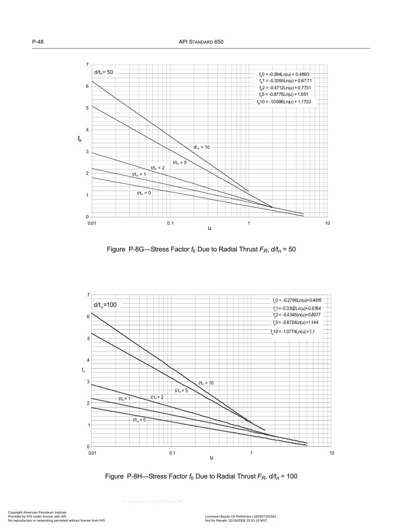
P-48 API STANDARD 650
Copyright AmProvided by No reproduc
Figure P-8G—Stress Factor fθ Due to Radial Thrust FR, d/tn = 50
Figure P-8H—Stress Factor fθ Due to Radial Thrust FR, d/tn = 100
f 0 = -0.284Ln(u) + 0.4893
f 1 = -0.3355Ln(u) + 0.6771
f 2 = -0.4712Ln(u) + 0.7731
f 5 = -0.8775Ln(u) + 1.051
f 10 = -1.0986Ln(u) + 1.1733
0
1
2
3
4
5
6
7
0.01 0.1 1 10u
f
d/tn= 50
t/t n = 10
t/tn = 5
t/tn = 2
t/tn = 1
t/tn = 0
f 0 = -0.2796Ln(u)+0.4815
f 1=-0.3302Ln(u)+0.6764
f 2= -0.4346Ln(u)+0.8077
f 5= -0.8724Ln(u)+1.144
f 10 = -1.0774Ln(u) +1.1
0
1
2
3
4
5
6
7
0.01 0.1 1 10u
f
d/tn=100
t/tn = 10
t/ tn= 5
t/ tn= 2t/tn= 1
t/tn = 0
erican Petroleum Institute IHS under license with API Licensee=Bazan Oil Refineries Ltd/5957352001
Not for Resale, 02/18/2008 23:53:18 MSTtion or networking permitted without license from IHS
--``,,,,,,`,,`,`,`,``,,````,,``-`-`,,`,,`,`,,`---

WELDED STEEL TANKS FOR OIL STORAGE P-49
Copyright AmericaProvided by IHS uNo reproduction o
Figure P-9A—Stress Factor fr Due to Circumferential Moment MC, d/tn = 10
Figure P-9B—Stress Factor fr Due to Circumferential Moment MC, d/tn = 30
fr0 = -0.0249u2 + 0.0239u+ 1.9457
fr1 = -0.0233u2 - 0.1u + 1.9416
fr2 = -0.1514u2 + 0.0278u + 1.5795
fr5 = 0.212u2 - 0.1025u + 0.8386
0
0.5
1
1.5
2
2.5
0.01 0.1 1 10
u
fr
d/tn= 10
t/tn= 0
t/tn= 1
t/tn= 2
t/tn= 5
fr0 = -0.007u2
- 0.0363u + 1.9571
fr1 = -0.0207u2- 0.0936u+1.9026
fr2 = -0.0639u2- 0.0753u + 1.588
fr5 = -0.0993u2- 0.0033u+ 0.7107
fr10 = -0.0007u2- 0.0468u + 0.3018
0
0.5
1
1.5
2
2.5
0.01 0.1 1 10
u
fr
d/t n= 3
t/tn = 0
t/ tn =1
t/tn= 2
t/ tn= 5
t/ tn =1 0
--``,,,,,,`,,`,`,`,``,,````,,``-`-`,,`,,`,`,,`---
n Petroleum Institute nder license with API Licensee=Bazan Oil Refineries Ltd/5957352001
Not for Resale, 02/18/2008 23:53:18 MSTr networking permitted without license from IHS

P-50 API STANDARD 650
Copyright AmProvided by No reproduc
--``,,,,,,`,,`,`,`,``,,````,,``-`-`,,`,,`,`,,`---
Figure P-9C—Stress Factor fr Due to Circumferential Moment MC, d/tn = 50
Figure P-9D—Stress Factor fr Due to Circumferential Moment MC, d/tn = 100
fr0 = -0.0066u2 - 0.0528u + 1.9997
fr1 = 0.0011u2 - 0.1468u + 1.9248
fr2 = -0.0034u 2 - 0.1948u + 1.6473
fr 5 = 0.0115u2 - 0.15u + 0.7325
fr10 = -0.0214u2 - 0.0121u + 0.263
0
0.5
1
1.5
2
2.5
0.01 0.1 1 10
u
fr
d/ tn= 50
t/tn = 0
t/tn = 1
t/tn = 2
t/tn = 5
t/tn =10
fr0 = -0.006u2 - 0.0621u + 2.0226
fr1 = 0.0066u2 - 0.1677u +1.9601
fr2 = 0.0094u2 - 0.2142u + 1.7028
fr5 = -0.0067u 2 - 0.0915u + 0.704
fr10= -0.0089u 2 - 0.0256u +0.24
0
0.5
1
1.5
2
2.5
0.01 0.1 1 10
u
fr
d/tn =100
t/tn= 0
t/tn= 1
t/tn= 2
t/t n= 5
t/tn=10
erican Petroleum Institute IHS under license with API Licensee=Bazan Oil Refineries Ltd/5957352001
Not for Resale, 02/18/2008 23:53:18 MSTtion or networking permitted without license from IHS

WELDED STEEL TANKS FOR OIL STORAGE P-51
Copyright AmericaProvided by IHS uNo reproduction o
Figure P-9E—Stress Factor fθ Due to Circumferential Moment MC, d/tn = 10
Figure P-9F—Stress Factor fθ Due to Circumferential Moment MC, d/tn = 30
f 0 = -0.0016u2
- 0.0163u+0.5967
f 1 = 0.0229u2 - 0.1966u+ 0.8826
f 2 = -0.2342u 2 - 0.1027u +1.3079
f 5 =1.5681u2 - 0.8335u +2.0269
0
0.5
1
1.5
2
2.5
0.01 0.1 1 10u
f
d/tn= 10
t/t n= 0
t/t n= 1
t/t n = 2
t/t n= 5
f 0 = -0.0018u 2 - 0.0155u + 0.5941
f 1 = 0.0048u2 - 0.0649u + 0.7661
f 2 = 0.0487u 2 - 0.2492u + 1.2271
f 5 = -0.2348u 2 - 0.0746u + 2.0352
f 10 = -0.5068u 2 - 0.245u+ 2.4375
0
0.5
1
1.5
2
2.5
3
0.01 0.1 1 10
u
f
d/tn= 30
t/t n= 0
t/t n= 1
t/t n= 2
t/t n= 5
t/t n =10
--``,,,,,,`,,`,`,`,``,,````,,``-`-`,,`,,`,`,,`---
n Petroleum Institute nder license with API Licensee=Bazan Oil Refineries Ltd/5957352001
Not for Resale, 02/18/2008 23:53:18 MSTr networking permitted without license from IHS

P-52 API STANDARD 650
Copyright AmProvided by No reproduc
Figure P-9G—Stress Factor fθ Due to Circumferential Moment MC, d/tn = 50
Figure P-9H—Stress Factor fθ Due to Circumferential Moment MC, d/tn = 100
f 0 = -0.0019u2- 0.0157u + 0.5999
f 1 = -0.0019u2 - 0.029u + 0.7345
f 2 = 0.0145u 2- 0.1504u + 1.1347
f 5 = -0.0436u 2 - 0.0959u + 1.9794
f 10 = 0.3231u2 - 0.3573u + 2.3316
0
0.5
1
1.5
2
2.5
3
0.01 0.1 1 10
u
f
d/tn= 50
t/t n = 0
t/t n =1
t/t n = 2
t/tn = 5
t/tn =1 0
f 1 = -0.0064u 2 +0.0176u+0.6732
f 0 = -0.0021u2 - 0.012u+0.5951
f 2 = -0.0109u 2 - 0.0063u + 0.9681f 5 = -0.0708u 2 + 0.0593u+1.8976
f 10= -0 .1705u2 + 0.1768u+2.3096
0
0.5
1
1.5
2
2.5
0.01 0.1 1 10u
f
d/tn= 10
t/tn = 0
t/tn = 1
t/tn = 2
t/t n = 5
t/t n = 1 0
erican Petroleum Institute IHS under license with API Licensee=Bazan Oil Refineries Ltd/5957352001
Not for Resale, 02/18/2008 23:53:18 MSTtion or networking permitted without license from IHS
--``,,,,,,`,,`,`,`,``,,````,,``-`-`,,`,,`,`,,`---

WELDED STEEL TANKS FOR OIL STORAGE P-53
Copyright AmericaProvided by IHS uNo reproduction o
Figure P-10A—Stress Factor fr Due to Longitudinal Moment ML, d/tn = 10
Figure P-10B—Stress Factor fr Due to Longitudinal Moment ML, d/tn = 30
fr0 = 0.0783u 2 - 0.7302u+ 2.0393
fr1 = -0.0359u2
- 0.5507u+ 1.9629
fr2 = -0.2708u2- 0.239u + 1.6377
fr5 = 0.5506u2- 0.262u+0.8681
0
0.5
1
1.5
2
2.5
0.01 0.1 1 10u
fr
d/tn=10
t/t n = 0
t/t n = 1
t/t n = 2
t/t n = 5
fr0 = 0.0612u2- 0.6723u + 2.0355
fr1 = 0.0658u2- 0.695u+ 2.0052
fr2 = -0.0225u2
- 0.4703u + 1.6789
fr10= -0.1 097u2- 0.0077u + 0.8462
fr5 = -0.1112u2
- 0.0737u + 0.7396
0
0.5
1
1.5
2
2.5
0.01 0.1 1 10
u
fr
d/tn= 30
t/tn= 0
t/tn= 1
t/tn= 2
t/tn= 5
t/tn = 10
n Petroleum Institute nder license with API Licensee=Bazan Oil Refineries Ltd/5957352001
Not for Resale, 02/18/2008 23:53:18 MSTr networking permitted without license from IHS
--``,,,,,,`,,`,`,`,``,,````,,``-`-`,,`,,`,`,,`---
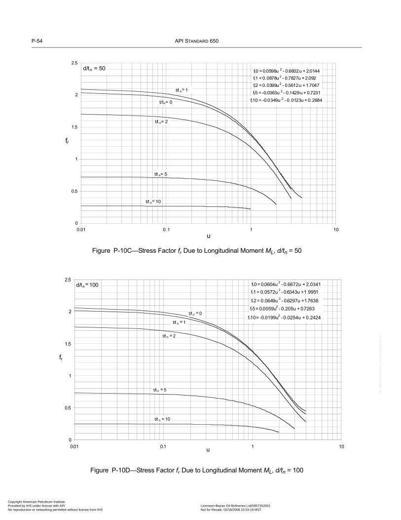
P-54 API STANDARD 650
Copyright AmProvided by No reproduc
--``,,,,,,`,,`,`,`,``,,````,,``-`-`,,`,,`,`,,`---
Figure P-10C—Stress Factor fr Due to Longitudinal Moment ML, d/tn = 50
Figure P-10D—Stress Factor fr Due to Longitudinal Moment ML, d/tn = 100
fr2 = 0.0399u2
- 0.5612u + 1.7047
fr5 = -0.0363u 2 - 0.1429u + 0.7231
fr10 = -0.0349u 2 - 0.0123u + 0.2684
fr1 = 0.0878u 2 - 0.7827u + 2.092
fr0 = 0.0598u 2 - 0.6602u + 2.0144
0
0.5
1
1.5
2
2.5
0.01 0.1 1 10
u
fr
d/tn = 5 0
t/tn= 0
t/t n= 1
t/t n= 2
t/t n= 5
t/t n= 10
fr0= 0.0604u2
- 0.6672u + 2.0341
fr1= 0.0572u2- 0.6343u +1.9951
fr2= 0.0649u2
- 0.6297u +1.7638
fr5= 0.0059u2
- 0.205u + 0.7263
fr10= -0.0199u2
- 0.0254u + 0.2424
0
0.5
1
1.5
2
2.5
0.01 0.1 1 10u
fr
d/tn= 100
t/t n = 0
t/t n = 1
t/t n = 2
t/t n = 5
t/t n = 10
erican Petroleum Institute IHS under license with API Licensee=Bazan Oil Refineries Ltd/5957352001
Not for Resale, 02/18/2008 23:53:18 MSTtion or networking permitted without license from IHS

WELDED STEEL TANKS FOR OIL STORAGE P-55
Copyright AmericaProvided by IHS uNo reproduction o
Figure P-10E—Stress Factor fθ Due to Longitudinal Moment ML, d/tn = 10
Figure P-10F—Stress Factor fθ Due to Longitudinal Moment ML, d/tn = 30
f 0= 0.0186u2 - 0.2026u + 0.6093
f 1 = 0.0769u2- 0.42 u+ 0.8174
f 2 = 0.4177u2
-0.9351u + 1.3637
f 5 = -1.655u 2 - 0.3351u + 2.0292
0
0.5
1
1.5
2
2.5
0.01 0.1 1 10
u
f
d/tn=10
t/tn = 0
t/tn = 1
t/tn = 2
t/tn= 5
f 0 = 0.0189u2
- 0.2054u + 0.6136
f 1 = 0.0205u2
- 0.2132u + 0.7797
f 2 = 0.0737u2
- 0.4233u + 1.2067
f 5 = 0.0201u2
- 0.3208u + 2.0191
f 10 = 1.0841u2
- 0.7196u + 2.4196
0
0.5
1
1.5
2
2.5
3
0 01 0 1 1 10
f
d/tn = 30
t/tn =0
t/tn=1
t/tn= 2
t/tn=5
t/tn=10
n Petroleum Institute nder license with API Licensee=Bazan Oil Refineries Ltd/5957352001
Not for Resale, 02/18/2008 23:53:18 MSTr networking permitted without license from IHS
--``,,,,,,`,,`,`,`,``,,````,,``-`-`,,`,,`,`,,`---

P-56 API STANDARD 650
Copyright AmProvided by No reproduc
Figure P-10G—Stress Factor fθ Due to Longitudinal Moment ML, d/tn = 50
Figure P-10H—Stress Factor fθ Due to Longitudinal Moment ML, d/tn = 100
f 0 = 0.019u2 - 0.2047u+ 0.6084
f 1 = 0.0064u2 - 0.1406u + 0.7319
f 2 = 0.0223u2 - 0.294u + 1.1225
f 5 = -0.1135u 2 - 0.2031u + 2.0016
f 10 = -0.2506u2 + 0.0373u + 2.3705
0
0.5
1
1.5
2
2.5
3
0.01 0.1 1 10u
f
d/tn= 50
t/tn= 0
t/t n= 1
t/tn= 2
t/tn= 5
t/tn= 10
f 0 = 0.0191u2 - 0.2068u + 0.6145
f 1 = 0.0035u2 - 0.0968u + 0.6486
f 2 = 0.0119u2 - 0.2151u + 1.0336
f 5 = -0.0554u2
- 0.2536u + 1.9884
f 10 = -0 .1413u2
- 0.0926u + 2.4238
0
0.5
1
1.5
2
2.5
3
0.01 0.1 1 10u
f
d/tn= 100
t/t n = 0
t/tn = 1
t/tn = 2
t/tn = 5
t/tn =10
erican Petroleum Institute IHS under license with API Licensee=Bazan Oil Refineries Ltd/5957352001
Not for Resale, 02/18/2008 23:53:18 MSTtion or networking permitted without license from IHS
--``,,,,,,`,,`,`,`,``,,````,,``-`-`,,`,,`,`,,`---

WELDED STEEL TANKS FOR OIL STORAGE P-57
Copyright AmericaProvided by IHS uNo reproduction o
Figure P-11—Stress Reduction Factor
0
0.1
0.2
0.3
0.4
0.5
0.6
0.7
0.8
0.9
1
0 0.1 0.2 0.3 0.4 0.5 0.6 0.7 0.8 0.9 1
z, Stress Reduction Factor
h, H
eigh
t Fac
tor
--``,,,,,,`,,`,`,`,``,,````,,``-`-`,,`,,`,`,,`---
n Petroleum Institute nder license with API Licensee=Bazan Oil Refineries Ltd/5957352001
Not for Resale, 02/18/2008 23:53:18 MSTr networking permitted without license from IHS

Copyright AmProvided by No reproduc
--``,,,,,,`,,`,`,`,``,,````,,``-`-`,,`,,`,`,,`---
erican Petroleum Institute IHS under license with API Licensee=Bazan Oil Refineries Ltd/5957352001
Not for Resale, 02/18/2008 23:53:18 MSTtion or networking permitted without license from IHS

07
•
Copyright American Petroleum Institute Provided by IHS under license with API No reproduction or networking permitted without lic
--``,,,,,,`,,`,`,`,``,,````,,``-`-`,,`,,`,`,,`---
APPENDIX R—LOAD COMBINATIONS
R.1 For the purposes of this Standard, loads are combined in the following manner.Design rules account for these load combinations, including the absence of any load otherthan DL in the combinations:
(a) Fluid and Internal Pressure:DL + F + Pi
(b) Hydrostatic Test:DL + (Ht + Pt)
(c) Wind and Internal Pressure:DL + W + 0.4Pi
(d) Wind and External Pressure:DL + W + 0.4Pe
(e) Gravity Loads:1) DL +(Lr or S) + 0.4Pe
2) DL + Pe + 0.4(Lr or S)
(f) Seismic:DL + F + E + 0.1S + 0.4Pi
R.2 If the ratio of operating pressure to design pressure exceeds 0.4, the Purchaser shouldconsider specifying a higher factor on design pressure in (c), (d), (e)(1), and (f).
R-1
Licensee=Bazan Oil Refineries Ltd/5957352001 Not for Resale, 02/18/2008 23:53:18 MSTense from IHS

Copyright AmProvided by No reproduc
--``,,,
,,,`,,`,`,`,``,,````,,``-`-`,,`,,`,`,,`---erican Petroleum Institute IHS under license with API Licensee=Bazan Oil Refineries Ltd/5957352001
Not for Resale, 02/18/2008 23:53:18 MSTtion or networking permitted without license from IHS

•
••••
Copyright AmericaProvided by IHS uNo reproduction o
APPENDIX S—AUSTENITIC STAINLESS STEEL STORAGE TANKS
S.1 ScopeS.1.1 This appendix covers materials, design, fabrication, erection, and testing requirements for vertical, cylindrical, above-ground, closed- and open-top, welded, austenitic stainless steel storage tanks constructed of material grades 304, 304L, 316,316L, 317, and 317L. This appendix does not cover stainless steel clad plate or strip-lined construction.S.1.2 This appendix applies only to tanks in nonrefrigerated services with a maximum design temperature not exceeding 260°C(500°F). Tanks designed to this appendix shall be assigned a maximum design temperature no less than 40°C (100°F). It is cau-tioned that exothermic reactions occurring inside unheated storage tanks can produce temperatures exceeding 40°C (100°F). S.1.3 This appendix is intended to provide the petroleum industry, chemical industry, and other users with tanks of safe designfor containment of fluids within the design limits.S.1.4 The minimum thicknesses in this appendix do not contain any allowance for corrosion.S.1.5 This appendix states only the requirements that differ from the basic rules in this Standard. For requirements not stated,the basic rules must be followed.
S.2 MaterialsS.2.1 SELECTION AND ORDERING
S.2.1.1 Materials shall be in accordance with Table S-1.
Table S-1a—ASTM Materials for Stainless Steel Components (SI Units)
Plates and Structural Members (Note 1)
Piping and Tubing—Seamless or Welded (Note 2) Forgings (Notes 2, 3) Bolting and Bars (Notes 4, 5)
A 240M, Type 304 A 213M, Grade TP 304 A 182M, Grade F 304 A 193M, Class 1, Grades B8, B8A, and B8MA 240M, Type 304L A 213M, Grade TP 304L A 182M, Grade F 304L A 194M, Grades B8, B8A, B8M, and B8MAA 240M, Type 316 A 213M, Grade TP 316 A 182M, Grade F 316 A 320M, Grades B8, B8A, B8M, and B8MAA 240M, Type 316L A 213M, Grade TP 316L A 182M, Grade F 316L A 479M, Type 304A 240M, Type 317 A 213M, Grade TP 317 A 182M, Grade F 317 A 479M, Type 304LA 240M, Type 317L A 213M, Grade TP 317L A 182M, Grade F 317L A 479M, Type 316
A 312M, Grade TP 304 A 479M, Type 316LA 312M, Grade TP 304L A 479M, Type 317A 312M, Grade TP 316A 312M, Grade TP 316LA 312M, Grade TP 317A 312M, Grade TP 317LA 358M, Grade 304A 358M, Grade 304LA 358M, Grade 316A 358M, Grade 316LA 403M, Class WP 304A 403M, Class WP 304LA 403M, Class WP 316A 403M, Class WP 316LA 403M, Class WP 317A 403M, Class WP 317L
Notes:1. Unless otherwise specified by the Purchaser, plate, sheet, or strip shall be furnished with a No. 1 finish and shall be hot-rolled, annealed, and
descaled. 2. Carbon steel flanges and/or stub ends may be used by agreement between the Purchaser and the Manufacturer, providing the design and
details consider the dissimilar properties of the materials used and are suitable for the intended service. 3. Castings shall not be used unless specified by the Purchaser. If specified, castings shall meet ASTM A 351 and shall be inspected in accor-
dance with ASME Boiler and Pressure Vessel Code, Section VIII, Division 1, Appendix 7.4. All bars in contact with the product shall be furnished in the hot-rolled, annealed, and descaled condition.5. Other bolting materials may be used by agreement between the Purchaser and the Manufacturer.
--``,,,,,,`,,`,`,`,``,,````,,``-`-`,,`,,`,`,,`---
S-1
n Petroleum Institute nder license with API Licensee=Bazan Oil Refineries Ltd/5957352001
Not for Resale, 02/18/2008 23:53:18 MSTr networking permitted without license from IHS

S-2 API STANDARD 650
•••
•
•
07
•
Copyright AmProvided by No reproduc
S.2.1.2 Selection of the type/grade of stainless steel depends on the service and environment to which it will be exposed andthe effects of fabrication processes (see S.4.3.2 and S.4.4.3). The Purchaser shall select the type/grade.
S.2.1.3 External structural attachments may be carbon steels meeting the requirements of Section 4 of this Standard, providingthey are protected from corrosion and the design and details consider the dissimilar properties of the materials used. (This doesnot include shell, roof, or bottom openings and their reinforcement.) Carbon steel attachments (e.g., clips for scaffolding) shall notbe welded directly to any internal surface of the tank. For stainless steel tanks subject to external fire impingement, the use of gal-vanizing on attachments, including ladders and platforms, is not recommended.
S.2.2 PACKAGING
Packaging stainless steel for shipment is important to its corrosion resistance. Precautions to protect the surface of the materialwill depend on the surface finish supplied and may vary among manufacturers. Normal packaging methods may not be sufficientto protect the material from normal shipping damage. If the intended service requires special precautions, special instructionsshould be specified by the Purchaser.
S.2.3 IMPACT TESTING
Impact tests are not required for austenitic stainless steel base metals.
Table S-1b—ASTM Materials for Stainless Steel Components (US Customary units)
Plates and Structural Members (Note 1)
Piping and Tubing—Seamless or Welded (Note 2) Forgings (Notes 2, 3) Bolting and Bars (Notes 4, 5)
A 240, Type 304 A213, Grade TP 304 A 182, Grade F 304 A 193, Class 1, Grades B8, B8A, and B8MA 240, Type 304L A213, Grade TP 304L A 182, Grade F 304L A 194, Grades 8, 8A, 8M, and 8MAA 240, Type 316 A213, Grade TP 316 A 182, Grade F 316 A320, Grades B8, B8A, B8M, and B8MAA 240, Type 316L A213, Grade TP 316L A 182, Grade F 316L A 479, Type 304A 240, Type 317 A213, Grade TP 317 A 182, Grade F 317 A 479, Type 304LA 240, Type 317L A213, Grade TP 317L A 182, Grade F 317L A 479, Type 316A 276, Type 304 A 312, Grade TP 304 A 479, Type 316LA 276, Type 304L A 312, Grade TP 304L A 479, Type 317A 276, Type 316 A 312, Grade TP 316A 276, Type 316L A 312, Grade TP 316LA 276, Type 317 A 312, Grade TP 317
A 312, Grade TP 317LA 358, Grade 304A 358, Grade 304LA 358, Grade 316A 358, Grade 316LA 403, Class WP 304A 403, Class WP 304LA 403, Class WP 316A 403, Class WP 316LA 403, Class WP 317A 403, Class WP 317L
Notes:1. Unless otherwise specified by the Purchaser, plate, sheet, or strip shall be furnished with a No. 1 finish and shall be hot-rolled, annealed, and
descaled.2. Carbon steel flanges and/or stub ends may be used by agreement between the Purchaser and the Manufacturer, providing the design and
details consider the dissimilar properties of the materials used and are suitable for the intended service. 3. Castings shall not be used unless specified by the Purchaser. If specified, castings shall meet ASTM A 351 and shall be inspected in accor-
dance with ASME Boiler and Pressure Vessel Code, Section VIII, Division 1, Appendix 7.4. All bars in contact with the product shall be furnished in the hot-rolled, annealed, and descaled condition.5. Other bolting materials may be used by agreement between the Purchaser and the Manufacturer.
--``,,,,,,`,,`,`,`,``,,````,,``-`-`,,`,,`,`,,`---
erican Petroleum Institute IHS under license with API Licensee=Bazan Oil Refineries Ltd/5957352001
Not for Resale, 02/18/2008 23:53:18 MSTtion or networking permitted without license from IHS

WELDED STEEL TANKS FOR OIL STORAGE S-3
•
•
•
•
Copyright AmericaProvided by IHS uNo reproduction o
S.3 DesignS.3.1 BOTTOM PLATESAll bottom plates shall have a minimum nominal thickness of 5 mm (3/16 in.), exclusive of any corrosion allowance. Unless oth-erwise agreed to by the Purchaser, all rectangular and sketch plates (bottom plates on which the shell rests that have one end rect-angular) shall have a minimum nominal width of 1200 mm (48 in.).
S.3.2 SHELL DESIGNUnless otherwise agreed to by the Purchaser, the shell plates shall have a minimum width of 1200 mm (48 in.). The required min-imum thickness of shell plates shall be the greater of the values computed by the following formulas and the shell thickness shallbut not be less than the nominal plate thickness listed in 5.6.1.1:In SI units:
+ CA
wheretd = design shell thickness (mm),
tt = hydrostatic test shell thickness (mm),
D = nominal diameter of tank (m) (see 5.6.1.1),H = design liquid level (m) (see 5.6.3.2),G = specific gravity of the liquid to be stored, as specified by the Purchaser,E = joint efficiency, 1.0, 0.85, or 0.70 (see Table S-4),
CA = corrosion allowance (mm), as specified by the Purchaser (see 5.3.2),Sd = allowable stress for the design condition (MPa) (see Table S-2),
St = allowable stress for hydrostatic test condition (MPa) (see Table S-3).
In US Customary units:
+ CA
wheretd = design shell thickness (in.),
tt = hydrostatic test shell thickness (in.),
D = nominal diameter of tank (ft) (see 5.6.1.1),H = design liquid level (ft) (see 5.6.3.2),G = specific gravity of the liquid to be stored, as specified by the Purchaser,E = joint efficiency, 1.0, 0.85, or 0.70 (see Table S-4),
CA = corrosion allowance (in.), as specified by the Purchaser (see 5.3.2),
Sd = allowable stress for the design condition (lbf/in.2) (see Table S-2),
St = allowable stress for hydrostatic test condition (lbf/in.2) (see Table S-2).
Note: The allowable stresses recognize the increased toughness of stainless steels over carbon steels and the relatively low yield/tensile ratios ofthe stainless steels. The increased toughness permits designing to a higher proportion of the yield strength, however, the Manufacturer and Pur-chaser shall be aware that this may result in permanent strain (see Table S-2).
td4.9D H 0.3–( )G
Sd( )E---------------------------------------=
tt4.9D H 0.3–( )
St( ) E( )----------------------------------=
td2.6D H 1–( )G
Sd( )E----------------------------------=
tt2.6D H 1–( )
St( ) E( )------------------------------=
--``,,,,,,`,,`,`,`,``,,````,,``-`-`,,`,,`,`,,`---
n Petroleum Institute nder license with API Licensee=Bazan Oil Refineries Ltd/5957352001
Not for Resale, 02/18/2008 23:53:18 MSTr networking permitted without license from IHS

S-4 API STANDARD 650
07
Copyright AmProvided by No reproduc
--``,,,,
S.3.3 SHELL OPENINGS
S.3.3.1 The minimum nominal thickness of connections and openings shall be as follows:
Note: Reinforcement requirements of 5.7 must be maintained.
S.3.3.2 Thermal stress relief requirements of 5.7.4 are not applicable.
S.3.3.3 Shell manholes shall be in conformance with 5.7.5 except that the minimum thickness requirements shall be multipliedby the greater of (a) the ratio of the material yield strength at 40°C (100°F) to the material yield strength at the maximum designtemperature, or (b) the ratio of 205 MPa (30,000 psi) to the material yield strength at the maximum design temperature.
S.3.3.4 As an alternative to S.3.3.3, plate ring flanges may be designed in accordance with API Std 620 rules using the allow-able stresses given in Table S-3.
S.3.3.5 Allowable weld stresses for shell openings shall conform to 5.7.2.8 except Sd = the maximum allowable design stress(the lesser value of the base materials joined) permitted by Table S-2.
S.3.4 ROOF MANHOLES
All stainless steel components of the roof manhole shall have a minimum thickness of 5 mm (3/16 in.).
S.3.5 APPENDIX F—MODIFICATIONS
S.3.5.1 In F.4.1 and F.5.1, the values of 1.1 in the SI formula and 212 MPa (30,800 psi) in the US Customary formula shall bemultiplied by the ratio of the material yield strength at the maximum design temperature to 220 MPa (32,000 psi). (See Table S-5for yield strength.)
S.3.5.2 In F.7.1, the shell thickness shall be as specified in S.3.2 except that the pressure P (in kPa [in. of water]) divided by9.8G (12G) shall be added to the design liquid height in meters (ft).
S.3.5.3 In F.7.2, the allowable compressive stress of 140 MPa (20,000 psi) shall be multiplied by the ratio of the material yieldstress at the maximum design temperature to 220 MPa (32,000 psi). (See Table S-5 for yield strength.)
S.3.6 APPENDIX M—MODIFICATIONS
S.3.6.1 Appendix M requirements shall be met for stainless steel tanks with a maximum design temperature over 40°C (100°F)as modified by S.3.6.2 through S.3.6.7.
S.3.6.2 Allowable shell stress shall be in accordance with Table S-2.
S.3.6.3 In M.3.4, the requirements of 5.7.7 for flush-type cleanout fittings and of 5.7.8 for flush-type shell connections shall bemodified. The thickness of the bottom reinforcing plate, bolting flange, and cover plate shall be multiplied by the greater of (a) theratio of the material yield strength at 40°C (100°F) to the material yield strength at the maximum design temperature, or (b) theratio of 205 MPa (30,000 psi) to the material yield strength at the maximum design temperature. (See Table S-5 for yield strength.)
S.3.6.4 In M.3.5, the stainless steel structural allowable stress shall be multiplied by the ratio of the material yield strength atthe maximum design temperature to the material yield strength at 40°C (100°F). (See Table S-5 for yield strength.)
S.3.6.5 The requirements of M.3.6 and M.3.7 are to be modified per S.3.5.1.
S.3.6.6 In M.5.1, the requirements of 5.10.5 and 5.10.6 shall be multiplied by the ratio of the material modulus of elasticity at40°C (100°F) to the material modulus of elasticity at the maximum design temperature. (See Table S-6 for modulus of elasticity.)
S.3.6.7 In M.6 (the equation for the maximum height of unstiffened shell in 3.9.7.1), the maximum height shall be multipliedby the ratio of the material modulus of elasticity at the maximum design temperature to the material modulus of elasticity at 40°C(100°F).
Size of NozzleMinimum Nominal
Neck ThicknessNPS 2 and less Schedule 80SNPS 3 and NPS 4 Schedule 40SOver NPS 4 6 mm (0.25 in.)
erican Petroleum Institute IHS under license with API Licensee=Bazan Oil Refineries Ltd/5957352001
Not for Resale, 02/18/2008 23:53:18 MSTtion or networking permitted without license from IHS
,,`,,`,`,`,``,,````,,``-`-`,,`,,`,`,,`---

WELDED STEEL TANKS FOR OIL STORAGE S-5
•
•
•
Copyright AmericaProvided by IHS uNo reproduction o
S.4 Fabrication and ConstructionS.4.1 GENERAL
Special precautions must be observed to minimize the risk of damage to the corrosion resistance of stainless steel. Stainless steelshall be handled so as to minimize contact with iron or other types of steel during all phases of fabrication and construction. Thefollowing sections describe the major precautions that should be observed during fabrication and handling.
S.4.2 STORAGE
Storage should be under cover and well removed from shop dirt and fumes from pickling operations. If outside storage is neces-sary, provisions should be made for rainwater to drain and allow the material to dry. Stainless steel should not be stored in contactwith carbon steel. Materials containing chlorides, including foods, beverages, oils, and greases, should not come in contact withstainless steel.
S.4.3 THERMAL CUTTING
S.4.3.1 Thermal cutting of stainless steel shall be by the iron powder burning carbon arc or the plasma-arc method.
S.4.3.2 Thermal cutting of stainless steel may leave a heat-affected zone and intergranular carbide precipitates. This heat-affected zone may have reduced corrosion resistance unless removed by machining, grinding, or solution annealing and quench-ing. The Purchaser shall specify if the heat-affected zone is to be removed.
S.4.4 FORMING
S.4.4.1 Stainless steels shall be formed by a cold, warm, or hot forming procedure that is noninjurious to the material.
S.4.4.2 Stainless steels may be cold formed, providing the maximum strain produced by such forming does not exceed 10%and control of forming spring-back is provided in the forming procedure.
S.4.4.3 Warm forming at 540°C (1000°F) – 650°C (1200°F) may cause intergranular carbide precipitation in 304, 316, and 317grades of stainless steel. Unless stainless steel in this sensitized condition is acceptable for the service of the equipment, it will benecessary to use 304L, 316L, or 317L grades or to solution anneal and quench after forming. Warm forming shall be performedonly with agreement of the Purchaser.
S.4.4.4 Hot forming, if required, may be performed within a temperature range of 900°C (1650°F) – 1200°C (2200°F).
S.4.4.5 Forming at temperatures between 650°C (1200°F) and 900°C (1650°F) is not permitted.
S.4.5 CLEANING
S.4.5.1 When the Purchaser requires cleaning to remove surface contaminants that may impair the normal corrosion resistance,it shall be done in accordance with ASTM A 380, unless otherwise specified. Any additional cleanliness requirements for theintended service shall be specified by the Purchaser.
S.4.5.2 When welding is completed, flux residue and weld spatter shall be removed mechanically using stainless steel tools.
S.4.5.3 Removal of excess weld metal, if required, shall be done with a grinding wheel or belt that has not been previouslyused on other metals.
S.4.5.4 Chemical cleaners used shall not have a detrimental effect on the stainless steel and welded joints and shall be disposedof in accordance with laws and regulations governing the disposal of such chemicals. The use of chemical cleaners shall alwaysbe followed by thorough rinsing with water and drying (see S.4.9).
S.4.6 BLAST CLEANING
If blast cleaning is necessary, it shall be done with sharp acicular grains of sand or grit containing not more than 2% by weightiron as free iron or iron oxide. Steel shot or sand used previously to clean nonstainless steel is not permitted.
n Petroleum Institute nder license with API Licensee=Bazan Oil Refineries Ltd/5957352001
Not for Resale, 02/18/2008 23:53:18 MSTr networking permitted without license from IHS
--``,,,,,,`,,`,`,`,``,,````,,``-`-`,,`,,`,`,,`---

S-6 API STANDARD 650
07
•07
•
07
•
Copyright AmProvided by No reproduc
``,,,,,,`,,`,`,`,``,,````,,``-`-`,,`,,`,`,,`---
Table S-2—Allowable Stresses for Plate Ring Flanges
TypeMin. Yield MPa (psi)
Min. TensileMPa (psi)
Allowable Stress (in MPa [psi]) for Maximum Design Temperature Not Exceeding (Sd)
40°C (100°F) 90°C (200°F) 150°C (300°F) 200°C (400°F) 260°C (500°F) St Ambient
304 205 (30,000) 515 (75,000) 155 (22,500) 155 (22,500) 140 (20,300) 128 (18,600) 121 (17,500) 186 (27,000)
304L 170 (25,000) 485 (70,000) 145 (21,000) 132 (19,200) 119 (17,200) 109 (15,800) 101 (14,700) 155 (22,500)
316 205 (30,000) 515 (75,000) 155 (22,500) 155 (22,500) 145 (21,000) 133 (19,300) 123 (17,900) 186 (27,000)
316L 170 (25,000) 485 (70,000) 145 (21,000) 131 (19,000) 117 (17,000) 107 (15,500) 99 (14,300) 155 (22,500)
317 205 (30,000) 515 (75,000) 155 (22,500) 155 (22,500) 145 (21,000) 133 (19,300) 123 (17,900) 186 (27,000)
317L 205 (30,000) 515 (75,000) 155 (22,500) 155 (22,500) 145 (21,000) 133 (19,300) 123 (17,900) 186 (27,000)
Notes:1. Sd may be interpolated between temperatures.2. The design stress shall be the lesser of 0.3 of the minimum tensile strength or 0.9 of the minimum yield strength. The factor of 0.9 of yield
corresponds to a permanent strain of 0.10%. When a lower level of permanent strain is desired, the Purchaser shall specify a reduced yield factor in accordance with Table Y-2 of ASME Section II, Part D. The yield values at the different maximum design temperatures can be obtained from Table S-5.
3. For dual-certified materials (e.g., ASTM A 182M/A 182 Type 304L/304), use the allowable stress of the grade specified by the Purchaser.
Table S-3—Allowable Stresses for Plate Ring Flanges
Allowable Stress (in MPa [psi]) for Maximum Design Temperature Not Exceeding (St)
Type 40°C (100°F) 90°C (200°F) 150°C (300°F) 200°C (400°F) 260°C (500°F)
304 140 (20,000) 115 (16,700) 103 (15,000) 95 (13,800) 89 (12,900)
304L 117 (16,700) 99 (14,300) 88 (12,800) 81 (11,700) 75 (10,900)
316 140 (20,000) 119 (17,200) 107 (15,500) 99 (14,300) 92 (13,300)
316L 117 (16,700) 97 (14,100) 87 (12,600) 79 (11,500) 73 (10,600)
317 140 (20,000) 119 (17,300) 108 (15,600) 99 (14,300) 92 (13,300)
317L 140 (20,000) 119 (17,300) 108 (15,600) 99 (14,300) 92 (13,300)
Notes:1. Allowable stresses may be interpolated between temperatures.2. The allowable stresses are based on a lower level of permanent strain.3. The design stress shall be the lesser of 0.3 of the minimum tensile strength or 2/3 of the minimum yield strength.4. For dual-certified materials (e.g., ASTM A 182M/A 182 Type 304L/304), use the allowable stress of the grade specified by the Purchaser.
Table S-4—Joint Efficiencies
Joint Efficiency Radiograph Requirements
1.0 Radiograph per 8.1.2
0.85 Radiograph per A.5.3
0.70 No radiography required
erican Petroleum Institute IHS under license with API Licensee=Bazan Oil Refineries Ltd/5957352001
Not for Resale, 02/18/2008 23:53:18 MSTtion or networking permitted without license from IHS
--
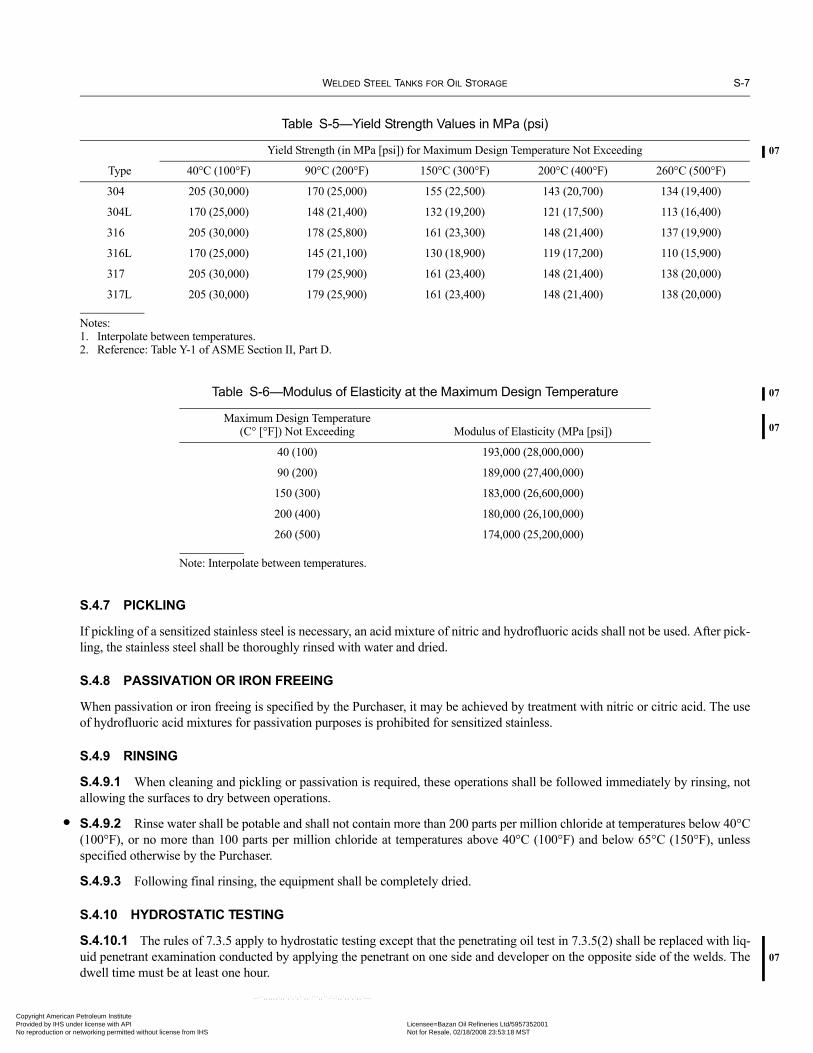
WELDED STEEL TANKS FOR OIL STORAGE S-7
07
07
07
•
07
Copyright AmericaProvided by IHS uNo reproduction o
S.4.7 PICKLING
If pickling of a sensitized stainless steel is necessary, an acid mixture of nitric and hydrofluoric acids shall not be used. After pick-ling, the stainless steel shall be thoroughly rinsed with water and dried.
S.4.8 PASSIVATION OR IRON FREEING
When passivation or iron freeing is specified by the Purchaser, it may be achieved by treatment with nitric or citric acid. The useof hydrofluoric acid mixtures for passivation purposes is prohibited for sensitized stainless.
S.4.9 RINSING
S.4.9.1 When cleaning and pickling or passivation is required, these operations shall be followed immediately by rinsing, notallowing the surfaces to dry between operations.
S.4.9.2 Rinse water shall be potable and shall not contain more than 200 parts per million chloride at temperatures below 40°C(100°F), or no more than 100 parts per million chloride at temperatures above 40°C (100°F) and below 65°C (150°F), unlessspecified otherwise by the Purchaser.
S.4.9.3 Following final rinsing, the equipment shall be completely dried.
S.4.10 HYDROSTATIC TESTING
S.4.10.1 The rules of 7.3.5 apply to hydrostatic testing except that the penetrating oil test in 7.3.5(2) shall be replaced with liq-uid penetrant examination conducted by applying the penetrant on one side and developer on the opposite side of the welds. Thedwell time must be at least one hour.
Table S-5—Yield Strength Values in MPa (psi)
Type
Yield Strength (in MPa [psi]) for Maximum Design Temperature Not Exceeding
40°C (100°F) 90°C (200°F) 150°C (300°F) 200°C (400°F) 260°C (500°F)
304 205 (30,000) 170 (25,000) 155 (22,500) 143 (20,700) 134 (19,400)
304L 170 (25,000) 148 (21,400) 132 (19,200) 121 (17,500) 113 (16,400)
316 205 (30,000) 178 (25,800) 161 (23,300) 148 (21,400) 137 (19,900)
316L 170 (25,000) 145 (21,100) 130 (18,900) 119 (17,200) 110 (15,900)
317 205 (30,000) 179 (25,900) 161 (23,400) 148 (21,400) 138 (20,000)
317L 205 (30,000) 179 (25,900) 161 (23,400) 148 (21,400) 138 (20,000)
Notes:1. Interpolate between temperatures.2. Reference: Table Y-1 of ASME Section II, Part D.
Table S-6—Modulus of Elasticity at the Maximum Design Temperature
Maximum Design Temperature (C° [°F]) Not Exceeding Modulus of Elasticity (MPa [psi])
40 (100) 193,000 (28,000,000)
90 (200) 189,000 (27,400,000)
150 (300) 183,000 (26,600,000)
200 (400) 180,000 (26,100,000)
260 (500) 174,000 (25,200,000)
Note: Interpolate between temperatures.
n Petroleum Institute nder license with API Licensee=Bazan Oil Refineries Ltd/5957352001
Not for Resale, 02/18/2008 23:53:18 MSTr networking permitted without license from IHS
--``,,,,,,`,,`,`,`,``,,````,,``-`-`,,`,,`,`,,`---

S-8 API STANDARD 650
•
•
••
•
Copyright AmProvided by No reproduc
S.4.10.2 The materials used in the construction of stainless steel tanks may be subject to severe pitting, cracking, or rusting ifthey are exposed to contaminated test water for extended periods of time. The Purchaser shall specify a minimum quality of testwater that conforms to the following requirements:
a. Unless otherwise specified by the Purchaser, water used for hydrostatic testing of tanks shall be potable and treated, containingat least 0.2 parts per million free chlorine.b. Water shall be substantially clean and clear.c. Water shall have no objectionable odor (that is, no hydrogen sulfide).d. Water pH shall be between 6 and 8.3.e. Water temperature shall be below 50°C (120°F).f. The chloride content of the water shall be below 50 parts per million, unless specified otherwise by the Purchaser.
S.4.10.3 When testing with potable water, the exposure time shall not exceed 21 days, unless specified otherwise by thePurchaser.
S.4.10.4 When testing with other fresh waters, the exposure time shall not exceed 7 days.
S.4.10.5 Upon completion of the hydrostatic test, water shall be completely drained. Wetted surfaces shall be washed withpotable water when nonpotable water is used for the test and completely dried. Particular attention shall be given to low spots,crevices, and similar areas. Hot air drying is not permitted.
S.4.11 WELDING
S.4.11.1 Tanks and their structural attachments shall be welded by any of the processes permitted in 7.2.1.1 or by the plasmaarc process. Galvanized components or components coated with zinc-rich coating shall not be welded directly to stainless steel.
S.4.11.2 Filler metal chemistry shall match the type of base metals joined. Dissimilar welds to carbon steels shall use fillermetals of E309 or higher alloy content.
S.4.12 WELDING PROCEDURE AND WELDER QUALIFICATIONS
Impact tests are not required for austenitic stainless steel weld metal and heat-affected zones.
S.4.13 POSTWELD HEAT TREATMENT
Postweld heat treatment of austenitic stainless steel materials need not be performed unless specified by the Purchaser.
S.4.14 INSPECTION OF WELDS
S.4.14.1 Radiographic Inspection of Butt-Welds
Radiographic examination of butt-welds shall be in accordance with 8.1 and Table S-4.
S.4.14.2 Inspection of Welds by Liquid Penetrant Method
The following component welds shall be examined by the liquid penetrant method before the hydrostatic test of the tank:
a. The shell-to-bottom inside attachment weld.b. All welds of opening connections in tank shell that are not completely radiographed, including nozzle and manhole neck weldsand neck-to-flange welds.c. All welds of attachments to shells, such as stiffeners, compression rings, clips, and other nonpressure parts for which the thick-ness of both parts joined is greater than 19 mm (3/4 in.).d. All butt-welded joints in tank annular plates on which backing strips are to remain.
S.5 MarkingBrazing shall be deleted from 10.1.2.
erican Petroleum Institute IHS under license with API Licensee=Bazan Oil Refineries Ltd/5957352001
Not for Resale, 02/18/2008 23:53:18 MSTtion or networking permitted without license from IHS
--``,,,,,,`,,`,`,`,``,,````,,``-`-`,,`,,`,`,,`---

WELDED STEEL TANKS FOR OIL STORAGE S-9
•
Copyright AmericaProvided by IHS uNo reproduction o
S.6 AppendicesThe following appendices are modified for use with austenitic stainless steel storage tanks:
a. Appendix C is applicable; however, the Purchaser shall identify all materials of construction.b. Appendix F is modified as outlined in S.3.5 of this appendix.c. Appendix J is applicable, except the minimum shell thickness for all tank diameters is 5 mm (3/16 in.).d. Appendix K is not applicable to tanks built to this appendix.e. Appendix M is modified as outlined in S.3.6 of this appendix.f. Appendix N is not applicable.g. Appendix O is applicable; however, the structural members of Table O-1 shall be of an acceptable grade of material. h. All other appendices are applicable without modifications.
n Petroleum Institute nder license with API Licensee=Bazan Oil Refineries Ltd/5957352001
Not for Resale, 02/18/2008 23:53:18 MSTr networking permitted without license from IHS
--``,,,,,,`,,`,`,`,``,,````,,``-`-`,,`,,`,`,,`---

Copyright AmProvided by No reproduc
--``,,,,,,`,,`,`,`,``,,````,,``-`-`,,`,,`,`,,`---
erican Petroleum Institute IHS under license with API Licensee=Bazan Oil Refineries Ltd/5957352001
Not for Resale, 02/18/2008 23:53:18 MSTtion or networking permitted without license from IHS

07
Copyright AmericaProvided by IHS uNo reproduction o
APPENDIX T—NDE REQUIREMENTS SUMMARY
Process Welds Requiring InspectionReference
SectionAir Test Reinforcement plate welds inside and outside to 100 kPa (15 lbf/in.2). 7.3.4Air Test Roofs designed to be airtight if roof seams are not vacuum-box tested. 7.3.7.1aAir Test Appendix F roofs during hydro-test of tanks. F.4.4Air Test Aluminum dome roofs if required to be gas-tight. G.10.1.2Air Test Shop built tanks if not tested per 7.3.2 – 7.3.7. J.4.2.2Air Test Shop fabricated compartments (pontoons). Test in shop and field. H.6.4Hydro Tank shell. 7.3.6MT Flush-type shell connections: Nozzle-to-tank shell, Repad welds, shell-to-bottom reinforcing
pad welds on the root pass, each 12.5 mm (1/2 in.) of weld, and completed weld. After stressrelieving before hydro-test.
5.7.8.11
MT Permanent attachment welds and temporary weld removal areas on Group IV, IVA, V, and VImaterials.
7.2.3.5
MT Completed welds of stress relieved assemblies before hydro-test. 7.2.3.6MT First pass of the internal shell-to-bottom weld unless inspected by penetrating oil or PT or VB.
Not required if the final weld is tested by pressure (see 7.3.4.2) or if agreed to by Purchaserand the final weld is tested by MT, PT or VB.
7.2.4.1a
MT Final shell-to-bottom welds, inside and outside instead of MT, PT, pen. oil, or VB of the initialinside pass.
7.2.4.3c
MT Shell-to-bottom fillet welds including the root pass, 20 mm (1/2 in.), and final surface ofAppendix M tanks for which the stress concentration factor of K = 2.0 is used.
M.4.2
MT Non-structural small attachments such as insulation clips (not supports) studs and pins notwelded by capacitor discharge. Unless tested by liquid penetrant.
7.2.1.11
Pen. Oil All seams of internal floating roofs exposed to liquid or vapors unless VB tested. H.6.2Pen. Oil First pass of the internal shell-to-bottom weld if approved instead of MT or PT. 7.2.4.1dPen. Oil Tank shell if no water for hydrostatic test. 7.3.5Pen. Oil Deck seams of external floating roofs. C.4.2Pen. Oil Welded shell joints above the hydrostatic test water level unless vacuum-box tested. 7.3.6.1Pen. Oil Compartment welds of external floating roofs not tested with internal pressure or VB. C.3.6PT Permanent attachment welds and temporary weld removal areas on Group IV, IVA, V, VI
materials instead of MT if approved.7.2.3.5
PT Welds attaching nozzles, manways, and clean out openings instead of MT if approved. 7.2.3.6PT First pass of the internal shell-to-bottom weld if approved instead of MT. 7.2.4.1b or cPT Final shell-to-bottom welds, inside and outside instead of MT, PT, pen. oil, or VB of the initial
inside pass.7.2.4.3c
PT All aluminum structural welds and components joined by welding. G.11.3PT Stainless steel tank shell-to-bottom welds, opening connections not radiographed all welds of
attachments to shells, and all butt welds of annular plates on which backing strips are toremain.
S.4.14.2
PT Non-structural small attachments such as insulation clips (not supports) studs and pins notwelded by capacitor discharge. Unless tested by magnetic particle.
7.2.1.11
--``,,,,,,`,,`,`,`,``,,````,,``-`-`,,`,,`,`,,`---
T-1
n Petroleum Institute nder license with API Licensee=Bazan Oil Refineries Ltd/5957352001
Not for Resale, 02/18/2008 23:53:18 MSTr networking permitted without license from IHS

T-2 API STANDARD 650
07
Copyright AmProvided by No reproduc
RT Shell plate butt welds unless examined by UT with Purchaser approval. RT is not required forAppendix A, J, and S tanks where the Joint Efficiency of 0.7 is used.
7.3.2.1,A.5.3,S.4.14.1
RT Butt welds of annular plates that are required by 7.5.1 or M.4.1. 8.1.2.9RT Flush-type shell connections: 100% of all longitudinal butt welds in the nozzle neck and tran-
sition piece, if any, and the first circumferential butt weld in the neck closest to the shell,excluding the neck-to-flange weld.
5.7.8.11
RT Shell vertical and horizontal welds which have intersecting openings and repads—100% overweld length 3 times the diameter of the opening.
5.7.3.4
Tracer Gas Entire length of bottom weld joints as an alternative to vacuum-box testing. 7.3.3.bUT Shell plate butt welds if approved by Purchaser. 7.3.2.1VB First pass of the internal shell-to-bottom weld if approved instead of MT, PT, or Pen. Oil. 7.2.4.1eVB Bottom welds. 7.3.4aVB Welds of roofs designed to be gas-tight if not air tested. 7.3.7.1VB All seams of internal floating roofs exposed to liquid or vapors if not tested by penetrating oil. H.6.2VB Seams of flexible membrane liners for leak protection. I.6.2VB Welded shell joints above the hydrostatic test water level unless tested with penetrating oil. 7.3.6.1VB Shell-to-bottom weld joints. 7.2.4.3cVE Flush type shell connections: Nozzle-to-tank shell, repad welds, shell-to-bottom reinforcing
pad welds on the root pass, each 20 mm (1/2 in.) of weld, and completed weld. After stressrelieving before hydro-test.
5.7.8.11
VE Tack of shell butt welds left in place. 7.2.1.8VE Permanent attachment welds and temporary weld removal areas on Group IV, IVA, V, and VI
materials.7.2.3.5
VE Completed welds of stress relieved assemblies before hydro-test. 7.2.3.6VE First pass and final weld inside and outside of the internal shell-to-bottom weld. 7.2.4.1,
7.2.4.2,7.2.4.3
VE All shell plate butt welds. 7.3.2.1VE All fillet welds including roof plate welds. 7.3.2.2VE Upper side of the upper deck welds of pontoon and double deck floating roofs. C.4.4VE All aluminum structural welds and components joined by welding. G.11.3VE Joint fit-up of butt welds of bottoms supported by grillage and each weld pass. I.7.4VE Non-structural small attachments such as insulation clips (not supports) studs and pins
including those welded by capacitor discharge.7.2.1.11
VE Leak barrier, leak barrier penetrations, attachments to ringwalls and other appurtenances. I.6.1VE Bottom welds. 7.3.3VE Roof welds not designed to be gas-tight. 7.3.7.2Water Bottom welds if not vacuum-box or tracer gas tested. 7.3.3cWater External floating roofs—flotation test. C.4.3Water External floating roof drain pipe and hose systems with pressure. C.4.5Water Aluminum dome roofs after completion. G.10.1.1Water Internal floating roofs flotation test. H.7.3
--``,,,,,,`,,`,`,`,``,,````,,``-`-`,,`,,`,`,,`---
erican Petroleum Institute IHS under license with API Licensee=Bazan Oil Refineries Ltd/5957352001
Not for Resale, 02/18/2008 23:53:18 MSTtion or networking permitted without license from IHS

WELDED STEEL TANKS FOR OIL STORAGE T-3
07
Copyright AmericaProvided by IHS uNo reproduction o
Definitions:MT = Magnetic Particle ExaminationPen Oil = Penetrating Oil TestPT = Liquid Penetrant ExaminationRT = Radiographic TestingVB = Vacuum-Box TestingVE = Visual Examination
Acceptance Standards:MT: ASME Section VIII, Appendix 6 (Paragraphs 6-3, 6-4, 6-5)PT: ASME Section VIII, Appendix 8, (Paragraphs 8-3, 8-4, 8-5)RT: ASME Section VIII, Paragraph UW-51(b)Tracer Gas: API Std 650, Section 8.6.11UT: For welds examined by UT in lieu of RT, acceptance standards are in Appendix U. For UT when RT is used for the requirements of 7.3.2.1, the acceptance standard is as agreed upon by the Manufacturer and Purchaser.VB: API Std 650, Section 8.6VE: API Std 650, Section 8.5
Examiner Qualifications:MT: API Std 650, Section 8.2.3. PT: API Std 650, Section 8.2.3RT: ASNT SNT-TC-1A Level II or III. Level-I personnel may be used under the supervision of a Level II or Level III with a written procedure in accordance with ASME Section V, Article 2.Tracer Gas: NoneUT: For welds examined by UT in lieu of RT, the inspector must be ASNT-TC-1A or CP-189 Level II or Level III. For UT when RT is used for the requirements of 7.3.2.1, the required qualifications are ASNT-TC-1A Level II or Level III. A Level I may be used with restrictions—see API Std 650, Section 8.3.2.VB: NoneVE: None
Procedure Requirements:MT: ASME Section V, Article 7PT: ASME Section V, Article 6RT: A procedure is not required. However, the examination method must comply with ASME Section V, Article 2. Acceptance standards shall be in accordance with ASME Section VIII, Paragraph UW-51(b).UT: For shell welds examined by UT in lieu or RT, ASME, Section V, Article 4 and U.3.5. For welds when RT is used for the requirements of 7.3.2.1, ASME Section V.VB: NoneVE: None
Tracer Gas: API Std 650, Section 8.6.11.a.
--``,,,,,,`,,`,`,`,``,,````,,``-`-`,,`,,`,`,,`---
n Petroleum Institute nder license with API Licensee=Bazan Oil Refineries Ltd/5957352001
Not for Resale, 02/18/2008 23:53:18 MSTr networking permitted without license from IHS

Copyright AmProvided by No reproduc
--``,,,,,,`,,`,`,`,``,,````,,``-`-`,,`,,`,`,,`---
erican Petroleum Institute IHS under license with API Licensee=Bazan Oil Refineries Ltd/5957352001
Not for Resale, 02/18/2008 23:53:18 MSTtion or networking permitted without license from IHS

07
•
•
Copyright AmericaProvided by IHS uNo reproduction o
APPENDIX U—ULTRASONIC EXAMINATION IN LIEU OF RADIOGRAPHY
U.1 GeneralU.1.1 PURPOSE
This appendix provides detailed rules for the use of the ultrasonic examination (UT) method for the examination of tank seams aspermitted by 7.3.2.1. This alternative is limited to joints where the thickness of the thinner of the two members joined is greaterthan or equal to 10 mm (3/8 in.).
U.1.2 APPLICATION AND EXTENT
The provisions of 8.1 governing:
a. When adjacent plates may be regarded as the same thickness, b. Application (see 8.1.1), and c. Number and Locations (see 8.1.2)
shall apply to this ultrasonic method. When these sections refer to radiography, for purposes of this appendix, they shall be read asapplied to UT.
U.2 Definitionsa. documenting: Preparation of text and/or and figures.b. evaluation: All activities required in U.6.3 through U.6.6 to determine the acceptability of a flaw.c. flaw: A reflector that is not geometric or metallurgical in origin that may be detectable by nondestructive testing but is notnecessarily rejectable. d. flaw categorization: Whether a flaw is a surface flaw or is a subsurface flaw (see U.6.4). Note that a flaw need not be sur-face-breaking to be categorized as a surface flaw.e. flaw characterization: The process of quantifying the size, location and shape of a flaw. See U.6.3 for size and location.The only shape characterization required by this appendix is applied to the results of supplemental surface examination by MT orPT (see U.6.6.2). f. indication: That which marks or denotes the presence of a reflector.g. interpretation: The determination of whether an indication is relevant or non-relevant. i.e., whether it originates from a geo-metric or metallurgical feature or conversely originates from a flaw (see U.6.2).h. investigation: Activities required to determine the interpretation of an indication (see U.6.1 and U.6.2).i. recording: The writing of ultrasonic data onto an appropriate electronic medium.j. reflector: An interface at which an ultrasonic beam encounters a change in acoustic impedance and at which at least part ofthe energy is reflected.
U.3 TechniqueU.3.1 The UT volume shall include the weld metal, plus the lesser of 25 mm (1 in.) or t of adjoining base metal on each side ofthe weld unless otherwise agreed upon by the Purchaser and the Manufacturer.
U.3.2 UT for the detection of flaws shall be performed using automated, computer-based data acquisition except that scanningof adjacent base metal for flaws that can interfere with the examination may be performed manually. UT for sizing of flaws shallbe performed as described in U.6.3.1
U.3.3 A documented examination strategy or scan plan shall be provided showing transducer placement, movement, and com-ponent coverage that provides a standardized and repeatable methodology for weld acceptance. The scan plan shall also includeultrasonic beam angle to be used, beam directions with respect to weld centerline, and tank material volume examined for eachweld. The documentation shall be made available to the Owner upon request.
--``,,,,,,`,,`,`,`,``,,````,,``-`-`,,`,,`,`,,`---
U-1
n Petroleum Institute nder license with API Licensee=Bazan Oil Refineries Ltd/5957352001
Not for Resale, 02/18/2008 23:53:18 MSTr networking permitted without license from IHS
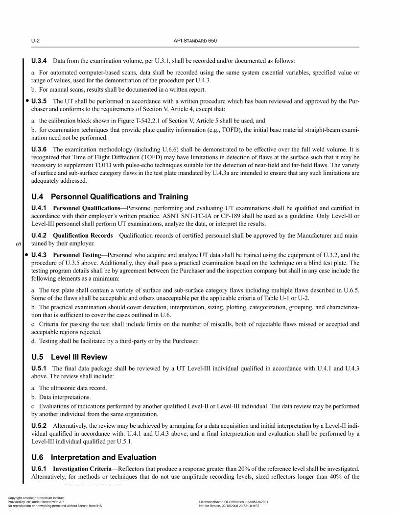
U-2 API STANDARD 650
•
07
•
Copyright AmProvided by No reproduc
U.3.4 Data from the examination volume, per U.3.1, shall be recorded and/or documented as follows:
a. For automated computer-based scans, data shall be recorded using the same system essential variables, specified value orrange of values, used for the demonstration of the procedure per U.4.3.b. For manual scans, results shall be documented in a written report.
U.3.5 The UT shall be performed in accordance with a written procedure which has been reviewed and approved by the Pur-chaser and conforms to the requirements of Section V, Article 4, except that:
a. the calibration block shown in Figure T-542.2.1 of Section V, Article 5 shall be used, andb. for examination techniques that provide plate quality information (e.g., TOFD), the initial base material straight-beam exami-nation need not be performed.
U.3.6 The examination methodology (including U.6.6) shall be demonstrated to be effective over the full weld volume. It isrecognized that Time of Flight Diffraction (TOFD) may have limitations in detection of flaws at the surface such that it may benecessary to supplement TOFD with pulse-echo techniques suitable for the detection of near-field and far-field flaws. The varietyof surface and sub-surface category flaws in the test plate mandated by U.4.3a are intended to ensure that any such limitations areadequately addressed.
U.4 Personnel Qualifications and Training U.4.1 Personnel Qualifications—Personnel performing and evaluating UT examinations shall be qualified and certified inaccordance with their employer’s written practice. ASNT SNT-TC-IA or CP-189 shall be used as a guideline. Only Level-II orLevel-III personnel shall perform UT examinations, analyze the data, or interpret the results.
U.4.2 Qualification Records—Qualification records of certified personnel shall be approved by the Manufacturer and main-tained by their employer.
U.4.3 Personnel Testing—Personnel who acquire and analyze UT data shall be trained using the equipment of U.3.2, and theprocedure of U.3.5 above. Additionally, they shall pass a practical examination based on the technique on a blind test plate. Thetesting program details shall be by agreement between the Purchaser and the inspection company but shall in any case include thefollowing elements as a minimum:
a. The test plate shall contain a variety of surface and sub-surface category flaws including multiple flaws described in U.6.5.Some of the flaws shall be acceptable and others unacceptable per the applicable criteria of Table U-1 or U-2.b. The practical examination should cover detection, interpretation, sizing, plotting, categorization, grouping, and characteriza-tion that is sufficient to cover the cases outlined in U.6.c. Criteria for passing the test shall include limits on the number of miscalls, both of rejectable flaws missed or accepted andacceptable regions rejected.d. Testing shall be facilitated by a third-party or by the Purchaser.
U.5 Level III ReviewU.5.1 The final data package shall be reviewed by a UT Level-III individual qualified in accordance with U.4.1 and U.4.3above. The review shall include:
a. The ultrasonic data record.b. Data interpretations.c. Evaluations of indications performed by another qualified Level-II or Level-III individual. The data review may be performedby another individual from the same organization.
U.5.2 Alternatively, the review may be achieved by arranging for a data acquisition and initial interpretation by a Level-II indi-vidual qualified in accordance with. U.4.1 and U.4.3 above, and a final interpretation and evaluation shall be performed by aLevel-III individual qualified per U.5.1.
U.6 Interpretation and EvaluationU.6.1 Investigation Criteria—Reflectors that produce a response greater than 20% of the reference level shall be investigated.Alternatively, for methods or techniques that do not use amplitude recording levels, sized reflectors longer than 40% of the
--``,,,,,,`,,`,`,`,``,,````,,``-`-`,,`,,`,`,,`---
erican Petroleum Institute IHS under license with API Licensee=Bazan Oil Refineries Ltd/5957352001
Not for Resale, 02/18/2008 23:53:18 MSTtion or networking permitted without license from IHS

WELDED STEEL TANKS FOR OIL STORAGE U-3
07
Copyright AmericaProvided by IHS uNo reproduction o
acceptable surface or subsurface flaws in Table U-1 shall be investigated. The investigation shall interpret whether the indicationoriginates from a flaw or is a geometric indication in accordance with U.6.2 below. When the reflector is determined to be a flaw,the flaw shall be evaluated and acceptance criteria of Table U-1 as applicable shall apply.
U.6.2 Interpretation as Geometric/Metallurgical—Ultrasonic indications of geometric and metallurgical origin shall beinterpreted as follows:
U.6.2.1 Indications that are determined to originate from the surface configurations (such as weld reinforcement or root geom-etry) or variations in metallurgical structure of materials may be interpreted as geometric indications, and
a. Need not be sized or categorized in accordance with U.6.3 and U.6.4 below;b. Need not be compared to the allowable flaw acceptance criteria of Table U-1;c. The maximum indication amplitude (if applicable) and location shall be documented, for example: internal attachments, 200%DAC maximum amplitude, one (1) in. above the weld centerline, on the inside surface, from 90° to 95°.
U.6.2.2 The following steps shall be taken to classify an indication as geometric:
a. Interpret the area containing the indication in accordance with the applicable examination procedure;b. Plot and verify the indication’s coordinates, provide a cross-sectional display showing the indication’s position and any surfaceconditions such as root or counter-bore; andc. Review fabrication or weld prep drawings.
U.6.2.3 Alternatively, other NDE methods or techniques may be applied to interpret an indication as geometric (e.g., alterna-tive UT beam angles, radiography, ID and/or OD profiling).
U.6.3 FLAW SIZING
U.6.3.1 Flaws shall be sized using automated, computer-based data acquisition or by a supplemental manual technique that hasbeen demonstrated to perform acceptably per U.4.3 above.
U.6.3.2 The dimensions of the flaw shall be defined by the rectangle that fully contains the area of the flaw. The length (l) ofthe flaw shall be drawn parallel to the inside pressure-retaining surface of the component. The height (h) of the flaw shall bedrawn normal to the inside pressure-retaining surface.
U.6.4 FLAW CATEGORIZATION
If the space between the surface and the flaw in the through-thickness direction is less than one-half the measured height of theflaw, then the flaw shall be categorized as a surface flaw with flaw height extending to the surface of the material.
U.6.5 GROUPING OF MULTIPLE FLAWS
U.6.5.1 Discontinuous flaws that are oriented primarily in parallel planes shall be considered to lie in a single plane if the dis-tance between the adjacent planes is equal to or less than 12 mm (in.).
U.6.5.2 If the space between two flaws aligned along the axis of weld is less than the length of the longer of the two, the twoflaws shall be considered a single flaw.
U.6.5.3 If the space between two flaws aligned in the through-thickness direction is less than the height of the flaw of greaterheight, the two flaws shall be considered a single flaw.
U.6.6 FLAW ACCEPTANCE CRITERIA
U.6.6.1 Acceptance Criteria Tables—Flaw dimensions resulting after the application of the rules of U.6.3, U.6.4 and U.6.5shall be evaluated for acceptance using the criteria of Table U-1.
U.6.6.2 Surface Examination—Flaws categorized as surface flaws during the UT examination may or may not be surface-connected. Therefore, unless the UT data analysis confirms that the flaw is not surface-connected, a supplemental surface exami-nation (MT or PT) shall be performed in accordance with 8.2 or 8.4 as applicable for all surface flaws. Any flaws which aredetected by MT or PT and characterized as planar are unacceptable regardless of length.
n Petroleum Institute nder license with API Licensee=Bazan Oil Refineries Ltd/5957352001
Not for Resale, 02/18/2008 23:53:18 MSTr networking permitted without license from IHS
--``,,,,,,`,,`,`,`,``,,````,,``-`-`,,`,,`,`,,`---

U-4 API STANDARD 650
07
Copyright AmProvided by No reproduc
--``,,,,,,`,,`,`,`,``,,````,,``-`-`,,`,,`,`,,`---
U.7 RepairsAll repaired areas, plus the lesser of 25 mm (1 in.) or t of the adjoining weld on each side of the repair, shall be reinspected per thisAppendix.
U.8 Flaw DocumentationIn addition to the data record prescribed by U.3.4, written documentation shall be produced for each unacceptable flaw and thoseacceptable flaws that either exceed 50% of reference level for amplitude based techniques or exceed 75% of the acceptable lengthfor non-amplitude techniques.
t = thickness of the weld excluding any allowable reinforcement. For a butt weld joining members having different thickness atthe weld, t is the thinner of the two. Any surface flaw, to be deemed acceptable, must satisfy both the size limitations of thistable and additionally satisfy the MT/PT characterization limitations of U.6.6.2
Table U-1—Flaw Acceptance Criteria for UT Indications May be Used for All Materials
Thickness at Weld (t) (1)
mm (in.)
ACCEPTABLE FLAW LENGTHS – (l) mm (in.)
For Surface Flaw (2)
With Height, (h) mm (in.)For SubSurface Flaw
With Height, (h) mm (in.)
2 (0.08) 2.5 (0.10) 3 (0.12) 2 (0.08) 3 (0.12) 4 (0.16) 5 (0.2) 6 (0.24)
10 (0.375) to <13 (0.50) 8(0.30)
8(0.30)
4(0.15)
14(0.55)
5(0.20)
4(0.15)
Notallowed
Notallowed
13 (0.50) to < 19 (0.75) 8(0.30)
8(0.30)
4(0.15)
38(1.50)
8(0.30)
5(0.20)
4(0.15)
3(0.10)
19 (0.75) to < 25 (1.0) 8(0.30)
8(0.30)
4(0.15)
75(3.00)
13(0.50)
8(0.30)
6(0.25)
5(0.20)
25 (1.0) to < 32 (1.25) 9(0.35)
8(0.30)
4(0.15)
100(4.00)
20(0.80)
9(0.35)
8(0.30)
6(0.25)
32 (1.25) to < 38 (1.50) 9(0.35)
8(0.30)
4(0.15)
125(5.00)
30(1.20)
10(0.40)
8(0.30)
8(0.30)
38 (1.50) to < 44 (1.75) 9(0.35)
8(0.30)
4(0.15)
150(6.00)
38(1.50)
10(0.40)
9(0.35)
8(0.30)
erican Petroleum Institute IHS under license with API Licensee=Bazan Oil Refineries Ltd/5957352001
Not for Resale, 02/18/2008 23:53:18 MSTtion or networking permitted without license from IHS

•
Copyright AmericaProvided by IHS uNo reproduction o
APPENDIX V—DESIGN OF STORAGE TANKS FOR EXTERNAL PRESSURE
V.1 ScopeThis appendix provides minimum requirements that may be specified by the Purchaser for tanks that are designed to operate withexternal pressure (vacuum) loading as a normal operating condition. This appendix is intended to apply to tanks for which thenormal operating external pressure exceeds 0.25 kPa (0.036 lbf/in.2) but does not exceed 6.9 kPa (1.0 lbf/in.2). This appendix isintended for use with tanks subject to uniform external pressure. The requirements in this appendix represent accepted practice forapplication to flat-bottom tanks. However, the Purchaser may specify other procedures or additional requirements. Any deviationfrom the requirements of this appendix must be by agreement between the Purchaser and the Manufacturer. See V.11 for a discus-sion of the technical basis for this appendix.
V.2 GeneralThe design procedures presented in this appendix are intended to allow the user to evaluate the design of the bottom, shell andfixed roof of tanks that operate under partial vacuum conditions. See Appendix R for requirements for combining external pres-sure loads with other design loads. The requirements of this appendix are not intended to supersede the requirements of otherappendices of this Standard that may be specified. For Appendix M and S tanks, the variables in the equations prescribed in thisappendix shall be modified in accordance with the requirements of Appendices M and S, respectively.
V.3 Nomenclature and DefinitionsV.3.1 NOMENCLATURE
θ = angle between a horizontal plane and the surface of the roof plate (degrees) Areqd = total required cross-sectional area of the stiffener region, mm2 (in.2) Astiff = required cross-sectional area of stiffener, mm2 (in.2) Note: Astiff must be at least 1/2 x Atotal
D = nominal tank diameter, m (ft)DL = dead load, the weight of the tank or tank component, including any corrosion allowance unless otherwise speci-
fied, kPa (lb/ft2)E = modulus of elasticity of the roof plate material, MPa, (lb/in.2)f = smallest of the allowable tensile stresses (see Table 3-2) of the roof plate material, shell plate material or stiffener
ring material at the maximum operating temperature, MPa (lb/in.2) fc = smallest of the allowable compressive stresses of the roof plate material, shell plate material, bottom plate material
or stiffener ring material at the maximum operating temperature, MPa (lb/in.2). fc = 0.4Fy of components consid-ered for the intermediate and bottom stiffener regions. However, fc need not be less than 103 MPa (15,000 lb/in.2). fc = 0.6Fy of components considered for the top end stiffener region. However, fc need not be less than 140 MPa (20,000 lb/in.2).
Fy = yield strength of the component at the maximum operating temperature, MPa (lb/in.2)Gin = unit weight of liquid inside tank, kg/m3 (lb/ ft3)
Gout = unit weight of flood liquid, kg/m3 (lb/ ft3) (1000 kg/m3 [62.4 lb/ ft3] for water)H = shell height, m (ft)
h1, h2…hn = height of shell courses 1, 2, 3, through n, respectively, m (ft)Hin = height or depth of liquid inside tank, m (ft)
Hsafe = maximum height of unstiffened shell permitted, based on the calculated minimum thickness, m (ft) HTS = Transformed height of tank shell, m (ft)
Iact = The actual moment of inertia of the stiffener ring region, cm4 (in.4)Ireqd = required moment of inertia of the stiffener ring, cm4 (in.4) JEb = Joint efficiency of bottom plate. JEb = 1.0 for bottom jointsJEr = joint efficiency of roof plate. JEr = 0.35 for single lap welds, 0.70 for double lap welds, and 1.0 for butt welds
--``,,,,,,`,,`,`,`,``,,````,,``-`-`,,`,,`,`,,`---
V-1
n Petroleum Institute nder license with API Licensee=Bazan Oil Refineries Ltd/5957352001
Not for Resale, 02/18/2008 23:53:18 MSTr networking permitted without license from IHS

V-2 API STANDARD 650
•
Copyright AmProvided by No reproduc
--``,,,,,,`,,`,`,`,``,,````,,``-`-`,,`,,`,`,,`---
JEs = joint efficiency of shell plate. JEs = 1.0 for shell with full radiography, or 0.85 with spot radiographyJEst = joint efficiency of splice of stiffener sections. JEstiff = 1.0 for 100% radiography of all splice welds, 0.85 for spot
radiography of selected splice welds, and 0.70 for no radiographyL1, L2 = distances between adjacent intermediate stiffeners or intermediate stiffener and top of shell or bottom of shell,
respectively, m (ft)Lr = minimum roof live load on horizontal projected area of the roof, kPa (lb/ft2) = 1.0kPa (20 lb/ft2)Ls = (L1 + L2) / 2, m (ft) N = number of waves into which a shell will buckle under external pressure
Ns = number of intermediate stiffenersPe = specified external pressure, kPa (lb/ft2) Pr = total design external pressure for design of roof, kPa (lb/ft2). Ps = total design external pressure for design of shell, kPa (lb/ft2). Ps = the greater of 1) the specified design external
pressure, Pe, excluding wind or 2) W + 0.4PeQ = radial load imposed on the intermediate stiffener by the shell, N/m (lb/in.)qs = first moment of area of stiffener for design of stiffener attachment weld, mm3 (in.3)R = roof dish radius, m (ft)S = specified snow load, kPa (lb/ft2)
Sd = allowable design stress, Mpa, (lb/in.2)t = shell thickness, including corrosion allowance, mm (in.)
tb = thickness of bottom plate under the shell, including corrosion allowance, mm (in.)tcone = required thickness of cone roof plate, including corrosion allowance, mm (in.). (Maximum 12.5 mm (0.5 in.) excl.
corrosion allowance)tdome = required thickness of dome roof plate, including corrosion allowance, mm (in.) (Maximum 12.5 mm (0.5 in.) excl.
corrosion allowance)ts1, ts2…tsn = thickness of cylindrical shell course 1, 2…n, mm (in.), where the subscript numbering is from top to bottom of the
shell. Note: The subscript 1 denotes the top shell course and n denotes the lowest shell course.tshell = actual thickness of shell at level under consideration, including corrosion allowance, mm (in.)tsmin = minimum thickness of thinnest shell course, mm (in.)
V1 = radial load imposed on the stiffener by the shell, N/m (lb/ft)Vs1 = radial pressure load imposed on the stiffener from the shell for sizing the stiffener attachment weld, N/m (lb/ft)
vs = radial shear load on stiffener for sizing the stiffener attachment weld, N (lb)Vs2 = weld shear flow load imposed for sizing the stiffener attachment weld, N/m (lb/ft)W = maximum wind pressure consistent with the specified design wind velocity, kPa (lb/ft2). The maximum wind
pressure shall be calculated as follows:
In SI units:
W = 0.0000333(V)2(Kg)(Kh)
In US Customary units:
W = 0.001776(V)2(Kg)(Kh)
where
V = specified design wind velocity (3-sec gust), kph (mph),Kg = wind gust factor = 1.1,Kh = wind height factor = 1.1.
Wbott = weight of bottom plate, kg/m2 (lb/ft2)wshell = contributing width of shell on each side of intermediate stiffener, mm (in.)
erican Petroleum Institute IHS under license with API Licensee=Bazan Oil Refineries Ltd/5957352001
Not for Resale, 02/18/2008 23:53:18 MSTtion or networking permitted without license from IHS

WELDED STEEL TANKS FOR OIL STORAGE V-3
•
•
•
•
Copyright AmericaProvided by IHS uNo reproduction o
Xbtm = length of bottom plate within tension/compression ring region, mm (in.). Xbtm = 16 tbXcone = length of cone roof within tension/compression ring region, mm (in.)
Xdome = length of umbrella or dome roof within tension/compression ring region, mm (in.)Xshell = length of shell within tension/compression ring region, mm (in.)
V.3.2 DEFINITIONS
V.3.2.1 specified external pressure: External pressure specified on the tank data sheet (see Appendix L) by the Purchaser.This specified value excludes any external pressure due to wind.
V.3.2.2 total design external pressure for the roof (Pr): Sum of the specified external pressure and the roof live load orsnow load and the dead load as provided in V.7.1.
V.3.2.3 total design external pressure for the shell (P ): Sum of the specified external pressure and the external pres-sure due to wind as combined in V.8.1.2.
V.4 Construction TolerancesThe procedures prescribed in this appendix are only valid for tanks that satisfy the construction tolerances of 7.5.
V.5 Corrosion AllowanceUnless specified otherwise by the Purchaser, the evaluation of tanks in accordance with the requirements of this appendix may bebased on the as-built thickness of the pressure-resisting components, including any specified corrosion allowance. If the nature ofthe tank service conditions is such that corrosion will result in a uniform loss of thickness of the affected components, the Pur-chaser should specify that corrosion allowance be deducted from the as-built thickness used in the evaluation.
V.6 TestingTesting of the tank design for external pressure is not required by this appendix, but may be performed if specified by thePurchaser.
V.7 Fixed RoofThe total design external pressure loading, Pr, on the roof is determined by the following equation:
Pr = The greater of DL + (Lr or S) + 0.4 Pe or DL + Pe + 0.4 (Lr or S)
V.7.1 COLUMN-SUPPORTED CONE ROOF
Column-supported cone roofs may be used on tanks designed for external pressure, providing the design and construction satisfythe following requirements.
V.7.1.1 The roof plate spanning between support rafters may be designed as a simple beam spanning several supports, or as acatenary beam spanning between supports, or as a diaphragm, by agreement between the Purchaser and the Manufacturer.Regardless of the design method selected, the following considerations shall be addressed in the design:
a. Allowable stress for both membrane and bending.b. Joint efficiency of welds joining the roof plates together.c. Assumed end fixity conditions for plate (beam) span.d. Allowable deflection criteria.
If the roof plate is designed as a catenary beam, the following additional considerations shall be addressed in the design.e. Possibility of stress reversal and fatigue loading of welds at and between supports of the roof plate.
V.7.1.2 Additional guidance on the design of supported cone roof plates for pressure loading may be found in References 8 and9, for example, and in other published texts.
--``,,,,,,`,,`,`,`,``,,````,,``-`-`,,`,,`,`,,`---
n Petroleum Institute nder license with API Licensee=Bazan Oil Refineries Ltd/5957352001
Not for Resale, 02/18/2008 23:53:18 MSTr networking permitted without license from IHS

V-4 API STANDARD 650
Copyright AmProvided by No reproduc
--``,,,,,,`,,`,`,`,``,,````,,``-`-`,,`,,`,`,,`---
V.7.2 SELF-SUPPORTING CONE ROOF
V.7.2.1 The required thickness of the roof plate is determined by the following equation. However, the thickness shall not beless than that required by 5.10.5.1.
In SI units:
In US Customary units:
V.7.2.2 The total required cross-sectional area in the cone roof-to-shell joint region for external pressure on the roof is deter-mined by the following equation.
In SI units:
In US Customary units:
V.7.2.3 The length of cone roof considered to be within the top tension/compression ring region is determined by the followingequation (see Figure V.1A):
In SI units:
In US Customary units:
V.7.2.4 The vertical dimension measured from the top of the shell or top angle considered to be within the tension/compressionring region is determined by the following equation (see Figure V.1A):
In SI units:
For the top tension/compression region: For the bottom tension/compression region:
In US Customary units:
For the top tension/compression region: For the bottom tension/compression region:
tcone83Dsine----------
Pr
1.72E--------------=
tconeD
sine---------
Pr
0.248E-----------------=
Areqd125Pr D2
ftane---------------------=
AreqdPr D2
8ftane---------------=
Xcone 13.4Dtcone
sine-------------=
Xcone 1.47Dtcone
sine-------------=
Xshell 13.4 Dtsl= Xshell 13.4 Dtsn=
Xshell 1.47 Dtsl= Xshell 1.47 Dtsn=
erican Petroleum Institute IHS under license with API Licensee=Bazan Oil Refineries Ltd/5957352001
Not for Resale, 02/18/2008 23:53:18 MSTtion or networking permitted without license from IHS

WELDED STEEL TANKS FOR OIL STORAGE V-5
Copyright AmericaProvided by IHS uNo reproduction o
Figure V-1A—Dimensions for Self-Supporting Cone Roof
Note: See Appendix F, Figure F-2 for alternative configurations and associated limitations on structural section used for top stiffener.
h1
Xshell
ts1
ts2h2
hn
tsn
Xbtm
Xshell
tb
H
D
θ
tcone Xcone
--``,,,,,,`,,`,`,`,``,,````,,``-`-`,,`,,`,`,,`---
n Petroleum Institute nder license with API Licensee=Bazan Oil Refineries Ltd/5957352001
Not for Resale, 02/18/2008 23:53:18 MSTr networking permitted without license from IHS

V-6 API STANDARD 650
07
07
Copyright AmProvided by No reproduc
--``,,,,,,`,,`,`,`,``,,````,,``-`-`,,`,,`,`,,`---
V.7.2.5 The required cross-sectional area of the top stiffener structural shape is determined by the following equation:
JEstAstiff = Areqd – JEsts1Xshell – JErtconeXcone
V.7.3 SELF-SUPPORTING DOME OR UMBRELLA ROOF
V.7.3.1 The required thickness of the roof plate is determined by the following equations. However, the thickness shall not beless than that required by 5.10.6.1. (Note that design in accordance with API Std 620 is permitted for dished dome roofs meetingthe requirements of API Std 620, 5.10.5.1.)
In SI units:
(for umbrella and dome roofs)
In US Customary units:
(for umbrella and dome roofs)
V.7.3.2 The total required cross-sectional area in the dome or umbrella roof-to-shell joint region for external pressure on theroof is determined by the following equation. However, the area shall not be less than that required by 5.10.6.2.
In SI units:
In US Customary units:
V.7.3.3 The length of dome or umbrella roof considered to be within the top tension/compression ring region is determined bythe following equation:
In SI units:
In US Customary units:
V.7.3.4 The length of shell considered to be within the top tension/compression ring region is determined by the followingequation (see Figure V.1B):
In SI units:
In US Customary units:
V.7.3.5 The required cross-sectional area of the top stiffener structural shape is determined by the following equation:
JEstAstiff = Areqd – JEsts1Xshell – JErtdomeXdome
tdome 127RPr
E-----=
tdome 4.47RPr
E-----=
Areqd300PrRD
f-----------------------=
AreqdPrRD3.375f---------------=
Xdome 2.1 RTdome=
Xdome 2.1 RTdome=
Xshell 1.47 Dtal=
Xshell 1.47 Dtsl=
erican Petroleum Institute IHS under license with API Licensee=Bazan Oil Refineries Ltd/5957352001
Not for Resale, 02/18/2008 23:53:18 MSTtion or networking permitted without license from IHS
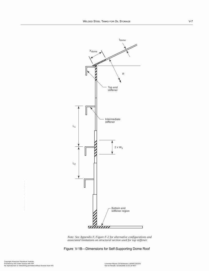
WELDED STEEL TANKS FOR OIL STORAGE V-7
Copyright AmericaProvided by IHS uNo reproduction o
Figure V-1B—Dimensions for Self-Supporting Dome Roof
Bottom endstiffener region
Intermediatestiffener
2 x Ws
L2
L1
Top endstiffener
R
tdome
Xdome
Note: See Appendix F, Figure F-2 for alternative configurations and associated limitations on structural section used for top stiffener.
--``,,,,,,`,,`,`,`,``,,````,,``-`-`,,`,,`,`,,`---
n Petroleum Institute nder license with API Licensee=Bazan Oil Refineries Ltd/5957352001
Not for Resale, 02/18/2008 23:53:18 MSTr networking permitted without license from IHS

V-8 API STANDARD 650
•
Copyright AmProvided by No reproduc
V.8 ShellV.8.1 UNSTIFFENED SHELLSThe rules included herein are intended to be consistent with ASME/ANSI B96.1 except that the equations have been modified toreflect the higher modulus of elasticity for steel as compared to aluminum. The procedure utilizes the minimum thickness and thetransformed shell method to establish intermediate stiffener number and locations. The equations are based on a factor of safety(F.O.S) of 3.0. If a F.O.S other than 3.0 is desired, the equations in V.8.1.2 and V.8.1.3 may be modified accordingly, with the writ-ten approval of the Purchaser. Additionally, if the specified vacuum pressure is less than or equal to 0.72 kPa (15 psf), a F.O.S of2.0 may be used instead of 3.0. The equations also include a 0.8 “knockdown” factor for imperfections in the cylindrical shellgeometry.
V.8.1.1 For an unstiffened tank shell subjected to external pressure sufficient to cause buckling, buckling will occur elasticallyif the following criterion* is satisfied. Note that this criterion will typically be satisfied except for very small, exceptionally thicktanks. If this criterion is not satisfied, external pressure effects should be evaluated in accordance with the requirements of theASME Boiler and Pressure Vessel Code, Section VIII, Division 1.
In SI units:
In US Customary units:
The equations in the following sections are applicable, providing the shell satisfies the criterion of this section.
V.8.1.2 The design external pressure for an unstiffened tank shell shall not exceed:
In SI units:
In US Customary units:
V.8.1.3 The equation in V.8.1.2 can be rewritten to calculate the minimum shell thickness required for a specified design exter-nal pressure as
In SI units:
In US Customary units:
* Source is The Structural Research Council (SSRC) text “Guide to Stability Design Criteria for Metal Structures,” Section 14.3.5.
Dtsmin---------⎝ ⎠⎛ ⎞
0.75 HTS
D--------⎝ ⎠⎛ ⎞ Fy
E-----⎝ ⎠⎛ ⎞
0.5
0.00675≥
Dtsmin---------⎝ ⎠⎛ ⎞
0.75 HTS
D--------⎝ ⎠⎛ ⎞ Fy
E-----⎝ ⎠⎛ ⎞
0.5
0.19≥
PsE
45,609HTS
D--------⎝ ⎠⎛ ⎞ D
tsmin---------⎝ ⎠⎛ ⎞
2.5--------------------------------------------------≤
Ps0.2E
HTS
D--------⎝ ⎠⎛ ⎞ D
tsmin---------⎝ ⎠⎛ ⎞
2.5---------------------------------≤
tsmin73.05 HTSPs( )0.4 D0.6
E( )0.4------------------------------------------------≥
tsmin1.903 HTSPs( )0.4 D0.6
E( )0.4------------------------------------------------≥
--``,,,,,,`,,`,`,`,``,,````,,``-`-`,,`,,`,`,,`---
erican Petroleum Institute IHS under license with API Licensee=Bazan Oil Refineries Ltd/5957352001
Not for Resale, 02/18/2008 23:53:18 MSTtion or networking permitted without license from IHS

WELDED STEEL TANKS FOR OIL STORAGE V-9
07
07
Copyright AmericaProvided by IHS uNo reproduction o
--``,,,,,,`,,`,`,`,``,,````,,``-`-`,,`,,`,`,,`---
V.8.1.4 For tanks with shell courses of varying thickness, the transformed shell height, HTS, for the tank shell is determined inaccordance with the following procedure:
a. The transformed height of the shell is calculated as the sum of the transformed widths of the individual shell courses asdescribed in Item b.b. The transformed width of each individual shell course is calculated by multiplying the actual shell height by the ratio(ts1/tact)2.5. Note that ts1 = tact for the top shell course.
The transformed shell height is determined from the following equation:
The transformed shell height is an analytical model of the actual tank. The transformed shell has a uniform thickness equal to thetopmost shell thickness and a height equal to the transformed height. This analytical model of the actual tank will have essentiallyan equivalent resistance to buckling from external pressure as the actual tank.
V.8.2 CIRCUMFERENTIALLY STIFFENED SHELLS
Tank shells may be strengthened with circumferential stiffeners to increase the resistance to buckling under external pressureloading. When circumferential stiffeners are used to strengthen the cylindrical shell to resist buckling due to external pressure, thedesign of the stiffeners shall meet the following requirements.
V.8.2.1 Number and Spacing of Intermediate Stiffener Rings
V.8.2.1.1 Calculate the transformed shell height in accordance with V.8.1.4. (See V.10 for a numerical example of the calcula-tion of the transformed shell height.)
V.8.2.1.2 Calculate the maximum spacing of intermediate stiffeners. The equation in V.8.1.3 can be rearranged to solve for a“safe height” of shell, Hsafe, as follows. Hsafe is the maximum height of unstiffened shell permitted, based on the transformedshell thickness (ts1).
In SI units:
In US Customary units:
V.8.2.1.3 Calculate the number of intermediate stiffeners required, Ns, based on Hsafe, in accordance with the following equa-tion. A zero or negative value of Ns means that no intermediate stiffeners are required. Round up the calculated value of Ns to thenearest integer for use in V.8.2.1.4 and subsequent calculations.
Ns + 1 = Ls / Hsafe,
V.8.2.1.4 Calculate the spacing of intermediate stiffeners on the transformed shell height in accordance with the followingequation:
Spacing = Ls / (Ns + 1),
HTS h1ts1
ts1-----⎝ ⎠⎛ ⎞
2.5
h2ts1
ts2-----⎝ ⎠⎛ ⎞
2.5
…hnts1
tsn-----⎝ ⎠⎛ ⎞
2.5
+ +=
Hsafetsmin( )2.5 E( )
45,609D1.5 Ps( )------------------------------------=
Hsafe0.2 tsmin( )2.5 E( )
D1.5 Ps( )-----------------------------------=
n Petroleum Institute nder license with API Licensee=Bazan Oil Refineries Ltd/5957352001
Not for Resale, 02/18/2008 23:53:18 MSTr networking permitted without license from IHS

V-10 API STANDARD 650
Copyright AmProvided by No reproduc
V.8.2.2 Intermediate Stiffener Ring Design
V.8.2.2.1 The number of waves, N, into which a shell will theoretically buckle under uniform external pressure is determined inaccordance with the following equation:
In SI units:
In US Customary units:
For design purposes, the minimum value of N is 2 and the maximum value of N is 10. Use the same N 2 for intermediate and endstiffeners.
V.8.2.2.2 The distance between adjacent intermediate stiffeners on the actual shell for shells of non-uniform thickness is deter-mined in accordance with the following procedures.
a. Maximum spacing, Ls, on minimum shell thickness, tsmin = HTS / (Ns + 1)b. Maximum spacing, Ls on other shell thicknesses = [HTS / (Ns + 1)](tsx / tsmin)2.5, where tsx is the individual shell thickness.c. Where the spacing between stiffeners includes different shell thicknesses, adjust the actual spacing using the transformed shellspacings adjusted accordingly. See V.10 for a numerical example of this procedure.
V.8.2.2.3 The radial load imposed on the stiffener by the shell is determined in accordance with the following equation:
In SI units:
In US Customary units:
The stiffener should be located at HTS /(Ns + 1) spacing where Ns is number of intermediate stiffeners on the transformed shell.
V.8.2.2.4 The actual moment of inertia of the intermediate stiffener region, Iact shall be greater than or equal to the totalrequired moment of inertia of this region, Ireqd, where:
Iact = The actual moment of inertia of the intermediate stiffener ring region, consisting of the combined moment of inertia of theintermediate stiffener and the shell within a contributing distance on each side of the intermediate stiffener. The contrib-uting distance is determined in accordance with the following equation:
In SI units:
on each side of stiffener
In US Customary units:
on each side of stiffener
where tshell is the actual thickness of the shell plate on which the stiffener is located.
N2 445D3
tsmin HTS2------------------ 100≤=
N2 5.33D3
tsmin HTS2------------------ 100≤=
Q 1000PsLs=
QPsLs
12----------=
wshell 13.4 Dtshell=
wshell 1.47 Dtshell=
erican Petroleum Institute IHS under license with API Licensee=Bazan Oil Refineries Ltd/5957352001
Not for Resale, 02/18/2008 23:53:18 MSTtion or networking permitted without license from IHS
--``,,,,,,`,,`,`,`,``,,````,,``-`-`,,`,,`,`,,`---

WELDED STEEL TANKS FOR OIL STORAGE V-11
07
Copyright AmericaProvided by IHS uNo reproduction o
--``,,,,,,`,,`,`,`,``,,````,,``-`-`,,`,,`,`,,`---
V.8.2.2.5 The required moment of inertia of the intermediate stiffener region, Ireqd is determined in accordance with the follow-ing equation:
In SI units
In US Customary units:
V.8.2.2.6 In addition to the moment of inertia requirements stated above, the intermediate stiffener region shall satisfy the fol-lowing area requirements.
V.8.2.2.6.1 The total required cross-sectional area of the intermediate stiffener region, Areqd, is determined in accordance withthe following equation:
In SI units:
In US Customary units:
V.8.2.2.6.2 The required cross-sectional area of the intermediate stiffener structural shape alone, Astiff, is determined in accor-dance with the following equation:
In SI units:
In US Customary units:
Astiff (actual) must be greater than or equal to Astiff required.Astiff (actual) must also be greater than or equal to 0.5 Areqd.
V.8.2.3 End Stiffeners
The actual moment of inertia of the end stiffener region, Iact must be greater than or equal to the total required moment of inertiaof this region, Ireqd, where:
Iact = the actual moment of inertia of the end stiffener ring region, consisting of the combined moment of inertia of the endstiffener and the shell within a contributing distance on one side of the end stiffener. No credit shall be taken for the roofportion in this region, however credit may be taken for a portion of the bottom plate. The width of bottom plate consid-ered effective as an end stiffener shall be not more than 16tb, where tb is the thickness of the bottom or annular plates,unless a detailed stress analysis demonstrates that a greater width may be used. The contributing distance on one side ofthe stiffener is determined in accordance with the following equation:
Ireqd37.5QD3
E N2 1–( )-----------------------=
Ireqd648QD3
E N2 1–( )-----------------------=
AreqdQD2fc--------=
Areqd6QD
fc------------=
Astiff Areqd 26.84tshell Dtshell–=
Astiff Areqd 2.94tshell Dtshell–=
n Petroleum Institute nder license with API Licensee=Bazan Oil Refineries Ltd/5957352001
Not for Resale, 02/18/2008 23:53:18 MSTr networking permitted without license from IHS

V-12 API STANDARD 650
Copyright AmProvided by No reproduc
In SI units:
For the top end stiffener: For the bottom end stiffener:
In US Customary units:
For the top end stiffener: For the bottom end stiffener:
V.8.2.3.1 The radial load imposed on the end stiffener by the shell is determined in accordance with the following equation:
In SI units:
In US Customary units:
V.8.2.3.2 The required moment of inertia of the end stiffener region, Ireqd is determined in accordance with the followingequation:
In SI units
In US Customary units:
V.8.2.3.3 In addition to the moment of inertia requirements stated above, the end stiffener region shall satisfy the followingarea requirements.
V.8.2.3.3.1 The total required cross-sectional area of the end stiffener region, Areqd, is determined in accordance with the fol-lowing equation:
In SI units:
In US Customary units:
wshell 13.4 Dtsl= wshell 13.4 Dtsn=
wshell 1.47 Dtsl= wshell 1.47 Dtsn=
V1 250PsH=
V1PsH48
---------=
Ireqd37.5V1D
3
E N 2 1–( )------------------------=
Ireqd684V1D3
E N 2 1–( )------------------------=
AreqdV1D2f
----------=
Areqd6V1D
f-------------=
erican Petroleum Institute IHS under license with API Licensee=Bazan Oil Refineries Ltd/5957352001
Not for Resale, 02/18/2008 23:53:18 MSTtion or networking permitted without license from IHS
--``,,,,,,`,,`,`,`,``,,````,,``-`-`,,`,,`,`,,`---

WELDED STEEL TANKS FOR OIL STORAGE V-13
•
Copyright AmericaProvided by IHS uNo reproduction o
V.8.2.3.3.2 The required cross-sectional area of the end stiffener structural shape alone, Astiff, is determined in accordance withthe following equation:
For cone roof top end stiffener:
For dome or umbrella roof top end stiffener:
For bottom end stiffener:
Astiff (actual) must be greater than or equal to Astiff (required).
V.8.2.4 Strength of Stiffener Attachment Weld
Stiffening ring attachment welds shall be sized to resist the full radial pressure load from the shell between stiffeners, and shearloads acting radially across the stiffener caused by external design loads carried by the stiffener (if any) and a computed radialshear equal to 2% of the stiffening ring’s compressive load.
V.8.2.4.1 The radial pressure load from the shell shall be determined in accordance with the following formula:
Vs1 = PsLs
V.8.2.4.2 The radial shear load shall be determined in accordance with the following formula:
vs = 0.01PsLsD
V.8.2.4.3 The weld shear flow due to the radial shear load shall be determined in accordance with the following formula:
Vs2 = vsqs/Is, where qs is the first moment of area of the stiffener.
V.8.2.4.4 The combined load for the design of the weld shall be determined in accordance with the following formula:
Ww = (Vs12 + Vs22)1/2
V.8.2.4.5 The minimum fillet weld leg size shall be the smallest of the shell thickness at the location of the stiffener, the stiff-ener thickness at the weld location, or 6 mm (1/4 in.).
V.8.2.5 Lateral Bracing of Stiffener
The projecting part of a stiffening ring without an outer vertical flange need not be braced if the width of the projecting part in aradial vertical plane does not exceed 16 times its thickness. When this condition is not satisfied, the stiffening ring shall be later-ally braced in accordance with the requirements of API Std 620, 5.12.5.8.
V.9 BottomV.9.1 The bottom of the tank shall be evaluated for external pressure loading if either of the following conditions is applicable.These conditions do not need to be considered simultaneously unless specified by the Purchaser.
1. If the total design external pressure force on the bottom plate exceeds the sum of the weight of the bottom plates plus theweight of any product required by the Purchaser to remain in the tank when external pressure is acting, membrane stresses inthe bottom must be evaluated. 2. If the area around the tank will be subject to flooding with liquid, provisions should be included in the design of the tankand its operating procedures to ensure that the tank contains sufficient liquid to counteract bottom uplift resulting from exter-
Astiff Areqd JErtconeXcone JEsts1Xshell––=
Astiff Areqd JErts1Xshell JErtdomeXdome––=
Astiff Areqd JEbtbXbtm JEstsnXshell––=
--``,,,,,,`,,`,`,`,``,,````,,``-`-`,,`,,`,`,,`---
n Petroleum Institute nder license with API Licensee=Bazan Oil Refineries Ltd/5957352001
Not for Resale, 02/18/2008 23:53:18 MSTr networking permitted without license from IHS

V-14 API STANDARD 650
•
Copyright AmProvided by No reproduc
nal flooding conditions. If the tank cannot be filled with liquid of sufficient depth to counteract the uplift from the liquidpressure under the bottom of the tank, membrane stresses in the bottom must be evaluated.
V.9.2 In both of the above cases, the bottom may be evaluated as a membrane subjected to uniform loading and restrained bythe compression ring characteristics of the bottom-to-shell junction. For column-supported roofs, the design of the columns shallconsider the additional axial loading due to external pressure.
V.9.3 The following provisions apply when Condition 2 in V.9.1 exists.
V.9.3.1 Calculation of external (flooding) pressure:
The calculation of the hydrostatic external pressure due to flooding is performed using the equation:
P = GoutH,
Rule 1:When flooding of the area surrounding a tank is possible, the most effective way to prevent damage to the shell or bottom is tomaintain an equivalent or higher level of liquid inside the tank whenever flooding occurs. The required minimum level of liquidto be maintained inside the tank is calculated as follows:
(Gin x Hin) + Wbott /(π x R2) ≥ Gout × Hout,
Rule 2:When it is not possible to satisfy the equation in Rule 1, the tank and anchorage, if used, shall be designed to safely resist theunbalanced pressure resulting from flood liquid. As a minimum, the following components shall be evaluated:
V.9.3.2 allowable stress: Unless otherwise specified, the flooding described above may be considered a temporary loadingand the allowable stress increased accordingly. However, the increase in allowable stress shall not exceed 33% of the basic allow-able stress for the subject component when evaluating the component for flood loading.
V.9.3.3 anchorage: For tanks that are mechanically anchored, the anchorage devices shall be adequate to resist the uplift andshear forces resulting from the pressure due to external flood liquid. If the tank is not mechanically anchored, provisions shouldbe made to guide the tank back into its original position when the flooding conditions recede.
V.9.3.4 attached piping and sump: Piping and other components connecting the tank to the ground or another structureshall be capable of withstanding, without damage or failure, loads and movements due to any unbalanced pressures resulting fromflooding of the area around the tank. If a sump is used, the design of the sump shall consider the possibility of the sump floatingout of its pit during a flooding event.
V.9.3.5 bottom plate: Under the pressure of external flood liquid without counterbalancing internal liquid, the bottom platewill tend to deform or “balloon” upwards. As the bottom deforms and is subject to additional unbalanced pressure, membranestresses increase in the bottom plate. The bottom plate shall be capable of withstanding this deformation without overstress of theplate or the attaching welds.
V.9.3.6 corner joint: As the bottom plate deforms upwards, compressive stresses and bending stresses in the shell-to-bottomjoint increase. The shell plate and bottom plate components of the shell-to-bottom joint within the effective compression ring limitsshall be proportioned to maintain combined stresses within the yield strength corresponding to the weaker of the two components.
V.10 Example CalculationsThe following example calculations illustrate, in US Customary units, the use of this appendix.
V.10.1 DATA
Tank diameter = 75 ft-0 in.Tank shell height = 48 ft-0 in.Design liquid level = 48 ft-0 in.Specific gravity of liquid = 1.0
--``,,,,,,`,,`,`,`,``,,````,,``-`-`,,`,,`,`,,`---
erican Petroleum Institute IHS under license with API Licensee=Bazan Oil Refineries Ltd/5957352001
Not for Resale, 02/18/2008 23:53:18 MSTtion or networking permitted without license from IHS

WELDED STEEL TANKS FOR OIL STORAGE V-15
Copyright AmericaProvided by IHS uNo reproduction o
Allowable design stress, Sd = 23,200 lb/in.2Allowable stress in tension ring, f = 21,600 lb/in.2Minimum yield strength of all steel = 36,000 lb/in.2Specified corrosion allowance = NoneTank bottom plate thickness = 3/8 in.Design external pressure = 0.6 lb/in.2g (86.4 lb/ft2)Design wind velocity (3-sec gust) = 120 mph (Maximum wind pressure, W = 31 lb/ft2)Design snow load = 0 lb/ft2Roof design live load = 25 lb/ft2Modulus of Elasticity, E = 30,000,000 lb/in.2Shell course heights and thicknesses calculated by the one-foot method are as follows:
V.10.2 EXTERNAL PRESSURE CALCULATIONS
1. Select roof type: Try a self-supporting cone roof with a 20-degree slope from horizontal.
From V.7,
Pr = The greater of DL + (Lr or S) + 0.4Pe or DL + Pe + 0.4 (Lr or S),
where:
DL = 20.4 lb/ft2 (Estimated assuming 1/2-in. roof plate),
Lr = 25 lb/ft2,
S = 0 lb/ft2,
Pe = 0.6 lb/in.2 = 86.4 lb/ft2,
Pr = 20.4 + 25 + 0.4 (86.4) = 80.0 lb/ft2, or,
Pr = 20.4 + 86.4 + 0.4 (25) = 116.8 lb/ft2 (Governs).
The required thickness of the cone roof plate is calculated from V.7.2.1, as follows:
tcone = 0.869 in., this thickness is not practical. Consider a supported cone roof or a self-supporting dome roof.
Course Number(H – 1)
(ft)Required Thickness
(in.)Minimum Thickness
(in.)
1 7 0.059 5/16*
2 15 0.126 5/16*
3 23 0.193 5/16*
4 31 0.261 5/16*
5 39 0.328 0.328
6 47 0.395 0.395
* The thicknesses of the upper four shell courses were increased from those required for hydrostatic pressure to eliminate need for an intermediate wind girder.
tconeD
sine---------
Pr
0.248E-----------------=
tcone75
0.342------------- 116.8
7,440,000------------------------=
n Petroleum Institute nder license with API Licensee=Bazan Oil Refineries Ltd/5957352001
Not for Resale, 02/18/2008 23:53:18 MSTr networking permitted without license from IHS
--``,,,,,,`,,`,`,`,``,,````,,``-`-`,,`,,`,`,,`---
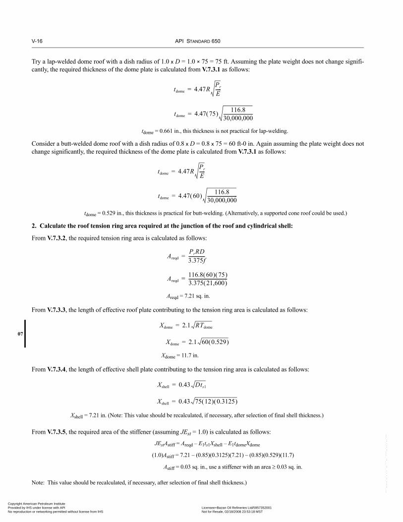
V-16 API STANDARD 650
07
Copyright AmProvided by No reproduc
-``,,,,,,`,,`,`,`,``,,````,,``-`-`,,`,,`,`,,`---
Try a lap-welded dome roof with a dish radius of 1.0 x D = 1.0 × 75 = 75 ft. Assuming the plate weight does not change signifi-cantly, the required thickness of the dome plate is calculated from V.7.3.1 as follows:
tdome = 0.661 in., this thickness is not practical for lap-welding.
Consider a butt-welded dome roof with a dish radius of 0.8 x D = 0.8 x 75 = 60 ft-0 in. Again assuming the plate weight does notchange significantly, the required thickness of the dome plate is calculated from V.7.3.1 as follows:
tdome = 0.529 in., this thickness is practical for butt-welding. (Alternatively, a supported cone roof could be used.)
2. Calculate the roof tension ring area required at the junction of the roof and cylindrical shell:
From V.7.3.2, the required tension ring area is calculated as follows:
Areqd = 7.21 sq. in.
From V.7.3.3, the length of effective roof plate contributing to the tension ring area is calculated as follows:
Xdome = 11.7 in.
From V.7.3.4, the length of effective shell plate contributing to the tension ring area is calculated as follows:
Xshell = 7.21 in. (Note: This value should be recalculated, if necessary, after selection of final shell thickness.)
From V.7.3.5, the required area of the stiffener (assuming JEst = 1.0) is calculated as follows:
JEstAstiff = Areqd – E1ts1Xshell – E1tdomeXdome
(1.0)Astiff = 7.21 – (0.85)(0.3125)(7.21) – (0.85)(0.529)(11.7)
Astiff = 0.03 sq. in., use a stiffener with an area ≥ 0.03 sq. in.
Note: This value should be recalculated, if necessary, after selection of final shell thickness.)
tdome 4.47RPr
E-----=
tdome 4.47 75( ) 116.830,000,000---------------------------=
tdome 4.47RPr
E-----=
tdome 4.47 60( ) 116.830,000,000---------------------------=
AreqdPrRD3.375f---------------=
Areqd116.8 60( ) 75( )3.375 21,600( )-----------------------------------=
Xdome 2.1 RTdome=
Xdome 2.1 60 0.529( )=
Xshell 0.43 Dts1=
Xshell 0.43 75 12( ) 0.3125( )=
erican Petroleum Institute IHS under license with API Licensee=Bazan Oil Refineries Ltd/5957352001
Not for Resale, 02/18/2008 23:53:18 MSTtion or networking permitted without license from IHS
-

WELDED STEEL TANKS FOR OIL STORAGE V-17
Copyright AmericaProvided by IHS uNo reproduction o
3. Check that buckling will occur elastically in the unstiffened cylindrical shell:
From V.8.1.1, elastic buckling will occur if the following equation is satisfied:
, thus buckling will be elastic.
Note: This value should be recalculated, if necessary, after selection of final shell thickness.)
4. Calculate the minimum shell thickness required for the combined loading from design external pressure and wind:
From V.8.1.3, the required minimum shell thickness is calculated as follows:
where
Ps = the greater of 1) the specified design external pressure excluding wind or 2) W + 0.4Pe, where W is the specified design wind pressure, lb/ft2,
Ps = 0.6 lb/in2 = 86.4 lb/ft2 or 31 + 0.4 (86.4) = 65.6 lb/ft2.
tavg ≥ 0.703 in.
5. Calculate the transformed shell height:
The required minimum thickness is greater than the available thickness and the shell must be stiffened.
6. Calculate the maximum spacing of intermediate stiffeners:
From V.8.2.1.2,
Hsafe = 5.84 ft
Course NumberActual Shell Course Height
(ft)Thickness
(in.)Transformed Shell Course Height *
(ft)1 8 0.3125 8.002 8 0.3125 8.003 8 0.3125 8.004 8 0.3125 8.005 8 0.328 7.096 8 0.395 4.45
Sum = 48 ft Sum = 43.54 ft* For example, the transformed height of No. 5 shell course = (0.3125/.328)2.5(8) = 7.09 ft (see V.8.1.4.b)
Dtsmin---------⎝ ⎠⎛ ⎞
0.75 HTS
D--------⎝ ⎠⎛ ⎞ Fy
E-----⎝ ⎠⎛ ⎞
0.5
0.00675≥
750.3125----------------⎝ ⎠⎛ ⎞
0.75 43.5475
-------------⎝ ⎠⎛ ⎞ 36
30,000----------------⎝ ⎠⎛ ⎞
0.5
1.23= 0.19≥
tsmin1.903 HTSPs( )0.4 D0.6
E( )0.4------------------------------------------------≥
tsmin1.903 43.54 86.4( )( )0.4 750.6
30,000,000( )0.4----------------------------------------------------------------≥
Hsafe0.2 tsmin( )2.5 E( )
D1.5 Ps( )-----------------------------------=
Hsafe0.2 0.3125( )2.5 30,000,000( )
75( )1.5 733.36( ) 86.4( )-----------------------------------------------------------------=
--``,,,,,,`,,`,`,`,``,,````,,``-`-`,,`,,`,`,,`---
n Petroleum Institute nder license with API Licensee=Bazan Oil Refineries Ltd/5957352001
Not for Resale, 02/18/2008 23:53:18 MSTr networking permitted without license from IHS
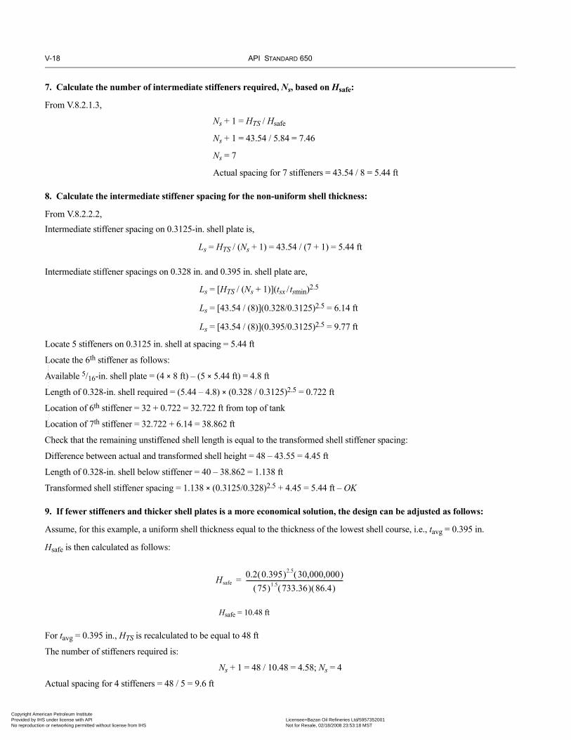
V-18 API STANDARD 650
Copyright AmProvided by No reproduc
7. Calculate the number of intermediate stiffeners required, Ns, based on Hsafe:
From V.8.2.1.3,
Ns + 1 = HTS / Hsafe
Ns + 1 = 43.54 / 5.84 = 7.46
Ns = 7
Actual spacing for 7 stiffeners = 43.54 / 8 = 5.44 ft
8. Calculate the intermediate stiffener spacing for the non-uniform shell thickness:
From V.8.2.2.2,Intermediate stiffener spacing on 0.3125-in. shell plate is,
Ls = HTS / (Ns + 1) = 43.54 / (7 + 1) = 5.44 ft
Intermediate stiffener spacings on 0.328 in. and 0.395 in. shell plate are,
Ls = [HTS / (Ns + 1)](tsx /tsmin)2.5
Ls = [43.54 / (8)](0.328/0.3125)2.5 = 6.14 ft
Ls = [43.54 / (8)](0.395/0.3125)2.5 = 9.77 ft
Locate 5 stiffeners on 0.3125 in. shell at spacing = 5.44 ft
Locate the 6th stiffener as follows:
Available 5/16-in. shell plate = (4 × 8 ft) – (5 × 5.44 ft) = 4.8 ft
Length of 0.328-in. shell required = (5.44 – 4.8) × (0.328 / 0.3125)2.5 = 0.722 ft
Location of 6th stiffener = 32 + 0.722 = 32.722 ft from top of tank
Location of 7th stiffener = 32.722 + 6.14 = 38.862 ft
Check that the remaining unstiffened shell length is equal to the transformed shell stiffener spacing:
Difference between actual and transformed shell height = 48 – 43.55 = 4.45 ft
Length of 0.328-in. shell below stiffener = 40 – 38.862 = 1.138 ft
Transformed shell stiffener spacing = 1.138 × (0.3125/0.328)2.5 + 4.45 = 5.44 ft – OK
9. If fewer stiffeners and thicker shell plates is a more economical solution, the design can be adjusted as follows:
Assume, for this example, a uniform shell thickness equal to the thickness of the lowest shell course, i.e., tavg = 0.395 in.
Hsafe is then calculated as follows:
Hsafe = 10.48 ft
For tavg = 0.395 in., HTS is recalculated to be equal to 48 ft
The number of stiffeners required is:
Ns + 1 = 48 / 10.48 = 4.58; Ns = 4
Actual spacing for 4 stiffeners = 48 / 5 = 9.6 ft
Hsafe0.2 0.395( )2.5 30,000,000( )
75( )1.5 733.36( ) 86.4( )--------------------------------------------------------------=
--``,,,,,,`,,`,`,`,``,,````,,``-`-`,,`,,`,`,,`---
erican Petroleum Institute IHS under license with API Licensee=Bazan Oil Refineries Ltd/5957352001
Not for Resale, 02/18/2008 23:53:18 MSTtion or networking permitted without license from IHS

WELDED STEEL TANKS FOR OIL STORAGE V-19
07
07
07
07
07
07
Copyright AmericaProvided by IHS uNo reproduction o
10. Calculate the number of buckling waves:From V.8.2.2.1,
11. Calculate the radial load on a circumferential stiffener placed 9.6 ft from the top of the shell.From V.8.2.2.3, the radial load is calculated as follows:
; where Ps = 86.4 lb/ft2
= 69.1 lb/in.
12. Calculate the total contributing shell width acting with the intermediate stiffener:From V.8.2.2.4,
; where tshell = 0.395 in.
; 16.0 in.
13. Calculate the required moment of inertia of the intermediate stiffener region:From V.8.2.2.5, the required moment of inertia is calculated as follows:
14. Calculate the total area required in the intermediate stiffener region:From V.8.2.2.6.1, the required area is calculated as follows:
N2 5.33D3
tsminLs2----------------- 100; Ls L1 L2+( ) 2⁄ 9.6 9.6+( ) 2⁄ 9.6ft.= = =≤=
N2 5.33 75( )3
0.395( ) 9.6( )2-------------------------------- 249 100; > N= > 10, therefore use 10.= =
QPsLs
12----------=
Q 86.4( ) 9.6( )12
---------------------------=
2 wshell× 2= 1.47 Dtshell×
2 1.47 75( ) 0.395( )×
Ireqd648QD3
E N2 1–( )-----------------------=
Ireqd648 69.1( ) 75( )3
30,000,000 100 1–( )-------------------------------------------------=
Ireqd 6.36 in.4=
Areqd6QD
f------------=
Areqd6 69.1( ) 75( )
14 400,( )-----------------------------=
Areqd 2.16 in.2=
--``,,,,,,`,,`,`,`,``,,````,,``-`-`,,`,,`,`,,`---
n Petroleum Institute nder license with API Licensee=Bazan Oil Refineries Ltd/5957352001
Not for Resale, 02/18/2008 23:53:18 MSTr networking permitted without license from IHS
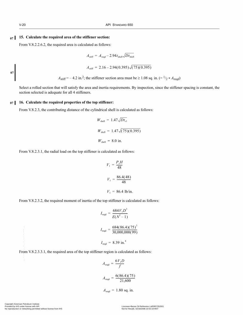
V-20 API STANDARD 650
07
07
07
Copyright AmProvided by No reproduc
15. Calculate the required area of the stiffener section:
From V.8.2.2.6.2, the required area is calculated as follows:
Astiff = – 4.2 in.2; the stiffener section area must be ≥ 1.08 sq. in. (= 1/2 × Areqd)
Select a rolled section that will satisfy the area and inertia requirements. By inspection, since the stiffener spacing is constant, thesection selected is adequate for all 4 stiffeners.
16. Calculate the required properties of the top stiffener:
From V.8.2.3, the contributing distance of the cylindrical shell is calculated as follows:
From V.8.2.3.1, the radial load on the top stiffener is calculated as follows:
From V.8.2.3.2, the required moment of inertia of the top stiffener is calculated as follows:
From V.8.2.3.3.1, the required area of the top stiffener region is calculated as follows:
Astiff Areqd 2.94tshell Dtshell–=
Astiff 2.16 2.94 0.395( ) 75( ) 0.395( )–=
Wshell 1.47 Dts1=
Wshell 1.47 75( ) 0.395( )=
Wshell 8.0 in.=
V1PsH48
---------=
V186.4 48( )
48---------------------=
V1 86.4 lb/in.=
Ireqd684V1D
3
E N2 1–( )-----------------------=
Ireqd684 86.4( ) 75( )3
30,000,000 99( )--------------------------------------=
Ireqd 8.39 in.4=
Areqd6V1D
f-------------=
Areqd6 86.4( ) 75( )
21,600-----------------------------=
Areqd 1.80 sq. in.=
--``,,,,,,`,,`,`,`,``,,````,,``-`-`,,`,,`,`,,`---
erican Petroleum Institute IHS under license with API Licensee=Bazan Oil Refineries Ltd/5957352001
Not for Resale, 02/18/2008 23:53:18 MSTtion or networking permitted without license from IHS

WELDED STEEL TANKS FOR OIL STORAGE V-21
Copyright AmericaProvided by IHS uNo reproduction o
--``,,,,,,`,,`,`,`,``,,````,,``-`-`,,`,,`,`,,`---
From V.8.2.3.3.2, the required area of the top stiffener section is calculated as follows:
Astiff = 1.80 – (0.85)(.395)(8.0) – (0.85)(0.529)(11.7) = –6.15 in. The stiffener section area must be ≥ 0.90 sq. in. (= 1/2 × Atotal)
Select a rolled section that will satisfy the area and inertia requirements.
17. Calculate the required properties of the bottom stiffener region:
From V.8.2.3, the contributing distance of the cylindrical shell is calculated as follows:
From V.8.2.3.2, the required moment of inertia of the bottom stiffener is calculated as follows:
From V.8.2.3.3.1, the required area of the bottom stiffener region is calculated as follows:
From V.8.2.3.3.2, the required area of the bottom stiffener section is calculated as follows:
Astiff = 1.80 – (0.85)(.395)(8.0) – (0.85)(0.375)(6.0) = –2.80 in.
The contributing portion of the shell-to-bottom joint has a calculated moment of inertia of 20.2 in.4 and will satisfy the area andinertia requirements. Thus, an additional stiffener is not necessary.
Astiff Areqd JEsts1Xshell– JErtdomeXdome–=
Wshell 1.47 Dtsn=
Wshell 1.47 75( ) 0.395( )=
Wshell 8.0 in.=
Ireqd684V1D3
E N2 1–( )-----------------------=
Ireqd684 86.4( ) 75( )3
30,000,000 99( )--------------------------------------=
Ireqd 8.39 in.4=
Areqd6V1D
f-------------=
Areqd6 86.4( ) 75( )
21,600-----------------------------=
Areqd 1.80 sq. in.=
Astiff Areqd JEstsnXshell– JEbtbXbtm–=
n Petroleum Institute nder license with API Licensee=Bazan Oil Refineries Ltd/5957352001
Not for Resale, 02/18/2008 23:53:18 MSTr networking permitted without license from IHS

V-22 API STANDARD 650
Copyright AmProvided by No reproduc
V.11 Technical Basis of This AppendixThe organization of this appendix was modeled after a proprietary DuPont Standard SG 11.4 S. API appreciates DuPont’s consentto utilize their standard as a model without any restriction or reservation to develop this appendix. The equations prescribed in thisappendix were generally extracted from the same proprietary standard and are based on the same fundamental equations fromvarious public domain references used to develop the proprietary standard. However, where appropriate, the nomenclature waschanged to be consistent with API Std 650. Some equations have been modified from the proprietary standard to be consistentwith API Std 650 safety factors or other design considerations. For example, some equations have been modified to be consistentwith Reference 2. Where necessary, equations have been added for consistency with API Std 650 design principles, such as incor-poration of the transformed shell method.
V.12 References1. DuPont Corporate Engineering Standard SG11.4S, Field Erected Storage Tank Design Procedures, Section 5, External Pres-
sure Design.
2. API Publication, Stability of API Standard 650 Tank Shells, Raymund V. McGrath.
3. The Structural Research Council (SSRC), Guide to Stability Design Criteria for Metal Structures, Section 14.3.5.
4. Code Case 2286, “Alternative Rules for Determining Allowable Compressive Stresses for Cylinders, Cones, Spheres and Formed Heads,” Cases of ASME Boiler and Pressure Vessel Code.
5. Welding Research Council Bulletin 406, “Proposed Rules for Determining Allowable Compressive Stresses for Cylinders, Cones, Spheres and Formed Heads,” C. D. Miller and K. Mokhtarian.
6. American Society of Mechanical Engineers (ASME) Boiler and Pressure Vessel Code, Section VIII, Division 1.
7. American Iron & Steel Institute (AISI) Publication, Steel Plate Engineering Data, Volume 2.
8. ASME Paper 65-MET-15, “Theoretical and Experimental Study of Steel Panels in Which Membrane Tension is Developed,” by J. S. McDermott.
9. Machine Design Magazine, December 9, 1976, “Stress Analysis of Pressurized Panels,” by J. A. Martinelli.
--``,,,,,,`,,`,`,`,``,,````,,``-`-`,,`,,`,`,,`---
erican Petroleum Institute IHS under license with API Licensee=Bazan Oil Refineries Ltd/5957352001
Not for Resale, 02/18/2008 23:53:18 MSTtion or networking permitted without license from IHS

•
••
•
07
•
Copyright AmericaProvided by IHS uNo reproduction o
APPENDIX W—COMMERCIAL AND DOCUMENTATION RECOMMENDATIONS
The following commercial and documentation recommendations apply to all tanks when specified by the Purchaser on the DataSheet.
W.1 Document Submittals and ReviewW.1.1 GENERAL
1. Technical documents listed below shall be submitted by the Manufacturer for review by the Purchaser at specified timesduring a project. Additional documents may be required and shall be a matter of agreement between the Purchaser and theManufacturer. Submittals and reviews shall be in accordance with contractual schedule agreements. All documents shall be inreproducible form agreeable to the Purchaser.
2. Unless specified otherwise by the Purchaser, the minimum required content of the technical documentation packages shallbe as described in this appendix.
W.1.2 QUOTATION OR BID DOCUMENT PACKAGE
1. All quotations shall be submitted in accordance with this Standard and Purchaser’s requirements listed in the Data Sheet. Inaddition, a second quotation containing alternates to Purchaser’s requirements may be quoted for Purchaser’s considerationprovided the alternates are clearly marked as such and are completely described in that bid.
2. The Manufacturer shall mark and return the Purchaser’s previously prepared Data Sheet. Some entries will not be deter-mined until completion of negotiations and/or completion of the detailed design. Such entries may remain blank for thissubmittal. The bid shall include the design wind speed and design snow load that will be used in the design by theManufacturer.
3. The Manufacturer shall provide a list of all engineered accessories being purchased from suppliers, indicating the Manu-facturer, and model or part number. Alternatively, when a specific Manufacturer is not known at the time of bidding, a list ofManufacturer-approved suppliers may be submitted. Excluded from the list requirement are commodities such as plate, pipe,flanges, and bolts. Included in the list are items such as floating roofs, dome roofs, roof seals, pressure vents, gauges, andinstrumentation. Also, see C.1.1.
W.1.3 DESIGN REVIEW DOCUMENT PACKAGES
Unless specified otherwise, a Purchaser’s review of Manufacturer’s design calculations and general arrangement drawings isrequired before the order of materials. Unless specified otherwise, the Purchaser’s review of the documents listed in Items 3through 7 below is required prior to the start of fabrication. Work may begin following conclusion of any negotiations generatedby the review process. A copy of the review packages with any annotations including nozzle size, orientations, projections, place-ment and elevations of ladders, platforms, stairs, and attachments, etc., shall be returned to the Manufacturer. The Manufacturershall promptly revise/update the drawings, calculations, and information on the Data Sheet showing all review-generatedchanges and shall submit copies to the Purchaser. The Design Review Document shall consist of at least the following:
1. Manufacturer’s design calculations as described in W.2 and structural loads for foundation design.
2. General arrangement drawings with complete material specification.
3. Detailed fabrication drawings.
4. Welding procedure specifications (WPSs) and procedure qualification records (PQRs). This shall include weld hardnesscriteria when required by the Purchaser. Review of duplicate weld procedures for multiple tanks is not required when writtenpermission is received from the Purchaser.
5. Heat treatment procedures (if required).
6. Nondestructive examination procedures and testing procedures.
7. Description of proposed test gaskets (see 4.9), including material properties, dimensions, and design characteristics.
--``,,,,,,`,,`,`,`,``,,````,,``-`-`,,`,,`,`,,`---
W-1
n Petroleum Institute nder license with API Licensee=Bazan Oil Refineries Ltd/5957352001
Not for Resale, 02/18/2008 23:53:18 MSTr networking permitted without license from IHS

W-2 API STANDARD 650
07
Copyright AmProvided by No reproduc
--``,,,,,,`,,`,`,`,``,,````,,``-`-`,,`,,`,`,,`---
W.1.4 INTERIM DOCUMENTS DURING CONSTRUCTION
The Manufacturer shall promptly submit revised documents describing any design or construction changes to the Purchaser. Cop-ies of Material Test Reports applicable to components listed in 4.2.9.1 shall be forwarded to the Purchaser upon receipt of thereports.
W.1.5 POST-CONSTRUCTION DOCUMENT PACKAGE
Upon completion of construction and testing, copies of a Manufacturer’s data book shall be supplied in the quantities specified inthe contract. Each copy shall contain at least the documents listed below:
1. Final general arrangement and detail fabrication drawings, marked “as-built” by the Manufacturer, complete with dimen-sions and data, with complete materials specification and parts list.
2. Design calculations described in W.2.
3. Copies of Material Test Reports applicable to shell plates and annular plates.
4. Reports of the results of all tests including weld hardness (when weld hardness criteria are specified), and reports of allnondestructive examinations. Radiographic films shall also be included. For tank pressure test data, include results andduration of pressure test(s), test water level, fill rate, imposed pneumatic pressure, hold times, drain rate, etc.
5. Shell and bottom elevation measurements for hydro-test.
6. Nameplate facsimile.
7. Manufacturer’s certification per Figure 10-2.
8. The Data Sheet reflecting as-built conditions.
9. A drawing that lists the following for each shell course:
a. The required shell thicknesses for both the design condition (including corrosion allowance) and the hydrostatic testcondition.
b. The nominal thickness used.c. The material specification.d. The allowable stresses.
10. Nominal thicknesses used for materials other than shell plates.
11. Handling criteria and rigging instructions (for shop-built tanks only).
W.2 Manufacturer’s CalculationsAll manual calculations shall include relevant formulas and source paragraphs in this Standard or in other specifications or engi-neering practices, values used in the formulas, calculated results, and acceptance criteria used. Where a computer program per-forms design calculations, a program description shall be given, including name and version of the program, program limitationsand assumptions used, and a brief description of what the program does. These calculations and/or computer programs shalladdress at least the following:
1. Determination of design thicknesses for all pressure boundary elements to satisfy all specified loading conditions, whichmay include contents, pressure, partial vacuum, dead loads, live loads, snow loads, rain loads, roof flotation, dike or floodplain partial submergence, wind, and seismic activity.
2. Overturning check and anchorage due to wind forces, seismic forces, and internal pressure, if applicable.
3. Seismic design requirements (e.g., base shear, longitudinal compression, sliding friction resistance checks, overturningmoment checks, and anchorage), if applicable.
4. Shell stability checks to determine whether shell stiffeners or increased shell course thicknesses will be required.
5. Unless specified otherwise by the Purchaser, whenever the tank diameter exceeds 36 m (120 ft), shell stiffness coefficients,maximum unrestrained radial deflection, angle of rotation of bottom course shell nozzles, and the nomographs formoments and forces that these nozzles can safely sustain from connected piping shall be provided in accordance with pro-
•
•
erican Petroleum Institute IHS under license with API Licensee=Bazan Oil Refineries Ltd/5957352001
Not for Resale, 02/18/2008 23:53:18 MSTtion or networking permitted without license from IHS

WELDED STEEL TANKS FOR OIL STORAGE W-3
•
•
07
•
Copyright AmericaProvided by IHS uNo reproduction o
--``,,,,,,`,,`,`,`,``,,````,,``-`-`,,`,,`,`,,`---
visions of Appendix P. Alternate analysis techniques, such as the finite element method, may also be used to satisfy thisrequirement.
6. Any additional calculations specified by the Purchaser to show compliance with this Standard and any appendices invoked.
W.3 Manufacturer’s Drawing ContentsAll Manufacturer’s drawings shall be thoroughly checked for accuracy and completeness before sending for Purchaser review.Manufacturer’s drawing(s) shall show, as a minimum, the following information:
1. An updated list of drawings for each tank shall be resubmitted each time drawings are revised and reissued.2. Identification of the storage tank as designated by the Purchaser.
3. Reference to applicable practices, standards, specifications, details, and associated drawings and sketches.
4. Materials of construction, designated corrosion allowance(s), and gasket specifications.
5. Extent of postweld heat treatments.
6. Extent of radiography to be applied to bottom, shell, and roof butt-welds.
7. Shell design joint efficiencies, for Appendices A, J, and S.
8. Complete details and dimensions of the tank, including external and internal attachments and appurtenances supplied byManufacturer and sub-contractors.
9. Bottom slope.
10. Nominal plate thicknesses for shell, roof, reinforcement, and bottom.
11. Location of all welded seams. All welds shall be either pictorially detailed or identified by use of the standard weldingsymbols of ANSI/AWS A2.4. Welding procedures shall be listed for each weld. A “weld map” may be used if it clearly indi-cates the weld procedure specification used for every joint.
12. For flanges other than those conforming to ASME B16.5 or ASME B16.47, and marked accordingly, show all dimensionsand finish of flange face.
13. Facsimile of nameplate with data to be stamped thereon with location and details of fabrication of nameplate bracket.
14. Empty, operating, and test weight of tank.
15. Loads on foundation as also shown on the Data Sheet, Line 13.
16. Foundation plans and construction details (if supplied by the Manufacturer or the sub-contractor).
W.4 Bids for Floating RoofsW.4.1 Bids for tanks having floating roofs shall contain sufficient engineering data, including material specifications for bothmetallic and non-metallic components, nominal thicknesses, and sufficient information (see C.3.4.1 and C.3.4.2 or H.2.1, asapplicable) to enable the Purchaser to verify that the bidder has considered all specified design requirements.
W.4.2 Manufacturer shall list in the quotation all roof accessories furnished and included in the base price of the roof. If anyaccessories are purchased from other suppliers, the Manufacturer shall provide that supplier’s name and the model or part number.
W.4.3 Manufacturer shall state the lowest and highest operating level of roof in the quotation.
W.4.4 Manufacturer shall clearly describe the extent of electrical grounding and shunts included as a part of the floating roofdesign.
W.4.5 Manufacturer shall provide a cross-section of all seals showing materials and complete details of construction with thebid.
W.4.6 The Manufacturer shall submit with the bid the minimum and the maximum allowable annular space between the roofand shell, as well as the maximum and minimum annular space the proposed roof seal system can accommodate.
W.4.7 Manufacturer shall specify size, number, and type of drains with the quotation (external roof only).
n Petroleum Institute nder license with API Licensee=Bazan Oil Refineries Ltd/5957352001
Not for Resale, 02/18/2008 23:53:18 MSTr networking permitted without license from IHS

W-4 API STANDARD 650
07
Copyright AmProvided by No reproduc
W.4.8 The bid shall state if a wind skirt, a top-shell extension, or overflows will be required for proper functioning of the roofseal (external roof only).
W.4.9 The Manufacturer of the external floating roof shall prepare and submit to the Purchaser the following calculations:
W.4.9.1 Calculations showing that the roof design complies with the buoyancy requirements of C.3.4.1a, for both single-deckand double-deck roofs using the smaller of the specific gravity in C.3.4.1 (0.7), or the minimum specific gravity of the productspecified on the Data Sheet, Line 5.
W.4.9.2 Calculations showing that the roof design complies with the punctured compartment loading condition for single-deckpontoon roofs and for double deck roofs as specified in C.3.4.1b.
W.4.9.3 Calculations showing that the design of the roof and roof supports satisfies C.3.10.2.
W.4.10 The Manufacturer of the internal floating roof shall prepare and submit to the Purchaser the following calculations,considering internal floating roof deflections and stresses for each of the load conditions required by Appendix H. All calculationsfor the floating condition shall be based upon the design specific gravity (per H.4.2.1.1).
W.4.10.1 Calculations showing that the roof design complies with the buoyancy requirements of H.4.2.1.
W.4.10.2 Calculations showing that the roof design complies with the punctured compartment loading condition for single-deck pontoon roofs and for double deck roofs as specified in H.4.2.3.
W.4.10.3 Calculations showing that the design of the roof and roof supports in the landed condition satisfies H.4.2.2.2.
W.4.11 The internal floating roof Manufacturer shall specify the internal floating roof weight and total flotation displacementprovided based on a flotation level for design specific gravity per H.4.2.1.
W.5 Jobsite ResponsibilitiesUnless otherwise specified by the Purchaser, the Manufacturer shall furnish all labor, tools, equipment, supplies, materials, utili-ties (including power for welding), storage, and personnel services necessary for, and reasonably incidental to, the delivery ofmaterials to the site, the construction of the tank(s), and the removal of surplus and scrap materials from the job site. See the DataSheet (see Line 14) for the Manufacturer’s additional post-hydro-test responsibilities. The Purchaser shall furnish and dispose ofthe water for hydro-testing the tank from the tie-in points as designated on the Data Sheet, Line 14.
•
•
--``,,,,,,`,,`,`,`,``,,````,,``-`-`,,`,,`,`,,`---
erican Petroleum Institute IHS under license with API Licensee=Bazan Oil Refineries Ltd/5957352001
Not for Resale, 02/18/2008 23:53:18 MSTtion or networking permitted without license from IHS

Invoice To (❏ Check here if same as “Ship To”)
Name:
Title:
Company:
Department:
Address:
City: State/Province:
Zip/Postal Code: Country:
Telephone:
Fax:
E-Mail:
❏ Payment Enclosed ❏ P.O. No. (Enclose Copy)
❏ Charge My IHS Account No.
❏ VISA ❏ MasterCard ❏ American Express ❏ Diners Club ❏ Discover
Credit Card No.:
Print Name (As It Appears on Card):
Expiration Date:
Signature:
Quantity Product Number Title Total
Subtotal
Applicable Sales Tax (see below)
Rush Shipping Fee (see below)
Shipping and Handling (see below)
Total (in U.S. Dollars)
★ To be placed on Standing Order for future editions of this publication,place a check mark in the SO column and sign here:
Pricing and availability subject to change without notice.
Date:
SO★ Unit Price
❏ API Member (Check if Yes)
Ship To (UPS will not deliver to a P.O. Box)
Name:
Title:
Company:
Department:
Address:
City: State/Province:
Zip/Postal Code: Country:
Telephone:
Fax:
E-Mail:
Mail Orders – Payment by check or money order in U.S. dollars is required except for established accounts. State and local taxes, $10 processing fee, and 5% shipping mustbe added. Send mail orders to: API Publications, IHS, 15 Inverness Way East, c/o Retail Sales, Englewood, CO 80112-5776, USA.Purchase Orders – Purchase orders are accepted from established accounts. Invoice will include actual freight cost, a $10 processing fee, plus state and local taxes.Telephone Orders – If ordering by telephone, a $10 processing fee and actual freight costs will be added to the order.Sales Tax – All U.S. purchases must include applicable state and local sales tax. Customers claiming tax-exempt status must provide IHS with a copy of their exemptioncertificate.Shipping (U.S. Orders) – Orders shipped within the U.S. are sent via traceable means. Most orders are shipped the same day. Subscription updates are sent by First-ClassMail. Other options, including next-day service, air service, and fax transmission are available at additional cost. Call 1-800-854-7179 for more information.Shipping (International Orders) – Standard international shipping is by air express courier service. Subscription updates are sent by World Mail. Normal delivery is 3-4 daysfrom shipping date.Rush Shipping Fee – Next Day Delivery orders charge is $20 in addition to the carrier charges. Next Day Delivery orders must be placed by 2:00 p.m. MST to ensure overnightdelivery.Returns – All returns must be pre-approved by calling the IHS Customer Service Department at 1-800-624-3974 for information and assistance. There may be a 15% restock-ing fee. Special order items, electronic documents, and age-dated materials are non-returnable.
Effective January 1, 2007.API Members receive a 30% discount where applicable.The member discount does not apply to purchases made for the purpose of resale or for incorporation into commercial products, training courses, workshops, or othercommercial enterprises.
Available through IHS:Phone Orders: 1-800-854-7179 (Toll-free in the U.S. and Canada)
303-397-7956 (Local and International)Fax Orders: 303-397-2740Online Orders: global.ihs.com
2007 PublicationsOrder Form
Copyright American Petroleum Institute Provided by IHS under license with API Licensee=Bazan Oil Refineries Ltd/5957352001
Not for Resale, 02/18/2008 23:53:18 MSTNo reproduction or networking permitted without license from IHS
--``,,,,,,`,,`,`,`,``,,````,,``-`-`,,`,,`,`,,`---

There’s more where thiscame from.
The American Petroleum Institute provides additional resources and programs to the oil and natural gas industry which are based on API® Standards. For moreinformation, contact:
• API Monogram® Licensing Program Phone: 202-962-4791Fax: 202-682-8070
• American Petroleum Institute Quality Registrar Phone: 202-962-4791(APIQR®) Fax: 202-682-8070
• API Spec Q1® Registration Phone: 202-962-4791Fax: 202-682-8070
• API Perforator Design Registration Phone: 202-962-4791Fax: 202-682-8070
• API ISO/TS 29001 Registration Phone: 202-962-4791Fax: 202-682-8070
• API Training Provider Certification Program Phone: 202-682-8490Fax: 202-682-8070
• Individual Certification Programs Phone: 202-682-8064Fax: 202-682-8348
• Engine Oil Licensing and Certification System (EOLCS) Phone: 202-682-8516Fax: 202-962-4739
• API PetroTEAM™ (Training, Education and Meetings) Phone: 202-682-8195Fax: 202-682-8222
Check out the API Publications, Programs, and Services Catalog online at www.api.org.
Helping You Get The Job Done Right.®
Copyright American Petroleum Institute Provided by IHS under license with API Licensee=Bazan Oil Refineries Ltd/5957352001
Not for Resale, 02/18/2008 23:53:18 MSTNo reproduction or networking permitted without license from IHS
--``,,,,,,`,,`,`,`,``,,````,,``-`-`,,`,,`,`,,`---

06/07
Copyright American Petroleum Institute Provided by IHS under license with API Licensee=Bazan Oil Refineries Ltd/5957352001
Not for Resale, 02/18/2008 23:53:18 MSTNo reproduction or networking permitted without license from IHS
--``,,,,,,`,,`,`,`,``,,````,,``-`-`,,`,,`,`,,`---
Product No. C65011Copyright American Petroleum Institute Provided by IHS under license with API Licensee=Bazan Oil Refineries Ltd/5957352001
Not for Resale, 02/18/2008 23:53:18 MSTNo reproduction or networking permitted without license from IHS
--``,,,,,,`,,`,`,`,``,,````,,``-`-`,,`,,`,`,,`---