6-main prjct report
DESCRIPTION
its the main report of steering projectTRANSCRIPT

1
CHAPTER 1
DESCRIPTION
The Segway PT is a two-wheeled, self-balancing, battery-powered electric vehicle invented by
Dean Kamen. It is produced by Segway Inc. of New Hampshire, USA. The name Segway is a
homophone of the word segue, meaning smooth transition. PT is an abbreviation for personal
transporter. Computers and motors in the base of the device keep the Segway PT upright when
powered on with balancing enabled. A user commands the Segway to go forward by shifting
their weight forward on the platform and backward by shifting their weight backward. The
Segway detects, as it balances, the change in its center of mass, and first establishes and then
maintains a corresponding speed, forward or backward. Gyroscopic sensors and fluid-based
leveling sensors detect the weight shift. To turn, the user presses the handlebar to the left or the
right. Segway PTs are driven by electric motors and can reach a speed of 12.5 miles per hour
(20.1 km/h).
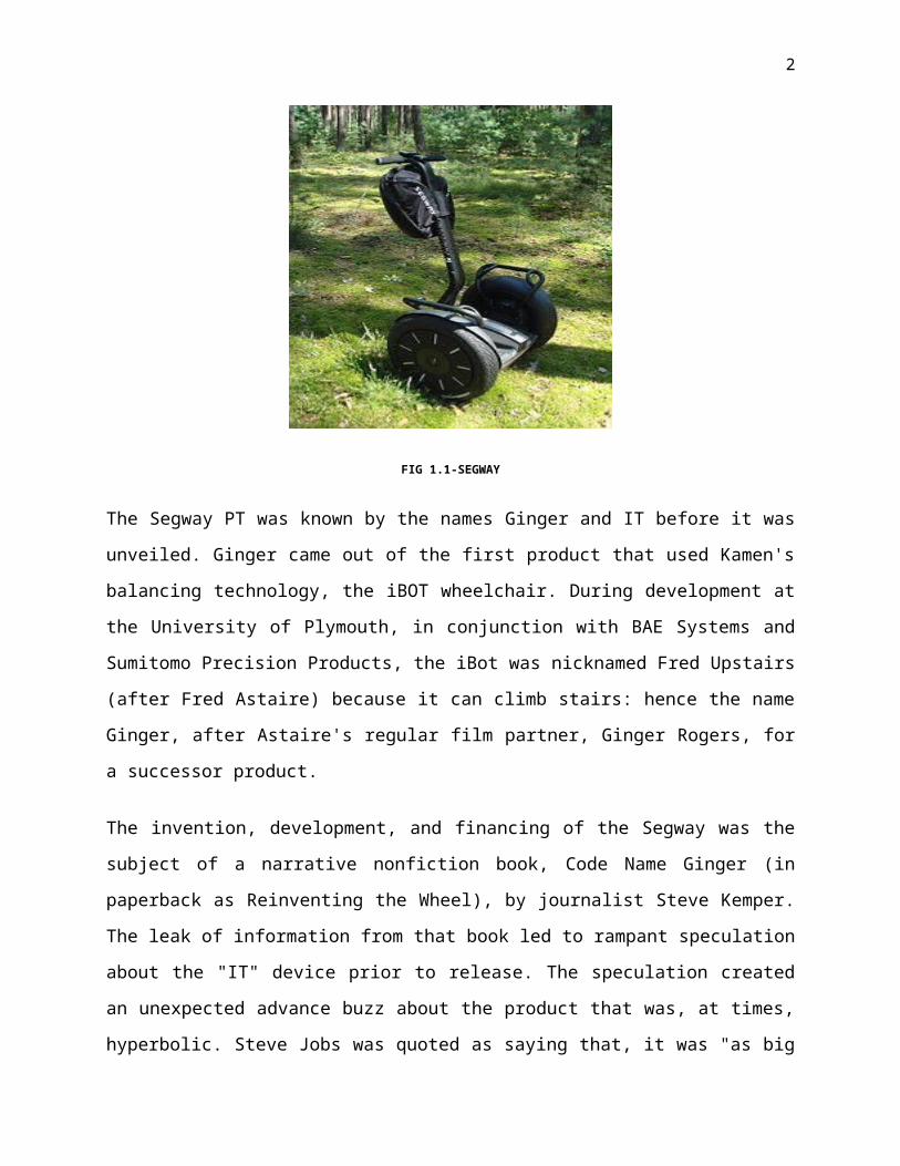
FIG 1.1-SEGWAY
The Segway PT was known by the names Ginger and IT before it was unveiled. Ginger came out
of the first product that used Kamen's balancing technology, the iBOT wheelchair. During
development at the University of Plymouth, in conjunction with BAE Systems and Sumitomo
2
Precision Products, the iBot was nicknamed Fred Upstairs (after Fred Astaire) because it can
climb stairs: hence the name Ginger, after Astaire's regular film partner, Ginger Rogers, for a
successor product.
The invention, development, and financing of the Segway was the subject of a narrative
nonfiction book, Code Name Ginger (in paperback as Reinventing the Wheel), by journalist
Steve Kemper. The leak of information from that book led to rampant speculation about the "IT"
device prior to release. The speculation created an unexpected advance buzz about the product
that was, at times, hyperbolic. Steve Jobs was quoted as saying that, it was "as big a deal as the
PC", though later sources quoted him as saying when first introduced to the product that its
design "sucked". John Doerr speculated that it would be more important than the Internet.
Articles were written in major publications speculating on it being a Sterling engine. South Park
devoted an episode to making fun of the hype before the product was released.
The product was unveiled 3 December 2001, in Bryant Park, the privately managed public park
located in the New York City borough of Manhattan, on the ABC News morning program Good
Morning America.

3
CHAPTER 2
FOOT STEP POWER GENERATION
Human-powered transport has been in existence since time immemorial in the form of walking,
running and swimming. However modern technology has led to machines to enhance the use of
human-power in more efficient manner. In this context, pedal power is an excellent source of
energy and has been in use since the nineteenth century making use of the most powerful
muscles in the body. Ninety-five percent of the exertion put into pedal power is converted into
energy. Pedal power can be applied to a wide range of jobs and is a simple, cheap, and
convenient source of energy. However, human kinetic energy can be useful in a number of ways
but it can also be used to generate electricity based on different approaches and many
organizations are already implementing human powered technologies to generate electricity to
power small electronic appliances.
Free play Energy Company (USA) has released a human-powered electricity generator for
commercial sale in which power is generated by pushing up and down with foot on a step-action
treadle. A similar, newly released portable energy source is a foot-powered device that allows
individuals to pump out power at a 40-watt clip to charge its own internal battery, which is
capable of providing a powerful jolt to car batteries and AC and DC devices. In another
approach, if everyone had small magnets in their shoes and the paving slabs had inter-connected
coils cast inside, all linked to batteries, electricity can be generated and the amount will depend
on how many people are on the move. A few months back there was also news in the country’s
news papers that some engineer (s) are planning and developing system to harness the energy of
vehicle locomotion on the roads .
Working on the idea to harness human locomotion power, MIT (USA) architecture students
James Graham and Thaddeus Jusczyk recently unveiled what they're calling the "Crowd Farm," a
setup that would derive energy from pounding feet in crowded places. This technology is a
proposal to harness human power as a source of sustainable energy. Population of India and
mobility of its masses will turn into boon in generating electricity from its (population’s)
footsteps. Human locomotion in over crowded subway stations, railway stations, bus stands,
airports, temples or rock concerts thus can be converted to electrical energy with the use of this
promising technology.

4
The technology would turn the mechanical energy of people walking or jumping into a source of
electricity. The students' test case, displayed at the Venice Biennale and in a train station in
Torino, Italy, was a prototype stool that exploits the passive act of sitting to generate power. The
weight of the body on the seat causes a flywheel to spin, which powers a dynamo that, in turn,
lights four LEDs. In each case, there would be a sub-flooring system consisting of independent
blocks. When people walk across this surface, the forces they impart will cause the blocks to slip
slightly, and a dynamo would convert the energy in those movements into electric current.
Students say that moving from this Proof-of-concept device to a large-scale Crowd Farm would
be expensive, but it certainly sounds a great option.
WORKING PRINCIPLE:
When a human steps on the device due to his/her body weight the iron plate moves downwards
and drives the crank shaft which further drives the gear arrangements; which further drives the
another crank shaft.
This crank shaft then moves the magnet in “to and fro” motion into a coil. When the magnet
moves into the hollow sections of the coil by the “FARADAYS LAWS OF ELECTRO
MAGNETIC INDUCTION” current flows through the copper wires which is AC by nature. A
rectifier circuit used to convert it to DC and finally fed to battery for storing the generated power.

5
CHAPTER 3
MANUFACTURING OF SEGWAY:
There are 3 steps in manufacturing of Segway. They are
1. Selection of material
2. Design
3. Machining process
4. Fabrication process
3.1 SELECTION OF MATERIAL:
Main components of Segway are
1. Frame2. piezoelectric sensor 3. Battery4. Dc Motor5. Chain drive
a. Sprocketb. Chain
6. 2 wheelsIn this project, we have used alloy 1018 mild steel material for fabricating frame of the segway.
1018 Mild Steel:
Alloy 1018 is the most commonly available of the cold-rolled steels. It is generally available in
round rod, square bar, and rectangle bar. It has a good combination of all of the typical traits of
steel - strength, some ductility, and comparative ease of machining. Chemically, it is very similar
to A36 Hot Rolled steel, but the cold rolling process creates a better surface finish and better
properties.
6
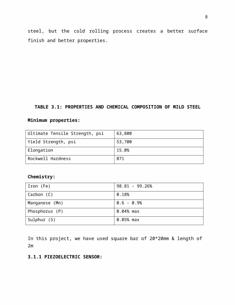
TABLE 3.1: PROPERTIES AND CHEMICAL COMPOSITION OF MILD STEEL
Minimum properties:
Ultimate Tensile Strength, psi 63,800
Yield Strength, psi 53,700
Elongation 15.0%
Rockwell Hardness B71
Chemistry:
Iron (Fe) 98.81 - 99.26%
Carbon (C) 0.18%
Manganese (Mn) 0.6 - 0.9%
Phosphorus (P) 0.04% max
Sulphur (S) 0.05% max
In this project, we have used square bar of 20*20mm & length of 2m
3.1.1 PIEZOELECTRIC SENSOR:
A piezoelectric sensor is a device that uses the piezoelectric effect to measure pressure,
acceleration, strain or force by converting them to an electrical signal.
When a crystal of dielectrics is given a mechanical stress, then small magnitude of current
isproduced. This effect is called Piezoelectric effect.
Piezoelectric sensors have proven to be versatile tools for the measurement of various processes.
They are used for quality assurance, process control and for research and development in many
different industries it was only in the 1950s that the piezoelectric effect started to be used for
industrial sensing applications. Since then, this measuring principle has been increasingly used
and can be regarded as a mature technology with an outstanding inherent reliability. It has been
successfully used in various applications, such as in medical, aerospace, nuclear instrumentation,
and as a pressure sensor in the touch pads of mobile phones. In the automotive industry,
piezoelectric elements are used to monitor combustion when developing internal combustion
engines. The sensors are either directly mounted into additional holes into the cylinder head or
the spark/glow plug is equipped with a built in miniature piezoelectric sensor.

7
FIG 3.1- PIEZOELECTRIC CRYSTAL PLATE
The rise of piezoelectric technology is directly related to a set of inherent advantages. The high
modulus of elasticity of many piezoelectric materials is comparable to that of many metals and
goes up to 10e6 N/m² Even though piezoelectric sensors are electromechanical systems that react
to compression, the sensing elements show almost zero deflection. This is the reason why
piezoelectric sensors are so rugged, have an extremely high natural frequency and an excellent
linearity over a wide amplitude range. Additionally, piezoelectric technology is insensitive to
electromagnetic fields and radiation, enabling measurements under harsh conditions. Some
materials used (especially gallium phosphate or tourmaline) have an extreme stability even at
high temperature, enabling sensors to have a working range of up to 1000°C. Tourmaline shows
pyro electricity in addition to the piezoelectric effect; this is the ability to generate an electrical
signal when the temperature of the crystal changes. This effect is also common to piezo ceramic
materials.
One disadvantage of piezoelectric sensors is that they cannot be used for truly static
measurements. A static force will result in a fixed amount of charges on the piezoelectric
material. While working with conventional readout electronics, imperfect insulating materials,
and reduction in internal sensor resistance will result in a constant loss of electrons, and yield a
decreasing signal.
8
FIG 3.2-PIEZOELECTRIC SENSOR TESTING
Elevated temperatures cause an additional drop in internal resistance and sensitivity. The main
effect on the piezoelectric effect is that with increasing pressure loads and temperature, the
sensitivity is reduced due to twin-formation. While quartz sensors need to be cooled during
measurements at temperatures above 300°C, special types of crystals like GaPO4 gallium
phosphate do not show any twin formation up to the melting point of the material itself.
3.1.2 BATTERY:
Battery (electricity), an array of electrochemical cells for electricity storage, either individually
linked or individually linked and housed in a single unit. An electrical battery is a combination of
one or more electrochemical cells, used to convert stored chemical energy into electrical energy.
Batteries may be used once and discarded, or recharged for years as in standby power
applications. Miniature cells are used to power devices such as hearing aids and wristwatches;
larger batteries provide standby power for telephone exchanges or computer data centers
FIG 3.3- BATTERY

9
Lead-acid batteries are the most common in PV systems because their initial cost is lower and
because they are readily available nearly everywhere in the world. There are many different sizes
and designs of lead-acid batteries, but the most important designation is that they are deep cycle
batteries. Lead-acid batteries are available in both wet-cell (requires maintenance) and sealed no-
maintenance versions.
Lead acid batteries are reliable and cost effective with an exceptionally long life. The Lead acid
batteries have high reliability because of their ability to withstand overcharge, over discharge
vibration and shock. The use of special sealing techniques ensures that our batteries are leak
proof and non-spoilable. The batteries have exceptional charge acceptance, large electrolyte
volume and low self-discharge, Which make them ideal as zero- maintenance batteries lead acid
batteries
Are manufactured/ tested using CAD (Computer Aided Design). These batteries are used in
Inverter & UPS Systems and have the proven ability to perform under extreme conditions. The
batteries have electrolyte volume, use PE Separators and are sealed in sturdy containers, which
give them excellent protection against leakage and corrosion.
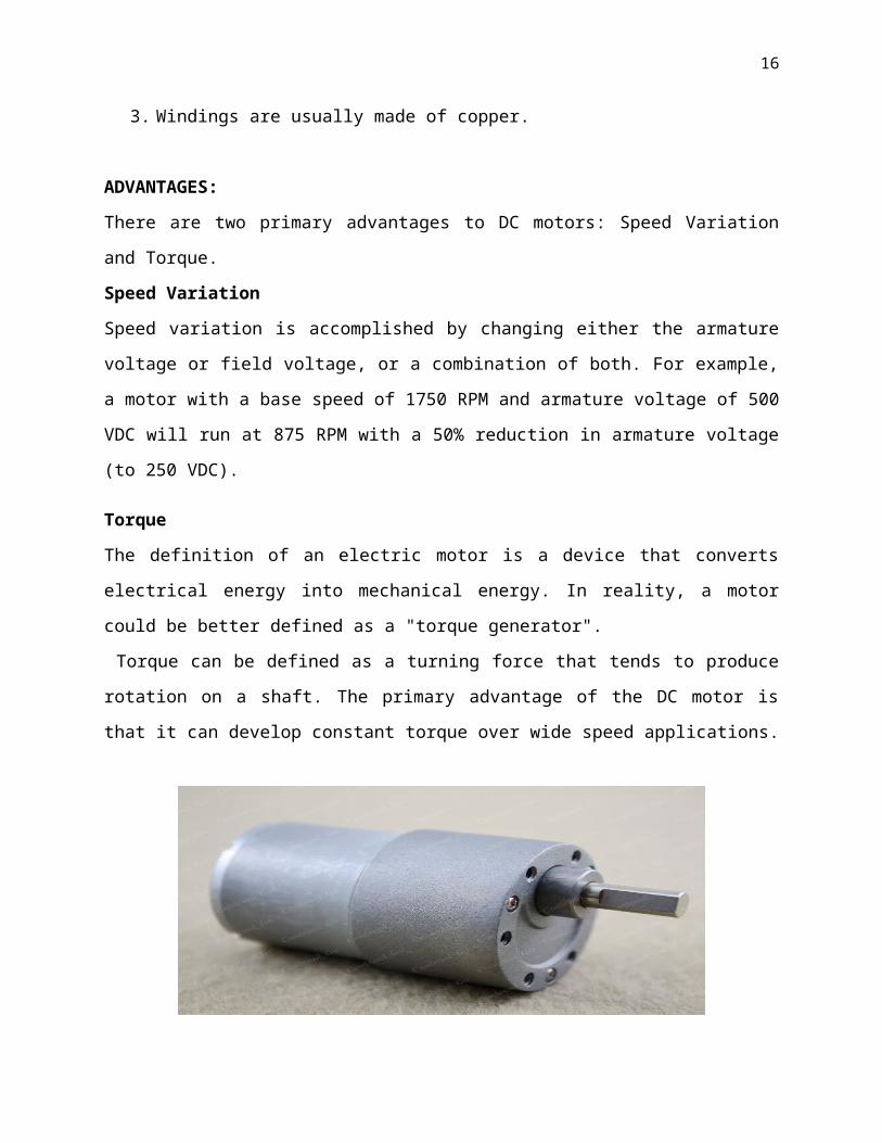
3.1.3 DC MOTORS:
Motors take electrical energy and produce mechanical energy. Electric motors are used to power
hundreds of devices we use in everyday life. Motors come in various sizes. Huge motors that can
take loads of 1000’s of Horsepower are typically used in the industry. Some examples of large
motor applications include elevators, electric trains, hoists, and heavy metal rolling mills.
Examples of small motor applications include motors used in automobiles, robots, hand power
tools and food blenders. Micro-machines are electric machines with parts the size of red blood
cells, and find many applications in medicine.
Electric motors are broadly classified into two different categories: DC (Direct Current) and AC
(Alternating Current). Within these categories are numerous types, each offering unique abilities
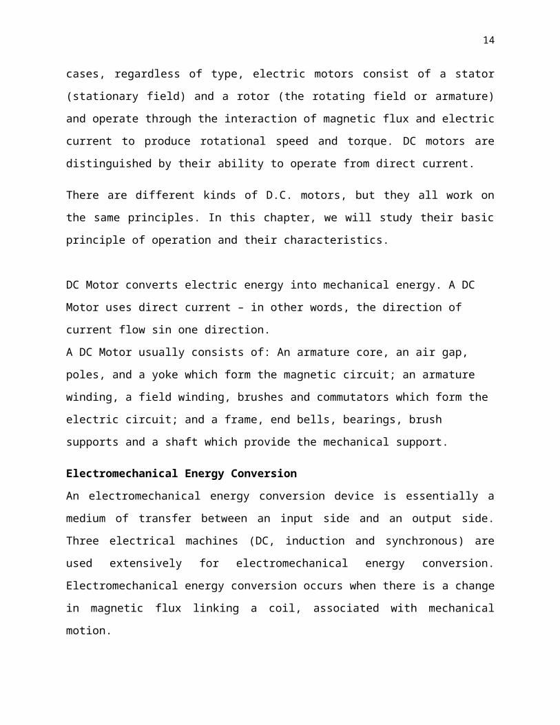
that suit them well for specific applications. In most cases, regardless of type, electric motors
consist of a stator (stationary field) and a rotor (the rotating field or armature) and operate
through the interaction of magnetic flux and electric current to produce rotational speed and
torque. DC motors are distinguished by their ability to operate from direct current.

10
There are different kinds of D.C. motors, but they all work on the same principles. In this
chapter, we will study their basic principle of operation and their characteristics.
DC Motor converts electric energy into mechanical energy. A DC Motor uses direct current – in
other words, the direction of current flow sin one direction.
A DC Motor usually consists of: An armature core, an air gap, poles, and a yoke which form the
magnetic circuit; an armature winding, a field winding, brushes and commutators which form the
electric circuit; and a frame, end bells, bearings, brush supports and a shaft which provide the
mechanical support.
Electromechanical Energy Conversion
An electromechanical energy conversion device is essentially a medium of transfer between an
input side and an output side. Three electrical machines (DC, induction and synchronous) are
used extensively for electromechanical energy conversion. Electromechanical energy conversion
occurs when there is a change in magnetic flux linking a coil, associated with mechanical
motion.
Construction
DC motors consist of one set of coils, called armature winding, inside another set of coils or a set
of permanent magnets, called the stator. Applying a voltage to the coils produces a torque in the
armature, resulting in motion.
Stator
1. The stator is the stationary outside part of a motor.
2. The stator of a permanent magnet dc motor is composed of two or more permanent
magnet pole pieces.
3. The magnetic field can alternatively be created by an electromagnet. In this case, a DC
coil (field winding) is wound around a magnetic material that forms part of the stator.
Rotor
1. The rotor is the inner part which rotates.
2. The rotor is composed of windings (called armature windings) which are connected to the
external circuit through a mechanical commutator.
3. Both stator and rotor are made of ferromagnetic materials. The two are separated by air-
gap.

11
Winding
A winding is made up of series or parallel connection of coils.
1. Armature winding - The winding through which the voltage is applied or induced.
2. Field winding - The winding through which a current is passed to produce flux (for the
electromagnet)
3. Windings are usually made of copper.
ADVANTAGES:
There are two primary advantages to DC motors: Speed Variation and Torque.
Speed Variation
Speed variation is accomplished by changing either the armature voltage or field voltage, or a
combination of both. For example, a motor with a base speed of 1750 RPM and armature voltage
of 500 VDC will run at 875 RPM with a 50% reduction in armature voltage (to 250 VDC).
Torque
The definition of an electric motor is a device that converts electrical energy into mechanical
energy. In reality, a motor could be better defined as a "torque generator".
Torque can be defined as a turning force that tends to produce rotation on a shaft. The primary
advantage of the DC motor is that it can develop constant torque over wide speed applications.
FIG 3.4-DC MOTOR
Specifications of dc motor:
Voltage-12volts
RPM- 10rpm

12
3.1.4 CHAIN DRIVE:
Chain drive is a way of transmitting mechanical power from one place to another. It is often used
to convey power to the wheels of a vehicle, particularly bicycles and motorcycles. It is also used
in a wide variety of machines besides vehicles.
Most often, the power is conveyed by a roller chain, known as the drive chain or transmission
chain, passing over a sprocket gear, with the teeth of the gear meshing with the holes in the links
of the chain. The gear is turned, and this pulls the chain putting mechanical force into the system.
Sometimes the power is output by simply rotating the chain, which can be used to lift or drag
objects. In other situations, a second gear is placed and the power is recovered by attaching
shafts or hubs to this gear. Though drive chains are often simple oval loops, they can also go
around corners by placing more than two gears along the chain; gears that do not put power into
the system or transmit it out are generally known as idler-wheels.
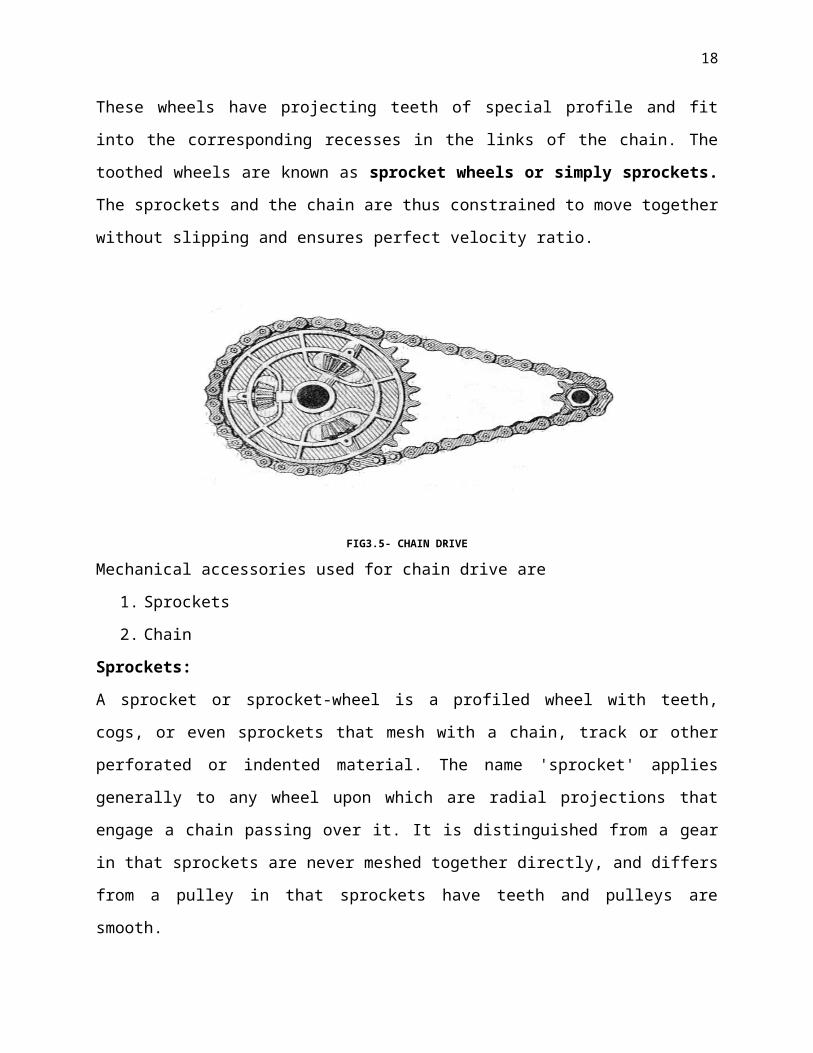
The chains are made up of number of rigid links which are hinged together by pin joints in order
to provide the necessary flexibility for wrapping round the driving and driven wheels. These
wheels have projecting teeth of special profile and fit into the corresponding recesses in the links
of the chain. The toothed wheels are known as sprocket wheels or simply sprockets. The
sprockets and the chain are thus constrained to move together without slipping and ensures
perfect velocity ratio.
FIG3.5- CHAIN DRIVE

13
Mechanical accessories used for chain drive are
1. Sprockets
2. Chain
Sprockets:
A sprocket or sprocket-wheel is a profiled wheel with teeth, cogs, or even sprockets that mesh
with a chain, track or other perforated or indented material. The name 'sprocket' applies generally
to any wheel upon which are radial projections that engage a chain passing over it. It is
distinguished from a gear in that sprockets are never meshed together directly, and differs from a
pulley in that sprockets have teeth and pulleys are smooth.
Two sizes of sprockets used in this project.
FIG 3.6-CHAIN SPROCKETS USED
Chain:
A chain is a series of connected links which are typically made of metal. A chain may consist of
two or more links. These are designed for transferring power in machines has links designed to
mesh with the teeth of the sprockets of the machine, and are flexible in only one dimension.
They are known as roller chains, though there are also non-roller chains such as block chain.
Roller chain or bush roller chain is the type of chain drive most commonly used for transmission
of mechanical power on many kinds of domestic, industrial and agricultural machinery,
14
including conveyors, wire- and tube-drawing machines, printing presses, cars, motorcycles, and
bicycles. It consists of a series of short cylindrical rollers held together by side links. It is driven
by a toothed wheel called a sprocket. It is a simple, reliable, and efficient means of power
transmission.
FIG 3.7-CHAIN
3.1.5 WHEELS:
The wheel is a device that enables efficient movement of an object across a surface where there
is a force pressing the object to the surface. A wheel is a circular component that is intended to
rotate on an axial bearing. The wheel is one of the main components of the wheel and axle which
is one of the six simple machines. Wheels, in conjunction with axles, allow heavy objects to be
moved easily facilitating movement or transportation while supporting a load, or performing
labor in machines. Wheels are also used for other purposes, such as a ship's wheel, steering
wheel, potter's wheel and flywheel.
Common examples are found in transport applications. A wheel greatly reduces friction by
facilitating motion by rolling together with the use of axles. In order for wheels to rotate, a
moment needs to be applied to the wheel about its axis, either by way of gravity, or by the
application of another external force or torque.
Based on our motor torque/speed characteristics, we needed to use relatively small wheels to get
adequate performance. We chose 12.5” pneumatic wheels made because they were inexpensive,

15
light, and had the 5/8” keyed hub we needed. We have used 2 wheels of same size in this project.
FIG 3.8- WHEELS
3.1.6 HANDLE BAR
The handlebar was supposed to be the easy part…until the decision to go for lean steering.
Aside from that part, it is just a piece of 80/209 1”x2” extrusion. This stuff is great because it
allows easy adjustment via sliding t-nuts, making height and angle modifications simple. We cut
a few custom brackets for it on the water jet out of the left-over aluminium from the base
plate .As for the lean-steering joint, we went through a bunch of iterations, including one with a
combination of compression and tension springs that sounded like an old Buick suspension. The
current design uses four strips of ¼” polycarbonate as leaf springs to center the steering joint.
The forward/backward rigidity of the joint is workable, but not great and is something to look at
for future modification
3.2 MECHANICAL DESIGN
Frame:
The major constraints on the frame design were weight and component accommodation. To deal
with the issue of weight, aluminum was selected as the primary construction material.
Aluminums low cost, high strength to weight ratio, availability, and versatility in joining made it
the right choice. The selected aluminum pieces were hollow aluminum tubing. It was originally
planned that the pieces be joined, after experimentation it was determined to be too difficult and
time consuming. The process would be successful, however the high cost made it unattainable.
The final joining choice ended up being the use of a brazing, or high temperature soldering
process, using #31 Aladdin 3-in-1 rods. The soldering proved to be the best joining method.
16
The size and shape of the frame was based upon the essential internal components. These
components included motors, encoders, the 8051 board, and the gyroscope. After construction
of the frame it was discovered that the thickness of the tubing was overlooked. As a result of the
problem the initial design of the 8051 board placement had to be changed. The end result was the
8051 board was placed on the underneath of the frame.
FIG 3.9-FRAME ISOMETRIC
Wheels:
The wheels were designed to carry the load of the robot itself and a mass placed atop. The
purpose of building the wheels was to cut down on cost as well as the weight of the cart. The
wheels were designed to the maximum allowable diameter of 6 in. The reason for the larger
wheels was for component placement purposes. With larger wheels more of the components
were able to be placed under the axles, thereby lowering the center of mass of the cart. With a
lower center of mass the balancing of the cart would occur more naturally.

17
FIG 3.10: WHEEL ISOMETRIC
Motors:
The motors chosen were 5 volt gear motor. There was an initial issue with selecting a 5 volt
motor, the amount of torque that it produced. The motor selected had a 120:1 gear ratio, with the
added torque of the internal gears the motors were expected to turn the wheels without any
problems. Another positive aspect to those motors became apparent in the mass calculation.
Each motor had a mass of 20 grams. The motors were expected to account for a large proportion
of the overall mass initially. However, the use of the motors below left more room for added
mass in other areas. A sketch of the motor is shown in Figure 1.1-3 below.
FIG 3.11-MOTOR ISOMETRIC
18
8051 Board:
Initially the 8051 board was to be placed on the inside of the front plate. However with the
design overlook the board didn’t fit. Also with the board placed on front the balancing function
would have become more complex, due to the cart being top end heavy. The alternative was
placing the 8051 board underneath the bottom plate of the robot. Positioning the 8051 board
underneath the bottom plate allowed for easy access to wiring, connecting the serial cable, and
resetting the 8051 board. The 8051 board being placed under the wheel axles also lowered the
center of mass of the robot.
Gyroscope:
The gyroscope was created using a potentiometer, a DC motor, and a hanging mass. The
hanging mass consisted of a plastic arm, a 3-volt DC motor, and a disk attached to the motor
shaft. The arm was attached to the potentiometer with the DC motor secured into it. The
spinning disk was a plastic gear with a steel washer epoxied to it. The spinning disk was
designed to counter the initial acceleration of the robot. As the robot tilted, the potentiometer
measured the change in voltage. An assembly of the gyroscope can be seen if Figure 3.13
FIG 3.12-GYROSCOPE DESIGN

19
Encoder Brackets:
The brackets used to hold the encoders were made of aluminum. One small sheet of aluminum
was cut into strips and then bent by hand to achieve the desired shape. The brackets were
important because they allowed the axles to have a sturdy support. The added support was
important because any bending could have caused large changes in the Segways motion. Also if
the shafts had been bent it could have caused increased friction resulting in insufficient torque.
The brackets also allowed easy mounting of the gyroscope. The brackets were simply mounted
to the plastic shaft supports by rivets. The brackets can be seen in Figure 1.1-5.
FIG 3.13 ENCODER BRACKET SETUP
Battery Placement:
The batteries were placed on the bottom plate of the robot to keep the center of mass of the robot
as low as possible. The batteries were also positioned so that the mass was evenly distributed on
the robot. The batteries were also kept clear of the swaying gyroscope in the middle of the
frame.

20
Top Plate:
The top plate was designed to be load bearing, as well as to enclose the entire robot. It was
necessary to have access to the internal components of the robot so the top and back plates where
hinged. The front plate was secured to the frame and was attached to the top plate with a hinge,
which was then attached to the back plate by another hinges.
An exploded drawing of the entire cart can be seen below if Figure 1.1-6.
FIG 3.14-EXPLODED VIEW OF THE CART
All individual components of the cart can be seen in full dimension in Appendix A. Also in
Appendix A appears the complete assembly of the cart.
3.3 MACHINING PROCESS:
The term machining is used to describe various processes which involve removal of material
from the work piece. Generally machining is employed to get correct geometric profile with
good surface finish and dimensional accuracy.
Classification of machining processes:
A wide range of machining processes is available, and all these processes are classified as:
a. Traditional or conventional machining

21
b. Abrasive machining
c. Non-traditional machining
In traditional machining, a sharp cutting tool is used to cut away excess material to obtain the
desired product. In this case the metal removal is effected by relative motion between cutting
tool and work piece.
Example: Turning, drilling, milling, shaping, broaching etc.
In abrasive machining, the material is removed by the action of hard abrasive particles. Abrasive
processes are generally used as finishing processes.
Example: Grinding, lapping, honing etc.
In non- traditional or non-conventional machining, some form of energy is used to effect the
removal of material. These energy forms include mechanical, thermal, chemical and electro-
chemical. They do not use sharp cutting tool as in case of conventional machining, and can be
used for machining brittle and hard materials
Machine tools: Any power driven devices designed to perform machining operations are called
machine tools. The basic functions of machine tools are:
1. To hold the work piece
2. To position the cutting tool relative to the work piece
3. To provide relative motion between tool and work piece. The relative motions include
primary motion (cutting speed) and secondary motion (feed) and depth of cut.
Cutting speed: the cutting speed is the peripheral or surface speed of the work with respect to
the tool. It is expresses in metres/min.
Cutting speed is expressed as;
v=πDN1000
M/min
Where D= Diameter of bar stock or tool, mm
N= spindle (work) or tool (drill or cutter) speed, RPM

22
Feed: the motion of cutting tool into the work per revolution is called feed. It represents the rate
at which cutting tool advances into the work surface and is expressed in mm/rev. In shaper and
planer, the feed is expressed in mm/stroke.
In turning, the feed is measured by the distance moved by the tool per revolution of the work in
the direction parallel to the axis of rotation.
In case of drilling, feed is the distance that drill enters into the work per revolution of the drill
spindle (drill).
For milling, feed is the distance moved by the work into the cutter per revolution of the arbor on
which the cutter is mounted.
Depth of cut: the depth of cut is the distance between bottom of the cut to the uncut surface of
the work, measured in a direction at right angles to the machined surface of the work.
Cutting tools: A cutting tool has one or more sharp cutting edges to remove metal from work
piece in the form of chips.
A single point tool has one cutting edge, and is used for operations such as turning, shaping and
planning.
Multiple cutting edge tools have more than one cutting edge, and used for operations such as
drilling and milling.
Cutting conditions:
In conventional machining, the cutting tool must be harder than work material, and should retain
sharp cutting edge during machining. Further, the relative motion should exist between cutting
tool and work piece to perform a machining operation. The speed and feed motions involved in
turning, drilling and milling are illustrated in fig. And presented in table, depth of cut is provide
by the penetration of the tool into the work piece or work piece into the tool.

23
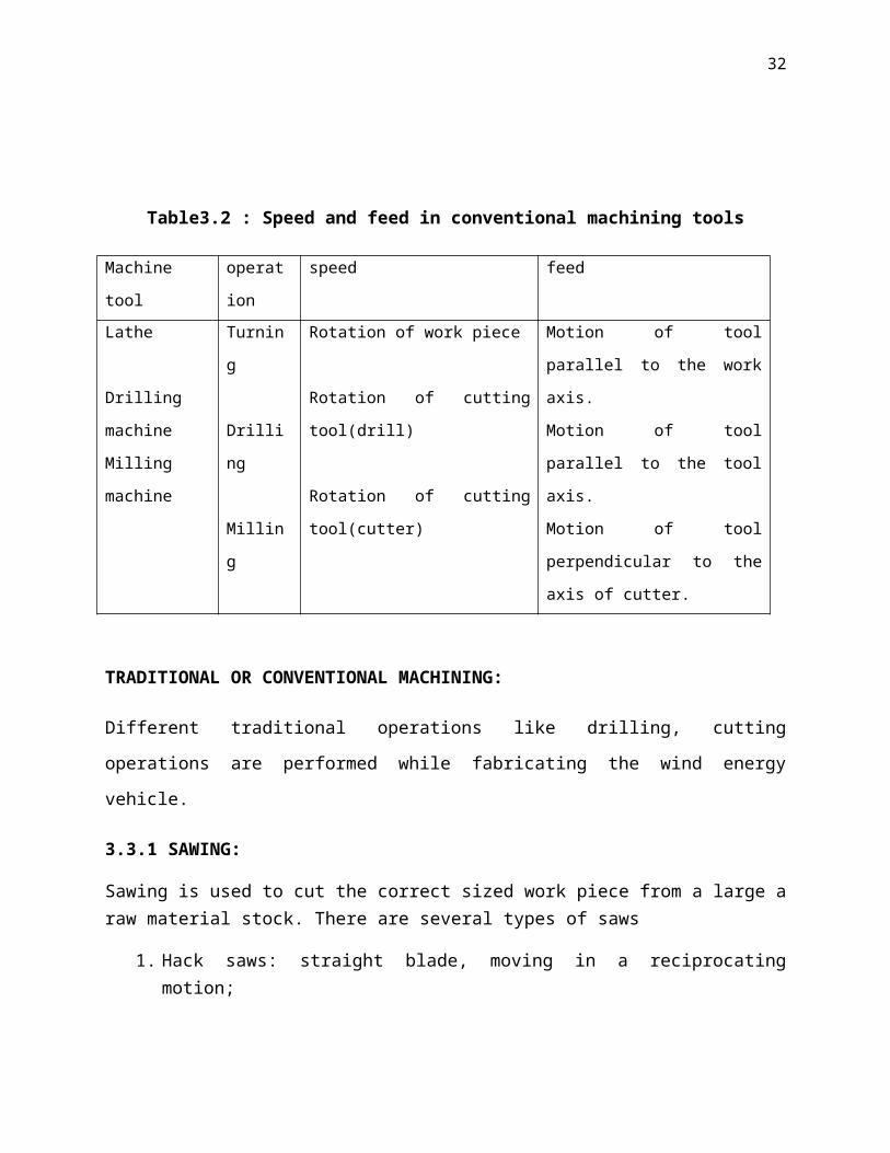
Table3.2 : Speed and feed in conventional machining tools
Machine tool operation speed feed
Lathe
Drilling machine
Milling machine
Turning
Drilling
Milling
Rotation of work piece
Rotation of cutting tool(drill)
Rotation of cutting tool(cutter)
Motion of tool parallel to the
work axis.
Motion of tool parallel to the
tool axis.
Motion of tool perpendicular to
the axis of cutter.
TRADITIONAL OR CONVENTIONAL MACHINING:
Different traditional operations like drilling, cutting operations are performed while fabricating
the wind energy vehicle.
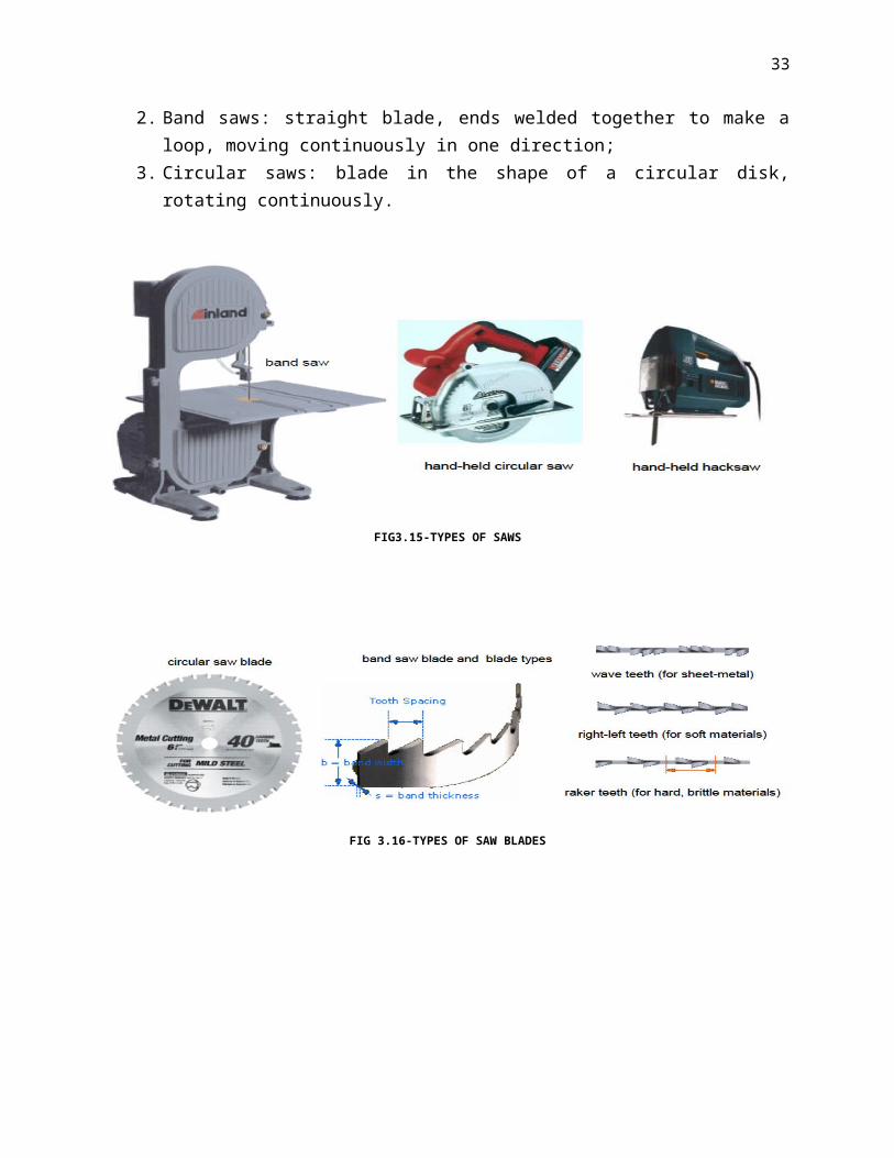
3.3.1 SAWING:
Sawing is used to cut the correct sized work piece from a large a raw material stock. There are several types of saws
1. Hack saws: straight blade, moving in a reciprocating motion;2. Band saws: straight blade, ends welded together to make a loop, moving continuously in
one direction;3. Circular saws: blade in the shape of a circular disk, rotating continuously.
FIG3.15-TYPES OF SAWS

24
FIG 3.16-TYPES OF SAW BLADES
FIG 3.17-TYPICAL SAWING ACTIONS
3.3.2 DRILLING MACHINE OPERATIONS:
DRILLING:
Drilling is the process of making a cylindrical hole by rotation of cutting tool, called drill.
Before drilling, the hole location should be marked out and centre punched. This helps the drill
to start at correct location. The accuracy and surface finish of drilled holes are poor, and can be
improved by jig. Twist drill is most commonly used in workshop.

25
Twist drill: It has two cutting edges and two helical grooves. These helical grooves are called
flutes. These flutes admit coolant and allow the chips to escape during drilling. These are made
of HSS. For drilling, harder materials cemented-carbide drills are used. The standard twist drill
has 2 main parts.
1. Body
2. Shank
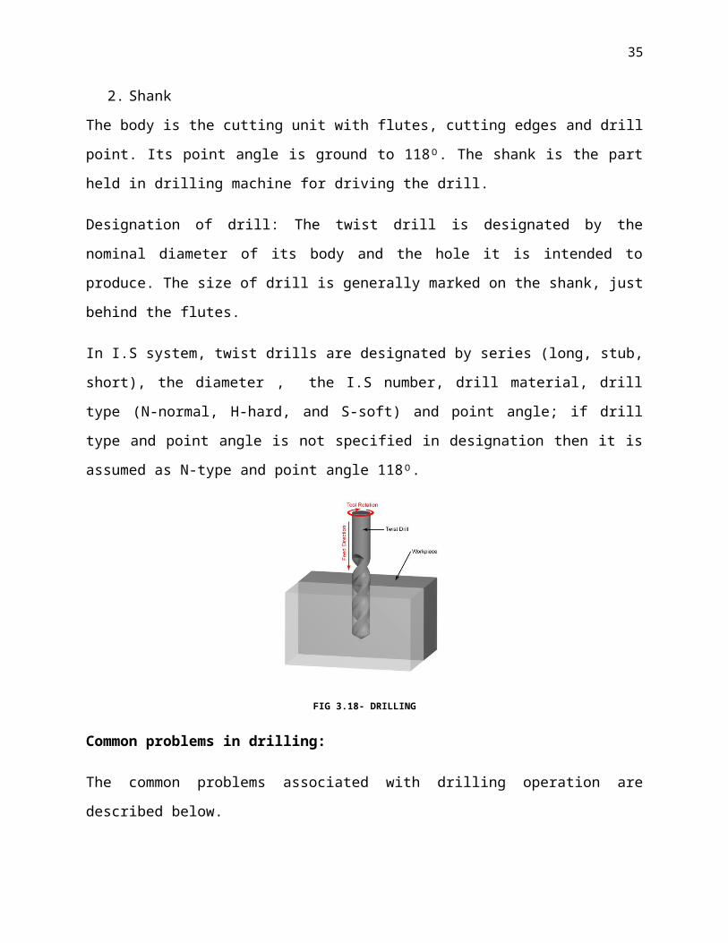
The body is the cutting unit with flutes, cutting edges and drill point. Its point angle is ground to
118ᴼ. The shank is the part held in drilling machine for driving the drill.
Designation of drill: The twist drill is designated by the nominal diameter of its body and the
hole it is intended to produce. The size of drill is generally marked on the shank, just behind the
flutes.
In I.S system, twist drills are designated by series (long, stub, short), the diameter , the I.S
number, drill material, drill type (N-normal, H-hard, and S-soft) and point angle; if drill type and
point angle is not specified in designation then it is assumed as N-type and point angle 118ᴼ.
FIG 3.18- DRILLING
Common problems in drilling:
The common problems associated with drilling operation are described below.
1. Drill drift away from the centre: When starting a hole, a drill is tends to drift away from
the centre due to sliding action of the chisel point. The use of centre drill helps to assure
that drill starts drilling at the desired location.

26
2. Over size of holes: Imperfect drill geometry and machine flexibility are the causes for
oversize of holes. To avoid this regrind point correctly and recondition the machine.
3. Rough holes: Rough holes are caused if the feed rate is high, the cutting edges are not
sharp and cooling is ineffective. This can be avoided by regrinding the point, reducing
the feed rate and using sufficient coolants.
4. Removal of chips and supply of cutting fluids: With deep drilling, the problems of
removal of chips from the cutting edges and supply of cutting fluids to the drill point are
intensified. These problems can be avoided by step-in-step drilling. In this technique the
drill is withdrawn completely from the hole after each step. During each step, the drill is
fed a distance equal to its diameter. This permits the chips to be removed and the drill
hole to be filled with cutting fluids for each step. These problems can be avoided by
using oil hole drill. Cutting fluids, under pressure, enters the drill point and forces the
chips up through the flutes.
5. Drill failure: Twist drill suffer early failure due to incorrect geometry of drill point,
selection of incorrect speeds and feeds, and mishandling of the equipment. This can be
avoided by regrinding the point, reducing the feed rate, recondition the machine and re-
clamps the fixtures
REAMING:
Reaming is the process of making a hole smoothly and accurately to size. To finish the hole to
required size, it should be drilled under size and then reamer is used. Material allowance left in
the hole for hand reaming is usually 0.05mm to 0.1mm, and for machine reaming it ranges from
0.13mm to 0.1mm. In reaming the metal is removed in one cut and a supply of the cutting fluid is
an important feature while reaming. The tool used for reaming process is multi point cutting tool
called reamer.
Reamers with helical flutes ensures better finish of the hole than straight flutes, but their
manufacturing and sharpening are difficult, and are applied to finish holes with grooves or
keyways.

27
Parts of reamer: Reamers are made of high carbon steel or high speed steel. The main parts of
reamer are body and shank. The body of the reamer contains the straight or helical flutes; and
shank may be either straight or tapered.
FIG 3.19-REAMING
Feeds and speeds for reaming will depend on work material, type of reamer and condition of
machine. Feeds for reaming are usually much higher than those for drilling. While the speed are
relatively small as compared to equivalent drilling. With standard reamers of HSS, the feed can
be taken as 2 to 3 times that for a drill of the same diameter and the speed as 23
to 34
of that for
drill of the same diameter.
Reaming always preceded by drilling. The drill size is chosen so as to leave a stock allowances
for reaming. Material allowances left in a hole for hand reaming is usually 0.05 to 0.1mm. The
allowance for machine reaming depends on reamer size.
Table 3.3: Allowances for reaming process
Reamer size range Allowances for reaming
1.5 to 3.0 mm
3.0 to 6.0 mm
6.0 to 12.5 mm
12.5 to 25 mm
25.0 to 35 mm
0.13 to 0.2 mm
0.15 to 0.28 mm
0.25 to 0.38 mm
0.25 to 0.5 mm
0.38 to 0.65 mm

28
TAPPING:
Tap is a multi-fluted tool for producing internal threads in previously drilled hole. Longitudinal
flutes are formed to make series of cutting edges in the form of threads and to provide space for
easy flow of chips when the tap is in operation. Tap has a Shank and a round body with two or
more flutes that may be straight or helical. They are made with high carbon steel or high speed
steel.
FIG 3.20- PARTS OF TAP
The tap is rotated by means a tap wrench. The taper of the tap allows it to enter hole easily and
the thread form will draw the tap forward. It is not necessary too much pressure to force the tap
into the hole. Before tapping, it is essential that the tap is aligned properly with the hole.
The tap is specified by major diameter which is the outside diameter of the tool, over the thread
crest at the first full thread behind the chamfer i.e., Taper lead. The tolerance range, pitch and tap
materials are also generally furnished in the specification. In general the taps are identified with a
number marked on it. A tap with the marking M12*17.5 would indicate a metric thread of 12mm
nominal diameter, and 1.75mm pitch.
FIG 3.21-TAPPING OPERATION
29
Types of taps:
Taps are classified as
1. Machine taps
2. Hand taps
Machine taps must be designed to withstand the torque required to thread a hole and must be
able to remove the chips from the flutes.
Hand taps are available in sets containing the following three taps
1. Taper or first tap (rough tap)
2. Plug or second tap (semi-finish tap)
3. Bottoming tap ( finish tap)
The taper tap is used for easy starting and has provided with taper end for a length of 6 threads.
The purpose of taper is to ensure that the tap enters the hole and maintains the correct alignment.
The plug tap has a tapered end for a length about 3 to 4 threads and is used after the taper tap.
The taper and plug taps may be used for through holes.
The Bottoming tap is used, along with taper and plug taps for threading blind hole to the very
bottom of the hole.
Different sizes of taps are used during tapping process.
Table 3.4: Drill sizes for ISO metric threads
S No Major diameter(mm) Minor diameter(mm) Pitch(mm) Tapping size(mm)
1
2
6
12
4.773
9.85
1
1.75
5
10.2
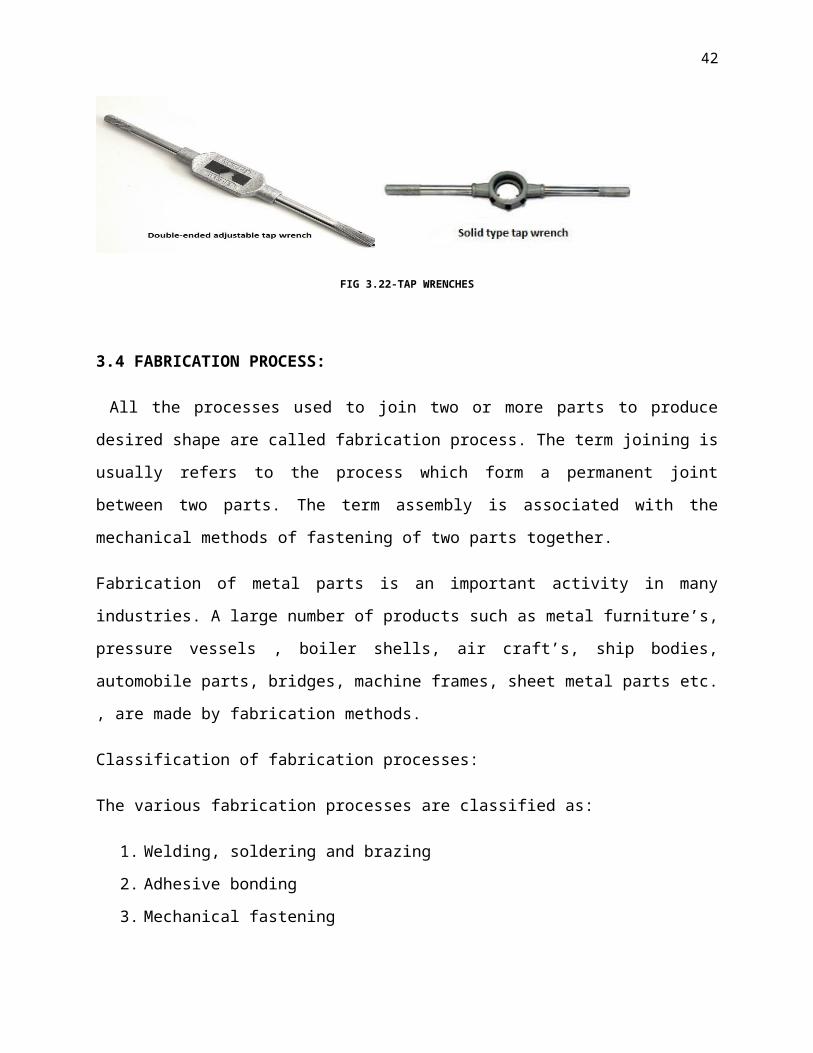
Tap Wrenches: tap wrenches are used to align and drive the hand tap into the hole to be threaded.
The following types of wrenches are commonly used.
1. Solid type tap wrench, and
2. Double-ended adjustable tap wrench

30
Double-ended adjustable tap wrench is most commonly used. It accommodates various sizes of
taps. It is important to select the correct size of the wrench.
FIG 3.22-TAP WRENCHES
3.4 FABRICATION PROCESS:
All the processes used to join two or more parts to produce desired shape are called fabrication
process. The term joining is usually refers to the process which form a permanent joint between
two parts. The term assembly is associated with the mechanical methods of fastening of two
parts together.
Fabrication of metal parts is an important activity in many industries. A large number of products
such as metal furniture’s, pressure vessels , boiler shells, air craft’s, ship bodies, automobile
parts, bridges, machine frames, sheet metal parts etc. , are made by fabrication methods.
Classification of fabrication processes:
The various fabrication processes are classified as:
1. Welding, soldering and brazing
2. Adhesive bonding
3. Mechanical fastening
Welding, soldering, and brazing produce permanent joints. Soldering and brazing uses filler
materials, and involves lower temperature than welding. Soldered and brazed joints can be
separated by heating to temperature greater than the melting point of filler material.

31
Adhesive bonding uses filler materials (adhesive) to hold the parts together permanently. It is
widely used for joining of plastics, metals and other dissimilar metals.
Mechanical fastening involves use of rivets, bolts and nuts. Bolts and nuts are used to make
temporary joints which can be disassembled whenever necessary. Rivets are used to make
permanent joints in metals. Riveted joints can be separated by cutting rivet head without
damaging the parts.
The choice of fabrication process mainly depends on the following factors:
Type of joint
Material being joined
Shape, thickness and size of the parts to be joined
Service requirements
Operation skills required
Cost of the equipment.
3.4.1 ELECTRIC ARC WELDING:
Electric arc welding is performed between cylinder and bottom flange.
In electrical arc welding, the intense heat of electric arc is used to fuse the parts being joined. In
most arc welding processes, the arc is struck between electrode and work piece, and is referred as
direct arc. The arc struck between non-consumable electrodes adjacent to the parts being joined
is called indirect arc. In this case, the heat is transferred to metal by radiation. This method is
rarely used because of low thermal efficiency.
Electric arc welding is preferred over gas welding, because the speed and ease with which welds
may be made. Electric welding equipment is more expensive, but operating cost is lower.
Principle of arc welding:
The principle of arc welding is based upon the formation of an electric arc between consumable
electrode (bare or coated) or non-consumable electrode and the base metal. The heat of the arc is
concentrated at the point of welding, and as a result, it melts the electrode (consumable
32
electrode) and the base metal. When the weld metal solidifies, a sound joint is formed. When the
metal solidifies, the slag gets deposited on its surface as it is lighter than metal, and the weld
metal is allowed to cool gradually and slowly. The slag deposited over the weld is removed by
chipping.
The electric arc is produced when the current flows across the air gap between the end of metal
electrode and the work surface. This arc is strong stable electric discharge occurring in the air
gap between an electrode and the work. The temperature of this arc is about 3600 C which can
melt and fuse the metal very quickly to produce joint. The temperature of the arc at the centre is
around 6500C. Only 60 to 70% of the heat is utilised in arc welding to heat up and melt the
metal. The remaining 40 to 30% is dissipated into surroundings.
FIG 3.23- ELECTRIC ARC WELDING
Metal arc welding is the most common type of arc welding and it is normally a manual
operation. Therefore it is usually referred as Manual Metal Arc Welding (MMAW). It uses
consumable metal electrodes. The arc is produced with low voltage (20-80V) but with very high
current (80-500amps). The electric circuit consistsa.c or d.c power source, and from the power
source welding current is conveyed to work through electrode, electrode holder and welding
leads. The circuit is completed by sinking the arc i.e., making the contact between electrode and
work. The operator maintains arc at required intensity.
33
FIG 3.24- ARC WELDING
The sequences of steps involved in arc welding operation are:
1. Preparation of edges,
2. Holding the work piece in a fixture,
3. Striking the arc, and
4. Welding the joint
Before welding, the edges of the work pieces are suitably prepared, and the joint area is cleaned
with the wire brush. This ensures sound joint. The parent metals are held in a fixture and welding
leads are properly connected to power source.
The arc is struck by scratching the tip of electrode on the parent metal. As the electrode tip
makes contact, the current flows and then as it is drawn away an arc is formed across the gap.
Arc can also be struck by tapping down the electrode to make contact with work piece and is
then raised to maintain a constant gap across which an arc is formed.
During the welding, the electrode is given the following motions.
i. The electrode is fed downwards, and it should be controlled properly to maintain constant
gap (2-4mm)
ii. The electrode is moved slowly along the joint.

34
iii. The electrode tip is given an oscillating movement across the (weaving motion) weld to
maintain proper bead width and secure good penetration of the weld. The width of weave
should not be greater than 3 times the diameter of the electrode.
In multi-pass welding, slag coated on the bead after the first pass should be chipped off and
cleaned by wire brush before the start of the second pass. The procedure is followed for the
subsequent passes. In most cases, after welding, the part must be heat-treated to change the size
of the grain in the weld bead and the surrounding area.
Selection of electrodes:
Type of electrode used depends upon:
i. The type of metal to be welded
ii. The position in which the weld is to be done
iii. The power source
iv. Polarity, in case of D.C
v. Thickness of the base metal
vi. Expected properties of the welded joint.
Bare electrodes are used for welding low carbon steel or wrought iron. They are also mostly used
in submerged arc welding. Coated electrodes are employed for welding high carbon steels, alloy
steels and non-ferrous metals and their alloys. It is best to follow the recommendations of
manufacturers for using electrodes for different work.
Advantages and limitations of arc welding:
Arc welding offer the following advantages:
1. Metal arc welding is faster and lower in cost than gas welding.
2. The process is a quite versatile, and welds can be made in any position.
3. Suitable for wide range of metals (ferrous and non-ferrous) and their alloys.
4. Less sensitive to weld than other processes.
However, the arc welding process has the following limitations:
35
1. The process is not suitable for thin sections.
2. The process is not suitable for mechanisation.
3. Electrode replacement is necessary for long joints.
4. Not suitable for heavy fabrications because less metal is deposited per hour.
5. Failure to remove the slag when run is interrupted leads to slag inclusions in the weld.
Applications:
The Manual Metal Arc Welding (MMAW) has a wider field of applications. It is employed for
fabrication of pressure vessels, ships, structural steel work, and joints in pipe work, construction
and repair of machine parts.
This process can also be used for hard facing and repairs of the broken parts.
3.4.2 SOLDERING:
Soldering is a process in which two or more metal items are joined together by melting and
flowing a filler metal (solder) into the joint, the filler metal having a lower melting point than the
adjoining metal. Soldering differs from welding in that soldering does not involve melting the
work pieces. In brazing, the filler metal melts at a higher temperature, but the work piece metal
does not melt. In the past, nearly all solders contained lead, but environmental concerns have
increasingly dictated use of lead-free alloys for electronics and plumbing purposes.
FIG 3.25-SOLDERING OPERATION

36
SOLDERS:
Soldering filler materials are available in many different alloys for differing applications. In
electronics assembly, the eutectic alloy of 63% tin and 37% lead (or 60/40, which is almost
identical in melting point) has been the alloy of choice. Other alloys are used for plumbing,
mechanical assembly, and other applications. Some examples of soft-solder are tin-lead for
general purposes, tin-zinc for joining aluminium, lead-silver for strength at higher than room
temperature, cadmium-silver for strength at high temperatures, zinc-aluminium for aluminium
and corrosion resistance, and tin-silver and tin-bismuth for electronics.
A eutectic formulation has advantages when applied to soldering: the liquidus and solidus
temperatures are the same, so there is no plastic phase, and it has the lowest possible melting
point. Having the lowest possible melting point minimizes heat stress on electronic components
during soldering. And, having no plastic phase allows for quicker wetting as the solder heats up,
and quicker setup as the solder cools. A non-eutectic formulation must remain still as the
temperature drops through the liquidus and solidus temperatures. Any movement during the
plastic phase may result in cracks, resulting in an unreliable joint.
Common solder formulations based on tin and lead are listed below. The fraction represents
percentage of tin first, then lead, totaling 100%:
63/37: melts at 183 °C (361 °F) (eutectic: the only mixture that melts at a point, instead
of over a range)
60/40: melts between 183–190 °C (361–374 °F)
50/50: melts between 185–215 °C (365–419 °F)
For environmental reasons (and the introduction of regulations such as the European RoHS
(Restriction of Hazardous Substances Directive)), lead-free solders are becoming more widely
used. They are also suggested anywhere young children may come into contact with (since
young children are likely to place things into their mouths), or for outdoor use where rain and
other precipitation may wash the lead into the groundwater. Unfortunately, most lead-free
solders are not eutectic formulations, melting at around 250 °C (482 °F), making it more difficult
to create reliable joints with them.

37
Other common solders include low-temperature formulations (often containing bismuth), which
are often used to join previously-soldered assemblies without un-soldering earlier connections,
and high-temperature formulations (usually containing silver) which are used for high-
temperature operation or for first assembly of items which must not become unsoldered during
subsequent operations. Alloying silver with other metals changes the melting point, adhesion and
wetting characteristics, and tensile strength. Of all the brazing alloys, silver solders have the
greatest strength and the broadest applications. Specialty alloys are available with properties
such as higher strength, the ability to solder aluminum, better electrical conductivity, and higher
corrosion resistance.
FIG 3.26- SOLDER
3.4.3 MECHANICAL FASTENING:
Mechanical fastening is a widely used, cost-effective means of joining, which is particularly
suitable for thin sheet sections. Fastening encompasses a range of processes that utilise a variety
of fasteners including nuts & bolts, screws & rivets, or mechanical interlocks to assemble
materials without heating. The high production rate techniques include:
Clinching - which uses a special punch and die to form a mechanical interlock between
the sheet metals being joined
Self-piercing riveting - in which a semi-tubular rivet is set using a punch and die to flare
the rivet within the lower sheet so that no pre-existing hole is required.

38
FIG 3.27- BOLTS AND NUTS
Mechanical joining falls into two distinct groups: fasteners and integral joints. Examples of
fasteners include: nuts and bolts, screws, pins and rivets; examples of integral joints include:
seams, crimps, snap-fits and shrink-fits.
Some form of mechanical joining needs to be used where products need to be taken apart during
their normal life, e.g. where repair or maintenance is likely.
With the move towards efficient recycling, there is likely to be increased use of mechanical
fastening.
FIG 3.28- BOLTS AND NUTS
Bolts & nuts:
A nut is a type of fastener with a threaded hole. Nuts are almost always used opposite a
mating bolt to fasten a stack of parts together. The two partners are kept together by a
combination of their threads' friction, a slight stretch of the bolt, and compression of the parts. In

39
applications where vibration or rotation may work a nut loose, various locking mechanisms may
be employed: Adhesives, safety pins or lock wire, nylon inserts, or slightly oval-shaped threads.
The most common shape is hexagonal, for similar reasons as the bolt head - 6 sides give a good
granularity of angles for a tool to approach from (good in tight spots), but more (and smaller)
corners would be vulnerable to being rounded off. Other specialized shapes exist for certain
needs, such as wing nuts for finger adjustment and captive nuts for inaccessible areas.
A wide variety of nuts exists, from household hardware versions to specialized industry-specific
designs that are engineered to meet various technical standards.

40
CHAPTER 4
ADVANTAGES:
1. Become more productive: more work can be done by using the product versus walking
2. Become more recognizable: Riders stand an additional eight inches off the ground;
allowing you to be better seen and giving the rider better sight lines, over cars in a
parking lot or boxes in a warehouse.
3. low operating costs: no need for gas and inexpensive battery charging (A complete cycle
charge will take eight to ten hours)
4. reduce fatigue caused by walking
5. a clean, green, eco-friendly machine! (zero emission)
DISADVANTAGES:
1. slow, having a max speed of 12.5 mph
2. does not exactly say how far the Segway will go with riders of different masses
3. unlike bicycles, a drained Segway cannot be pedaled home or a charger

41
CHAPTER 5
RESULTS AND DISCUSSIONS
Project is been successful.It can withhold weight up to75kgs andtravelswith a speed of 12.5mph.
It can be used in construction sites, offices and even lawns to travel from one place to other
withmuch less human effort. It is cost efficient since it doesn’t need any sort of petrol, diesel gas
etc... It is highlyecofriendly as there are no harmful emissions.
42
CHAPTER 6
CONCLUSION
The robot was a success overall. All of the physical requirements for the robot were completed
effectively. The robot was under budget and underweight. The real issue holding the project
back from “total” success was the time constraint. The program was not functioning up to its full
potential, but given more time it could be manipulated to achieve all of the goals set forth and
beyond. The Segway balanced itself, balanced the mass temporarily, and saw the line. All of
this included the robot was a great accomplishment.

43
References:
1. “Manufacturing technology” by kalpak Jain.
2. “Production technology” by R.K. Jain and S.C. Gupta.
3. “Metal cutting and machine tool engineering” by Pakirappa.
4. “Machine tools” by C.Elanchezhian and M.Vijayan.
5. http://en.wikipedia.org/wiki/Segway_PT