60518275 optix rtn 600 remote operation guide a(2)
TRANSCRIPT

Document Number
Product Name OptiX RTN 600
Intended Audience
Engineers of Huawei Product Version V100R001
Compiled by Optical Network Product Technical Service Dept.
Document Version V1.0
OptiX RTN 600 Operation Guide
(Networking in the Lab at HQ)
Prepared by Chen Shaoying Date 2008-02-25
Reviewed by Date
Reviewed by Date
Approved by Date
Huawei Technologies Co., Ltd.
All Rights Reserved

OptiX RTN 600 Remote Operation Guide INTERNAL
2011-08-14 Huawei confidential. No spreading without permission. Page 2 of 55
Revision History
Date Version Description Author
2008-02-25 V1.0 Chen Shaoying

OptiX RTN 600 Remote Operation Guide INTERNAL
2011-08-14 Huawei confidential. No spreading without permission. Page 3 of 55
Table of Contents
Chapter 1 Preparations Before Experiment ................................................................................... 8
1.1 Connecting the Experimental Equipment ............................................................................. 8
1.2 Documentation Required for the Experimental Operation .................................................... 9
1.3 Preparing Tools ................................................................................................................... 10
Chapter 2 Introduction to the Experimental Networking Environment .................................... 11
Chapter 3 Experiment Task 1 (Required) ..................................................................................... 12
3.1 Engineering Requirements ................................................................................................. 12
3.2 Engineering Planning .......................................................................................................... 13
3.2.1 NE Attributes ............................................................................................................ 13
3.2.2 Board Configuration ................................................................................................. 13
3.2.3 IF 1+1 Protection Attributes...................................................................................... 14
3.2.4 Information of IF Interfaces ...................................................................................... 14
3.2.5 Information of ODU Interfaces ................................................................................. 15
3.2.6 Timeslot Allocation ................................................................................................... 15
3.2.7 Clock Information ..................................................................................................... 15
3.2.8 Orderwire Information .............................................................................................. 16
3.3 NE Commissioning ............................................................................................................. 16
3.3.1 Powering On the Equipment .................................................................................... 17
3.3.2 Accessing the Web LCT ........................................................................................... 18
3.3.3 Configuring the Data ................................................................................................ 19
3.3.4 Testing Connections of E1 Cables ........................................................................... 29
3.3.5 Testing the Transmit and Receive Optical Power .................................................... 30
3.3.6 Testing the RF Transmit Power ............................................................................... 31
3.4 HOP Commissioning .......................................................................................................... 31
3.4.1 Testing the ECC ....................................................................................................... 32
3.4.2 Testing the Orderwire Phone ................................................................................... 33
3.4.3 Testing the Services ................................................................................................. 33
3.4.4 Switching Test .......................................................................................................... 34
3.4.5 Testing the 24-Hour BER ......................................................................................... 36
Chapter 4 Experiment Task 2 (Required) ..................................................................................... 38
4.1 Engineering Requirements ................................................................................................. 38
4.2 Engineering Planning .......................................................................................................... 38
4.3 NE Commissioning ............................................................................................................. 39
4.4 HOP Commissioning .......................................................................................................... 39
Chapter 5 Network Maintenance Task 1 – Software Upgrade (Optional) ................................. 42
5.1 Preparations Before Upgrade ............................................................................................. 42

OptiX RTN 600 Remote Operation Guide INTERNAL
2011-08-14 Huawei confidential. No spreading without permission. Page 4 of 55
5.1.1 Obtaining the Upgrade Tools ................................................................................... 42
5.1.2 Obtaining Software to Be Upgraded ........................................................................ 42
5.2 Upgrading Software ............................................................................................................ 43
5.2.1 Procedures for Loading the Simulation Package for Upgrade ................................. 43
5.2.2 Check After the Upgrade .......................................................................................... 51
5.3 Loading Multiple NEs .......................................................................................................... 53

OptiX RTN 600 Remote Operation Guide INTERNAL
2011-08-14 Huawei confidential. No spreading without permission. Page 5 of 55
List of Figures
Figure 2-1 Networking environment (NE1 and NE2) .............................................................. 11
Figure 2-2 Networking environment (NE3 and NE4) .............................................................. 11
Figure 3-1 Engineering networking diagram ........................................................................... 12
Figure 3-2 Board configuration of the IDU .............................................................................. 13
Figure 3-3 Timeslot allocation ................................................................................................. 15
Figure 3-4 Serial connection of the E1 port ............................................................................ 36
Figure 4-1 Engineering networking diagram ........................................................................... 38

OptiX RTN 600 Remote Operation Guide INTERNAL
2011-08-14 Huawei confidential. No spreading without permission. Page 6 of 55
List of Tables
Table 3-1 Service requirements............................................................................................... 12
Table 3-2 NE attributes ............................................................................................................ 13
Table 3-3 IF 1+1 protection attributes...................................................................................... 14
Table 3-4 Information of IF interfaces ...................................................................................... 14
Table 3-5 Information of ODU interfaces ................................................................................. 15
Table 3-6 Clock source priority levels ...................................................................................... 15
Table 3-7 Orderwire information .............................................................................................. 16
Table 3-8 NE commissioning items ......................................................................................... 16
Table 3-9 Common alarm management functions .................................................................. 27
Table 3-10 T HOP commissioning items ................................................................................. 31
Table 4-1 Service requirements............................................................................................... 38
OptiX RTN 600 Remote Operation Guide INTERNAL
2011-08-14 Huawei confidential. No spreading without permission. Page 7 of 55
Key words:
OptiX RTN 600, Web LCT, operation guide, NE commissioning, HOP commissioning,
software upgrade
Abstract:
This guide is written for the networking of the OptiX RTN 600 equipment at HQ. It
describes the networking environment, two required deployment commissioning
tasks, and one optional network maintenance task.
Acronyms and abbreviations:
None.
References:
OptiX RTN 600 Radio Transmission System Configuration Guide
OptiX RTN 600 Radio Transmission System Commissioning Guide

OptiX RTN 600 Remote Operation Guide INTERNAL
2011-08-14 Huawei confidential. No spreading without permission. Page 8 of 55
Chapter 1 Preparations before Experiment
This chapter describes how to properly use the experiment environment. Read
through this chapter before you start to operate the online OptiX RTN 600.
1.1 Connecting the Experimental Equipment
For the remote VPN connection of the experimented equipment, refer to the
Instructions for Using the Remote Training Equipment Room (Shenzhen) of the
Optical Network.
The following table lists the IP address and IDs of the OptiX RTN 600 NEs that are
remotely accessed through the VPN.
10.69.4.99 Two IDs of the OptiX RTN 610: 1 and 2
Two IDs of the OptiX RTN 620: 3 and 4
Normally, the OptiX RTN 600 equipment at HQ is powered off. You need to apply to
the microwave product family at the headquarters for the admission to operate the
OptiX RTN 600 equipment.
Contact person: Chen Shaoying/59800 (Email: [email protected])
Version of the OptiX RTN 600 equipment in the lab at HQ: V100R001C02
NMS version: Web LCT of version V200R005 or higher
For the functional differences between different NMS versions, refer to the relevant
T2000 release notes at the support.huawei.com website, such as the OptiX iManager
T2000 V200R005C01B01C Web LCT Release Notes.

OptiX RTN 600 Remote Operation Guide INTERNAL
2011-08-14 Huawei confidential. No spreading without permission. Page 9 of 55
Caution:
Do not modify key information such as the NE ID or IP address. Otherwise, the remote
operations of the OptiX RTN 600 equipment by other persons is affected.
In certain areas, due to the low network speed, the NMS may run at a low rate, and
the response may be delayed during the experimental operation. In this case, wait
until the operation becomes normal. Do not repeat the operation again and again,
thus increasing the network burden.
1.2 Documentation Required for the Experimental Operation
Caution:
Before you start to operate the OptiX RTN 600 equipment, the following requirements
must be met:
You must have learnt the information of the OptiX RTN 600 equipment and attended
configuration-related courses.
The required documents as stated in this guide must be available.
Relevant product manuals:
OptiX RTN 600 Radio Transmission System Commissioning Guide
OptiX RTN 600 Radio Transmission System Configuration Guide
OptiX RTN 600 Radio Transmission System Hardware Description
OptiX RTN 600 Radio Transmission System Feature Description
OptiX RTN 600 V100R001 Software Upgrade Guide
Software Quality Standard for Microwave
Multimedia:
Link: RTN 600 Training
Specified path: Documentation > Optical Network Product Line > Microwave>
Microwave Products > Function and Feature >Training Document > Level 1
Training slides:
Link: OptiX RTN 600 Slides and Digital Microwave Communication Principles

OptiX RTN 600 Remote Operation Guide INTERNAL
2011-08-14 Huawei confidential. No spreading without permission. Page 10 of 55
Specified path: Documentation > Optical Network Product Line > Microwave>
Microwave Products > Function and Feature >Training Document > Level 1
The following table lists the corresponding course files and links.
Category Course File Multimedia Slide Medium
Installation document
OptiX RTN 600 Hardware Installation and Commissioning
Chinese/English
None Video
Technical document
Digital Microwave Communication Principles
Chinese/English
Chinese/English
Courseware
OptiX RTN 600 Introduction Chinese/English
Chinese/English
Courseware
OptiX RTN 600 Networking and Protection Chinese/English
Chinese/English
Courseware
Operation document
OptiX RTN 600 Equipment Commissioning Chinese/English
Chinese/English
Courseware
OptiX RTN 600 Configuration Chinese/English
Chinese/English
Courseware
OptiX RTN 600 Routine maintenance Chinese/English
Chinese/English
Courseware
1.3 Preparing Tools
Multimeter, BER tester, laptop computer (with the Web LCT installed)

OptiX RTN 600 Remote Operation Guide INTERNAL
2011-08-14 Huawei confidential. No spreading without permission. Page 11 of 55
Chapter 2 Introduction to the Experimental
Networking Environment
Figure 2-1 Networking environment (NE1 and NE2)
Figure 2-2 Networking environment (NE3 and NE4)
As shown in the previous two figures, this system consists of four NEs: NE1, NE2,
NE3, and NE4. NE1 and NE2 adopt the IDU 610, and form a 1+0 radio link. NE3 and
NE4 adopt the IDU 620, and form a radio link that can be configured with 1+1
protection. The used ODUs adopt the 15 GHz-A subband. The transmit frequency of
the ODU at the Tx low station ranges from 14501000 to 14613000. The transmit
frequency of the ODU at the Tx high station ranges from 14921000 to 15033000.
PH1 IF1A
PXC SCC
PH1 IF1A
PXC SCC
15G-A-Lo 15G-A-Hi
NE1: (ID 1) NE2: (ID 2)
IF1A SD1
IF1A EFT4
PXC PH1
PXC SCC
IF1A PH1
IF1A EFT4
PXC SD1
PXC SCC
15G-A-Lo
Coupler
15G-A-Lo
15G-A-Hi
Coupler
15G-A-Hi
NE3: (ID 3) NE4: (ID 4)

OptiX RTN 600 Remote Operation Guide INTERNAL
2011-08-14 Huawei confidential. No spreading without permission. Page 12 of 55
Chapter 3 Experiment Task 1 (Required)
3.1 Engineering Requirements
The engineering requirements are the basis of network planning.
This section describes the networking and service capacity of the OptiX RTN 600
equipment. NE1 to NE4 are microwave transmission NEs. For the slot layout of NE1
to NE4, see Figure 2-1 and Figure 2-2. NE5 is optical network equipment.
Figure 3-1 shows the basic information of the network.
1) The service capacity on the radio link between NE1 and NE2 is 8xE1. This radio
link adopts the 1+0 non-protection configuration. 8xE1 services are required to be
established between NE1 and NE2.
2) The service capacity on the radio link between NE3 and NE4 is STM-1. This radio
link adopts the 1+1 HSB protection. E1 services are required to be established
between NE3 and NE4. The other direction of NE3 is connected to the fiber. One
STM-1 service from NE4 passes through NE3 and then is transparently transmitted to
NE5.
Figure 3-1 Engineering networking diagram
Table 3-1 Service requirements
Source Sink
NE1 NE2 NE3 NE4 NE5
NE1 - 8xE1 - - -
NE2 8xE1 - - - -
NE3 - - - 1xE1 -
NE4 - - 1xE1 - STM-1

OptiX RTN 600 Remote Operation Guide INTERNAL
2011-08-14 Huawei confidential. No spreading without permission. Page 13 of 55
Source Sink
NE1 NE2 NE3 NE4 NE5
NE5 - - - STM-1 -
3.2 Engineering Planning
The parameters of NE1 to NE4 can be planned according to the engineering
requirements and the equipment specifications.
This section considers NE3 as an example and describes how to plan the entire
information required by NE3 according to the engineering requirements and the
equipment specifications.
The methods for planning NE1, NE2, and NE4 are similar to the method for planning
NE3.
3.2.1 NE Attributes
Table 3-2 NE attributes
Parameter Value
Equipment Type IDU 620
NE ID 3
Extended ID 9 (the same as the default value)
NE IP Address 129.9.0.3
NE Name NE3
3.2.2 Board Configuration
Figure 3-2 Board configuration of the IDU
FAN
Slot 20
IF1A Slot 7 SD1 Slot 8
IF1A Slot 5 EFT4 Slot 6
PXC Slot 3 PH1 Slot 4
PXC Slot 1 SCC Slot 2

OptiX RTN 600 Remote Operation Guide INTERNAL
2011-08-14 Huawei confidential. No spreading without permission. Page 14 of 55
Note:
The ODU that connects to the IF board in slot 5/7 occupies slot 15/17.
3.2.3 IF 1+1 Protection Attributes
Table 3-3 IF 1+1 protection attributes
Parameter Value
Protection Group ID 1
Protection Type HSB (default value)
Working Slot Slot 7
Protection Slot Slot 5
Revertive Mode Revertive mode (default value)
Recovery Time 600 s (default value)
Enable Reverse Switching Enable (default value)
Note: IF 1+1 protection need not be configured for NE1 and NE2 in this experimental task.
3.2.4 Information of IF Interfaces
Table 3-4 Information of IF interfaces
Interface Parameter Value
7-IF1A
IF Attributes
Radio Work Mode
Working mode: 7
Service capacity: STM-1
Signal bandwidth: 28 MHz
Modulation mode: 128QAM
Radio Link ID 1
Wayside Enable Status Enabled
Wayside Input Board 1
ATPC Attributes
ATPC Enable Status Enabled
ATPC Upper Threshold (dBm) –40
ATPC Lower Threshold (dBm) –60
ATPC Adjustment (dB) 2

OptiX RTN 600 Remote Operation Guide INTERNAL
2011-08-14 Huawei confidential. No spreading without permission. Page 15 of 55
3.2.5 Information of ODU Interfaces
Table 3-5 Information of ODU interfaces
Interface Parameter Value
17-ODU
Radio Frequency Attributes
Transmit Frequency (MHz) 14550000
T/R Spacing (MHz) 420
Power Attributes Transmit Power (dBm) 5
3.2.6 Timeslot Allocation
Figure 3-3 Timeslot allocation
As shown in Figure 3-3, the service configuration of NE3 is as follows:
NE3 and NE4 have one E1 service that is carried by the wayside service. The
port at which the wayside service exists is the PXC board in slot 1.
One STM-1 service of NE4 is passed through from 7-IF1A to 8-SD1 at NE3.
3.2.7 Clock Information
Table 3-6 Clock source priority levels
Parameter Value
Clock Source 1 7-IF1A
Clock Source 2 5-IF1A
Clock Source 3 Internal Clock Source

OptiX RTN 600 Remote Operation Guide INTERNAL
2011-08-14 Huawei confidential. No spreading without permission. Page 16 of 55
3.2.8 Orderwire Information
Table 3-7 Orderwire information
Parameter Value
Orderwire Telephone No. 103
Call Waiting Time (s) 5
Selected Orderwire Port 7-IF1A-1, 5-IF1A-1, and 8-SD1-1
Orderwire Occupied Bytes E1
Experiment requirement:
Refer to the procedures for planning NE3 to plan the entire information of NE1, NE2,
and NE4 based on the engineering requirements.
3.3 NE Commissioning
During NE commissioning, a single NE is commissioned when the radio link is not
established.
Table 3-8 NE commissioning items
Commissioning Item Required/Opt
ional Reference Remarks
Powering on the equipment
Required Section 3.3.1 Skip this step in the case of remote commissioning.
Accessing the Web LCT
Required Section 3.3.2
In the case of remote commissioning, access the Web LCT according to the Instructions for Using the Remote Training Equipment Room (Shenzhen) of the Optical Network.
Configuring the data Required Section 3.3.3 -
Testing connections of E1 cables
Optional Section 3.3.4 Applies to stations with the E1 services accessed.
Testing the receive and transmit power of the optical interface
Optional Section 3.3.5 Applies to stations with the SDH optical interface services accessed.
Testing the transmit signal level
Required Section 3.3.6 -
This section considers NE3 as an example to describe the procedures of NE
commissioning.

OptiX RTN 600 Remote Operation Guide INTERNAL
2011-08-14 Huawei confidential. No spreading without permission. Page 17 of 55
The commissioning of NE3 includes three parts:
Powering on the equipment
Accessing the Web LCT
Configuring NE3 with services by using the Web LCT and checking the
equipment
After reading through this section, you can learn the entire procedures of NE
commissioning, and can complete commissioning of NE1, NE2, and NE4 accordingly.
3.3.1 Powering On the Equipment
It is recommended that you set the fuse capacity of the power of the IDU 610 to 5 A,
and set the fuse capacity of the power of the IDU 620 to 12 A. The recommended
values meet the requirements of the full configuration. If the fuse needs to be selected
according to the actual configurations, calculate the fuse capacity according to the
following formulas:
48 V power system: fuse capacity = (total power consumption x 1.5)/42
60 V power system: fuse capacity = (total power consumption x 1.5)/52.5
The maximum power consumption of each component of the OptiX RTN 600 is as
follows:
IDU 610: 37 W
IDU 620: 93.8 W
ODU of SP/LP series: 40 W
ODU of HP series: 58 W
Caution:
If the PXC boards are configured with board-level 1+1 protection, the two PXC
boards must use input power with the same standard voltage.
The "SYS-PWR" switch on the PXC board and the "ODU-PWR" switch on the IF
board both have the locking device. Hence, you need to pull the switch lever
outward slightly before dipping it. When the switch is at the "O" position, it
indicates that the locking device is off. When the switch is at the "I" position, it
indicates that the locking device is on.
Step Operation
1 Set the "SYS-PWR" switch on the PXC board to "O".
2 Set the "ODU-PWR" switch on the IF board to "O".

OptiX RTN 600 Remote Operation Guide INTERNAL
2011-08-14 Huawei confidential. No spreading without permission. Page 18 of 55
Step Operation
3 Turn on the power switch of the power supply device of the IDU.
4
Use the multimeter to test the voltage and polarization of the input power at the access point (such as the output terminal of the power box on the cabinet).
If the standard voltage of the input power is –48 V, the tested value of the voltage should range from –38.4 V to –57.6 V.
If the standard voltage of the input power is –60 V, the tested value of the voltage should range from –48 V to –72 V.
5 Set the "SYS-PWR" switch on the PXC board to "I".
6
Check the indicators of each board of the IDU.
Board indicators should comply with the following statuses and sequences:
The "PWR" indicator on the PXC board that has accessed the power of the cabinet must be on (green).
The "PROG" indicator on the SCC board must undergo the entire process: goes on (green), goes off, flashes green, and then goes off.
The "STAT" indicator on the SCC board should on green.
7 Se the "ODU-PWR" switch on the IF board to "I".
Caution:
When the test voltage is beyond the range, first rectify the fault in the power supply
device. The abnormal voltage may cause damage to the equipment, or even personal
injury.
Note:
For the meanings of board indicators, refer to the OptiX RTN 600 Radio Transmission
System Hardware Description.
Due to the impacts of the data configuration, the "STAT" indicator on certain boards is
not lit when the equipment is powered on.
3.3.2 Accessing the Web LCT
1 Start up the laptop computer, and log in to the operating system.
2 Set the IP address of this computer. The IP address should comply with the
following requirements:
IP address: The IP address is within the 129.9.0.0 network segment, and is
different from the IP address of the NE.

OptiX RTN 600 Remote Operation Guide INTERNAL
2011-08-14 Huawei confidential. No spreading without permission. Page 19 of 55
Subnet mask: 255.255.0.0
Gateway (default): null
3 Connect the network interface of the laptop computer to the "ETH" interface of
the SCC board through the network cable and the extension network cable. The
ETH interface supports the MDI/MDI-X autosensing. Hence, you can use the
straight through cable or crossover cable to connect it. In this case, the green
indicators of the "ETH" interface and network interface of the laptop computer
should be on. In addition, when you set the prompt for the local area connection
in the operating system of the laptop computer, the prompt that the network has
been connected is displayed.
4 The IE displays the Login Interface of the Web LCT.
5 Enter the user name and password, and click Login. The default user name is
admin, and the default password is T2000. If the user name and password are
correct, the NE List page is displayed.
3.3.3 Configuring the Data
I. Creating and Logging In to NEs
You can create an NE by searching this NE or manually adding this NE. During NE
commissioning at a station, an NE is created by searching this NE, because the NE ID
is normally not known in the case of initial NE configuration.
For the procedures for creating an NE by searching this NE, refer to the OptiX RTN
600 Radio Transmission System Configuration Guide.
The equipment in the equipment room supports remote commissioning. The NE ID is
preset, and cannot be modified. Thus, NEs can be created by researching the NEs or
manually adding the NEs in the case of operation in the equipment room. NEs can be
created only by manually adding the NEs in the case of remote commissioning.
1 In NE List, click Add NE. The system displays the Add NE dialog box.
2 In the dialog box, set the NE ID to “3”, and the password to “password”.
3 Click OK. At this time, a new NE is added into the NE List.
4 Double-click the logged NE or click NE Explorer. Then the NE Explorer is
displayed.

OptiX RTN 600 Remote Operation Guide INTERNAL
2011-08-14 Huawei confidential. No spreading without permission. Page 20 of 55
Note:
When the logical boards that are configured with an NE are inconsistent with the
physical boards, the slot layout diagram will be different from the slot layout as shown
in this figure. To learn the specific meanings of the slot layout, click Legend.
II. Initializing NEs
The equipment in the equipment room at HQ has been commissioned for several
times during training, and thus may contain information of previous commissioning. In
this case, it is recommended that you initialize the equipment and clear all original
configurations on the equipment before NE configuration.
1 Select the NE in the Object Tree in the NE Explorer. Choose Configuration >
Quick Configuration from the Function Tree.
2 Click Next. Then the Quick Configuration dialog box is displayed.

OptiX RTN 600 Remote Operation Guide INTERNAL
2011-08-14 Huawei confidential. No spreading without permission. Page 21 of 55
3 Click Next. The Quick Configuration dialog box is displayed.
4 Click Exit. Check the NE explorer and find that only 2-SCC/21-EOW exists in the
Object Tree.
III. Modifying the NE ID/IP Address
The NE ID needs to be modified based on the engineering plan, during the site
commissioning, to ensure that the NE ID is unique. The modification does not affect
services but affect the communication between the Web LCT and the NE. After the
modification of the NE ID, create the NE, log in to it again and then you can establish
the communication between the NE and the Web LCT.
1 Select the NE from the Object Tree in the NE Explorer. Choose Configuration >
NE Attribute from the Function Tree.
2 Click Modify NE ID. The system displays the Modify NE ID dialog box.
3 Set the NE ID by referring to Table 3-2.
4 Click OK.

OptiX RTN 600 Remote Operation Guide INTERNAL
2011-08-14 Huawei confidential. No spreading without permission. Page 22 of 55
After the NE ID is modified, you can modify the NE IP address based on the
engineering plan.
The NE IP address is normally set to be related to the NE ID, that is, the first byte of
the IP address is set to "129“, the second byte of the IP address is set to be the same
as the extended NE ID, and the last two bytes are set to be the same as the NE ID.
For example, when the NE ID is "49136" and the extended NE ID is "9", the NE IP
address should be "129.9.191.240", in which 191 x 256 + 240 = 49136.
Caution:
In the case of remote access, the NE ID/IP address cannot be modified.
If the NE ID is modified during site operation in the equipment room, change the NE ID
to the original value after the commissioning. Otherwise, later remote operations may
be affected.
IV. Adding Logical Boards
If a physical board does not match the board as allocated in the slot layout diagram
(that is, logical board), re-configure the logical board in the slot layout diagram. The
NE software manages the physical board as one or multiple logical boards. In the
case of the OptiX RTN 600:
The SCC physical board is managed as two logical boards: SCC and EOW. The
slot for the logical SCC board is slot 1, and the slot for the logical EOW board is
slot 21.
Any other physical board of the IDU is managed as the logical board with the
same name. The slot number of the logical board is the same as the slot number
of the physical board.
The ODU is managed as a logical board ODU. The slot number for the logical
board is the slot number of the IF board that the ODU is connected to plus 10.
1 Observe the Slot Layout on the NE Explorer. Specify the boards to be added or
deleted depending on the legend and the physical boards.
2 Right-click the slot of which the board is to be deleted, and select Delete from the
drop-down menu. Before deleting the board, delete the services, clock priority
level, orderwire (broadcast data), and protection configuration on the board.
3 Right-click the slot in which a board is to be inserted, and select Add xxx. "xxx"
indicates the name of the board to be added. You can add the IF boards and
service boards only if the PXC board is added.

OptiX RTN 600 Remote Operation Guide INTERNAL
2011-08-14 Huawei confidential. No spreading without permission. Page 23 of 55
Note:
The STAT indicator will be lit only when the physical boards on the IDU match the
logical boards.
V. Configuring IF 1+1 Protection
If a radio link is configured with the 1+1 HSB/FD/SD protection, the relative
information of the IF 1+1 protection needs to be configured.
1 Select the board from the Object Tree in the NE Explorer. Choose
Configuration > IF 1+1 Protection from the Function Tree.
2 Click Create. The system displays the Create IF 1+1 Protection dialog box.
3 Configure each parameter of the IF 1+1 protection based on the planned IF 1+1
protection attributes.
4 Click OK.
VI. Configuring the Information of IF Interfaces
When no protection is configured, each IF board needs to be configured with IF
interface information.
When the 1+1 protection is configured, only working IF boards need to be configured
with IF interface information.
1 Select 7-IF1A from the Object Tree in the NE Explorer. Choose Configuration >
IF Interface from the Function Tree.
2 Select the IF Attributes tab.
3 Configure each parameter of the IF attributes by referring to Table 3-4.

OptiX RTN 600 Remote Operation Guide INTERNAL
2011-08-14 Huawei confidential. No spreading without permission. Page 24 of 55
4 Click Apply.
5 Select the ATPC Attributes tab.
6 Configure each parameter of the ATPC attributes.
Note:
During the commissioning, set ATPC Enable Status to Disabled to prevent any
change in the transmit power. Set the ATPC attributes after the commissioning is
complete.
7 Click Apply.
VII. Configuring the Information of ODU Interfaces
In the non-protection and 1+1 FD mode, the working and protection ODUs must be
configured with ODU interface information.
In the 1+1 HSB and the 1+1 SD mode, only the RF attributes and power attributes
need to be configured for the working ODU, and the transmission status needs to be
configured for the working and protection ODUs.
1 Select 17-ODU from the Object Tree in the NE Explorer. Choose
Configuration > ODU Interface from the Function Tree.
2 Select the Radio Frequency Attributes tab.
3 Refer to Table 3-5 to configure the transmit frequency and T/R spacing.
Note:
Only 8 GHz and 18 GHz frequency bands support setting two values for the T/R
spacing parameter. In this band, the T/R spacing must be set in an accurate manner.
In other bands, the T/R spacing can be set to 0, as the ODU automatically adopts the
default value.
4 Click Apply.
5 Click the Power Attributes tab.
6 Configure the transmit power of the ODU.
7 Click Apply.
8 Click the Advanced Attributes tab.
9 Set Configure Transmission Status to unmute.
10 Click Apply.
11 Select 15-ODU from the Object Tree in the NE Explorer. Choose
Configuration > ODU Interface from the Function Tree.

OptiX RTN 600 Remote Operation Guide INTERNAL
2011-08-14 Huawei confidential. No spreading without permission. Page 25 of 55
12 Click the Advanced Attributes tab.
13 Set Configure Transmission Status to unmute.
14 Click Apply.
VIII. Configuring Cross-Connections of Services
1 Select NEs from the Object Tree in the NE Explore. Choose Configuration >
Cross-Connection Configuration from the Function Tree.
2 Click Create. The Create SDH Services dialog box is displayed.
3 Refer to the timeslot allocation as shown in Figure 3-3, and configure NE3 with
pass-through services.
4 Click OK.
Note:
The add/drop E1 services on NE3 are transmitted through the wayside service, and
thus need not be configured during the cross-connection configuration.
IX. Configuring the Clock Source
1 Select the NE from the Object Tree in the NE Explorer. Choose Configuration >
Clock > Clock Source Priority from the Function Tree.
2 Click Create. The Add Clock Source dialog box is displayed.
3 Refer to Table 3-6 to select 7-IF1A-1(SDH-1) as the first clock source.

OptiX RTN 600 Remote Operation Guide INTERNAL
2011-08-14 Huawei confidential. No spreading without permission. Page 26 of 55
4 Click OK.
5 Repeat steps 2–4 to select 5-IF1A-1(SDH-1) as the second clock source.
6 Select a clock source, and click or to adjust its priority level.
7 Click Apply.
X. Configuring the Orderwire
When the orderwire is enabled, it can provide a dedicated communication channel for
the network maintenance engineers.
1 Select the NE from the Object Tree in the NE Explorer. Choose Configuration >
Orderwire from the Function Tree.
2 Click the General tab.
Refer to Table 3-7 to configure the orderwire information.

OptiX RTN 600 Remote Operation Guide INTERNAL
2011-08-14 Huawei confidential. No spreading without permission. Page 27 of 55
3 Click Apply.
4 Click the Advanced tab.
5 Configure Orderwire Occupied Bytes.
XI. Adjusting the Alarm Management Function
To improve the efficiency of alarm monitoring, you can adjust the alarm management
function of a board or port depending on whether the service is available. Table 3-9
lists the common alarm management functions. For details, refer to the Web LCT
online Help.
Table 3-9 Common alarm management functions
Alarm Management
Function Major Application Example
Reversing alarms Used to reverse the alarms of certain ports at which the service is unavailable.
When no service is available at a line port, you can reverse the R_LOS alarm at the port.

OptiX RTN 600 Remote Operation Guide INTERNAL
2011-08-14 Huawei confidential. No spreading without permission. Page 28 of 55
Alarm Management
Function Major Application Example
Suppressing alarms
Used to suppress minor alarms.
When two PXC boards are configured but only one power supply is accessed, you can suppress the VOLT_LOS alarm of the PXC board that is not provided with power.
Setting the bit error alarm threshold
Used to adjust the alarm threshold, depending on the sensitivity of the service to bit errors.
When the data services are carried, you can set the bit error threshold-crossing value to 10-6 and the bit error degrade threshold to 10-8.
XII. Adjusting NE Time
By setting the NE time to be synchronous with the NM time, you can record the exact
time when alarms and performance events occur.
Ensure that the time zone and time on the Web LCT server computer are correctly
set.Select the NE from the Object Tree in the NE Explorer. Choose Configuration >
NE Time Localization Management from the Function Tree.
2 Correctly set the time zone and daylight saving time (SDT) of the NE according to
the location of the NE.
3 Click Apply.
4 Select the NE from the Object Tree in the NE Explorer. Choose Configuration >
NE Time Synchronization from the Function Tree.
5 Set Synchronous Mode to NM.
6 Click Apply.
XIII. Starting Performance Monitoring of the Specific NE
After performance monitoring is enabled, a detailed record of the NE operations is
kept. This helps maintenance engineers to monitor and analyze the operation status
of the NE.
1 Select the NE from the Object Tree in the NE Explorer. Choose Performance >
NE Performance Monitor Time from the Function Tree.
2 Set the performance monitoring parameters according to the requirements.
During the commissioning and troubleshooting process, enable the 15-minute
and the 24-hour performance monitoring at the same time. In the case of normal
operations, enable only the 24-hour performance monitoring.
3 Click Apply.

OptiX RTN 600 Remote Operation Guide INTERNAL
2011-08-14 Huawei confidential. No spreading without permission. Page 29 of 55
3.3.4 Testing Connections of E1 Cables
By testing connections of E1 cables, you can check whether the connections of E1
cables between the equipment and DDF are correct and whether the E1 cables are
normal. E1 cables need not be connected on NE3.
The following procedures for connecting E1 cables apply to NE1 and NE2.
Method 1 (applicable when the BER tester is available during the site commissioning):
Step Operation
1
At the DDF, connect the first E1 port of the OptiX RTN 600 with the BER tester. The BER tester reads the AIS alarm.
There is no DDF in the equipment room at HQ. Instead, the DB44 self-loop cable is used.
2
Set the corresponding E1 port to outloop through the Web LCT.
1) Select the PDH interface board from the Object Tree. 2) Choose Configuration > PDH Interface from the Function Tree. 3) Set Tributary Loopback of the E1 port to Outloop.
3 Observe the BER tester. The AIS alarm should be cleared.
4
Release the outloop of the E1 port through the Web LCT.
1) Select the PDH interface board from the Object Tree. 2) Choose Configuration > PDH Interface from the Function Tree. 3) Set Tributary Loopback of the E1 port to Non-Loopback.
5 Observe the BER tester. The BER tester should report the AIS alarm.
6 Repeat steps 1–5 to test other E1 ports.
Method 2 (applicable in the case of no BER tester during site commissioning or in the
case of remote commissioning):
Use the pseudo-random binary sequence (PBRS) of the OptiX RTN 600 to test the
connections of E1 cables.
OptiX RTN 600 Remote Operation Guide INTERNAL
2011-08-14 Huawei confidential. No spreading without permission. Page 30 of 55
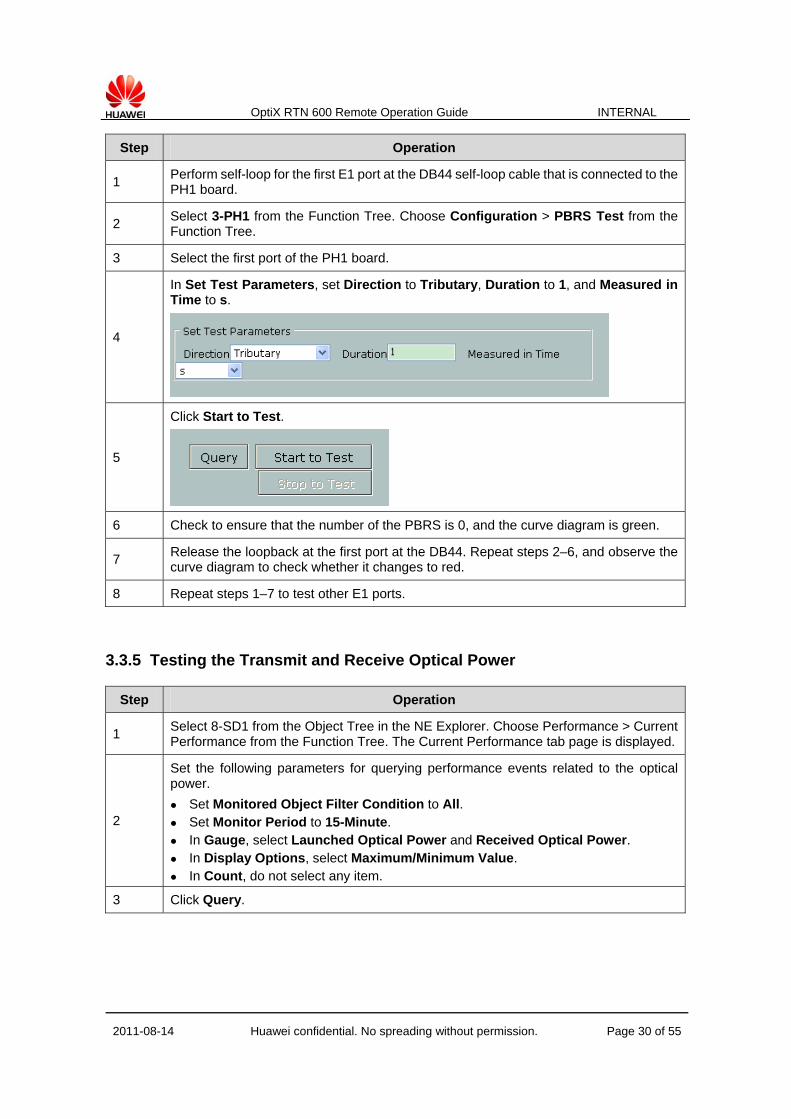
Step Operation
1 Perform self-loop for the first E1 port at the DB44 self-loop cable that is connected to the PH1 board.
2 Select 3-PH1 from the Function Tree. Choose Configuration > PBRS Test from the Function Tree.
3 Select the first port of the PH1 board.
4
In Set Test Parameters, set Direction to Tributary, Duration to 1, and Measured in Time to s.
5
Click Start to Test.
6 Check to ensure that the number of the PBRS is 0, and the curve diagram is green.
7 Release the loopback at the first port at the DB44. Repeat steps 2–6, and observe the curve diagram to check whether it changes to red.
8 Repeat steps 1–7 to test other E1 ports.
3.3.5 Testing the Transmit and Receive Optical Power
Step Operation
1 Select 8-SD1 from the Object Tree in the NE Explorer. Choose Performance > Current Performance from the Function Tree. The Current Performance tab page is displayed.
2
Set the following parameters for querying performance events related to the optical power.
Set Monitored Object Filter Condition to All. Set Monitor Period to 15-Minute. In Gauge, select Launched Optical Power and Received Optical Power. In Display Options, select Maximum/Minimum Value. In Count, do not select any item.
3 Click Query.
OptiX RTN 600 Remote Operation Guide INTERNAL
2011-08-14 Huawei confidential. No spreading without permission. Page 31 of 55
Step Operation
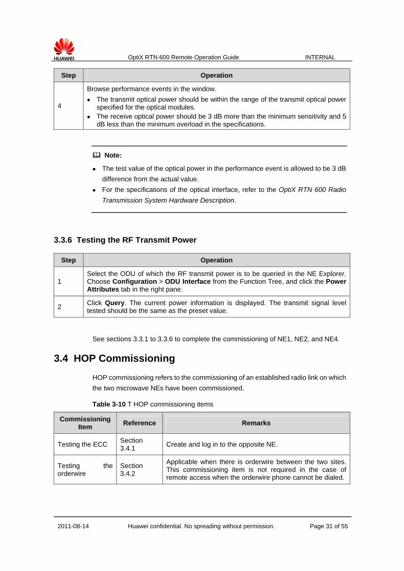
4
Browse performance events in the window.
The transmit optical power should be within the range of the transmit optical power specified for the optical modules.
The receive optical power should be 3 dB more than the minimum sensitivity and 5 dB less than the minimum overload in the specifications.
Note:
The test value of the optical power in the performance event is allowed to be 3 dB
difference from the actual value.
For the specifications of the optical interface, refer to the OptiX RTN 600 Radio
Transmission System Hardware Description.
3.3.6 Testing the RF Transmit Power
Step Operation
1 Select the ODU of which the RF transmit power is to be queried in the NE Explorer. Choose Configuration > ODU Interface from the Function Tree, and click the Power Attributes tab in the right pane.
2 Click Query. The current power information is displayed. The transmit signal level tested should be the same as the preset value.
See sections 3.3.1 to 3.3.6 to complete the commissioning of NE1, NE2, and NE4.
3.4 HOP Commissioning
HOP commissioning refers to the commissioning of an established radio link on which
the two microwave NEs have been commissioned.
Table 3-10 T HOP commissioning items
Commissioning Item
Reference Remarks
Testing the ECC Section 3.4.1
Create and log in to the opposite NE.
Testing the orderwire
Section 3.4.2
Applicable when there is orderwire between the two sites. This commissioning item is not required in the case of remote access when the orderwire phone cannot be dialed.

OptiX RTN 600 Remote Operation Guide INTERNAL
2011-08-14 Huawei confidential. No spreading without permission. Page 32 of 55
Commissioning Item
Reference Remarks
Testing the services
Section 3.4.3
Test the E1 service, Ethernet service, and WS service.
According to the equipment configuration, tests need to be performed for the E1 service between NE1 and NE2, and for the WS service between NE3 and NE4.
Switching test Section 3.4.4
Test IF 1+1 switching, SNCP switching, linear MSP switching, and active/standby switching of the PXC. According to the equipment configuration, the switching test is not required for the link between NE1 and NE2, but tests need to be performed for the IF 1+1 switching and active/standby switching of the PXC on NE3 and NE4.
Testing the 24-hour BER
Section 3.4.5
Skip this step in the case of remote commissioning.
For detailed HOP commissioning items and procedures, refer to the OptiX RTN 600
Radio Transmission System Commissioning Guide.
This section considers the link between NE3 and NE4 as an example to describe the
procedures of HOP commissioning.
The procedures for commissioning the HOP between NE1 and NE2 are the same.
3.4.1 Testing the ECC
Step Operation
1 Access NE3 to the Web LCT.
2
In the NE List page, click Add NE.
Note: If the same laptop computer is used during the NE commissioning of NE4, and the information of NE4 is reserved in the NE List page, the gateway IP address of NE4 is the IP address of NE4, which is 129.9.0.3. To log in to NE4 through NE3, you need ensure that the gateway IP address of NE4 is the IP address of NE3. In this case, you need to delete NE4 from the NE list.
3
Set the following attributes of NE4 in the Add NE page:
NE ID: 4 Extended ID: 9 Gateway Type: IP gateway Gateway IP Address: 129.9.0.3 User Name: root Password: password
4 Click OK. In this case, a row of data for the newly added NE is added in the NE List page.
5 Observe Login Status of the newly added NE. The Login Status should be Logged In.

OptiX RTN 600 Remote Operation Guide INTERNAL
2011-08-14 Huawei confidential. No spreading without permission. Page 33 of 55
3.4.2 Testing the Orderwire Phone
Step Operation
1
Check the status of the orderwire phones on both equipment sides.
The status should meet the following requirements:
The ringing switch is set to "ON". The dialing mode switch must be set to "T", that is, the dual-tone dialing mode must
be selected.
2
Dial the orderwire phone of the opposite equipment as follows:
Pick up the orderwire phone, and press the "TALK" key on the front panel of the phone. At this time, the red indicator on the upper right of the front panel is on, and is accompanied by the dialing prompt tone.
Dial the orderwire phone number of the opposite equipment. Normally, after the opposite end answers, the talking quality is good and the voice is clear.
3
Answer the orderwire phone as follows:
The maintenance personnel on the opposite equipment side dials the orderwire phone of the local equipment. Normally, the orderwire phone rings and at the same time the red indicator at the back of the front panel flashes.
Pick up the phone, and press the "TALK" key for conversation. At this time, the red indicator on the upper right of the front panel is on. Normally, the talking quality is good and the voice is clear.
3.4.3 Testing the Services
I. Testing the E1 Service
This section describes how to test the E1 service during the HOP commissioning
between NE1 and NE2.
Method 1 (applicable when the BER meter is available during the site
commissioning):
Step Operation
1 Connect the first E1 port to the BER tester on the local equipment side.
2 On the opposite equipment side, perform the hardware inloop for the first E1 port. If the hardware inloop fails, perform the software inloop for the E1 port by using the Web LCT.
3 Test the BER for 5 to 10 minutes by using the BER tester. There should be no bit error.
4 Release the loopback.
5 Repeat steps 1–4 to test other E1 ports.
Method 2 (applicable in the case of no BER tester during the site commissioning or in
the case of remote commissioning):

OptiX RTN 600 Remote Operation Guide INTERNAL
2011-08-14 Huawei confidential. No spreading without permission. Page 34 of 55
Step Operation
1
Perform software inloop at the E1 ports for the tributary boards on NE2 by using the Web LCT.
Select the PH1 board from the Object Tree. Choose Configuration > PDH Interface from the Function Tree. Set the tributary loopback of the first path of the PH1 board to Inloop.
2
Perform the PRBS test for the E1 ports of NE1 by using the Web LCT.
Select PH1 from the Function Tree. Choose Configuration > PBRS Test from the Function Tree.
Select the first port of the PH1 board. In Set Test Parameter, set Direction to Tributary, Duration to 1, and Measured in
Time to s. Click Start to Test.
The total number of the PBRS should be 0, and the curve diagram should be green.
3 Release the loopback at the first port.
4 Repeat steps 1–3 to test other E1 ports.
II. Testing the WS Service
This section describes the test of the wayside (WS) service during the HOP
commissioning between NE3 and NE4.
Step Operation
1 At NE3, connect the WS port on the PXC board to the BER tester.
2 At NE4, perform hardware inloop at the WS port on the PXC board.
3 Test the BER for 5 to 10 minutes by using the BER tester. There should be no bit error.
4 Release the loopback at the WS port of NE4.
The wayside service cannot be set with a software loopback; therefore, the WS
service test can be performed only in the case of site commissioning. In the case of
remote commissioning, the WS service test is not required.
3.4.4 Switching Test
I. Testing the IF 1+1 Switching
1 View the working statuses of the boards by using the Web LCT.
(1). Select the NE from the Object Tree in the NE Explorer. Choose Configuration >
IF 1+1 Protection from the Function Tree.
(2). Click Query. The Active Board of Device in the Protection Group interface
should be 7-IF1A.

OptiX RTN 600 Remote Operation Guide INTERNAL
2011-08-14 Huawei confidential. No spreading without permission. Page 35 of 55
Note:
If an abnormal status occurs, you must rectify the fault and proceed to test the IF 1+1
protection.
2 Turn off the ODU power switch on the main IF board.
In the case of remote commissioning, select 17-ODU from the Object Tree and
choose Configuration > ODU Interface from the Function Tree in the NE
Explorer. In Advanced Attributes, set the transmission status of the 17-ODU to
mute.
3 Repeat Step 1 to view the working status of the board. At this time, the Active
Board of Device should be 5-IF1A.
4 After the switching is complete, turn on the ODU power switch on the main IF
board.
In the case of remote commissioning, select 17-ODU from the Object Tree and
choose Configuration > ODU Interface from the Function Tree in the NE
Explorer. In Advanced Attributes, set the transmission status of the 17-ODU to
unmute.
5 When Revertive Mode of the IF 1+1 protection is set to Revertive (the WTR
time is 600s in this example), you can view that the "ACT" indicator on the front
panel of the 7-IF1A board is on 10 minutes after the ODU power switch on the
main IF board is turned on.
In the case of remote commissioning, you can view that the 5-IF1A board is in the
standby state in the slot layout diagram in the NE Explorer.
6 Repeat Step 1 to view the working status of the board. At this time, the Active
Board of Device should be 7-IF1A.
7 Refer to steps 1–10 to test the IF 1+1 protection of the opposite equipment.
II. Testing the Active/Standby Switching of the PXC Board
Step Operation
1 Select the NE from the Object Tree and choose Configuration > Board 1+1 Protection from the Function Tree in the NE Explorer.
2
View the current information of the board 1+1 protection. The working board is 1-PXC, and the protection board is 3-PXC.

OptiX RTN 600 Remote Operation Guide INTERNAL
2011-08-14 Huawei confidential. No spreading without permission. Page 36 of 55
Step Operation
3
Click Working/Protection Switching.
4
A dialog box is displayed. Click OK.
5
Query the current status of the board 1+1 protection. As shown in the following figure, the working board is 3-PXC, and the protection board is 1-PXC.
Note: The board 1+1 protection is non-revertive. Even if the 1-PXC board is normal, the equipment does not automatically switch the services back to the 1-PXC until the 3-PXC becomes faulty.
6 Repeat steps 2–4 to switch the services back to the original working board 1-PXC.
3.4.5 Testing the 24-Hour BER
1 On the opposite equipment side, extract several typical E1 services, and perform
hardware inloop for these E1 ports. If the hardware inloop fails, perform software
inloop for the E1 port by using the Web LCT. Since the software loopback is
automatically released in five minutes by default, you need to disable the
loopback automatic release function.
2 On the local equipment side, connect the E1 services in a serial manner at the
DDF, and access the services to the BER tester.
Figure 3-4 Serial connection of the E1 port

OptiX RTN 600 Remote Operation Guide INTERNAL
2011-08-14 Huawei confidential. No spreading without permission. Page 37 of 55
3 Test the 24-hour BER by using the BER tester.
4 Record the test result. The result should be compliant with the design
requirement.
5 Release the loopbacks and serial connections that are performed for the BER
test.
If you disable the automatic loopback release function in the previous operations,
enable this function again.

OptiX RTN 600 Remote Operation Guide INTERNAL
2011-08-14 Huawei confidential. No spreading without permission. Page 38 of 55
Chapter 4 Experiment Task 2 (Required)
4.1 Engineering Requirements
As shown in Figure 4-1, the basic information of the network is as follows:
1) The service capacity of the radio link between NE1 and NE2 is 8xE1s. This radio
link is configured with 1+0 non-protection. There is a 2xE1 service requirement
between NE1 and NE2, and a 4xE1 service requirement between NE1 and NE4.
2) The service capacity of the radio link between NE3 and NE4 is 16xE1s. This radio
link is configured with 1+1 HSB protection. There is an 8xE1 service requirement
between NE3 and NE4, and a 4xE1 service requirement between NE1 and NE4.
3) NE2 and NE3 are located at the same site, and are connected with network cables.
The 4xE1 service between NE1 and NE4 is transparently transmitted by NE2 and
NE3.
Figure 4-1 Engineering networking diagram
Table 4-1 Service requirements
Source Sink
NE1 NE2 NE3 NE4
NE1 - 2xE1 - 4xE1
NE2 2xE1 - - -
NE3 - - - 8xE1
NE4 4xE1 - 8xE1 -
4.2 Engineering Planning
Based on the engineering requirements and equipment specifications, you can plan
the parameters of NE1, NE2, NE3, and NE4.
See section 3.2 and section 4.1 to plan the following information of NE1, NE2, NE3,
and NE4:
NE attributes

OptiX RTN 600 Remote Operation Guide INTERNAL
2011-08-14 Huawei confidential. No spreading without permission. Page 39 of 55
Board configuration
IF 1+1 protection attributes
Information of IF interfaces
Information of ODU interfaces
Slot allocation
Clock Information
Orderwire Information
4.3 NE Commissioning
See section 3.3 "NE Commissioning" to complete the NE commissioning for NE1,
NE2, NE3, and NE4.
Commissioning Item
Reference Remarks
Powering on the equipment
Section 3.3.1 After the equipment is powered on, observe the indicators on the front panel, and make correct records.
Skip this step in the case of remote commissioning.
Accessing the Web LCT
Section 3.3.2
Configuring the Data
Section 3.3.3
Before you configure the data at the site where NE2 and NE3 are located, use the DB44 self-loop cables to connect the four E1s of the tributary boards of NE2 and NE3. Ensure that the 4xE1 service from NE1 to NE4 can be transmitted from NE2 to NE3, and then to NE4 through the radio link from NE3.
In the case of remote commissioning, contact the relevant personnel at the headquarters for assistance in the hardware connection for the services of NE2 and NE3.
In the case of site commissioning, E1 service connection can be implemented between NE2 and NE3 through the DDF.
Testing connections of E1 cables
Section 3.3.4 -
Testing the transmit signal level
Section 3.3.6 -
4.4 HOP Commissioning
This section describes how to complete the HOP commissioning through NE3 by
using the Web LCT.
Prerequisites

OptiX RTN 600 Remote Operation Guide INTERNAL
2011-08-14 Huawei confidential. No spreading without permission. Page 40 of 55
The ETH interface on the SCC board of NE2 must be connected to the ETH-HUB
on the SCC board of NE3 through a network cable.
The laptop computer on which the Web LCT is installed must be connected to
the ETH interface on the SCC board of NE3 through a network cable.
In the case of remote commissioning, NE3 is the gateway NE, and the gateway
IP address is 129.9.0.3.
NE2 and NE3 must be configured with extended ECC.
1 In the NE Explorer, click the NE and choose Communication > ECC
Management from the Function Tree.
2 Select ECC Extended Mode, and set it to Auto Mode.
By default, the OptiX RTN 600 disables the automatic ECC extended mode. It is
recommended that you adopt the automatic extended ECC mode, thus reducing
mutual negotiation between NEs. In the extended ECC networking, the total number
of the servers and clients cannot be more than eight.
When not more than four servers and clients exist, the automatic mode can be used.
When more than four servers and clients exist, the manual mode must be used.
3 Click Apply. The system displays the prompt "This operation will reset the
communication between NEs. Are you sure to continue?"
4 Click OK.
Commissioning Item Reference Remarks
Testing the ECC Section 3.4.1
At NE3, create NE1, NE2, and NE4 by using the Web LCT.
In the case of remote commissioning, delete the original NE1/NE2/NE4 from the NE list, and then add NE1/NE2/N4 into the NE list again. Note that the gateway IP address is 129.9.0.3 for NE1, NE2, and NE4, that is, NE3 is the gateway NE, and the other NEs are non-gateway NEs.
Testing the orderwire Section 3.4.2
The communication on orderwire phone between NE1 and NE2, and between NE3 and NE4 is normal.
Note: Back-to-back cascading does not support orderwire.
In the case of remote commissioning, skip this step.
Testing the service Section 3.4.3
Test whether the 2xE1 service between NE1 and NE2 is available.
Test whether the 4xE1 service between NE1 and NE4 is available.
Test whether the 8xE1 service between NE3 and NE4 is available.
It is recommended that you perform a PRBS test.
Switching test Section 3.4.4 Test the IF 1+1 switching and active/standby switching of the PXC board for NE3 and NE4.

OptiX RTN 600 Remote Operation Guide INTERNAL
2011-08-14 Huawei confidential. No spreading without permission. Page 41 of 55
Commissioning Item Reference Remarks
Testing the 24-hour BER Section 3.4.5 -

OptiX RTN 600 Remote Operation Guide INTERNAL
2011-08-14 Huawei confidential. No spreading without permission. Page 42 of 55
Chapter 5 Network Maintenance Task 1 –
Software Upgrade (Optional)
5.1 Preparations Before Upgrade
Step Operation Reference
1 Download the upgrade tool Toolkit at the website http://support.huawei.com.
Section 5.1.1
2 Download the software package to be upgraded at the website http://support.huawei.com.
Section 5.1.1
5.1.1 Obtaining the Upgrade Tools
Step Operation
1 Access the website http://support.huawei.com.
2
Follow the path Software > Version Software > Optical Network Product Line > Optical Network Tools > OptiX Toolkit > OptiX Toolkit V100R003 > OptiX Toolkit V100R003C01B01L.
Click ToolkitV100R003C01B01L_windows_mml_english.
Fill in the application form. After this application is approved, the download is permitted.
5.1.2 Obtaining Software to Be Upgraded
Step Operation
1 Access the website http://support.huawei.com.
2
Follow the path Software > Version Software > Optical Network Product Line > Microwave > OptiX RTN 600.
Select the required version. If a general version is required, fill in an application form. After this application is approved, download is permitted.

OptiX RTN 600 Remote Operation Guide INTERNAL
2011-08-14 Huawei confidential. No spreading without permission. Page 43 of 55
5.2 Upgrading Software
Step Operation Reference
1
Install and start the Toolkit.
Unzip the downloaded Toolkit software compact package.
Double-click Toolkitl.bat.
OptiX Toolkit User Guide(V100R003C01_01)
2 Upgrade NE1, NE2, NE3, or NE4 by loading the simulation package. OptiX RTN 600 V100R001 Software
Upgrade Guide 3 Check the upgrade.
5.2.1 Procedures for Loading the Simulation Package for Upgrade
This section considers NE1 as an example to describe the simulation package
loading upgrade.
This section describes how to upgrade NE1 from version 5.54.01.13 to version
5.54.01.22 by loading the simulation package.
1 Choose System > Create NE. The following dialog box is displayed. Enter the
NE ID, gateway IP address, user name "szhw", and password "nesoft". Then
click OK.

OptiX RTN 600 Remote Operation Guide INTERNAL
2011-08-14 Huawei confidential. No spreading without permission. Page 44 of 55
2 Click Board and Software Package(Simulation) under Load Software. Then,
select the newly created NE.
3 Select the entire NE and click the Add to list button (>>).

OptiX RTN 600 Remote Operation Guide INTERNAL
2011-08-14 Huawei confidential. No spreading without permission. Page 45 of 55
4 Click the Upgrade Version icon in the Operation List. Then the Software
package setting dialog box is displayed. Click Select package. See the
following figures.
5 Select the corresponding package loading file and open it by clicking the file.
Click OK in the displayed Software package setting dialog box. A dialog box is
displayed. Click Yes.

OptiX RTN 600 Remote Operation Guide INTERNAL
2011-08-14 Huawei confidential. No spreading without permission. Page 46 of 55

OptiX RTN 600 Remote Operation Guide INTERNAL
2011-08-14 Huawei confidential. No spreading without permission. Page 47 of 55
6 Set Database Backup setting to Auto backup database.
7 Set the software to be rolled back. If an error occurs when the simulation
software package is loaded or activated on an NE, you can use the software
package whose version is consistent with the version before the loading to
perform rollback and restore the software that runs on the NE to the version
before the loading. In this example, the original version is 5.54.01.13. Therefore,
select 5.54.01.13 for Rollbacking Software.

OptiX RTN 600 Remote Operation Guide INTERNAL
2011-08-14 Huawei confidential. No spreading without permission. Page 48 of 55

OptiX RTN 600 Remote Operation Guide INTERNAL
2011-08-14 Huawei confidential. No spreading without permission. Page 49 of 55

OptiX RTN 600 Remote Operation Guide INTERNAL
2011-08-14 Huawei confidential. No spreading without permission. Page 50 of 55
8 Click Start to load the NE software.
9 After the software is successfully loaded, click Activate to reset the NE. After the
NE starts to run, the NE software upgrade is complete. If the simulation package
includes the FPGA of the service board, the board is cold reset after it is
activated, and then the services related to the board are interrupted.
10 Click Finish after the software is activated.
Check whether Running Version is consistent with Upgrade Version, and whether
the running version is the target version.

OptiX RTN 600 Remote Operation Guide INTERNAL
2011-08-14 Huawei confidential. No spreading without permission. Page 51 of 55
Repeat steps 1–10 to upgrade the software of NE2, NE3, and NE4.
Note:
After you click Finish, the Rollback operation cannot be performed.
If Rollboak, instead of Finish, is selected, the activated software is rolled back to
the version 5.54.01.13. After normal operations, the NE is reset. During this
process, the NE must not be powered off. Ensure that no cold reset or power-down
occurs immediately after the NE restores from the reset and starts to run.
Otherwise, the configuration database may be lost. To prevent loss of the
database, wait until the NE automatically backs up the database, and then perform
the cold reset or power-down operation. This process takes about 30 minutes.
If the simulation package is loaded for downgrade, the Toolkit automatically
deletes all the files in the NE database. Thus, all the original configurations are lost
after downgrade.
5.2.2 Check After the Upgrade
Number Check Item Operation Requirement
1 Checking the NE version after the upgrade is activated
1) Check the detailed version information after the upgrade is activated.
2) Query the version by using the NM system.
NSF1, NSF2 and the current running version should be consistent with the version to be upgraded.
2 Checking alarms after the upgrade is activated
Query the current alarms of the NE by using the NM system.
There should be no new alarm generated after the upgrade.
3 Checking the service after the upgrade is activated
Query the current services of the NE by using the NM system.
The service after the upgrade should be consistent with the service before the upgrade.

OptiX RTN 600 Remote Operation Guide INTERNAL
2011-08-14 Huawei confidential. No spreading without permission. Page 52 of 55
I. Checking the NE Version
1 Right-click the NE that has been upgraded in Operation List, and select
Version Compare under Upgrade Version.
2 Expand the SCC board, and then you can view the detailed information about the
running version and the version to be upgraded. After the upgrade is
successfully completed, the versions of the NSF1, NSF2, and Nesoft must be
consistent with the version to be upgraded.
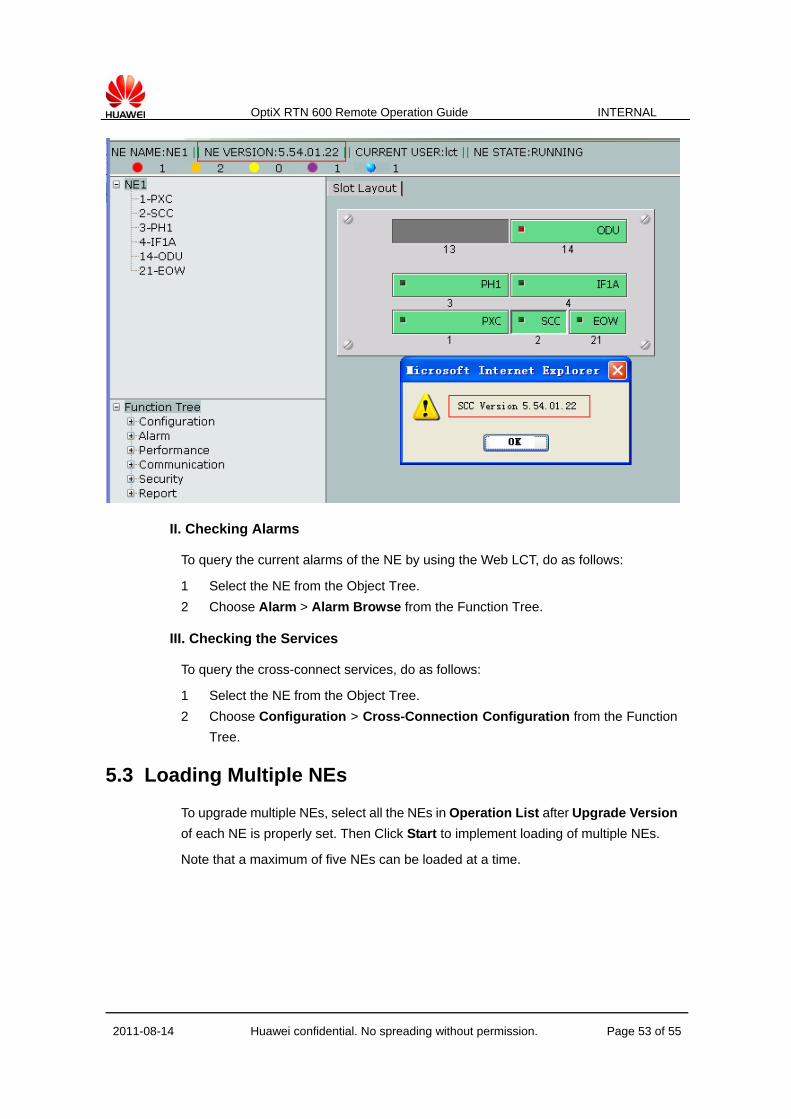
3 Log in to the NE that has been upgraded by using the Web LCT. You can view
the NE version in the NE Explorer, which is 5.54.01.22. Right-click the SCC
board in Slot Layout, and select SCC Version. Then a prompt is displayed to
read the SCC version to be 5.54.01.22. Thus the queried version is consistent
with the version to be upgraded.
OptiX RTN 600 Remote Operation Guide INTERNAL
2011-08-14 Huawei confidential. No spreading without permission. Page 53 of 55
II. Checking Alarms
To query the current alarms of the NE by using the Web LCT, do as follows:
1 Select the NE from the Object Tree.
2 Choose Alarm > Alarm Browse from the Function Tree.
III. Checking the Services
To query the cross-connect services, do as follows:
1 Select the NE from the Object Tree.
2 Choose Configuration > Cross-Connection Configuration from the Function
Tree.
5.3 Loading Multiple NEs
To upgrade multiple NEs, select all the NEs in Operation List after Upgrade Version
of each NE is properly set. Then Click Start to implement loading of multiple NEs.
Note that a maximum of five NEs can be loaded at a time.

OptiX RTN 600 Remote Operation Guide INTERNAL
2011-08-14 Huawei confidential. No spreading without permission. Page 54 of 55
After the loading is complete, select all the NEs to be activated, and choose
Advance > Activate Order to set the order for activating the NEs.
After Activate Order is set, select all the NEs to be activated, and then click the
Activate button to start activating the NEs according to the previously set order.

OptiX RTN 600 Remote Operation Guide INTERNAL
2011-08-14 Huawei confidential. No spreading without permission. Page 55 of 55
Activate the NEs in the far-to-near order based on the distance from the ECC route to
the gateway NE.