advances in electrometallurgy - pwi …pwi-scientists.com/pdf/journals/aiem201103.pdfadvances in...
TRANSCRIPT
ADVANCES IN
ELECTROMETALLURGY
CAMBRIDGE INTERNATIONAL SCIENCE PUBLISHING
No. 3 Volume 9 2011
ISSN 1810-0384
ELECTROSLAG TECHNOLOGYB.B. Fedorovskii, L.B.Medovar, A.P. Stovpchenko, V.M. Zhuravel’, V.Ya. Saenko, V.A. Zaitsev, V.B. Smolyarko and V.A. Lebed’, A new method of electroslag remelting of large hollow ingots 129S.V. Skripnik, Producing large thin-wall castings of complex shape with application of electroslag crucible melting and casting in gasified models 134
ELECTRON BEAM PROCESSESN.P. Trigug, E.A. Asnis, V.A. Berezos, A.Yu. Severin, N.V. Piskun and I.I. Statkevich, Production of intermetallic alloys of the TiAl system with boron and lanthanum additions by the method of electron beam cold hearth melting 138V.O. Mushegyan, Mathematical modelling of electron beam melting of molybdenum 142E.A. Asnis, A.B. Lesnoi and N.V. Piskun, Refining of silicon single crystals in growth by electron beam crucibleless zonal melting 147
PLASMA ARC TECHNOLOGYV.A. Shapovalov, F.K. Biktagirov, V.R. Burnashev and Yu.A. Nikitenko, Plasma arc remelting of billets, compacted from shavings of steel EP609-Sh 152D.M. Zhirov, Using plasma-arc liquid phase reduction of metals with gases for processing complex raw materials 156
GENERAL PROBLEMS OF METALLURGYV.A. Kostin, I.I. Satakevich, E.A. Asnis. G.M. Grigorenko, V.V. Lakomskii, N.V. Piskun, R.V. Kozin and V.A. Berezos, Fractographic studies of Ti-Al-(LE) alloy after zonal recrystallisation 161I.S. Malashenko, V.A. Rovkov, V.V. Kurenkova, A.F. Belyavin, D.A. Fedotov and V.K. Sychev, Increasing the cyclic endurance of single crystal blades made of ZhS36VI alloy by shot blasting the shanks of blades with microspheres 169
ELECTROMETALLURGY OF STEEL AND FERROALLOYSG.M. Grigorenko, Ya.P. Grytskiv, L.N. Chubov and A.Ya. Grytskiv, Analysis of iron ore concentrate by ESA-ICP method 181
NEW MATERIALSI.I. Maksyuta, Yu.G. Kvasnitskaya and V.V. Lashneva, Methods for producing highly refined cobalt-chromium-based alloys for medical purposes 185G.M. Grigorenko, L.G. Puzrin, M.A. Poleshchuk and A.L. Puzrin, Bimetallic materials and components produced by high-temperature non-capillary brazing 191

Editor-in-Chief B.E. Paton
Editorial BoardD. Ablitzer (France)
D.M. Dyachenko, Executive secretary (Ukraine)J. Foct (France)
T. El Gammal (Germany)M.I. Gasik (Ukraine)
G.M. Grigorenko, Deputy Chief editor (Ukraine)B. Koroushich (Slovenia)V.I. Lakomsky (Ukraine)
V. Lebedev (Ukraine)S.F. Medina (Spain)
L.B. Medovar (Ukraine)A. Mitchell (Canada)
B.A. Movchan (Ukraine)A.N. Petrunko (Ukraine)Ts.V. Rashev (Bulgaria)N.P. Trigub (Ukraine)
A.A. Troyansky (Ukraine)M.L. Zhadkevich (Ukraine)
Advances in Electrometallurgy is a cover-to-cover English translation of Sovremennaya Elektrometallurgiya, published four times a year by International Association ‘Welding’ at the E.O. Paton Electric Welding Institute, National Academy of Sciences of Ukraine, 11 Bozhenko Street, 03680 Kyiv, Ukraine
Published by
Cambridge International Science Publishing Ltd 7 Meadow Walk, Great Abington, Cambridge CB21 6AZ, England
Tel: +44 (0) 1223 893295; Fax: +44 (0) 1223 894539email: [email protected]; http://www.cisp-publishing.com
All rights reserved. This publication and each of the articles contained here are protected by copyright. Permission to reproduce materials from this journal must be obtained in writing from the Publisher

Advances in Electrometallurgy 2011 9 ( 3) 129– 133 129
A d vanc es in Elec trometallurgy 2 0 1 1 9 ( 3 ) 3 – 6T rans lated f rom Sovremennaya Elektrometallurgiya 2 0 1 1 9 ( 3 ) 1 2 9 – 1 3 3
In the last two or three years there has been a considerable interest the development of technology for the production of large hollow ingots primarily in companies operating in prepratory production in the power engineering industry. Thus, reports have been published on the technology of producing 140– 220 t hollow ingots by two world-renowned firms AREVA (France) and Sheffield Forgemasters (England). Work was started in this direction at the giant national energy and heavy engineering company Energomashspetsstal' , Kramatorsk. Similar activities are funded by the state in China. In this regard, we recall that the pioneers of heavy production of hollow ingots are the most famous Japanese companies Kobelco and Japan Steel Works (JSW), and in Ukraine the E.O. Paton Electric Welding Institute in Kiev and Zhdanovtyazhmash (now Azovmash) hollow 120 t ingots were produced more than 25 years ago. Experience with using ESR to obtain hollow ingots indicates the undoubted ben-efits of ESR of hollow ingots compared with open smelting. The Editorial Board plans to continue the publication of material on this subject, and invites its loyal readers and authors to discuss the issue.
ELECTROSLAG TECHNOLOGY
A new meth od of electroslag remelting of large h ollow ingots
B.B. Fedorovskii, L.B.Medovar, A.P. Stovpchenko, V.M. Zhuravel’, V.Ya. Saenko, V.A. Zaitsev, V.B. Smolyarko and V.A. Lebed’
E. O . P aton Elec tric W eld ing I ns titute, K iev; Elmet- R ol, K iev
Prospects for producing large-size hollow ESR ingots are considered. The possibility of melting hollow ingots by two-circuit diagram (ESR TC) using current-carrying and non-current-carrying mandrel is estimated. Comparison of different diagrams of producing hollow ESR ingots was made. The opportunity of melting hollow ingots with a change of electrodes during remelting is shown.
The application of electroslag remelting (ESM) for the production of hollow ingots started at the E.O. Paton Electric Welding Institute, Kiev many years ago. The traditional methods of this technology are still used with considerable success in the industry [ 1, 2] . With a large variety of the method, there are
two main methods of electroslag remelting of the hollow ingots. The first is realised using the so-called piercing in counter movement of the consumable electrode and the ingot with the direct electrical circuit of electrode connection.
The second method is used on a large scale

Advances in Electrometallurgy 2011 9 ( 3) 129– 133130
B . B . F ed orovs kii, et al.
and is based on the application of the bifilar electrical connection circuit of, in most cases, 6– 8 consumable electrodes.
Because of the completely understandable technical reasons, the electroslag remelting of hollow ingots was used until recently mainly for the manufacture of military objects. The weight of the ingots reached approximately 20 t, length 5– 6 m. Regardless of the high values of the physical– mechanical properties of the cast metal produced by electroslag
remelting, comparable with those of the de-formed metal, the hollow ESR ingots are used in most cases in the condition after deformation [ 3, 4] .
At present, the interest in the technol-ogy of production of hollow ingots is again considerable. This is caused by the trend to achieve maximum economic parameters. The conventional technologies of production of all types of shells, vessels and thick wall pipes are based mainly on forging from solid
Component Weight of forging, t
Parameters of solid billet for piercingDiameter, mm Length or
height, mmIngot
weight, t Y SMOuter Inner
Shaft 173.0 2710 1300 9410 290.0 59.66H ydraulic
shaft 128.0 2180 800 9150 190.0 67.37
Support ring 88.0 5530 4390 1210 130.0 67.69
Support roller 1800
× 3400110.0 1890 -
8270/3480(roll bar-
rel)182.0 60.44
Cylinder traverse 136.5 4680 1970 1190 190.0 71.84
Plate 2× 35.0 2950 2450 4650 124.5 56.22Pipe 23.0 1020 690 6500 32.7 70.33
Component
Parameters of hollow ESR billet* * Saving of metal in
melting ESR hollow billet,
t/%
Diameter, mmLength or
height, mmIngot weight,
touter inner
Shaft 2800 950 4200 185 105/36
H ydraulic shaft 2900 700 2800 140 50/26
Support ring 2800 950 2200 95 35/27Support ring 1800-3400 2300 - 3500 115 67/37
Cylinder traverse 3200 850 2400 140 50/26
Plate 2450 850 2300 75 49.5/40.0Pipe 1050 690 6500 25 7.7/27.0
* Calculated value, including allowances for losses in forging and obtained in long-term production experience* * Expert data
Table 1. The yield of suitable metal (YSM) in the production of a hollow blank by piercing from a solid ingot and its economic parameters in melting a hollow ingot by ESR

Advances in Electrometallurgy 2011 9 ( 3) 129– 133 131
A new meth od of elec tros lag remelting of h ollow ingots
forging ingots with a very low yield of suit-able metal.
Some comparative data on the efficiency of application of the hollow ingots are presented in Table 1, based on the data obtained by domestic heavy engineering plants and by expert evaluation.
The authors believe that, taking into ac-count the possibilities of ESR, it is necessary to return to discussing the potential and ad-vantages of ESR in the production of hollow ingots of very large sizes and weight. It is also assumed that the melting of hollow ESR ingots weighing approximately 300 t can be economically and technically efficient. The possibilities of producing hollow ingots of such large weight and the principles of devel-opment of appropriate eq uipment on the basis of ESR technology with direct processing of li q uid metal without consumable electrode have been published previously in [ 5, 6] .
At the same time, in connection with the need to use ESR in the shielding atmosphere for a large number of high-alloy steels and alloys, it should also be possible to produce large hollow ESR ingots and alloys by stan-dard remelting of consumable electrodes.
In the production of the large solid ESR ingots the electrodes are usually very latest during remelting. This greatly reduces the length of consumable electrode and the height of the furnace.
As indicated by practical experience, pierc-ing cannot be used for melting hollow ingots longer than 3– 4 m.
In the multi-electrode bifilar method it is very difficult to obtain the filling factor higher than 0.5 and, conseq uently, very long electrodes are req uired.
For example, at the uniq ue ESR furnace, constructed recently by the Energomash con-cern (Russia, Belgorod) it is planned to melt hollow ingots with a diameter of up to 1 m and up to 10 m long [ 7] . Thus, the melted part of the consumable electrode should be approximately 20 m long. It is fully evident that the direct application of the available solutions in this case results in an unjustified increase of the complexity of the furnace
and technology.The authors have attempted to realise the
process of ESR of hollow ingots with the re-placement of the electrodes during remelting.
The new method is based on the application of a moving current-conducting solidification mould in which the consumable electrodes are remelted by the two-circuit method, the so-called ESR TC method. Conseq uently, the consumable electrodes can be replaced with-out the risk of jamming the mandrel during upsetting of the metal or disruption of the process of formation of the ingot. In turn, the replacement of the electrodes during melting makes it possible to produce long blanks at a comparatively small column of the furnace with a low lifting capacity.
The principal diagrams of the proposed new methods of ESR of the hollow ingots are shown in Fig. 1.
The experimental melts were produced in a solidification mould with the internal di-ameter of 350 mm. The outer diameters of the current-conducting and non-conducting mandrel were the same, 114 mm.
The general power in the slag pool in both methods is 450– 500 kV· A. In melting by the method shown in Fig. 1a, the power is dis-tributed between the solidification mould and the mandrel as (300… 400):(140… 160) kV· A.
In the experiments, the parameters evaluated were the stability of the process, the symmetry of the metal pool, the q uality of the internal and external surface of the ingots, and the replacement of the consumable electrode was also simulated by short-term disconnection and extraction from the slag pool.
The results of these investigations show (Fig.2) that the stability of the process in both cases is satisfactory with the stability being slightly higher in the case of the circuit shown in Fig. 1a. The disconnection of the consumable electrodes and extraction of the electrodes from the slag pool for a period of 5 min did not disrupt the stability of the process, and after subseq uent immersion of the electrodes in the slag, melting was con-tinued in the same conditions (126… 131 min of melting, Fig. 2b).

Advances in Electrometallurgy 2011 9 ( 3) 129– 133132
B . B . F ed orovs kii, et al.
Fig. 1. The circuit of ESR TC of hollow ingots in a current-conducting solidification mould using liquid metal and a current-conducting mandrel (a) and also consumable electrode and a non-conducting mandrel (b).
Fig. 2. Recording of electrical parameters of the melts produced in accordance with Fig. 1 using liquid metal and a current-conducting mandrel (a) and also consumable electrodes and a non-conducting mandrel (b): 1) power; 2) volt-age; 3) current; 4) withdrawal rate; 5) voltage at the electrode; 6) voltage at the solidification mould; 7) current at the electrode; 8) simulation; l is the length.
Slag SlagMan
drel
Man
drel
a
b
P , kV · A U , V
t, min
U , V

Advances in Electrometallurgy 2011 9 ( 3) 129– 133 133
A new meth od of elec tros lag remelting of h ollow ingots
The macrostructure of the produce ingots was dense and homogeneous. No pores were found. The structure of the central part of the ingots was characterised by the presence of the zone of columnar crystals and by the absence of liq uation defects (Fig. 3a). No changes were found in the structure of the ingot in the zone simulating the replacement of the electrodes (indicated by the line of the profile of the liq uid metal pool).
The symmetry of the metallic pool was estimated on the basis of the position of the line of contact of the crystals, visible on the top surface of the ingot (Fig. 3b). As indicated by the figure, the position of this line is adeq uate to the position of the line on the longitudinal macrotemplate of the hollow ingot.
It should be mentioned that the circuit in Fig. 1a also has high potential possibilities for controlling the shape of the metal pool in the conditions of independent regulation of electric power (for example, when using
Fig. 3. The macrostructure of a hollow ingot melted with simulation of replacement of the electrodes; a) the shape of the metallic pool; b) the position of the line of contact of the crystal on the top surface of the ingot.
two power sources) in the circuit of the so-lidification mould and the mandrel.
Thus, the experimental results show the principal possibility of electroslag melting of long hollow ingots of high-q uality using the replacement of consumable electrodes.
References
1. Paton, B.E., et al., Electroslag casting, Naukova Dumka, Kiev, 1981.
2. Zhadkevich, M.L., et al., Sovremennaya Elektrometal-lurgiya, 2008, No. 3, 7-14.
3. Morizot, C. and Witzke, S., In: Proceedings of the International symposium on electroslag remelting technology and equipment, Kiev 2001, 131–134.
4. Medovar, B.I., et al., Spets. Elrometall., 1974, No. 26, 13–17.
5. Medovar, L.B., et al., In: Proceedings of the International symposium on electroslag remelting technology and equipment, Kiev 2001, 49–60.
6. Paton, B.E. and Medovar, B.I., Stal', 1998, No. 11, 24–27.
7. http://www.energomash.ru/2011/01/27/filial-gruppy-yenergomash-g-volgodonsk.html.
Submitted 20.07.2011
a
b

Advances in Electrometallurgy 2011 9 ( 3) 00– 00134
S. V . Skrip nik
Producing large th in- w all castings of comp lex s h ap e w ith ap p lication of electroslag crucib le melting and
casting in gasified models
S.V. Skripnik
K iev P olytec h nic al I ns titute
The technological diagram of combination of processes of crucible melting and flask full-form casting is presented. The considerable potential in combining the processes being considered are shown on the example of producing thin-walled castings with a developed surface from 20Kh20N14G2A heat resistant steel. Advantages of the pres-ent resources-saving technology consist in i ts mobili ty, high q uali ty and econo-my. The developed technology can be used for single and small-batch production.
Trays made of heat-resistant steel used smelting works operate in open heating fur-naces at high temperature (700...1100° C) with freq uent changes of temperature. Under these conditions, the q uality req uirements for blank trays are very high. At the same time, because of complex geometric shapes and a wide variety of configurations of these products, metal is usually cast into the sim-plest sand-clay moulds that do not contribute to the achievement of high q uality.
Production of metal moulds (ingot moulds) f o r s u c h p r o d u c t s w i t h a c o m p l e x form is very laborious and expensive, and in some cases impossible. To im-prove the q uality of heat-resistant trays and simultaneously increase the mobility of their production it is necessary to refine the molten metal from non-metallic inclusions, gases and contaminants in the process of electroslag crucible melting (ESCM) [ 1, 2] , and then use the flask casting mould with gasified models (CGM) [ 3– 5] .
Electroslag crucible melting with casting into an ingot mould has spread to a number of engineering companies because of its ef-ficiency. In some cases, the limiting factor is
its complexity and high cost of metal chills. LGM is a progressive way that allows to ob-tain castings with the accuracy eq ual to that of investment casting at a cost comparable to casting in sand-clay moulds.
In addition, this method can reduce the hardware costs , reduce the number of manufactur ing operat ions , us ing inex-pensive tooling. Thanks to the use as a moulding material of recycled sil ica sand and hardening the moulds with vacuum it is not necessary to rods and eq uipment for their manufacture.
The aim of this work is to study the possibility of obtaining high-q uality thin-wa l l t r ays o f complex con f igu ra t ion f r o m h i g h - a l l o y s t e e l u s i n g E S C M together with CGM.
Work was carried out in an electroslag crucible furnace eq uipped with a lined cru-cible and flasks with dry silica sand, in one of the engineering works.
The starting material used was in the form of used trays pallets of heat-resistant steel 20H 20N14G2A of a complex lattice shape with the thickness of side walls and the edges of 12 mm, weight 120 kg. Parts of used
A d vanc es in Elec trometallurgy 2 0 1 1 9 ( 3 ) 7 – 9T rans lated f rom Sovremennaya Elektrometallurgiya 2 0 1 1 9 ( 3 ) 1 3 4 – 1 3 7

Advances in Electrometallurgy 2011 9 ( 3) 00– 00 135
P rod uc ing large th in- w all c as tings of c omp lex s h ap e
trays were assemble to produce consumable electrodes (by welding).
In order to accumulate the req uired portions of liq uid metal, ESR of consumable electrodes was carried out in a crucible lined with magnesite bricks under AN-295 flux. This choice of flux is due to its acceptable melting temperature (1400...1420° C) and the content of the minimum amount (11...17% ) of chemi-cally aggressive (with respect to magnesite), calcium fluoride.
The CGM process consists of two main stages (Fig. 1). The first, based on a given drawing, products were divided into the simplest ele-ments. Depending on the position of the model in flasks, the design of the req uired riser– feeder system with dispersed supply of metal to the model was accepted.
Polystyrene plates were cut into ele-ments of products using nichrome wire 0.5 mm in diameter, through which the current of 3...5 A, adjustable by means nof a transform-er, was passed. This wire is suitable for cutting of very small contours. Its temperature reaches
250...400° C. The model was produced taking into account the shrinkage of the metal with a 2.4...2.5% allowance for machining of seats, and technological gradients that are req uired for directional solidification and feeding (Fig. 2a).
The components were assembled by adhe-sive bonding. To improve the cleanliness of the casting surface, the gasified models were covered with a layer of antiburning paint. The model was painted with a single layer with special paints by dipping into the pool. The painted model was dried in a chamber at a temperature of 40...60° C for 2 h. Painting the models helps prevent burning of the casting of and increases the strength. The coating thick-ness was 1...2 mm.
Fig. 1. Scheme of preparation and casting tray blanks.
Fig. 2. The model of the tray (a) and the blank with the gate–feeding system (b).
Production of model elements from ductile polystyrol
Production of gates and feeder heads from polystyrol
Assembly (bonding) of the model with gate-feeder system
Painting model
Placing the model in the flask
Filling with silica sand and vibrocompacting
Vacuum treatment
Pouring electroslag metal after slag skimming
Cooling casting in the flask
Extraction of casting
Cutting and cleaning the casting
Cleaning outgoing gases
Cleaning of sand
a
b

Advances in Electrometallurgy 2011 9 ( 3) 00– 00136
S. V . Skrip nik
The second stage included the instal-lation of the model in the mould, fill-i ng t he mo ld w i th d ry s and , v ib r a -tion compaction, degassing and filling. The resulting model was placed in a vertical position (Fig. 2b) in flasks eq uipped with a system for connecting a vacuum. The flask mounted on the vibroplate gradually filled with dry sand bduring vibration or in lay-ers. The thickness of the initial layer of dry sand (cushion) prior to installation of the model was 50 mm. After vibration compaction of sand the flaks was covered a plastic sheet.
The flask of a special design was subjected to evacuation prior to pouring the metal, during casting and the period of solidifica-tion. Electroslag metal was supplied after after skimming the slag which took part in in
remelting, directly to the polystyrene risers.H ot metal burns (gasifies) polystyrene
and takes his place. The released gases are sucked through a layer of paint into the sand, and then into thr vacuum system. The metal accurately reproduces the shape of the polystyrene model.
The cooling time in the casting mould was 20...25 min. After cooling, the casting of the flask was turned on a special stand-tilter at 180° . The casting (Fig. 3) and sand are usually easily removed from the mold. After extraction the gating system is cut off. The component is sandblasted to remove the rem-nants of polystyrene foam and the paint.
The resulting billet for the tray from heat-resistant steel 20H 20N14G2A of the lattice design with the thickness of the ribs of 12 mm had the overall 610× 1000× 142 mm, weight 125 kg (Fig. 4).
Testpieces of trays were tested in working conditions (Fig. 5) and showed that their strength is 50...60% higher than that of stan-dard trays, cast in sandy clay moulds.
Thus, the developed technology can be used for individual and small-scale products. In the medium-and large-scale production it uses models produced from expanded polystyrene beads with the small fraction from 0.3 to 0.9 mm by pressing in standard press moulds.
Combined applicat ion of ESCM and CGM provides mobili ty of production, high q uality and technical-econoical per-
Fig. 3. Harvesting after removal from the mold.
Fig. 4. View on trays after cleaning and machining.
Fig. 5. Pallets with blanks stamped parts prior to board-ing the heat wave.

Advances in Electrometallurgy 2011 9 ( 3) 00– 00 137
P rod uc ing large th in- w all c as tings of c omp lex s h ap e
formance of products for critical applica-t ions and with complex configuration.
References
1. Paton, B.E., et al., Electroslag casting, Kiev, Nau-kova Dumka, 1981.
2. Medovar, B.I., et al., Electroslag crucible melting and
casting of metal, Kiev, Naukova Dumka,1988. 3. Shuliak, V.S. et al., Technological and economic aspects
of casting using consumable models, Kiev, Institute of Problems of Casting, AN USSR, 1991.
4. Shinsky O., Lit. Proiz., 1991, No. 1, 4–7. 5. Shuliak, V.S. et al, The production of castings by gas-
ified models, Moscow, Metallurgiya, 2001.
Submitted 10.6.2011
Advances in Electrometallurgy 2011 9 ( 3) 138 – 14 1138
N . P . T rigub , et al.A d vanc es in Elec trometallurgy 2 0 1 1 9 ( 3 ) 1 3 8 – 1 4 1T rans lated f rom Sovremennaya Elektrometallurgiya 2 0 1 1 9 ( 3 ) 1 0 – 1 2
Production of intermetallic alloys of th e TiAl system w ith b oron and lanth anum additions b y th e meth od
of electron b eam cold h earth meltingN.P. Trigug, E.A. Asnis, V.A. Berezos, A.Yu. Severin, N.V. Piskun and I.I.
Statkevich
E. O . P aton Elec tric W eld ing I ns titute, K iev
The technology of electron beam cold hearth melting of TiAl intermetallic compound with the addition, during melting, of boron and lanthanum from lanthanum hexaboride is described. The microstructure and fractographic features of the ingots are discussed.
ELECTRON BEAM PROCESSES
In the development of advanced technology, it is necessary to produce materials capable of efficient operation in the conditions of the long-term cyclic effect of high-temperature corrosive media. A considerable reserve for increasing the values of the service char-acteristics of the structures is based on the development of alloys of intermetallic com-pounds with a high level of heat resistance and thermal stability, and also improvement of the production technology of these alloys.
The titanium alloys based on the ordered intermetallic compounds TiAl and Ti3Al rep-resent an important group of structural alloys with the uniq ue set of physical and mechanical properties. They are characterised by improved creep strength, low density, high elasticity modulus and high resistance to oxidation in
the temperature range 550– 850° C [ 1] and, conseq uently, are regarded as promising creep-resisting materials for application in aerospace technology and power engineering.
The composition of the TiAl intermetal-lics includes titanium (approximately 50% ), and also alloying elements (niobium, cerium, chromium, vanadium, etc), characterised by high chemical activity with respect to gases and impurities at elevated temperatures so that the process of melting must be carried out in a shielding atmosphere or in vacuum.
The method of electron beam melting (EBM) of the intermetallics of the TiAl and Ti3Al systems is highly promising and can result in a high degree of removal of harm-ful impurities (Fig. 1). The application of an intermediate container (cold hearth) in the

Advances in Electrometallurgy 2011 9 ( 3) 138 – 14 1 139
P rod uc tion of intermetallic alloys of th e T iA l s ys tem
ELECTRON BEAM PROCESSES
electron beam melting support refining, aver-ages the chemical composition and removes the inclusions with high and low density [ 2] . The process of production of the ingots of the g-titanium aluminide by electron beam melting was described in detail in Ref. 3.
The low ductility (less than 1% ) at room temperature [ 4] greatly complicates the tech-nological processing of intermetallic alloys and is the main obstacle in the extensive application of these alloys in the industry. At present, work is being carried out to determine the alloying elements for the alloys based on TiAl and Ti3Al intermetallic compounds, capable of increasing their plasticity.
To improve the plasticity properties of the TiAl intermetallic system, the main alloying element added in a small amount (from 0.1 to 0.5 wt.% ) is boron which increases the transition temperature to the single-phase a-region and the reduces the transition tem-perature from the single phase a-region to the two-phase a+b-the region, i.e., is a b-stabilising element [ 5] .
In electron beam melting it is difficult to introduce boron to the molten TiAl inter-metallic compound because under the effect of electron beam heating during melting of boron characterised by high vapour tension in melting the extent of evaporation of boron is very high and also the particles are displaced and removed when boron is introduced into the charge in the form of powder. Therefore, this is carried out using lanthanum hexaboride LaB6 characterised by a considerably lower
vapour tension in melting in comparison with boron. Lanthanum reduces the extent of evaporation of boron.
In addition, this method can also be used to add lanthanum that of the melt and this also increases the elasticity of the melted inter-metallic compound in hot deformation [ 6] .
The aim of the present work is the inves-tigation and development of a technology for producing ingots of Ti-28% Al– X intermetallic alloy (X = Nb, Zr, Cr) with additional al-loying with boron and lanthanum in electron beam cold hearth melting (EBCH M).
The experimental melts of the ingots of TiAl intermetallic compound with a diam-eter 165 mm were produced in eq uipment UE-208M. The charge consisting of VT1-0 titanium alloy, commercial purity aluminium, electrolytic chromium, niobium and zirco-nium was remelted. Titanium hexaboride was added to the charge in the form of cylindri-cal compacts produced by pressing of the LaB6 powder in a special pressing mould. The completed compacts of the lanthanum hexaboride were placed between the refrac-tory components of the charge in order to avoid direct effect on them of electron beam heating and the possibility of evaporation. In preparation of the charge the alloying ele-ments with high vapour tension (chromium and aluminium) were supplied taking into account the evaporation losses.
After loading the charge, the eq uipment is evacuated. At the beginning, the charge is poured into the cold hearth and subseq uently the liq uid metal is periodically poured into a copper water cooled solidification mould (Fig. 1) to produce the ingot of the req uired length.
Figure 2 shows the produced ingot.The composition of the TiAl intermetallic
alloy was determined by chemical analysis. Samples were taken along the ingot at a depth of 10 mm from the surface, and in the radial direction (across the ingots) at radii of 70, 50 and 30 mm. Three zones were investigated: upper, lower and the middle of the ingot. The lanthanum content was determined in the same zones by spectral analysis. The results of chemical analysis of the TiAl intermetallic
Fig. 1. The process of melting TiAl intermetallic compound.
g

Advances in Electrometallurgy 2011 9 ( 3) 138 – 14 114 0
N . P . T rigub , et al.
compound, alloyed additionally with boron and lanthanum, are presented in Table 1.
The microstructure of the ingots with the additions of boron and lanthanum (Fig. 3a) and without these conditions (Fig. 3b) was investigated.
In most cases, the microstructure of the intermetallic alloys based on g-TiAl+a2-Ti3Al is characterised by elongated colonies of the ductile structures, and the length of these colonies and the spacing between them control the plasticity properties of the intermetal-lic compounds and also the nucleation and propagation of cracks in the material during cooling.
The microstructure of the TiAl ingots, without any boron, consists of (g + a2) the ductile colonies with the precipitates of the b-phase by the grains are considerably larger with the length of the lamellae up to 40 µ m and the spacing between them 5.7 µ m.
The addition of a small amount of the loan to the alloy reduces the size of the colonies (the length of the lamellae and the distance between them). In solidification, the alloy forms fine-dispersion borides (mostly TiB2 [ 5,7] ) which can both refine the microstruc-ture of the ingot and also efficiently delay the growth of grains in heating in the -range, especially after hot deformation.
The examination of the microstructure of the ingot it is typical for the cast alloy of the intermetallic compound and consists of fine grains with ductile colonies (g+a2) with the mean length of the lamellae of 25 µ m and the distance between them being 2.7 µ m, light layers of the b-phase and the dark areas of the g-grains, distributed along the boundaries of the colonies. Q uantitative x-ray spectrum microanalysis shows that the light regions are enriched with niobium which is a b-stabiliser. It may be assumed that the detected light phase is the b-phase.
The results of metallographic examination shows that the addition of 0.1 wt.% of boron to the alloy reduces the length of the lamel-lae of the ductile colonies and the distance between them by approximately a factor of two. In addition to this, investigations in the JEOL scanning electron microscope by fractographic methods of the specimens of TiAl intermetallic compound without and with boron additions shows that the specimens of the intermetallic compound, containing boron, have the fracture surface consisting of a flaky structure with separation ridges, characteristic of the ductile component. The fracture surface of the specimens with no boron showed a distinctive transcrystalline river-like fracture by the cleavage mechanism,
Fig. 2. Ingot of the TiAl intermetallic alloy after double remelting.
Sample No.Mass fraction of elements, %
Al Nb Zr Cr Ti1 30.2 10.89 2.99 3.01 55.82 28.3 11.26 3.07 2.87 55.63 28.8 11.85 3.22 2.87 55.7
Comment. The composition of TiAl intermetallic in each sample also in-cluded 0.1 B and 0.01
Table 1. Chemical composition of TiAl intermetallic alloy

Advances in Electrometallurgy 2011 9 ( 3) 138 – 14 1 14 1
P rod uc tion of intermetallic alloys of th e T iA l s ys tem
Sample No.Mass fraction of elements, %
Al Nb Zr Cr Ti1 30.2 10.89 2.99 3.01 55.82 28.3 11.26 3.07 2.87 55.63 28.8 11.85 3.22 2.87 55.7
Comment. The composition of TiAl intermetallic in each sample also in-cluded 0.1 B and 0.01
Table 1. Chemical composition of TiAl intermetallic alloy
typical of brittle fracture.Figure 4 shows the fractographs of the
fracture surfaces of the specimens of TiAl intermetallic alloy with boron and lanthanum (Fig. 4a) and without them (Fig. 4b).
Thus, the technology has been developed and experimental melts of the ingots of the intermetallic alloy of the TiAl were produced by the EBCH M method, and the results of metallographic studies show the promising nature of using this method for producing high-q uality ingots of titanium aluminide, alloyed with boron and lanthanum.
Fig. 3. Microstructures (× 500) of the TiAl intermetallic alloy, alloyed with boron and lanthanum (a) and without alloying (b).
Fig. 4. Fractographs (×220) of the fracture surfaces of TiAl intermetallic compound, alloyed with boron lanthanum (a) and without them (b).
References
1. Ivanov, V.I., et al., Tekhnol. Legkikh Splavov, 1996, No. 3.
2. Paton, B.E., et al., Electron beam melting of refractory and high-reactivity metals, Naukova Dumka, Kiev, 2008.
3. Zhuk, G.V., et al., Sovremennaya Elektrometallurgiya, 2003, No. 4, 20-24.
4. Mikhailov, S.I., et al., Aviats. Promst., 1991, No. 4, 37–39.
5. Imaev, R.M., et al., Fiz. Met. Metalloved., 2006, No. 1, 114–122.
6. Povarova, K.B., et al., Metally, 1998, No. 3, 31–40.7. Savitskii, E.M. and Terekhova, V.F., Physical metallurgy
of rare-earth metals, Nauka, Moscow, 1975.
Submitted 20.5.2011
a b
a b
Advances in Electrometallurgy 2011 9 ( 3) 14 2– 14 614 2
V . O . M us h egyan
Table 1. Chemical composition of the ingots of molybdenum in electron beam cold hearth melting and of the initial material [2]
Typ e of p roductMass f raction of elements, %
C S F e Cu O N
Metallic molybdenum in the form of sintered brique ttes (TSh 64-15126592-02:2008)
0.1 0.01 0.5 0.01 1.0 _
Metallic molybdenum in the form of sintered brique ttes (according to the analysis results)
0.005 0.001 0.2 0.01 0.1 0.03
Ingots produced by electron beam cold hearth melting, diameter 70 and 100 mm
0.002 < 0.001 0.007 < 0.001 0.0005 0.002
A d vanc es in Elec trometallurgy 2 0 1 1 9 ( 3 ) 1 4 2 – 1 4 6 T rans lated f rom Sovremennaya Elektrometallurgiya 2 0 1 1 9 ( 3 ) 1 3 – 1 6
Math ematical modelling of electron b eam melting of molyb denum
V.O. Mushegyan
P aton- A rmeniya Sc ientif ic and T ec h nic al C entre, E. O . P aton Elec tric W eld ing I ns titute, K iev
Mathematical model and calculation program were developed for determination of conditions of molybdenum ingot melting into a water-cooled mould. Basing on the experimental data, the coefficients of eq uations of heat transfer problems were determined. The model allows optimizing the process EBCH M of molybdenum using the peripheral heating of ingots in the mould.
tribution of the heat flow with local concentration in the vicinity of the wall of the solidification mould to maintain the cylindrical shape of the metal pool ensuring favourable conditions of forma-tion of the surface of the ingot;
– uniform distribution of the heat flow in the central part of the pool surface for the formation of a flat solidification front with the given level of the axial temperature gradients along the height of the liq uid metal pool creates suitable conditions in which the solidifying metal is characterised by the high homogeneity of the physical properties [ 1] .
The E.O. Paton Electric Welding Insti-tute, Kiev is carrying out work to improve the technology of EBM of molybdenum. Analysis of the properties of the experi-mental ingots shows that in remelting mo-
Electron beam melting (EBM) is one of the promising methods of producing ingots of refractory metals, in particular molybdenum.
This metallurgical process is characterised by the following advantages:
– remelting is carried out in vacuum which prevents the contact of metal with the chemically active atmosphere and also prevents contamination of the remelted material;
– the presence of a developed free surface of the melt subjected to long-term hold-ing in the intermediate container (cold hearth) and in the solidification mould, supports the processes of evaporation and degassing;
– the application of the electron beam source of heating makes it possible, as a result of scanning the surface with the beam, to control efficiently the dis-

Advances in Electrometallurgy 2011 9 ( 3) 14 2– 14 6 14 3
M ath ematic al mod elling of elec tron b eam melting of molyb d enum
The technological scheme of the EBM of a cylindrical ingot using the cold hearth is shown in Fig. 2.
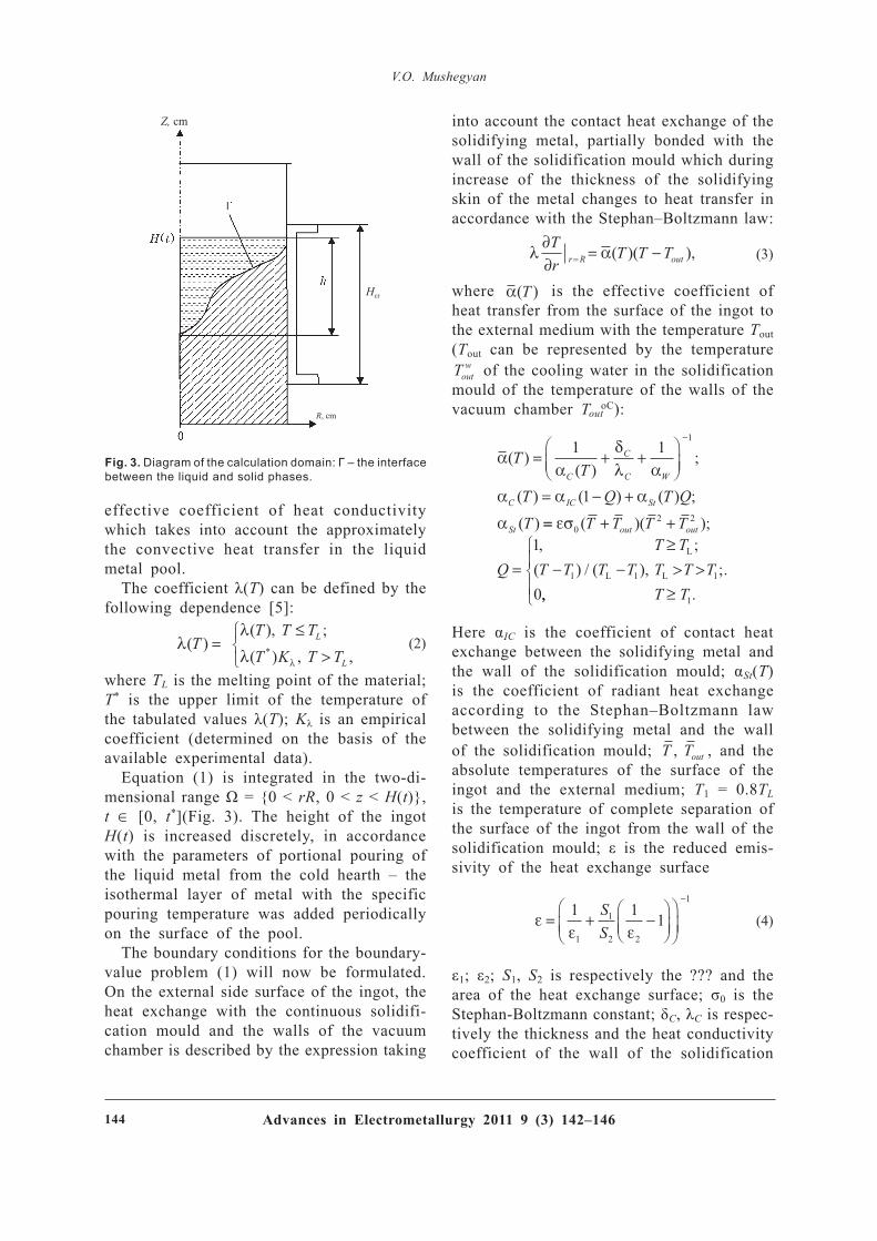
The formulation of the mathematical model of solidification of metal in the cylindrical solidification mould assumes the axial sym-metry of the thermal processes. Therefore, the three-dimensional problem was reduced to solving the two-dimensional problem in the cylindrical coordinates (Fig. 3).
Taking into account the assumptions of the axial symmetry of the heat field, the thermal state of the ingot in EBM of molybdenum is described by the following eq uation [ 4] :
∂∂
= ∂∂
∂∂
+ ∂∂
+ ∂∂
Wt r r
r T Tr z
T Tr
1 λ λ( ) ( ) , (1)
where W = W ( T ) is enthalpy; ( T ) is the
lybdenum in a vacuum of approximately 1 × 10– 2 Pa the application of the cold hearth reduces the mass fraction of impurities (Table 1) and the mechanical properties of the material improve (Fig. 1).
These experimental data provide q uantitative estimates of the level of the properties obtained in electron beam melting of molybdenum. In addition to this, it is also interesting to investigate the possibilities of improving the q uantitative and q uantitative parameters of the remelted material. The availability of this information makes it possible to determine the rational range of the technological parameters in the EBM of molybdenum ingots.
The range of the data which can be obtained is limited by the need to carry out expensive and time-consuming full-scale experiments which provide insufficient information on the parameters of solidification of the remelted material.
To optimise the process of obtaining the data, instead of using the experimental results it is more rational to use the method of math-ematical modelling of the physical processes taking place during EBM of molybdenum.
Therefore, the main task of the present study is the formulation of a mathematical model for investigating the processes of heat exchange and solidification in the EBM of molybdenum, evaluate the q uantitative and q ualitative parameters of both the remelting conditions and the solidification conditions of the remelted material.
Fig. 1. Temperature dependence of the ultimate strength of molybdenum tubular blanks, produced from ingots of different melts: 1) EBM; 2) electron beam cold hearth melt-ing with peripheral heating of the solidification mould [3].
δt, MPa500400300200100300
400
500
600
700
T, °C
Fig. 2. Technological diagram of electron beam remelting of a cylindrical ingot: 1) electron beam heaters; 2) remelted metal; 3) cold hearth; 4) solidification; 5) solidified ingot.
Advances in Electrometallurgy 2011 9 ( 3) 14 2– 14 614 4
V . O . M us h egyan
effective coefficient of heat conductivity which takes into account the approximately the convective heat transfer in the li q uid metal pool.
The coefficient λ( T ) can be defined by the following dependence [ 5] :
λλ
λ λ
( )( ), ;
( ) , ,*TT T TT K T T
L
L
=≤
>
(2)
where T L is the melting point of the material; T * is the upper limit of the temperature of the tabulated values λ( T ); K λ is an empirical coefficient (determined on the basis of the available experimental data).
Eq uation (1) is integrated in the two-di-mensional range Ω = {0 < rR , 0 < z < H (t)} , t ∈ [ 0, t * ] (Fig. 3). The height of the ingot H (t) is increased discretely, in accordance with the parameters of portional pouring of the liq uid metal from the cold hearth – the isothermal layer of metal with the specific pouring temperature was added periodically on the surface of the pool.
The boundary conditions for the boundary-value problem (1) will now be formulated. On the external side surface of the ingot, the heat exchange with the continuous solidifi-cation mould and the walls of the vacuum chamber is described by the expression taking
into account the contact heat exchange of the solidifying metal, partially bonded with the wall of the solidification mould which during increase of the thickness of the solidifying skin of the metal changes to heat transfer in accordance with the Stephan– Boltzmann law:
λ α∂∂
= −=Tr
T T Tr R out( )( ), (3)
where α( )T is the effective coefficient of heat transfer from the surface of the ingot to the external medium with the temperature T out ( T out can be represented by the temperature Tout
w of the cooling water in the solidification mould of the temperature of the walls of the vacuum chamber T out
oC):
αα
δλ α
α α α
α
( )( )
;
( ) ( ) ( ) ;
( )
TT
T Q T QT
C
C
C W
C IC St
St
= + +
= − +
−1 1
1
1
== + +
=≥
− − > >
εσ02 2
1 1 1
1
0
( )( );, ;
( ) / ( ), ;.
T T T T
QT T
T T T T T T T
out out
L
L L
,, .T T≥
1
Here α I C is the coefficient of contact heat exchange between the solidifying metal and the wall of the solidification mould; αSt( T ) is the coefficient of radiant heat exchange according to the Stephan– Boltzmann law between the solidifying metal and the wall of the solidification mould; T Tout, , and the absolute temperatures of the surface of the ingot and the external medium; T 1 = 0.8 T L is the temperature of complete separation of the surface of the ingot from the wall of the solidification mould; ε is the reduced emis-sivity of the heat exchange surface
εε ε
= +
1 1 1
1
1
2 2
1SS
−−
(4)
ε1; ε2; S1, S2 is respectively the ? ? ? and the area of the heat exchange surface; σ0 is the Stephan-Boltzmann constant; δ C , λ C is respec-tively the thickness and the heat conductivity coefficient of the wall of the solidification
Fig. 3. Diagram of the calculation domain: Γ – the interface between the liquid and solid phases.
Z, cm
Hcr
R, cm

Advances in Electrometallurgy 2011 9 ( 3) 14 2– 14 6 14 5
M ath ematic al mod elling of elec tron b eam melting of molyb d enum
mould; α W is the coefficient of heat transfer from the surface of the solidification mould wall to the cooling water.
Outside the limits of the solidification mould it is assumed that δ1 is eq ual to 0, and α W is infinitely greater in comparison with αSt( T ).
The boundary conditions on the bottom surface of the ingot are described by analogy with the eq uations (3), (4).
On the free surface of the metal pool, the resultant heat flow is expressed by the relationship
λ α∂∂
= = − +Tz
z H T T T q r tt t h( ) ( )( ) ( , ),S out (5)
where q h (r, t) is the specific density of the heat flow in the electron beam heating of the pool surface.
At the initial moment of time, it is as-sumed that the cavity of the solidification mould contains a seed volume of the metal with the given temperature T 0 = T L. Calcula-tions are carried out obtaining the req uired height of the ingot, corresponding approxi-mately to 2 ingot diameters resulting in the formation of the steady thermal state of the liq uid metal pool.
The numerical realisation of the mathemati-cal model of EBM of molybdenum was carried out using the finite difference method [ 6] .
The handbook [ 7] presents the initial values of the physical characteristics and technologi-cal parameters, included in the description of the mathematical model of formation of the molybdenum ingot in electron beam melting.
Comparison of the results, obtained in the calculations using the reference key param-eters, with the data obtained in the full-scale experiments on a legal technological object can be used to verify the model [ 8 ] and determine the average characteristics of the process parameters which can be obtained by direct measurement on the basis of indirect information.
Tech nological p arameters of meltingIngot diameter D , cm 70– 100Superheating of poured metal above T L , Δ T , oC 50
Req uired height of the cylindrical part of liquid metal pool Δ h r, cm 0.2The height of the solidification mould H C , cm 15The final height of the ingot Z , cm 150
The reference data obtained from the ex-perimental melts of EBM molybdenum, used for the determination of the information on the coefficients of heat exchange of the side surface of the ingot with the solidification mould, the walls of the vacuum chamber, the baseplate, and also the surface of the metal pool with the walls of the vacuum chamber are as follows:
Given ref erence values of th e tech nological p arameters of meltingIngot diameter D , cm 7 10The height of the portion of poured metal Δ h Z , cm 4.5 3.5Duration of the break between pouring cycles Δ h Z , min 2Thermal power of central heating W 1, kilowatt 20 40Thermal power of peripheral heating in the vicinity of solidification mould W 2, kilowatt 40 40Ratio of the radii of the central and peripheral heating rW 1/ R 0.8 0.7
Given ref erence conditions of solidif ication of th e ingotIngot diameter D , cm 7 10Depth of the pool at the axis of the ingot ( h r = 0), cm 0.6 0.6H eight of the cylindrical part of the pool ( h r = R ), cm 0.2 0.2
Figure 4 shows the calculated thermal state of the ingot of EBM molybdenum for the steady geometry of the liq uid metal pool.
The average values of the emissivity of the surfaces were selected to ensure that the calculated values of the kinetics of the temperature of the reference points differs only slightly from the experimental values.
The calculation show that at the given ref-erence parameters of the melting of the data on temperature measurements on the internal

Advances in Electrometallurgy 2011 9 ( 3) 14 2– 14 614 6
V . O . M us h egyan
surface of the solidification mould and on the surface of the bottom plate obtained using tungsten– rhenium thermocouples, connected to a KSP-4 recording device; on the surface of the liq uid using a PPT-131 optical parameter ‘Smotrich’ at reference points, the average values of the coefficients are as follows:
Calculated dataIngot diameter D , cm 7 10Reduced coefficient of emissivity of the surface on the pool surface ε1 0.5Effective coefficient of partial contact heat exchange on the side surface of the ingot in the upper zone of the solidification mould in the cylindrical part of the metallic pool, α C , W/cm2· ° C 0.2Reduce coefficient of emissivity on the external side surface of the ingot within the limits of the solidification mould in the zone of complete separation from the wall of the solidification mould, eC 0.8Reduced emissivity coefficient on the external side surface of the ingot below the solidification mould eS 0.5Effective coefficient of heat exchange on the bottom surface of the ingot α B , W/cm2· ° C 0.01
The identified data can be used for further calculations and optimisation of the kinet-ics of the thermal state of the molybdenum ingot in EBM.
Conclusions
1. The mathematical model of electron beam melting of molybdenum in a copper watercooled solidification mould was devel-oped and applied in the form of a program.
2. The experimental melts of molybde-num ingots with a diameter of 7 and 10 cm were used as an example for confirming the adeq uacy of the mathematical model, and determination of the empirical coefficients of the main eq uations of the salt problem.
References
1. Flemmings, M., Processes of vacuum solidification, Mir, Moscow, 1977.
2. Mushegyan, O., Sovremennaya Elektrometallurgiya, 2009, No. 4, 26-28.
3. Mushegyan, O., Elektrometallurgiya, 2010, No. 9, 28–31.
4. Tikhonov, A.N. and Samarskii, A.A., Equations of mathematical physics, Nauka, Moscow, 1966.
5. Medovar, B.I., et al., Thermal processes in electroslag remelting, Naukova Dumka, Kiev, 1978.
6. Samarskii. A.A., The theory of difference schemes, Nauka, Moscow, 1977.
7. Kikoin, I.K. (editor), The tables of physical quantities, Atomizdat, Moscow, 1976.
8. Marchuk, G.I., Methods of computing mathematics, Nauka, Moscow, 1989.
Submitted 20.7.2011

Advances in Electrometallurgy 2011 9 ( 3) 14 7 – 15 1 14 7
A d vanc es in Elec trometallurgy 2 0 1 1 9 ( 3 ) 1 4 7 – 1 5 1T rans lated f rom Sovremennaya Elektrometallurgiya 2 0 1 1 9 ( 3 ) 1 7 – 2 0
Refining of silicon single crystals in growth by electron b eam crucib leless z onal melting
E.A. Asnis, A.B. Lesnoi and N.V. Piskun
E. O . P aton Elec tric W eld ing I ns titute, K iev
Experimental and design data about refining of silicon single crystals in their growth by the method of electron beam crucibleless zonal melting are presented. It is shown that with use of this method it is possible to reduce the oxygen concentration by two orders, phosphorus by one and a half orders as compared with that of the initial material, produced by the Czochralski method. Using the computational experiment the regularities of formation of the concentrated state of the produced single crystal were investigated. It is shown that the main factors determining the refining characteristics are the processes of evaporation and degassing in vacuum.
Electron beam crucibleless zonal melting (EBCZM) is one of the promising methods of producing single crystal silicon with a low content of impurities and a high level of the homogeneity of the physical properties.
This metallurgical process is characterised by a number of advantages: remelting is car-ried out in vacuum preventing contamination of the specimens with the crucible material; the presence of a well-developed free surface of the molten zone supports the processes of evaporation and degassing; the application of the ring-shaped electron beam heat source makes it possible, as a the result of scan-ning the surface with the beam, to control flexibly the distribution of the heat flow for the formation of a flat solidification front, resulting in the formation in the volume of the single crystal with the high homogeneity of the physical properties [ 1] .
Oxygen and phosphorus are the most char-acteristic impurities in silicon [ 2] . The pres-ence of oxygen in the specimen has a negative effect on the electrophysical properties of silicon [ 3] . Phosphorus is one of the main
alloying components and its content should correspond to the req uired concentration level [ 4 ] . The possibility of reducing the mass fraction of oxygen and ensuring the req uired phosphorus content are the main factors which determine the efficiency of the process of zonal recrystallisation for producing single crystal silicon.
The E.O. Paton Electric Welding Institute, Kiev has been carrying out experiments with the refining of silicon single crystals by the EBCZM method. Analysis of the properties of the remelted specimens shows that in the zonal melting in a vacuum of 2.66· 10– 3 Pa (approximately 2· 10– 5 torr) the mass fraction of oxygen is reduced by two orders of mag-nitude, from 3· 1017 to 5· 1015 at/cm3 (measure-ments were taken by infrared spectroscopy) of phosphorus by a factor of 1.5, from 5.1· 1014 to 3.4· 1013 at/cm3 (the method of electron paramagnetic resonance). The increase of the specific electrical resistance by approximately 14 times (the method of four-probe measure-ment of the specific electrical resistance) is a complex indicator of the level of purification

Advances in Electrometallurgy 2011 9 ( 3) 14 7 – 15 114 8
E. A . A s nis , et al.
of the silicon single crystal which can be achieved using the EBCZM method.
The experimental data can be used for the q uantitative evaluation of the param-eters which can be achieved by the EBCZM method. In addition to this, it is interesting to investigate the mechanisms and relationships ability determine the refining parameters. The availability of this information makes it pos-sible to estimate the possibilities of refining silicon and the rational range of the techno-logical parameters of the EBCZM method.
The possibilities of obtaining the req uired data are limited by the need to carry out expensive and time-consuming full-scale ex-periments providing very limited information on the relationships governing the formation of the concentrated state of the remelted material.
To obtain the req uired data, it is not ra-tional to combine the available results of the experiments with mathematical modelling of the physical processes taking place during the EBCZM method.
The application of this approach greatly reduces the number of full-scale experiments and also reveals the hidden relationships of the processes taking place. This cannot be achieved without the experimental methods. Thus, the main task of the present study is the development of a mathematical model of the processes of mass exchange and the ap-plication of these models to investigate the possibilities of refining of the single crystal silicon by the EBCZM method.
In the formulation of the mathematical model it was proposed that the cylindrical specimens with radius R and length L (Fig. 1) is characterised by the constant height of the molten zone L v, which moves along the specimen with the constant velocity v in such a manner that the speed of movement of the solidification front ξ(t) is constant and eq ual to the melting rate of the initial specimen with the initial concentration C 0.
In the melt, in the vicinity of the solidifica-tion front, the diffusion layer with the length δ forms and is enriched with the liquating impurity as a result of the movement of the
solidification front (the mass transfer within the limits of the diffusion layer is determined by the diffusion transfer mechanism). Outside the limits of the diffusion layer along the entire height of the molten zone L v there is sufficiently intensive convective mixing for complete homogenisation of the melt.
Taking into account the accepted assump-tions, the concentration state of the remelted specimens in the EBCZM method is deter-mined by the kinetics of mass balance in the molten zone as follows:
V dCdt
q q S q S
q D dCdl
q v C C
q C
zd m R L
dl t
m z
o
= +( ) +
=
= −( )=
= +
α
ξ δ
α
σ
α
;
;
;( )
0
uut zC−( ), (1)
where V is the volume of the molten zone; C is the concentration of the impurity in the diffusion layer; C z is the concentration of the impurity in the vicinity of the boundary of the diffusion layer of the molten zone; t is time; q d is the mass flow arriving in the molten zone from the diffusion layer; D is the diffusion coefficient; q m is the mass flow, travelling into the core of the liq uid zone as a result of melting of the initial specimen with concentration C 0; q α is the mass flow from the free surface of the molten zone; α is the surface mass exchange coefficient which takes into account degassing (evaporation) of
Fig. 1. Diagram of the calculation region.

Advances in Electrometallurgy 2011 9 ( 3) 14 7 – 15 1 14 9
R ef ining of s ilic on s ingle c rys tals
the dissolved component in vacuum; C out is the residual concentration of the impurity in vacuum; SR , SL are the areas of respectively the cross-section and the side surface of the molten zone.
The following conditions of redistribution of the masts were taken into account at the solidification boundary:
D dCdl
v k C
C kCl t
l t
s l t l t
==
= =
= −( )
=
ξξ
ξ ξ
( )( )
( ) ( )
;1
where k is the coefficient of redistribution of the dissolved component in the transfer of material from the liq uid to the solidified condition; C S is the concentration of the impurity in the solidified material, adjacent to the solidification front.
The mass transfer from the solidification boundary to the molten zone in the bound-ary diffusion layer of the given length is described by the diffusion eq uation
∂∂
= ∂∂
< < +Ct
D Cl
t l t2
2 , ( ) ( ) .ξ ξ δ (2)
It was assumed that diffusion mass trans-fer in the solidified material can be ignored. At the initial moment of time, the chemical composition of the specimen along the entire length is uniform with the given concentra-tion C (l, 0) = C 0.
The mathematical model described here was used to setup software for modelling the kinetics of mass exchange processes and predicting the formation of a chemical het-erogeneity along the length of the specimen in relation to the physical characteristics of the material and the technological parameters of the EBCZM method.
The following parameters of the model were used in the calculations: length of the specimen 10 cm, the height of the molten zone 1 cm; the coefficient of diffusion of the components in the melt 5· 10– 5 cm2/s; the length of the diffusion boundary layer 0.2 cm; the distribution coefficient 0.54 oxy-gen, 0.035 for phosphorus; the value of the
coefficient α was determined on the basis of the experimental data in the determination of the content of the impurity in the specimens prior to and after remelting. The calculated results are presented in the form of the rela-tive concentration C = C ¯ / C 0 where C ¯ , C 0 is the true and initial concentration, respectively.
Two processes were used in refining the specimen in EBCZM: redistribution of the dis-solved component at the solidification front as a result of differences in the solubility of the impurity in transfer of the material from the liq uid to the solidified state and evaporation (degassing) in vacuum from the free surface of the melt. The dominant refining mecha-nism was determined by the calculations in which both the separate and combined effect of these two factors was taken into account.
Figure 2 shows the distribution of the oxygen and phosphorus concentration along the length of the solidified section of the specimen in relation to the melting rate (δ = 0.2 cm, L v = 1 cm) without considering the process of evaporation (degassing) in vacuum.
The results, shown in Fig. 2, shows that with the variation of the rate of recrystallisa-tion, the purification of silicon as a result of different solubility of the impurities in the liq uid solidified material does not make it possible to reduce the concentration of oxygen in a single pass by more than 0.5 orders of magnitude (0.5 C 0) at a high nonuniformity of the distribution of the impurities along the length of the specimen (0.5 … 0.9 C 0), and phosphorus by 0.8 orders of magnitude (0.2 C 0).
The experimental results show the relatively uniform distribution of the impurities and the reduction of the mass fraction of oxygen by two orders of magnitude, and the mass frac-tion of oxygen by 1.5 orders of magnitude. Therefore, calculations were carried out to determine the efficiency of the process of evaporation (degassing) in vacuum which can take place with different intensity depending on the pressure of the residual gases in the vacuum chamber, the height of the molten zone, superheating of the free surface above the liq uidus temperature, and other factors.

Advances in Electrometallurgy 2011 9 ( 3) 14 7 – 15 115 0
E. A . A s nis , et al.
Figure 3 shows a series of calculations, showing the reduction of the oxygen con-centration of the molten zone and in the solidified section of the specimen in relation to the different values of coefficient α.
Calculation show that the reduction of the mass fraction of oxygen by two orders of magnitude is achieved at α = 0.1 at/cm2s. In this case, uniform distribution of the im-purities along the length of the solidified part of the specimen is achieved (Fig. 3b), with the exception of the initial short sec-
tion. The identical calculations carried out for phosphorus shows that the reduction of the initial concentration by a factor of 1.5 corresponds to 0.5 at/cm2 s.
Conclusions
1. A mathematical model of zone recrystal-lisation has been developed and can be used to investigate the formation of the concentra-tion state of the specimen as a result of the differences in the solubility of impurities in
Fig. 2. Effect of the recrystallisation rate v on the redistribution of the impurity: a) oxygen; b) phosphorus; 1-5) the values of 1·105, 1·10–4, 5 ·10–3, 1·10–2 m/s).
Fig. 3. Concentration state of the liquid zone (a) and the solidified specimens (b) at different values of the coefficient of vacuum degassing of oxygen: 1-5) 0, 0.1·10–4, 1·10–3, 1·10–2, 1·10=1 at/cm2 s).
C , wt.% C , wt.%
C , wt.% C , wt.%

Advances in Electrometallurgy 2011 9 ( 3) 14 7 – 15 1 15 1
R ef ining of s ilic on s ingle c rys tals
the liq uid and solidified materials, and also the processes of evaporation in vacuum.
2. The experimental results show that the EBCZM method makes it possible to reduce the oxygen concentration by two orders from 3· 1017 to 5· 1015 at/cm2, and the phosphorus concentration by 1.5 orders (from 5.1· 1014 to 3.4· 1013 at/cm3).
3. The calculation show that as a result of the difference in the solubility of the impurity in the solid and li q uid state the concentration of oxygen can reduced in a single pass by no more than 0.5 orders (0.5 C 0) and the phosphorus concentration by 0.8 orders (0.2 C 0).
4. It was also shown that the dominant factor which ensures the reduction of the mass fraction of oxygen by two orders of magnitude and that of phosphorus by 1.5 orders in the EBCZM method are the pro-
cesses of degassing and evaporation in the vacuum in the presence of a well-developed free surface of the molten zone.
5. The coefficients of surface mass ex-change taking into account the gassing (evaporation) of the dissolved component in EBCZM in processing vacuum of 2.66· 10– 3 Pa (approximately 2· 10– 5 torr) – for oxygen 0.1 at/cm2 s, and phosphorus 0.5 at/cm2 s, were determined.
Ref erences
1. Asnis, A.E., et al., Kosmichna Nauka Tekhnol., 2002, No. 5/6, 112–116.
2. Gerasimov, Ya.I., Lectures in physical chemistry, volume 1, Khimiya, Moscow, 1969.
3. Landau, L.D. and Lifshits, E.M., Theoretical physics, volume 5, Statistical physics, Nauka, Moscow, 1976.
4. Kunin, L.L., et al., Problems of degassing of metals (phenomenological theory), Nauka, Moscow, 1972.
Submitted 11.4.2011

Advances in Electrometallurgy 2011 9 ( 3) 00– 0015 2
Sh ap ovalov, V . A . , et al.A d vanc es in Elec trometallurgy 2 0 1 1 9 ( 3 ) 1 5 2 – 1 5 5T rans lated f rom Sovremennaya Elektrometallurgiya 2 0 1 1 9 ( 3 ) 2 1 – 2 3
Plasma arc remelting of b illets, c omp acted f rom sh avings of steel EP609- Sh
V.A. Shapovalov, F.K. Biktagirov, V.R. Burnashev and Yu.A. Nikitenko
E. O . P aton Elec tric W eld ing I ns titute, K iev
The results are presented of experiments carried out to investigate plasma-arc remelting of billets compacted from shavings of EP609-Sh creep-resisting steel. The technological special features of remelting are determined and ingots were produced in casting into a mould and melting in a continuous solidification mould. The chemical composition and the q uality of the resultant ingots are determined.
PLASMA ARC TECHNOLOGY
Gas turbine engines (GTE), used as the power systems of gas pumping aggregates, are produced from corrosion-resisting steels and alloys. The Zorya-Mashproekt company, specialising in the manufacture of the GTE, produces the rotors of compressors of low- pressure engines DN80L and DG90 from EP609-Sh steel [ 1] . In the case of sufficiently high corrosion resistance, the steel can be efficiently machined and welded by electron beam and argon-shielded arc welding. This is important in the assembling of the rotor from the individual components.
The increase in the volume of production of components from the steel resulted in buildup of waste in the plant, especially in the form of shavings. Conseq uently, it is necessary to utilise this waste efficiently.
One of the promising methods of processing the shavings of high alloy steels is the technol-ogy of compacting under electric current in a
continuous matrix into long billets [ 2] which are then processed by remelting by special electrometallurgy processes. The method was developed at the E.O. Paton Electric Welding Institute, Kiev. The second, refining stage, is essential for producing high-q uality metal suitable for direct application in production.
Experiments were carried out with the electroslag remelting of consumable billets produced by compacting the shavings of EP609-Sh steel [ 3] . In the present work, the results are presented of another method of refining remelting of the compacted shavings - plasma arc remelting (PAR). The main refining component in ESR is the slag melt, and the q uality of metal is determined by the mass exchange processes in the slag– metal system. A special feature of PAR is that refining is carried out as a result of the distribution of the elements in the gas– metal system.
The possibility of remelting the metal at

Advances in Electrometallurgy 2011 9 ( 3) 00– 00 15 3
P las ma- arc remelting
PLASMA ARC TECHNOLOGY
normal or even excess pressure in an inert atmosphere enables plasma arc remelting of
billets with increase the degree of gas satura-tion or a high content of elements with high vapour tension without disrupting the process and large losses of the alloying elements dur-ing evaporation. H igh-temperature plasma-arc heating can be used to produce billets with a satisfactory surface, a high yield of suit-able metal and a low content of gases and non-metallic inclusions.
The compacted abilities remelted in a four-plasma torch multifunctional furnace UPP-4 [ 4 ] . The direct action plasma torches are
Fig. 1. Diagram of plasma arc remelting in casting into an ingot mould: 1) copper watercooled crucible; 2) two pairs of direct current plasma torches; 3) the column with the mechanism for supplying the consumable billets; 4) con-sumable billets; 5) the ingot mould; 6) the skull layer, which forms on the surface of the cold crucible during melting.
Fig. 2. Preparation of UPP-3 equipment for melting of the consumable blank in a continuous solidification square mould.
Fig. 3. Plasma-arc remelted ingots, 120 × 120 × 155 mm.
a b

Advances in Electrometallurgy 2011 9 ( 3) 00– 0015 4
Sh ap ovalov, V . A . , et al.
deposition in the radial direction so that the plasma jets are directed to the liq uid metal pool and form vortex rotation of the melt. The level of current in each plasma torch is 350 A, voltage approximately 40 V. Melting was carried out in argon with an excess pres-sure of 10– 20 kPa and constant circulation of the gas, and also with the renewal of the atmosphere in the chamber.
The radial distribution of the four plasma torches results in the distribution of the ther-mal load on the surface of the pool and enables staring of the pool and regulation of heating of the individual zones of the pool (especially peripheral areas).
An important advantage of the radial distri-bution of the plasma torches with the screen-ing by the billets of radiation of plasma jets and the pool. In the final analysis, the billet receives a large proportion of radiation thus reducing the energy req uired for melting.
In melting, the billet, secured to a column with a displacement mechanism, is supplied between four plasma torches. Entering the zone of action of the plasma arc, the billet melts and as a result of droplet transfer the metal falls into the liq uid pool.
The billets, compacted from the shavings, are subjected to 2 types of remelting. The first is based on the remelting of the billet with the buildup of liq uid metal in the crucible and its subseq uent discharge into a casting mould (ingot moulds), the second one is based on remelting of the billet in a copper watercooled solidification continues mould with a sq uare section of 125 × 125 mm.
The diagram of plasma arc remelting using the first type of remelting is shown in Fig. 1. For the second method of plasma arc re-melting, the UPP-three furnace was modified and the rotating crucible was replaced by a solidification mould (Fig. 2). In this case, the billet is withdrawn from the solidifica-tion mould using a lower bar which carries a water-cooled baseplate with a dove connec-tion. The billet is secured on the baseplate and in the process of plasma arc remelting moves together with the plate. The rate of withdrawal of the ingot is matched with the
rate of supply of the blank into the melting zone. It is eq ual to 3– 4 mm/min.
In the process of remelting, a small slag layer forms on the surface of the metallic melts and on the side surfaces of the billets. This indicates the transfer of non-metallic inclusions from the remelted blank into the slag phase.
Smooth regulation of the power of the plasma torches makes it simple to produce a dense s q uare billet almost without any shrinkage cavity (Fig. 5). The general specific consumption of electric energy in remelt-ing is approximately 2.0-2.2 kW· h/kg, and in industrial application and increase of the cross-section of the billet this consumption can be reduced.
Visual examination of the surface of the plasma-arc remelted billets, produced in the continuous solidification mould and cast into the ingot moulds, did not show any large defects of the type of skin folds, cracks, excees metal, etc. The macrostructure of the produced metal is dense and homogeneous (Figs. 4, 5), and there are no pores, liq uation or other defects.
The chemical composition of the produced ingots fully corresponds to the req uirements of plant technical conditions for the EP609-Sh steel. For comparison, Table 1 gives the results of chemical analysis of the same metal after electroslag remelting of the blanks compacted from these shavings [ 3] .
Fig. 4. Microstructure (× 500) of the plasma-arcremelted ingots with casting into an ingot mould.

Advances in Electrometallurgy 2011 9 ( 3) 00– 00 15 5
P las ma- arc remelting
Attention should be given to the lower carbon and silicon content in the plasma-arc remelted metal, in comparison with the ESR metal, and also a lower gas content (oxygen, hydrogen and nitrogen), by 20– 30% . At the same time, plasma remelting was characterised by a higher content of chromium and sulphur. This is explained by the special features of refining of the metal and the occurrence of mass exchange processes in these types of
Remelting method
Mass fraction of elements, %C Si Mn P S Cr Mo Ni Nb V
PAR 0.017...0.02 0.23...0.25 0.30...0.35 0.025 0.02 11.2...11.4 0.4 1.67...1.70 0.1 0.2
ESP 0.084...0.088 0.39...0.52 0.29...0.30 0.03 0.002 10.8...11.00 0.4 1.61...1.64 0.007 0.2
TUU-27-1-00190414-030-2004
0.05...0.09 < 0.6 < 0.6 < 0.03 < 0.02 10.5...12.0 0.35...0.5 1.4...1.8 0.05...0.15 0.15...0.25
Table 1. Chemical composition of the EP 609-Sh creep-resisting alloy
Fig. 5. Macrostructure of the cross-section of a square billet of EP690-Sh steel produced by plasma arc remelting in a continuous solidification mould.
melting processes.Thus, it may be concluded that the method
of plasma arc remelting makes it possible to remelt efficiently the billets produced by compacting of shavings of EP609-Sh a steel with retention of the chemical composition of the metal and improvement of its q uality as a result of the reduction of the gas content and the content of nonmetallic inclusions. The selection of the method of processing these billets (plasma arc remelting, electroslag remelting, or other processes) depends on the specific req uirements on the metal from which components will be produced.
References
1. Romanov, V.V. and Koval', V.A., Using new materials in conversion of sheep and aviation gas turbine engines into stationary gas turbine systems, Vost. Evrop. zh-l Pered. Tekhnol., 2010, No. 3/2, 4–7.
2. Paton, B.E., et al., Patent 79977, Ukraine, Method for compacting charge, MPK C 22 B 1/248, 10.08.2007.
3. Shapovalov, V.A., et al., Sovremennaya Elektrometal-lurgiya, 2009, No.3, 43-45.
4. Zhadkevich, M.L., et al., Sovremennaya Elektrometal-lurgiya, 2005, No. 3, 64-67.
Submitted 17.6.2011

Advances in Electrometallurgy 2011 9 ( 3) 15 6 – 16 015 6
An effective method for producing metals from oxide materials, including technogenous waste, is the reduction of these materials with carbon during melting [ 1, 2] . The degree of reduction of iron reaches 97% , chromium 96% , nickel 100% . This is accompanied by the relatively complete interaction of a number of metals and by carburisation of the product. To produce high-percentage ferroalloys or enriched slacks from ‘poor’ starting material, it has been proposed to carry out selective reduction by the addition of a limited amount of the reduction agent. Suitable examples are the production of ‘the rich’ ferronickel from oxidised nickel ores [ 3] , titanium slag from ilmenite concentrate [ 4 ] , and the conver-sion manganese slag with a low phosphorus content [ 5] .
H ydrogen and carbon monoxide at high temperatures are inferior to carbon as regards the reduction potential but they can be used for the liq uid phase reduction of both iron [ 6, 7] and also metals from the complex raw materials [ 8, 9] . In the latter case, the lower reduction capacity of the gases, in comparison with carbon, supports selective reduction [ 9] .
The E.O. Paton Electric Welding Institute, Kiev, has been investigating the process of plasma-arc liq uid phase interaction of iron with gaseous reduction agents from the iron ore starting material from the Krivoi Rog deposit [ 10] . In the experiments, the reduc-
tion agents were the products formed in the plasma of the arc as a result of pyrolysis or air conversion of hydrocarbons, supplied into the reaction space as the plasma forming gases.
In contrast to the technologies in which carbon is used as the reduction agent, in this process, in addition to iron, the reduction of other elements, in particular silicon, is not used widely and there is no carburisation of the product. This indicates that the proposed process makes it possible to carry out selec-tive reduction of the metals from the complex of the materials with the formation of low carbon ferroalloys or enriched slags.
At the experiment temperature of approxi-mately 2000 K [ 10] , the value of the Gibbs energy for the reactions of reduction of iron from its monoxide by carbon, hydrogen and carbon monoxide is respectively – 136.2; +13.9 and +38.5 kJ/mole [ 11] . In this case, the eq uilibrium constants of the reactions are eq ual to 3500; 0.43 and 0.1. This shows that almost the entire amount of carbon, present in the melt, reduces the iron, whereas hydro-gen, in particular carbon monoxide, interact incompletely.
The main impur i ty inc luded in the composi t ion of the i ron ore s ta r ing mate r ia l i s s i l i con . The var ia t ion o f t he G ibbs ene rgy a t 2000 K in t he reduction with carbon, hydrogen and carbon monoxide is respectively – 2.5; +33 and +39
Using p lasma- arc liq uid p h ase reduction of metals w ith gases f or p rocessing comp lex r aw materials
D.M. Zhirov
The efficient method of production of metals from oxide materials, including technogeneous
The feasibility of selective reduction of metals from complex raw materials by different re-ducing agents is considered. A diagram of producing ferronickel from Pobuzhsk oxide-bearing nickel ores, demonstrating the advantages of use of gaseous reducing agents, is offered.
A d vanc es in Elec trometallurgy 2 0 1 1 9 ( 3 ) 1 5 6 – 1 6 0 T rans lated f rom Sovremennaya Elektrometallurgiya 2 0 1 1 9 ( 3 ) 2 4 – 2 7
E. O . P aton Elec tric W eld ing I ns titute, K iev

Advances in Electrometallurgy 2011 9 ( 3) 15 6 – 16 0 15 7
P las ma- arc liq uid p h as e red uc tion of metals
kJ/mole [ 11] . The eq uilibrium constant is 1.16; 0.14 and 0.1. Thus, if the melt contains a large amount of iron oxide, the reduction of silicon and its transfer into the metal do not develop extensively, as confirmed by laboratory investigations [ 10] .
The variation of the Gibbs energy of the reactions of reduction of nickel with carbon, hydrogen and carbon monoxide at a tempera-ture of 2000 K corresponds to the values – 223; – 73 and – 48.3 kJ/mole. The eq uilibrium constant of the reactions is 633500; 80 and 18, i.e., the reduction of nickel is more likely to take place and the reduction of iron [ 11] .
More than 80% of exploited world reserves of nickel have the form of oxidised ores [ 3, 12] , with the nickel content of 1...2% . The main components of the charge are the oxides of iron and silicon. The extraction of nickel from this ore is carried out using two groups of methods. The first method is the hydrometallurgical leaching using sulph-uric acid or ammonia, the second method is based on the metallurgical methods: Electric melting using matte (75% NiS) which is then baked to NiO and used to metallic nickel, or electric melting (in some cases blast furnace melting) for the production of ferronickel. In the latter case, the carbothermal reduc-tion of both nickel and iron takes place. As a result of the high concentration of iron in the ore and a low nickel concentration, the nickel content of the ferroalloy is low. The consumption of electric energy for pro-cessing 1 t of ore is approximately 0.8 or 80 MW· h per 1 t of nickel in the ferroalloy at the nickel content of the ore of approxi-
mately 1% [ 3, 9, 12] .By reducing the amount of supplied elec-
tion agent it is possible to reduce the extent of transfer of iron into the ferroalloy. In the processing of the ore from Pobuzsk deposit, the mass fraction of the nickel increases from 4.5 to 29.5% , but the extraction of nickel decreases from 93.5 to 68.8% [ 3] . It should be mentioned that after the reduction of nickel from the melt, it is efficient to re-duce steel semifinished products in a separate system. Conseq uently, the iron content of the residual slag decrease cease to 11.6% which is similar to this concentration in the slag in the production of the ‘poor’ ferronickel by the conventional method. In this case, the extraction of nickel is complete.
The Institute of Metallurgy of the Uralsk Division of the Russian Academy of Sciences found that in a blowing a reduction gas into the ore melt it is possible to produce a metal with 40...60% of nickel with the degree of extraction of nickel of approximately 80% [ 9] . This confirms the high efficiency of the selective reduction with the gas in comparison with carbon.
The possibi l i ty of carrying out this process will be examined in greater de-tail on the example of production of fer-ronickel from the Pobuzsk oxidised nickel ore with the following composition, % : 0.86… 0.96 Ni; 23.3… 36.6 SiO2; 4.9… 8.9 A l 2O 3; 23 .3 … 34 .5 Fe 3O 4; 0 . 91 … 1 . 44 CaO; 3.93… 6.59 MgO; 1.28… 7.16 Cr2O3; 0.017… 0.076S; 0.021… 0.061 P; 0.047… 0.0 89 Co; 4.12… 7.94 H 2O; losses in baking 6.74… 8.84.
Fig. 1. Diagram of the production of ferronickel at the Pobuzsk Ferronickel Plant.
Ore, limestone,reduction agent
Natural gas
Outgoing gas
Hot stub
ORF
Electricenergy Slag
(removalof S)
Crude ferronickel
Soda
Desulphu-rization
Crudeferronickel
Oxygen
“Acid”converter
Removal ofSi, Cr, C, S
Crudenickel
Oxygen
‘Basic’converter
Ferronickel(to 25% Ni)Removal of
P, C, S
Reduction annealingin TRF
Gases, dust(removal of
P and S)

Advances in Electrometallurgy 2011 9 ( 3) 15 6 – 16 015 8
D . M . Z h irov
The current method of production of the fer-roalloys at the Pobuzhsk Ferronickel Company is shown in Fig. 1 [ 3, 12] . After drying in a tu-bular rotating furnace (TRF) the nickel ore in mixture with the reduction agent and limestone is supplied into the tubular rotating furnace for reduction baking.
These furnaces were initially heated with mazut but now they have been converted to a mixture of natural gas and the gas out go-ing from the ore reduction furnace (ORF) of the gases [ 13, 14] . From the rotating tubular furnace, the hot material is loaded into the ORF with a power of 50 MW with six self-sintering electrodes with a diameter 1.2 m.
The resultant crude ferronickel usually con-tains (wt.% ) up to 10 Si, 3 Cr, 1.5 C, 0.4 S and 0.3 P [ 3] . In the ladle, it is purified to remove sulphur using soda and subseq uently in the converters with the acid and a base lining it is also purified to remove different impurities.
At a high degree of extraction of nickel iron is also extensively reduced and, conse-q uently, the mean concentration of nickel in the ferroalloy was 6% in the production of the ferroalloys from natural ore. This was the reason why the company changed to imported ore with the Ni content of approximately 2% and, conseq uently, its concentration in the ferroalloy increased to 20% [ 13, 14] .
Because of the low nickel oxide content in the slag, the following reaction is impor-tant for its reduction in the production of ferronickel [ 3] :
(NiO) + [ Fe] = [ Ni] + (FeO).
Thus, for the reduction of nickel it is im-portant to have high activity of iron in the melt. At high temperatures, these metals are characterised by the existence of a continuous series of solid solutions [ 15] , and their melt should be close to ideal [ 16] . Experiments showed the negative deviation of the Fe– Ni system from the Raoult law [ 3] .
Iron with silicon form intermetallic phases [ 15] , which result in the large negative de-viation of the Fe– Si system from the Raoult law [ 3, 16] . The reduction of the activity of
iron in the melt is also supported by carbon because carbide formation takes place [ 3, 16] . The application of the gas reduction agents makes it possible to avoid the extensive reduc-tion of silicon from the slag and carburisation of the metal and, conseq uently, ensures high activity of iron in the melt.
The reduction of silicon from the slag melt can be influenced by adding to it calcium oxide because this is accompanied by the for-mation of calcium silicate and, conseq uently, the activity of the silicon oxide decreases and that of the iron oxide increases [ 17] . For example, when using gaseous reduction agents with other conditions being eq ual, the addition of CaO from the iron ore starting material increases the degree of extraction of iron from 65 to 90% , and that of silicon decreases from 0.12 to 0.03% [ 10] . The de-gree of extraction of iron and nickel from the oxidised nickel ore also increases [ 8] .
The selective reduction with the gaseous reduction agents makes it possible not only to produce a ferroalloy with a high nickel content from the ‘lean’ raw material but also avoid large degrees of reduction of silicon, chromium and phosphorus so that it is not necessary to carry out refining of the product to remove these elements (Fig. 2).
It should be mentioned that the main source of sulphur in the produced ferronickel is the reduction agent (in most cases anthracite). Evidently, as a result of the application of
Fig. 2. Production of ferronickel by the proposed method.
Ore, limestone
Outgoing gas
??????
ORFFerronickel(40-60% Ni)
Ferrous slagGases, dust(removal of
P, S)
Annealing of TRF
Electric energy,natural gas, dust
H otstub
Annealing in TRF

Advances in Electrometallurgy 2011 9 ( 3) 15 6 – 16 0 15 9
P las ma- arc liq uid p h as e red uc tion of metals
the gaseous reduction agent in the proposed process there is no carburisation of the fer-roalloys and the latter will also have a lower sulphur content. For example, in the case of plasma-arc liq uid phase reduction of iron with the gases from the raw material of the Krivoi Rog deposit, the carbon concentration of the product was approximately 0.02 and that of sulphur 0.007 wt.% [ 10] .
In the proposed method, it is possible to use dust-like charge materials [ 18, 19] and, conseq uently, the problem of utilisa-tion of the nickel containing dust can be solved without pelletising of the dust. It should be taken into account that because of the low nickel concentration in the ore the efficiency of application of the gas reduction agents in the productivity of the process and greatly affected by the supply of the reagents to the reaction zone. The supply of the dust-like charge by the reduction gas into the arc zone is an effective solution of this problem.
The selective reduction is used for pro-ducing enriched slags. In Ukraine, there are very large reserves of the ilmenite ore (FeO · TiO2) [ 20] . In the production of titanium or ferrite titanium, even after enriching, the ilmenite concentrate contains more than 40% of iron oxides. For the production of titanium sponge it is necessary to produce a slag containing no less than 80% of tita-nium oxides and no more than 5% of iron oxides [ 4, 21] .
Enrichment of the slag with the titanium oxides takes place as a result of selective reduction of iron oxides from ilmenite in an ore thermal furnace. For this purpose, a carbon-containing reduction agent, in most cases milled coke, is added to the charge.
The iron oxides are reduced more efficiently by carbon than the titanium oxides because the variation of Gibbs energy at 2000 K for the reduction of titanium by carbon is +11.8 kJ/mole [ 11] .
In the melting of the titanium slag, to pre-vent the transfer of titanium to the metallic phase, the content of the carbon-containing reduction agent in the charge is selected slightly smaller in comparison with the theo-
retically necessary content for the complete reduction of the iron oxides.
According to the thermodynamic data, the reduction of titanium with hydrogen and carbon monoxide does not take place (the variation of the Gibbs energy at 2000 K is respectively +312 and +362 kJ/mole [ 11] ) so that it is possible to carry out more extensive management of the slag by reduction of iron with gases.
Of special interest is the processing of the complex raw materials in which both the enriched slag and the reduced metal are important. A suitable example of this type of material are the iron-manganese concretions which together with iron and manganese also, and copper, nickel, cobalt and other elements. In particular, because of the high content of the impurity elements, special interest has paid to the development of these deposits on the seabed [ 5, 22] .
One of the variants of processing of this type of material is used for preliminary selec-tive solid-phase reduction of copper, nickel and cobalt with hydrogen (up to 90% ), and partially iron (60– 70% ) and the almost com-plete retention of manganese in the form of oxides.
The melting of metals takes place by electric melting of the product of reduction without addition of the reduction agent. This results in the formation of a complex alloy with the total copper, nickel and cobalt content higher than 20% , and also in the formation of a conversion slag with the manganese concentration of 34– 35% . In comparison with manganese, phosphorus can be easily reduced and almost completely is transferred into the metal, and its content in the slag is less than 0.015% [ 5, 22] .
The proposed method of plasma-arc liq uid phase interaction with gases makes it possible to realise the combine process of melting of iron-manganese concretions and the se-lective reduction of the elements with low affinity for oxygen. The application of the gases leaving the melting space for heating and preliminary solid-phase reduction of the raw material improves the efficiency of the

Advances in Electrometallurgy 2011 9 ( 3) 15 6 – 16 016 0
D . M . Z h irov
3. Gran' N.I., et al., . Electric melting of oxidized nickel ores, Metallurgiya, Moscow, 1971.
4. Zhadkevich M.L., et al., Sovremen. Elektrometall., 2005, No. 1, 12-16.
5. Belichko B.F., et al., Manganese metallurgy in Ukraine, Kiev, Tekhnіka, 1996..
6. Velichko B.F., et al., Coke-free metallurgy of iron, Dnipropetrovsk, PVA Dnipro-VAL, 2002.
7. Kirpichev D.E., et al., Stal',2007, No. 9, 41-44.8. Gimmel'farb A.A., et al., in: Plasma processes in metal-
lurgy and technology of inorganic materials: Proc., Moscow, 4-6 October, 1988. 9. Leont'ev L.I., et al., Stal', 2003, No. 11, 19-21.10. Zhirov D.M., Special features of plasma arc liquid phase
reduction on iron with gases, Dissertation,E.O. Paton Electric Welding Institute, Kiev, 2011.
11. Grigorian V.A., et al., Theoretical foundations of electric steelmelting processes, Metallurgiya, Moscow, 1987.
12. Gasik M.I., et al., Theory and technology of the pro-duction of ferroalloys, textbook for high schools Metal-lurgiya, Moscow, 1988.
13. http://www.rada.com.ua/rus/catalog/14362/.14. http://krashiy.com/rus/nominations2008/?nid=40&id=1 4362 & pid = 1008 & sd =.15. Lyakishev N.P. (editor), Diagrams of binary metallic
systems, handbook, Moscow, Mashinostroenie, 1997. 16. Medzhibozhsky M.Ya. Fundamentals of thermodynamics
and kinetics of the steelmaking process, Kiev, Donetsk Vishcha shk, 1986.
17. Elliott, D.F., et al. Thermochemistry of steelmaking processes, Metallurgiya, Moscow, 1969.
18. Lezhava K.I., et al., Probl. Spets. Eleltrometall., 2000,No. 4, 38-44.
19. Zabarilo O.S., et al., Ibid, 1998, No. 4, 38-48.20. Kulish E.A.,et al., Deposits of metal ores and their
integrated use, Kiev, Institute of Environmental Geo-chemistry, 2008.
21. Garmata V.A., et al., Metallurgy of titanium, Metal-lurgiya, Moscow, 1967..
22. Gasik M.I., Geologiya Polez. Iskop. Mir. Okeana, 2005, No. 1, 34-50.
Submitted 30.6.2011
proposed process [ 10] .As a result of the exhaustion of the re-
serves of raw materials and the increase of the demand for elements, it is necessary to regard many raw material deposits of Ukraine as complex ores [ 20] . The reduction melting with the application of gaseous reduction agents maybe an efficient means for process-ing this type of material.
Conclusions
1. The experimental results show that the lower production capacity of carbon monoxide and hydrogen, in comparison with carbon, in application for the selective reduction makes it possible to produce ferroalloys and slags with higher content of these elements.
2. It has been established that the ap-plication of the gaseous reduction agents produces products with a low concentration of impurities. Conseq uently, in many cases it is possible to avoid refining operations.
References
1. Grigorenko G.M., Kostyakov V.N. Physicochemical processes in plasma-arc remelting oxide-containing materials, Current problems of materials science, Vol.1, Kiev, Akademperiodika, 2008, 379-393.
2. Yasins'ka O.O., Investigation of liquid-phase reduc-tion of metal melting and technology development for casting alloys from oxide-containing materials, FTIMS NANU, Kiev, 2009.

Advances in Electrometallurgy 2011 9 ( 3) 16 1– 16 4 16 1
A d vanc es in Elec trometallurgy 2 0 1 1 9 ( 3 ) 1 6 1 – 1 6 4T rans lated f rom Sovremennaya Elektrometallurgiya 2 0 1 1 9 ( 3 ) 2 8 – 3 0
F ractograp h ic studies of Ti- Al- ( LE) alloy af ter z onal recrystallisation
V.A. Kostin, I.I. Satakevich, E.A. Asnis. G.M. Grigorenko, V.V. Lakomskii, N.V. Piskun, R.V. Kozin and V.A. Berezos,
E. O . P aton Elec tric W eld ing I ns titute, K iev
The results of fractographic studies of Ti-Al-(LE) titanium aluminide in the initial condition and after zonal recrystallisation are presented.
GENERAL PROBLEMS OF METALLURGY
The intermetallic alloys based on titanium aluminide are characterised by high creep strength, heat resistance and corrosion re-sistance and, conseq uently, are regarded as promising materials for application in the production of turbines of aircraft engines and other components for aerospace technology.
The main shortcoming of these alloys is the low ductility at room temperature. This greatly complicates processing and industrial application. The studies directed to increasing the plasticity of these materials are associated both with the development of new alloys based on titanium aluminide and the development of various technological processes increasing the ductility of the alloys [ 1] .
The ductility characteristics of a cast inter-metallic alloy can be improved by the zone recrystallisation. The application of zone melt-ing makes it possible to ensure directional
crystallisation [ 2] . If the melting technology is correctly selected, the solidification front is almost flat. This results in the more uniform distribution of admixtures in the cross-section and the volume of the ingot and also reduces the level of the stress state and this together should increase the plasticity of the material.
Fractographic studies were carried out on specimens of the intermetallic alloy of the TiAl system with the following composition, wt.% : 46.5 Ti, 35 Al, 12.5 Nb, 3 Zr, 3 Cr, produced by the method of electron beam melting with a cold hearth (EBCH ) [ 3] .
Fractographic studies were carried out in a JSM-35F scanning electron microscope, fit-ted with INCA-450 analysis eq uipment. The samples, produced by the EBCH method in the initial condition and after zonal recrystal-lisation were studied.
The experimental results show that the frac-

Advances in Electrometallurgy 2011 9 ( 3) 16 1– 16 416 2
V . A . K os tin, et al. ,
ture of the specimens of the initial metal is mixed. In particular, and examination shows the distinctive transcrystalline river-like frac-ture by the cleavage mechanism, characteristic of brittle fracture (Fig. 1a).
In addition to this, the fracture surface showed signs of ductile fracture – light fi-brous ridges, indicating the variation of the direction of movement of the crack. Since this procedure uses part of the fracture en-
Fig. 1. The fracture surface of different areas of the alloy in the initial condition: a, b) × 200; b) × 480.
Fig. 2. The surface of fracture areas of the alloy after zonal recrystallisation, × 200.
ergy, maybe assumed that the material has a certain fracture resistance and, conseq uently, a certain level of ductility.
In addition to this, the fracture surface contained micropores. Cleavage fracture com-bined with the micropores is the characteris-tic mechanism of failure of titanium a2 and (a+g2) alloys. The single-phase region of the grain, with the axes oriented parallel to the axis of the acting stress, the stresses were high and normal to the cleavage planes and, conseq uently, they failed by cleavage [ 4] . The grains with different orientation are af-fected by lower stresses. These grains are subjected to plastic deformation and failed by the ductile mechanism.
Figure 1b shows the fracture of the different area of the initial material. H ere, as in Fig. 1a, examination showed brittle transcrystal-line failure of the material by the cleavage
a
b
c
a
b

Advances in Electrometallurgy 2011 9 ( 3) 16 1– 16 4 16 3
F rac tograp h i c s tud ies of T i – A l – ( L E) alloy
mechanism. The same specimen also showed pure elongated areas indicating that the cracks propagated along the grain boundary.
Figure 1c shows another area of the fracture surface of the initial material. H ere, there is a number of ductile steps parallel to each other. This pattern is typical of brittle fracture of the intermetallic compound Ti3Al (a2). These steps are directed in one direction. Usually, at fracture, these ductile parallel steps form on the needle-shaped particles of the a2-phase.
Fractographic studies of the specimens, remelted in a high-freq uency electromagnetic field, show that the fracture surfaces differ from those of the initial material.
Fracture surfaces (Fig. 2a) show a flaky structure with separation ridges, characteristic of the ductile component. After zone remelt-ing, the fracture surface contained bent fibrous steps, randomly distributed on the fracture area. In particular, the appearance of the flaky steps on the fracture surface supports the development of ductile failure and this explains the increase of plasticity.
The formation of the smooth large facets is evidently determined by plastic shearing.
Analysis of the results of fractograph-ic studies shows that the specimens of the intermetallic compound, subjected to zone remelting, are characterised by the mixed fracture – transcrystalline and intercrystal-line. In contrast to the initial specimens, in this case, the fracture area shows large zones with the ductile component.
In addition to this, analysis of the results of the fractographic studies shows (Fig. 2b) the presence of areas where the fracture mechanism in different grounds with the same, there are striations of brittle fracture with the parallel direction greatly changing in the adjacent grains. As the number of changes in the direction of failure increases, the ductility of the material also increases. The branched steps on the fracture surfaces of the investigated specimens also indicate the ductility of the material.
The presence of the ductile component on the fracture surface may also be explained by the stability of the a2-phase as a result
of supersaturation with niobium which is a strong stabiliser of the b-phase. In addition to this, the alloy studied in this work also contains other b-stabilisers, in particular, ce-rium and chromium, supporting the formation of the b-phase. The presence of this phase in the alloy results in the development of ductile failure and increases the plasticity characteristics [ 5] .
The presence of the areas of intercrys-talline fracture of the alloys may also be caused by the precipitation of the a2-phase of different dispersion at the boundaries of the b-grains [ 6] .
The INCA-450 analyser was used to cal-culate the fraction of the ductile component (on the basis of the brightness threshold) in the specimens prior to and after zonal recrystallisation (Fig. 3).
In the specimens, subjected to zonal re-crystallisation, the amount of the ductile component was 16% greater than that of the
Fig. 3. Diagram showing the distribution of the ductile brittle components in the field of the specimen in the initial condi-tion (a) and after zonal recrystallisation (b); A) the area of the entire specimen; I) the region of the brittle component (95.6 and 78.3%, respectively); II) the area of the ductile component (5.5 and 21.6%, respectively).
a
b

Advances in Electrometallurgy 2011 9 ( 3) 16 1– 16 416 4
V . A . K os tin, et al. ,
initial specimens produced by EBCH method (the amount of the ductile component of the material in the initial condition was 5.5% , and after zonal remelting 21.6% ).
Changes in the structure, taking place in the process of zonal recrystallisation, have a positive effect on increase of the plasticity at room temperature. In the tensile test of the specimens of the alloy at 20° C the plasticity increased approximately 3 times (from 0.8 in the initial material to 2.2% after zonal recrystallisation).
Conclusions
1. Fractographic studies of the fracture surfaces of the intermetallic alloy specimens shows that the initial material is character-ised by brittle transcrystalline fracture by the cleavage mechanism.
2. The experimental results show that the fracture surfaces of the specimens of the
intermetallic compound after zone recrys-tallisation are of the mixed type with the dominance of plastic failure.
3. It was also shown that the zonal recrys-tallisation of the titanium aluminide of the Ti– Al– Nb– Zr– Cr system increases the amount of the ductile component on the fracture surface by 16.1% in comparison with the initial material.
Ref erences
1. Anatashov, V.G., et al., Tekhnol. Lehkikh Splavov, 2002, No. 4, 72–76.
2. Lakomskii, V.V., et al., Zonal recrystallisation of titanium aluminide, Proc. Titan v SNG 2010, St Peterburg, 2010, 132–139.
3. Paton, B.E., et al., Electron beam melting of refractory and high-reactivity metals, Naukova Dumka, Kiev, 2008.
4. Bochvar, A.G. et al., Metalloved. Term. Obrab. Met., 2008, No. 3, 30–40.
5. Povarova, K.B. and Bannykh, O.A., Materialovedenie, 1999, No. 2, 27–32.
6. Povarova, K.B., et al., Metally, 1998, No. 3, 31–41.
Submitted 24.3.201

Advances in Electrometallurgy 2011 9 ( 3) 16 5 – 16 8 16 5
M ec h anis m of nitrid ing liq uid metal
According to many investigators, the slag is not permeable to nitrogen. Therefore, in the presence of a liq uid slag, for example, in electroslag remelting, it is not possible to alloys the metal with nitrogen directly from the gas phase. Thus, the metal can be alloyed with nitrogen, according to these investiga-tors, only by introduction into the metallic melts of nitriding ferroalloys or nitrides of alloying elements [ 1, 2] . Some investigations indicate the possibility of nitriding the metal in electroslag remelting in relation to the resultant melting conditions [ 3] .
The transport of nitrogen through the slag is referred to as the gas permeability, which is determined by the product of the limiting solubility of nitrogen in the slag C N and the coefficient of diffusion of nitrogen in the slag D N [ 4– 6] :
ПN = C N D N
The solubility of nitrogen in the slags has been determined by almost all investigators in investigating the gas – slag binary sys-tem. H owever, nitrogen permeability assumes the transfer of nitrogen from the gas phase through the slag of the metal in the gas– slag-metal ternary system. This conclusion has appeared on the basis of the investigations
by the authors of the present article into the solubility of nitrogen of the gas phase in the calcium fluoride and nitrogen saturation of the metal situated below the layer of liq uid fluoride.
Not all nitrogen and results in the fluoride, and the metal situated below the fluoride is nitriding. This means that this dependence does not describe accurately the process of nitrogen permeability.
Examination of the ternary system has shown that the transport properties of the slag depend on the thermodynamic conditions, formed not only at the gas– slag boundary but also at the slag– metal boundary. It is therefore necessary to take into account not only the solubility of nitrogen in the slag but also the driving force of the entire process of transfer of nitrogen from the gas to the metal represented by the difference in the values of the chemical potential nitrogen in different areas of the gas– slag– metal system.
According to the authors of the present article, the better mobility of the medium depends only slightly along the solubility of a component in it because the solubility is the capacity to absorb the component in the volume of the phase, and better mobility is the capacity of transfers the components from
Th e mech anism of nitriding of liq uid metal, coated w ith slag, b y nitrogen f rom
th e gas p h ase
V.V. Lakomskii, Yu.M. Pomarin, G.M. Grigorenko and R.V. Kozin
E.O . P aton Elec tric W eldi ng I ns titute, K iev
The mechanism of nitriding of metal is proposed taking into account special features of the transport of nitrogen from the gas phase into the metal through a slag.
A d vanc es in Elec trometallurgy 2 0 1 1 9 ( 3 ) 1 6 5 – 1 6 8 T rans lated f rom Sovremennaya Elektrometallurgiya 2 0 1 1 9 ( 3 ) 0 0 – 0 0

Advances in Electrometallurgy 2011 9 ( 3) 16 5 – 16 816 6
V . V . L akoms kii, et al.
one phase boundary to another.To confirm the theoretical assumptions
made by other authors, the authors of the present article carried out comparative ex-periments. Two series of the melts were produced in nitrogen in a resistance furnace using graphite and oxide crucibles.
In the first series, the slag was melted, in the second series, the metal was melted under a slag layer. This was carried out using fluoride– oxide slags for electroslag remelting and, for comparison, oxide mixtures, prepare from pure components. The nitrogen content of the slag on the metal was determined by the Kjeldahl method.
The experimental results show that the nitrogen content of the slag in the case of interaction of nitrogen of the gas was with a slag is higher without participation of the metal in comparison with the interaction of nitrogen with a slag and in this presence. Conseq uently, in these conditions, the slag transports the nitrogen from the gas face of the metal and does not dissolve it in this volume.
In order to obtain information on the mech-anism of transport of nitrogen through the slag melt, it is important to investigate the structure of the slag melt.
Slags are the solutions of ions with free electrons present in them. This system is capable of easier the arrangement caused by the processes of interaction both in the slag and with the contacting phases (the gas, the metal, and the crucible material) and re-sults in the variation of the slag properties. These changes are accompanied by changes in the amount of active oxygen situated in the space between the groups of the complex compounds and/or the filling of the Me– O and O– O bonds.
In this case, the oxygen may be present in the atomic or ionised state. This results in changes in the activity of oxygen, i.e., the oxidation potential. Conseq uently, the bound-ary of the slag with each of the contacting phases is characterised by the establishment of the appropriate value of the oxidation potential which will also determine the in-
teraction of the components of the slag and the contacting phases.
From the structural viewpoint, the slag melt is a set of closely packed spheres (single- or many-atomic ions). In accordance with the ‘hole’ model of the liq uid proposed by Y a.I. Frenkel’, the slag melt contains constantly moving cavities (‘holes’) [ 7] . Depending on the size, the single of complex ion, dissolved in the slag, may be present in these cavities. The number of the ‘holes’ determines the level of various structures-sensitive proper-ties of the slag melts, such as the density, viscosity and surface tension.
If the partial pressure of the impurity component (nitrogen, sulphur, etc) above the oxide phase is maintained constant and the oxidation potential of the system is varied, then, regardless of the constancy of the activity of the impurity, its solubility may change by several orders of magnitude. This also explains the high solubility of nitrogen in the slags melted in graphite crucibles.
The driving force of the displacement of nitrogen is the difference of its concentrations in accordance with the degree of oxidation of different layers of the slag melt. H ow-ever, at the centre, it should be mentioned that nitrogen is present in the slag melt and not as an independent ion but in the form of compounds with the cation, characterised by high affinity for nitrogen.
Of all the freq uently encountered compo-nent of the slags, one should mention the cations with a high affinity for nitrogen, such as titanium, aluminium, calcium, silicon and also carbon. Silicon is present in the slag in the form of a thermodynamically strong dioxide, taking part in the development of strong oxide complexes. Evidently, silicon does not want the nitrogen, in contrast to calcium which, under specific conditions also aluminium) may as a result of volume reac-tions be generated in the free state and form nitride compounds in the slag melt.
The metallic calcium, added to the slags in remelting, not only deoxidises the slag melt but also evaporates (as a result of high vapour tension), reduces the oxidation potential of

Advances in Electrometallurgy 2011 9 ( 3) 16 5 – 16 8 16 7
M ec h anis m of nitrid ing liq uid metal
the gas phase and supports the transport of nitrogen from the gas into the metal.
The dissolution of nitrogen in the slags is governed by the Sieverts law and, accord-ing to the serial structure of the slags as a medium with collectivised electrons, depends on the degree of oxidation of the slag in the gas phase above the slag melt:
lg ( )N =−
kP PN O2 2
12
34
The dissolved nitrogen is situated in the slag in the form of the ion N3– which bonds with the active cations of calcium or alu-minium. The bonds are of the ionic nature:
3(Ca )+2(N ) Ca N
Al N AlN
2+ 33 2
3 3
−
+ −
⇔
+ ⇔
( );
( ) ( ) ( ).
These cations form either by the intro-duction of these metals into the melt as a result of the exchange reactions tak-ing place im the slag melts between the component of the slag or the contacting phases. The most probable reaction is the volume reaction in the fluoride– oxide slags because this reaction is accompanied by the formation of volatile fluorides
3(CaF )+2[Al]=2 AlF +3(Ca)2 3{ } .
Nitrogen travels in the slag melt from one cation to another, ‘jumping’ from one ‘hole’ to another at the rate which increases with increase of the energy supplied into the molten metal under the slag.
At the slag– metal boundary the nitrogen ion is separated from the ions of the active cations and nitrogen transfers from the slag into the metal:
N e N3 3− −( ) − = [ ].
Thus, the transfer of nitrogen from the slag into the metal takes place in accordance with the distribution coefficient L = (N)/[ N] and is accompanied by the buildup of electrons in the subsurface layer of the slag. This may result in the transfer of certain elements from the metal into the slag, for example oxygen or sulphur. Penetrating into the slag, they
bond with cations, for example, calcium (as described in the theory of desulphurisation of the metal by the slag melts):
[O]=(O )+2e ;[S]=(S )+2e ;(Ca )+(O )=(CaO);(Ca )+(S
2
2
2+ 2
2+ 2
− −
− −
−
− ))=(CaS).
The compounds, formed as a result of these reactions travel to the slag-gas bound-ary where the decomposition of sulphides may take place or exchange reactions with the fluorides in the formation of new free cations of calcium, taking part in the trans-port of nitrogen through the slag.
The schematic of the described mechanism may be represented as follows:
{ }2N { } { }2 xO ; MeF
( ) { }( ) ( )
2
2
2 O O
O 2e O− −
=
− =
{ } ( )
( ) ( )2
3
1 N N2N 3e N− −
=
+ =
( ) ( ) ( )2 33 23 Ca 2 N Ca N+ −+ ⇔
( ) ( ) ( )2 2Ca O CaO+ −+ =
( ) ( ) ( )2 3Al N AlN+ −+ ⇔
( ) [ ]3N 3e N− −− = [ ] ( )2O O 2e− −= +
[ ]O[ ]N
Gas
Slag
Metal
All the metallurgical reactions, taking place in melting and remelting of the metal with participation of the slag, the non-eq ui-librium. Therefore, they are described by the kinetic dependences, determined by the transformation of the mathematical formula-tion of the Fick law, i.e., they are of the diffusion type.
We have attempted to calculate the ap-proximate coefficient of mass transfer nitrogen from the gas phase to the metal through the slag in different methods of heating, using the kinetic eq uation of the first order. The calculation results (Table 1) show that the nitriding of the metals, situated below the slag, takes place at a lower rate than in the case of contact of the metallic melts directly

Advances in Electrometallurgy 2011 9 ( 3) 16 5 – 16 816 8
V . V . L akoms kii, et al.
with the gas phase.In melting in a resistance furnace or
in an electroslag furnace, the rate of ni-t r id ing i s lower than in the arc fur-
nace. Even if metallic calcium is add-ed to the slag in electroslag melting, the nitriding rate of the metal is lower than in arc melting.
The experimental results, obtained in this study, show that the process of interaction of the metal, coated with the slag melt, with nitrogen from the gas place is feasible and can also be regulated.
References
1. Paton, B.E., et al., Probl. Spets. Elektrometall., 1975, No. 1, 34–40.
2. Stein, G., et al., Steel Research, 1987, No. 1, 32–38.3. Paton, B.E., et al., Probl. Spets. Elektrometall., 1991,
No. 3, 14–16.4. Popel', S.I., et al., Theory of metallurgical processes,
Metallurgiya, Moscow, 1986.5. Kamyshov, V.M., et al., Izv. VUZ, Chern. Met., 1965,
No. 2, 57–61.6. Novokhatskii, I.A., Gases in oxide melts, Metallurgiya,
Moscow, 1975.7. Frenkel', Ya.I., Kinetic theory of liquids, Nauka, Moscow,
1975.
Table 1 The rate of absorption through the metal oxide slag
Melting method
Metal SlagMass transfer coefficient β, cm/s
Resistance Cr18Ni9Ti 85 % CaO15 % Al2O3
70 % CaO15 % Al2O3
15 % TiO2
30 % CaF2
55 % CaO15 % TiO2
1.5 × 10– 4
3 × 10– 4
2.7 × 10– 4
Electroslag Kh6VF CaF2 – 7 % Ca 2 × 10– 3
Arc Kh18G18 15 % CaF2
52 % Al2O2
29 % CaO2 % SiO2
CaF2
2.6 × 10– 3
1.55 × 10– 2
Submitted 21.4.2011

Advances in Electrometallurgy 2011 9 ( 3) 16 9– 18 0 16 9
A d vanc es in Elec trometallurgy 2 0 1 1 9 ( 3 ) 1 6 9 – 1 8 0T rans lated f rom Sovremennaya Elektrometallurgiya 2 0 1 1 9 ( 3 ) 3 4 – 4 2
Increasing th e cyclic endurance of single crystal b lades made of Z h S36V I alloy b y sh ot b lasting th e
sh ank s of b lades w ith microsp h eresI.S. Malashenko, V.A. Rovkov, V.V. Kurenkova, A.F. Belyavin, D.A. Fedotov
and V.K. Sychev
K iev P olytec h nic al I ns titute, N ational T ec h nic al U nivers ity
The feasibility of application of shot-blasting strengthening treatment of surface of a fir-tree locking piece of single-crystal blades of alloy ZhS6 using steel microspheres to increase the fatigue resistance in cyclic loading is considered. Parameters of technological process are described and possibility of estimation of surface strain strengthening of locking piece metal layers using the measurements of microhardness H V is shown. The level of induced stresses in the vicinity of the locking piece teeth was determined. Shot blasting treatment increased the fatigue resistance of single-crystal blades at least by 50 MPa at the resonance freq uency, and the source of fatigue fracture in this case was displaced from the first tooth depression to the surface of a blade airfoil.
Introduction
The reliability and endurance of the compo-nents of gas turbine engines (GTE) is con-trolled by the physical– mechanical properties of the surface layer. The fatigue resistance of components, subjected to cyclic or vibrational welding, is increased in many cases by sur-face plastic deformation (SPD) with metallic glass spheres with a diameter of 35– 300 µ m [ 1– 4] . Treatment with the microspheres results in hardening of the surface of almost any component with sharp edges ( R a < 0.1 µ m), grooves, labyrinth seals, components with threads, etc. Maximum compressive residual stresses form on the treated surface, together with the formation of a cold-worked layer of specific depth and degree of deformation.
Surface hardening with microspheres (SH M) does not disrupt the geometry of the com-ponents and reduces the rate of fatigue pro-cesses, caused by the damage associated with machining in the area with the maximum
bending stresses in the early stage in serviceThe definition of the conditions of short
blasting hardening of the components of aviation gasturbine engines (AGTE) with mi-crospheres should be determined primarily in relation to the formation of micro-geometry with the given height of the micro-irregu-larities R z and the optimum curvature radius of the bottom of the depression, remaining after impact of the microspheres.
Surface hardening with the microspheres ensures the minimum plastic deformation of the metal of the blade shanks, changing the curve of residual stresses throughout the entire cross-section of the shanks. In surface hardening with the microspheres of compo-nents of different nickel alloys, the structural condition of the metal and the carbon content determine the kinetics of changes of the re-sidual stresses in the thickness of the layer [ 3] . Treatment with the microspheres ensures the highest parameters of fatigue resistance of the blade airfoil of the compressors. For
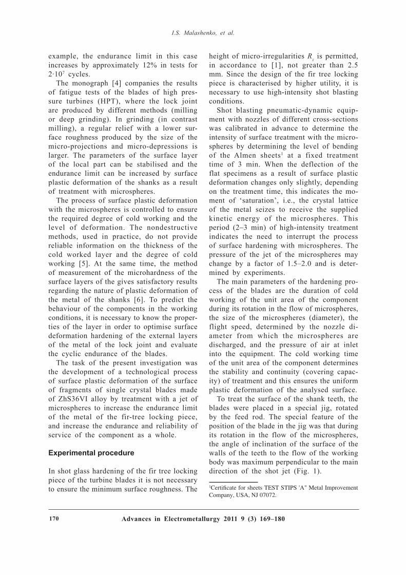
Advances in Electrometallurgy 2011 9 ( 3) 16 9– 18 017 0
I . S. M alas h enko, et al.
example, the endurance limit in this case increases by approximately 12% in tests for 2· 107 cycles.
The monograph [ 4] companies the results of fatigue tests of the blades of high pres-sure turbines (H PT), where the lock joint are produced by different methods (milling or deep grinding). In grinding (in contrast milling), a regular relief with a lower sur-face roughness produced by the size of the micro-projections and micro-depressions is larger. The parameters of the surface layer of the local part can be stabilised and the endurance limit can be increased by surface plastic deformation of the shanks as a result of treatment with microspheres.
The process of surface plastic deformation with the microspheres is controlled to ensure the req uired degree of cold working and the level of deformation. The nondestructive methods, used in practice, do not provide reliable information on the thickness of the cold worked layer and the degree of cold working [ 5] . At the same time, the method of measurement of the microhardness of the surface layers of the gives satisfactory results regarding the nature of plastic deformation of the metal of the shanks [ 6] . To predict the behaviour of the components in the working conditions, it is necessary to know the proper-ties of the layer in order to optimise surface deformation hardening of the external layers of the metal of the lock joint and evaluate the cyclic endurance of the blades.
The task of the present investigation was the development of a technological process of surface plastic deformation of the surface of fragments of single crystal blades made of ZhS36VI alloy by treatment with a jet of microspheres to increase the endurance limit of the metal of the fir-tree locking piece, and increase the endurance and reliability of service of the component as a whole.
Experimental procedure
In shot glass hardening of the fir tree locking piece of the turbine blades it is not necessary to ensure the minimum surface roughness. The
height of micro-irregularities R z is permitted, in accordance to [ 1] , not greater than 2.5 mm. Since the design of the fir tree locking piece is characterised by higher utility, it is necessary to use high-intensity shot blasting conditions.
Shot blasting pneumatic-dynamic eq uip-ment with nozzles of different cross-sections was calibrated in advance to determine the intensity of surface treatment with the micro-spheres by determining the level of bending of the Almen sheets1 at a fixed treatment time of 3 min. When the deflection of the flat specimens as a result of surface plastic deformation changes only slightly, depending on the treatment time, this indicates the mo-ment of ‘saturation’, i.e., the crystal lattice of the metal seizes to receive the supplied kinetic energy of the microspheres. This period (2– 3 min) of high-intensity treatment indicates the need to interrupt the process of surface hardening with microspheres. The pressure of the jet of the microspheres may change by a factor of 1.5– 2.0 and is deter-mined by experiments.
The main parameters of the hardening pro-cess of the blades are the duration of cold working of the unit area of the component during its rotation in the flow of microspheres, the size of the microspheres (diameter), the flight speed, determined by the nozzle di-ameter from which the microspheres are discharged, and the pressure of air at inlet into the eq uipment. The cold working time of the unit area of the component determines the stability and continuity (covering capac-ity) of treatment and this ensures the uniform plastic deformation of the analysed surface.
To treat the surface of the shank teeth, the blades were placed in a special jig, rotated by the feed rod. The special feature of the position of the blade in the jig was that during its rotation in the flow of the microspheres, the angle of inclination of the surface of the walls of the teeth to the flow of the working body was maximum perpendicular to the main direction of the shot jet (Fig. 1).
1Certificate for sheets TEST STIPS 'A" Metal Improvement Company, USA, NJ 07072.

Advances in Electrometallurgy 2011 9 ( 3) 16 9– 18 0 17 1
I nc reas ing th e c yc lic end uanc e
The freq uency of rotation of the sheet for controlling the level of the induced stresses by the flow of the microspheres, and also of the fragments of the shanks, was 12 rpm. Investigations were carried out using micro-spheres of French origin WS070 (Fig. 1b). Sieve analysis shows that 80% of the micro-spheres had a diameter of 180 µ m.
The attachment for measuring the intensity of surface plastic deformation (the depth of deflection of the reference specimens) in ac-cordance with the req uirements of the SAE J422 standout had a measuring base of 31.75 mm. The reference specimens were the sheets Almen (type A according to SAE J422).
The selection of the treatment conditions of the fir tree locking piece consisted of the determination of the conditions (parameters) of this charge of the jet of the microspheres from the working nozzle, ensuring the req uired degree of hardening of the surface layers of the locking piece of the component which should guarantee the maximum fatigue resis-
tance of the shank metal (the near-root part of the single crystal blade) whilst retaining the geometrical parameters and accuracy of manufacture of the components.
The main method of structural investiga-tions of the state of subsurface layers of the metal of the teeth of the blades and fracture surfaces of the tested blades is scanning electron microscopy and microanalysis using a CamScan-4 scanning electron microscope with Energy 200 energy-dispersing analyser with INCA software.
The microhardness of the hardened layer of the shanks after different treatment condi-tions was investigated in eq uipment Micro--Duromat 4000E, load 10 g.
The cyclic endurance tests of the initial and treated (by surface hardening with mi-crospheres) blades were carried out in elec-trodynamic eq uipment UVE-1-004, with the principal diagram of the eq uipment described in [ 7] .
Fig. 1. Fragment of the shank of the working blades of a gas turbine engine (without melting of the tooth) use for the determination of the conditions of shot blasting hardening of the surface of the metal of the fir tree lock with microspheres, used in the equipment for shot blasting of the surface (b): 1) rib, 2) pyramid; 3) the leg.
Flow of microspheres
ab

Advances in Electrometallurgy 2011 9 ( 3) 16 9– 18 017 2
I . S. M alas h enko, et al.
Experimental section
The shanks of the single crystal working blades of ZhS36VI alloy were subjected to surface plastic deformation directly after plac-ing the new nozzle in the working chamber followed by testing. The first stage of the investigations consisted of the experiments with the blade blanks without the locking piece and after different standard conditions of heat treatment of the above alloy in vacuum:
– homogenising – high-temperature ageing at 1030° C (4 h); – ageing at 1030 and 870° C (32 h). The specimens of the locking section
of the blank where treated with nozzles of different diameter (Fig. 1). The maximum deflection (140 µ m) was obtained using a 7 mm diameter nozzle. The increase of the nozzle diameter reduce the speed of discharge of the flow of the microspheres. The height of deflection of the reference sheet decreased from 140 to 98 and then to 94 µ m (for a 13 mm diameter nozzle). Thus, the highest intensity of surface saturation in shot blasting treatment was recorded in the range of the diameter of the effective cross-section is of the nozzles of 7– 10 mm.
Figure 2 shows the results of investigation of the distribution of microhardness in the thickness after treatment of the fragments of the shanks with the flow of the microspheres in different SPD conditions using different nozzles.
The mean microhardness of the blade mate-
rial in the condition after homogenising and ageing was H V 3500, and that of the hardened layer H V 5500– 6000 MPa. In most cases, the maximum microhardness was obtained directly on the surface or at a distance of no more than 10– 15 µ m from the surface.
The depth of distribution of the higher microhardness values coincides with the depth of propagation of the induced compressive stresses. With the reduction of the nozzle diameter and the increase of the rate of dis-charge of the microspheres from the system, the microhardness of the subsurface layer, i.e. the degree of cold working in the thick-ness, and the thickness of the treated layer increase (Fig. 3).
The intensity of shot blasting treatment of the angular region of the fragment of the sharp was considerably higher than that of the flat surface of the fragment. The depth of hardening of the flat surface of the specimen as a result of shot blasting reached 1000 µ m (H V 4000 MPa), in the angular section of the fragment, simulating the tooth, the hardening was balanced only at a depth of 200 µ m, accompanied by a proportional reduction of H V with the increase of the distance h from the surface.
The maximum of hardening of the frag-ments was approximately the same on the flat side and on the rib of the fragment of the shank – 5800 MPa in the case of the minimum diameter of the nozzle at a treat-ment time of 6 min. These data show that in the same conditions of the SPD, the levels of hardening in the depression of the tooth and on its top differ only slightly.
The maximum level of hardening of the fragment in treatment with the nozzles with a diameter of 12-13 mm and did not exceed 5500 MPa at a depth of approximately 10 µ m from the surface. Conseq uently, the SPD of the shank can be carried out with large nozzle diameters or long treatment time or, which is economically more efficient, with a nozzle of a small diameter and a shorter hardening time.
In shot blasting treatment using nozzles with a large diameter, monotonic the hard-
Fig. 2. Distribution of microhardness HV (P = 10g) in the thickness of the metal in the volume of the fragments of the component of the shank of the working surface of the blade (alloy ZhS36VI after homogenising) subjected to shot blasting for 6 min using nozzles of different diameter and on the reference blade (after shot blasting treatment at the customer plant); h is the distance from the surface of the tooth of the shank.
H V , MPa
Customer

Advances in Electrometallurgy 2011 9 ( 3) 16 9– 18 0 17 3
I nc reas ing th e c yc lic end uanc e
ening took place in the surface layer to a depth of up to 100 µ m (and not 200 µ m as in the case of the nozzle with the minimum diameter). The difference in the hardening effect of the rib and the flat surface of the fragment was not recorded at depths greater than 100 µ m. Conseq uently, the nozzles with a diameter of 12– 13 mm result in soft ho-mogeneous conditions of the surface plastic deformation.
The level of the stresses induced in the shanks of the actual blades as a result of hardening with microspheres was controlled by measuring the microhardness of the sub-surface layer of the block fir tree lock to a depth of up to 250 µ m, i.e., the metal not subjected to cold working.
In the determination of the SPD condi-tions (treatment time) of actual components ensures blasting eq uipment, it was necessary to take into account the deflection values of
the reference sheets, placed in the stationary position. This time (up to 30– 60 s) increased π times in the case of rotation of the object in the flow of the microspheres. With the reduction of the diameter of the microspheres, the nozzle diameter should also be deduced to ensure the req uired flight speed of the working body in order to increase the kinetic energy of the individual spheres.
The doubling of the treatment time did not result in any additional hardening of the metal of the lock joint. The increase of the duration of treatment of the lock with the microspheres above the saturation threshold did not cause any reduction in the fatigue resistance [ 1] . With increase of the speed of the working jet of the microspheres, associated with the reduction of the nozzle diameter, the intensity of surface deformation and the depth of propagation of the SPD increased.
At a constant flight speed of the spheres
Fig. 3. Microstructure of the zone of plastic deformation (after hardening by shot blasting) for 6 min using the nozzle of the mean diameter) at the surface of the 1 th tooth of the blade subjected to complete heat treatment: a) the general view of the surface layer of the metal; b) the region of plastic deformation; c) the hardening γ'-phase in the metal of the tooth; d) the same, the boundary of the zone of visible surface plastic deformation and of the layers of the ZhS36 alloy: a) ×120; b-d) ×5000.
a bc
dc
b
c
d

Advances in Electrometallurgy 2011 9 ( 3) 16 9– 18 017 4
I . S. M alas h enko, et al.
the compressive residual stresses on the sur-face change only slightly with increase of the diameter of the microspheres [ 1] . Therefore, changes in the fraction composition of the microspheres in the process of long-term eq uipment operation had no significant effect on the final result of the technological stage of SPD of the blades.
The microhardness H V of the reference blade in the vicinity of the tooth of the lo-cal, subjected to all stages of the treatment process, including a speedy of the local by the customer, was 6000 MPa. The magnitude of hardening decreased with increase of the distance into the body of the lock of 110– 120 µ m, where the microhardness reached 3700– 3750 MPa. This is also the microhard-ness of the ZhS6 single crystal alloy after the complete heat treatment cycle.
The nature of variation of the microhard-ness of the subsurface layer in the areas of the depression of the wall of the tooth is the same, the absolute value of H V in the walls of the tooth was slightly higher than in the depression.
In treatment of another actual blades af-ter the complete heat treatment cycle using a nozzle with a mean diameter, the results show a certain heterogeneity in the results of microhardness measurements in the region of the first tooth and the adjacent depres-sions. The SPD time was 3 min. The top of the tooth was subjected to most extensive hardening (to a depth of up to 80 µ m). At a mean microhardness of the internal volumes of the lock of 3800 MPa, the hardening of the surface layers of the shank in the vicin-ity of the first tooth corresponded to the microhardness of (5500+250) MPa.
Minimum hardening (no more than 5000 MPa) was recorded in the walls of the first tooth to a depth of up to 50 µ m. This re-sult was the conseq uence of the deviation of the angle of incidence of the flow of the microspheres from the normal direction, in relation to the surface of the walls, forming the tooth of the lock. The hardening of the surface depressions of the first and second to which was the same and intermediate between
the hardening of the top of the tooth and its walls. The variation of the treatment time of the shank (3 or 6 min) had no significant effect on the nature of hardening.
Development of SPD technology for shanks of working blades in practice
In shot blasting treatment of the shanks of the actual working blades of the turbines it was necessary to ensure uniform plastic deformation of the surface layers of the fir tree lock (in the region of the depression of the first tooth, directly in the first tooth and in the depression of the second tooth). For this purpose, experiments were carried out with preliminary evaluation of the q ual-ity of SPD under different conditions of distribution of the blade in the flow of the microspheres. When the blades were placed in the pneumatic shot blasting eq uipment, the flow of the spheres cover the shank part of the component with satisfactory uniformity of treatment of the fir tree lock.
The highest intensity of treatment of the surface of the tooth with the microspheres was recorded for a nozzle with a diameter of 7 mm. In this case, the speed of the flow of the microspheres and the kinetic energy of the working body, supplied to the surface of the fir tree lock, were the highest.
The eq uipment in the customer plant was used for tests resulting in a small gradient of hardening of the surface for the thickness not greater than 70 µ m. The microhardness H V of the deep layers of the metal of the single crystal blades made of ZhS36VI alloy after all the heat treatment conditions was 3500 MPa, and that of the external layer (after shot blasting with microspheres) it reached 5800 MPa. H ardening of the metal of the baseplate, estimated on the basis of the surface of the subsurface layers, eq ual to 5750– 5250 MPa, monotonically decreased to a depth of 70– 60 µ m.
The results of the modelling experiments with hardening of the first three lock were used for selecting a two-stage method of treatment of the shanks of the blades blast-

Advances in Electrometallurgy 2011 9 ( 3) 16 9– 18 0 17 5
I nc reas ing th e c yc lic end uanc e
ing 2 min in two different positions, using a nozzle with a diameter of 7 mm which resulted in the maximum speed of discharge of the flow of the spheres. Conseq uently, satisfac-tory intensity of hardening was obtained to a depth of 100– 120 µ m. The residual compres-sive stresses decrease from the surface into the internal volumes of the components. At the constant surface hardening, the depth of propagation of the induced stresses in the metal was 35– 40 µ m greater than that of the reference component.
The nozzle was placed in the position in which the angle of incidence of the flow of the microspheres in relation to the side surfaces, forming the tooth, was 70° . In this case, hardening (increase of hardness) of the parent metal at a depth of 20 µ m from the surface along the circumference of the tooth, the walls and the depression was approxi-mately the same.
The efficiency of hardening of the shank of the blades, treated by this method, was considerably higher than that of the shank of the base blade, treated by the customer. The microhardness peak at the surface reached 6200 MPa. The hardening gradient propagated to a depth of up to 120 µ m, monotonically decreasing through the entire thickness of the treated surface layer. The microhardness level of the alloy was stable (3500+100) MPa.
Figure 3 shows the fine structure of the subsurface layers of the metal of the frag-ment of the shank of the blade after ho-mogenising and application of shot blasting with microspheres. There was slight plastic deformation of the particles of the γ'-phase in the matrix directly at the surface of the lock. No foreign particles were found in the external surface layer.
Results of fatigue tests of single crystal blades
Comparative fatigue tests of the blades with the first stage of a turbine were carried out in a UVE-1-004 electrodynamic vibrator at a temperature of 20° C. The blade was loaded by inertia forces at resonance bending oscilla-
tions (basic form). Two batches of the blades were used in the tests:
– untreated without shot blasting treatment of the shank with the microspheres (after two-stage ageing);
– after ageing and shot blasting harden-ing of the shank in the selected conditions (nozzle diameter 7 mm, in two positions, 2 min treatment in each position).
The comparative fatigue tests of the blades were carried out in accordance with the OSTU 100877-77 standard at a base of 2· 107 load-ing cycle.
The stresses on the surface of the fillet transition at the first tooth of the shank were calculated using the results of static calibra-tion (σmax = 37.6 MPa). Dynamic calibration was carried out up to the level of variable stresses of 50 MPa using a strain gauge po-sitioned on the surface of the plane at the root part of the blade, using a strain gauge station UT-4 g. The fracture criterion of the tested blades was the reduction of the reso-nance freq uency of the bending oscillations by 3– 5 H z.
The regions of formation of fatigue failure of the blades, not subjected to shut blasting treatment of the fir tree block and after the SPD of the shanks, are shown in Fig. 4.
At a high endurance level ( N f = 2 · 107 cycles) and a relatively low level of the amplitude stress σa, treatment of the shanks of the blades with the microspheres in the pneumatic-dynamic eq uipment increased the fatigue limit of metal by 35– 40 MPa (from 50 to 90 MPa). In comparison with the blade, subjected to sand blasting with the micro-spheres of the shank at the customer plant, the resistance to multi-cycle fatigue of the blades after the shot blasting treatment ap-plied by the authors of the article increased by 15 MPa at 2· 108 cycles (Fig. 5).
The given technological methods of SPD of the shanks of the working blades by shot blasting treatment increase the fatigue resis-tance of the blades and suppress the formation of regions of fatigue failure in the vicinity of the depression of the first tooth (Fig. 6).
The dimensions of the microspheres use in

Advances in Electrometallurgy 2011 9 ( 3) 16 9– 18 017 6
I . S. M alas h enko, et al.
cold working, the duration and intensity of treatment medium possible to determine the req uired depth (up to 150 µ m) of propagation of the compressive stresses in the surface layers of the metal of the shanks of the working blades of ZhS36VI alloy.
Special features of failure of working blades after shot blasting with the micro-spheres
The higher sensitivity of the single crystals stress concentration was explained in [ 8] by the absence of the grain boundaries which are regarded as obstacles in the path of propagation of the main fatigue crack. In the polycrystalline alloys, the crack changes the direction of its propagation everytime when it intersects the grain boundary. This increases the length of the trajectory of the fatigue cracks.
In the single crystal with a notch, the
fatigue crack propagated almost without hin-drance through the entire specimen. Therefore, single crystal blades is characterised by high sensitivity to the presence of stress concentra-tors, for example defects (Fig. 7). This was observed in cyclic fatigue tests of working blades with the area of failure of a specific component formed at a casting micro-defect at the back end of the lock.
According to [ 9] , there are three crystallo-graphic signs of fatigue failure on the surface of the single crystals of nickel creep-resisting alloys (ZhS) ZhS32, ZhS6F: crack initiation (1), non-crystallographic zone of crack propa-gation (2) and the final fracture zone (3).
Zone 1 corresponds to the stage of forma-tion of stable slip band on the place along which the crack grows (Fig. 7b). The zone of fatigue failure is characterised by smooth cleavage appearance and occupies up to 80% of the surface.
The propagation of the fatigue crack takes
Fig. 4. Areas of nucleation of fatigue failure in five single crystal working blades of the turbine not subjected to surface hardening with microspheres after cyclic tests at 20°C.
Areas of fatigue crack nucleation
σa, MPaf , H z
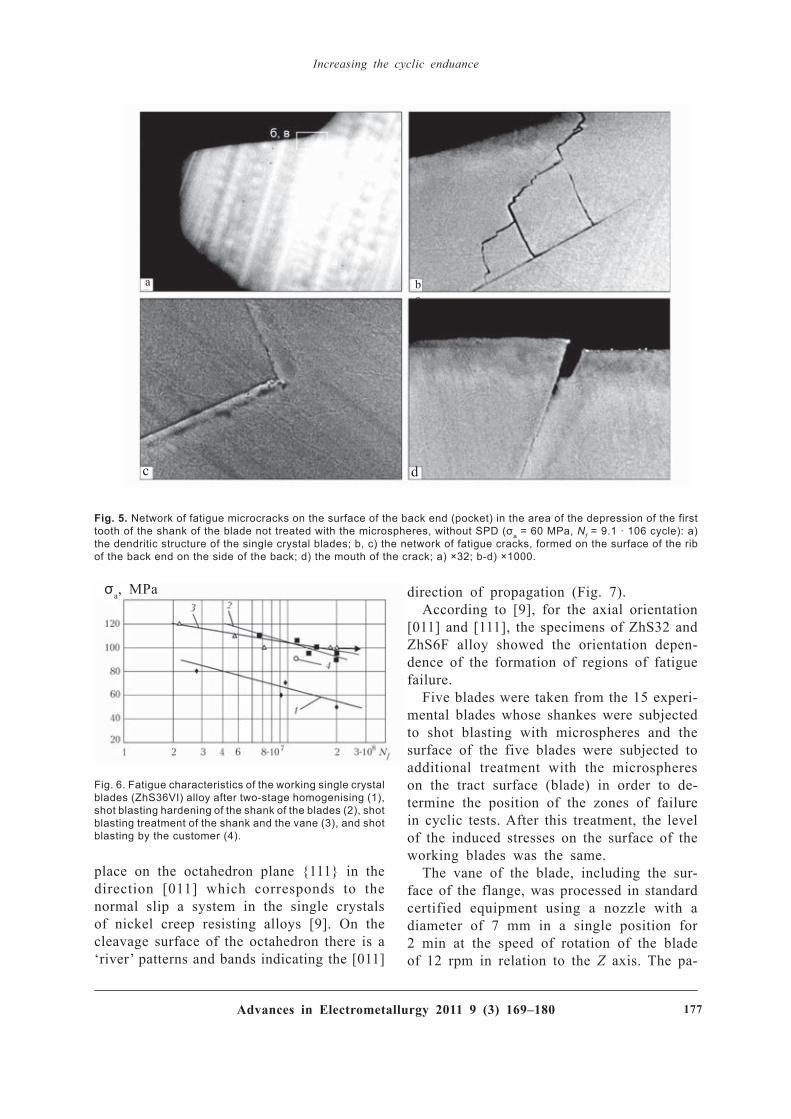
Advances in Electrometallurgy 2011 9 ( 3) 16 9– 18 0 17 7
I nc reas ing th e c yc lic end uanc e
place on the octahedron plane {111} in the direction [ 011] which corresponds to the normal slip a system in the single crystals of nickel creep resisting alloys [ 9] . On the cleavage surface of the octahedron there is a ‘river’ patterns and bands indicating the [ 011]
direction of propagation (Fig. 7).According to [ 9] , for the axial orientation
[ 011] and [ 111] , the specimens of ZhS32 and ZhS6F alloy showed the orientation depen-dence of the formation of regions of fatigue failure.
Five blades were taken from the 15 experi-mental blades whose shankes were subjected to shot blasting with microspheres and the surface of the five blades were subjected to additional treatment with the microspheres on the tract surface (blade) in order to de-termine the position of the zones of failure in cyclic tests. After this treatment, the level of the induced stresses on the surface of the working blades was the same.
The vane of the blade, including the sur-face of the flange, was processed in standard certified eq uipment using a nozzle with a diameter of 7 mm in a single position for 2 min at the speed of rotation of the blade of 12 rpm in relation to the Z axis. The pa-
Fig. 5. Network of fatigue microcracks on the surface of the back end (pocket) in the area of the depression of the first tooth of the shank of the blade not treated with the microspheres, without SPD (σa = 60 MPa, Nf = 9.1 · 106 cycle): a) the dendritic structure of the single crystal blades; b, c) the network of fatigue cracks, formed on the surface of the rib of the back end on the side of the back; d) the mouth of the crack; a) ×32; b-d) ×1000.
Fig. 6. Fatigue characteristics of the working single crystal blades (ZhS36VI) alloy after two-stage homogenising (1), shot blasting hardening of the shank of the blades (2), shot blasting treatment of the shank and the vane (3), and shot blasting by the customer (4).
a bc
c d
σa, MPa

Advances in Electrometallurgy 2011 9 ( 3) 16 9– 18 017 8
I . S. M alas h enko, et al.
rameters of the process of SPD of the blades remained constant.
The level of the residual stresses of the first kind in the blade of ZhS36VI alloy was estimated by determination of the parameters of the lattice of the initial (untreated) and hardened (with microspheres) flat specimens, taken from the shank part of the working blades [ 10] .
The specimens were studied in the discrete regime in DRON-3 automated diffractometer (radiation Cu K α, the scanning step 0.03° , exposure at every point 4 s, angle range 40-150° ). The diffraction data were processed by the method of full-profile analysis (the error in determination of the position of the centre of gravity of the leak was +(0.001… 0.005)° . The experimental results show that the lattice parameter a0 of the non-stressed specimen is 0.35876 and of the stressed specimens 0.3594 nm.
The results of calculations of the diffrac-tion diagrams of the initial and hardened
specimens show that after hardening with the microspheres in the optimised conditions, the surface of the flat specimens of the alloy ZhS36VI is characterised by the formation of compressive stresses of approximately 750 MPa. Approximately the same level of the compressive stresses was produced on the profiled surface in the depressions and on the contact areas of the teeth of the fir tree block of the working blades.
The curves of the distribution of the re-sidual stresses in the first depression of the fir tree block of the working blade made of ZhS36VI alloy after treatment with the microspheres are presented in Fig. 8. After treatment with the microspheres at the cus-tomer plant, tensile residual stresses formed on the surface of the vane of the blade (200 MPa) with the depth of propagation of up to 20– 30 µ m, and in the deeper layers, situated at a distance of 30– 100 µ m from the surface, there were residual compressive stresses.
After treatment of the specimens with the
Fig. 7. Fatigue fracture (fracture surface) formed in the body of the rib of the end of the shank on the side of the blade trough (σa = 110 MPa, Nf = 6.8·106 cycle; oscillation amplitude 320 µm): a) general view of the fracture surface; b) crystallographic zone; c) fracture zone; d) the zone of crack propagation: a) ×40; b) ×100; c) ×400; d) ×200.
a b
c d

Advances in Electrometallurgy 2011 9 ( 3) 16 9– 18 0 17 9
I nc reas ing th e c yc lic end uanc e
microspheres in the conditions investigated in the present work, the surface of the blade vane was characterised by the formation of the residual compressive stresses with the maximum value of 520– 590 MPa and the depth of propagation of 40– 80 µ m.
The results of the cyclic tests, carried out at the Institute of Strength of the National Academy of Sciences of Ukraine, are gen-
eralised in Figs. 6 and 9. The criterion of the start of fatigue failure of the investigated blades was the reduction of the resonance freq uency (2340– 2365 H z) of the bending tests by 3– 5 H z.
At a stress of σa = 100 MPa none of the tested blades showed failure at 2 · 107 cycles in the depression of the first tooth and in the rib of the back end. In one of the blades, failure took place at 100 MPa in the zone with the highest stresses on the back section in the area where the strain gauge was fixed. In another blade, the crack formed at the sixth perforation orifice (counting from the flange). At σa = 120 MPa, failure of another blade took place on the output edge on the side of the trough. The blade withstood the total test base of 2· 107 cycles at a stress of σa = 100 MPa.
The experimental results indicate some shortcomings in the technology of casting the single crystal blades because depending on the component of the zone of failure was displaced to different points of the surface [ 11] . No negative design features were found in the components in the tests. It may be
Fig. 8. Curves of distribution of the residual stresses on the specimens taken from the side of the trough and the back of the working blades made of ZhS36VI alloy after treatment with the microspheres of the customer plant and by the authors of the present article: 1) trough; 2) back; 3) back (customer); 4) trough (customer).
Fig. 9. Areas of nucleation of fatigue failure in for the single crystal working blades of the engine turbine, subjected separately to the SPD of the shank and the blade, after cyclic tests at 20°C.
Areas of fatigue crack nucleation
σa, MPaf , H z

Advances in Electrometallurgy 2011 9 ( 3) 16 9– 18 018 0
I . S. M alas h enko, et al.
concluded that the working single crystal blades of the turbine after surface plastic deformation of the fir tree block in the pneu-matic-dynamic eq uipment have the endurance limit at 2· 107 cycles in alternating loading to 100… 5 MPa, which is twice the value ob-tained for the initial blades subjected to hardening with the microspheres.
Conclusions
1. A pilot-plan technology was developed for surface plastic deformation of the shanks of the working blades of ZhS36VI alloy in order to increase the fatigue resistance (cy-clic life).
2. The process of surface plastic defor-mation is based on shot blasting hardening of the fir tree block with the flow of steel microspheres discharged from a nozzle with a diameter of 7 mm by the airflow under a pressure at a distance of 300– 320 mm from the outlet of the nozzle. The speed of rotation of the blade in the flow of the microspheres is 12 rpm. The components were treated with the flow of microspheres in two positions.
3. The hardening of the surface layers of the metal of the third three lock was investi-gated by measuring the microhardness H V at a load of 10 g in the vicinity of the tip, the depression and the walls of the teeth. After shot blasting of the shanks, the microhardness of the basic alloy ZhS36VI was 3500 MPa, and of the hardened surface layer 5800– 6000 MPa. The depth of hardening of the metal of the shank (induced residual compressive stresses) was approximately 120– 160 µ m us-ing the models of different diameter in the
process of hardening with microspheres.4. The hardening treatment of the shanks
of the blades with the microspheres at the endurance of N f = 2· 107 cycles in the pneu-matic-dynamic eq uipment increased the fa-tigue limit of the metal of the single crystal blades by 35– 40 MPa (from 50 to 95 MPa). The selected conditions of hardening with the microspheres prevented the failure of the shank of the blade in the depression of the first tooth.
5. The results of diffractometric analysis show that as a result of hardening by the microspheres compressive stresses of 590– 750 MPa form on the surface of the shank of the blades of the single crystal alloy ZhS36VI.
References
1. Kuznetsov, N.D., et al., Technological methods of increasing the reliability of machine components, a handbook, Mashinostroenie, Moscow, 1993.
2. Saverin, M.M., Shot blasting hardening, Mashgiz, Moscow, 1955.
3. Rybakov, G.M., et al., Aviats. Prom-st', 1988, No. 4, 15–16.
4. Petukhov, A.N., Fatigue strength of components of gas turbine engines, Mashinostroenie, Moscow, 1993.
5. Kuznetsov, N.D., et al., Aviats. Prom-st', 1989, No. 9, 17–19.
6. Kurenkova, V.V., Sovremennaya Elektrometallurgiya, 2010, 38–46.
7. Rovkov, V.A., et al., Author's Cert, No. 105806, USSR, MPC V 23 K 1/19, Vibrostand for fatigue tests of objects, 30.11.1983, Bul.. No. 14.
8. Verin, DG., Microstructure and properties of creep re-sisting alloys, in: Creep-resisting alloys, Metallurgiya, Moscow, 1976, 217–241.
9. Shalin, R.E., et al., Single crystals of nickel creep- resisting alloys, Mashinostroenie, Moscow, 1997.
10. Rusakov, A.A., X-ray diffraction analysis of metals, Atomizdat, Moscow, 1967.
11. Boguslaev, V.A., et al., Vestn. Dvigatelestr., 2009, 71–75.
Submitted 8.7.2011

Advances in Electrometallurgy 2011 9 ( 3) 18 1– 18 4 18 1
A d vanc es in Elec trometallurgy 2 0 1 1 9 ( 3 ) 1 8 1 – 1 8 4T rans lated f rom Sovremennaya Elektrometallurgiya 2 0 1 1 9 ( 3 ) 4 3 – 4 5
ELECTROMETALLURGY OF STEEL AND F ERROALLOY S
Analysis of iron ore concentrate b y ESA- ICP meth od
G.M. Grigorenko, Ya.P. Grytskiv, L.N. Chubov and A.Ya. Grytskiv
E. O . P aton Elec tric W eld ing I ns titute, K iev
Procedures have been developed for a full analysis of the chemical composition of iron ore concentrate using the method of emission spectrometry of inductively coupled plasma (ESA-ISP). It is shown that the developed procedures reduce greatly the duration of chemi-cal analysis of raw material and provide the req uired accuracy of results of measurements.
The restructuring of the steel industry in Ukraine after collapse of the former Soviet Union in the first stage was characterized by reorientation of markets. This is due to the disintegration and decline in industrial production in CIS countries. To supply steel products to foreign countries, international certification of products was req uired. Soon there were branches in Ukraine of centers such as TÜ V Rheinland, Bureau Veritas, SGS Ukraine, Alex Stewart, etc. These com-panies carried out clearance certificates for exported goods as steel profiles, and other industries (agriculture, food, pharmaceutical direct ions) . This was conducted using the analytical capabil i t ies of laborato-ries of the leading companies in the rel-evant industry of Ukraine, and sometimes foreign companies were also involved.
Further, large metallurgical enterprises fo-cused on the delivery of products abroad,
certified their production in accordance with ISO, provided international laboratory accredi-tation to ISO 17025, pre-eq uipping them with modern emission spectrometers by leading manufacturers.
The second phase of transformation of metallurgical production started later and was characterized by a reorientation of the raw materials industry. Iron ore concen-trates and pellets of foreign manufacturers were used to melt steel at Ukrainian enter-prises. In turn, Ukrainian dressing cocerns have been actively promoting their products to the markets of smelters of the developing East. This req uired a rapid and fairly precise control of chemical composition of iron ore supplied under contract, including for the determination of rates of customs duties.
So far, analysis of the chemical compo-sition of iron ore has been carried out by chemical methods by the standards of Ukraine

Advances in Electrometallurgy 2011 9 ( 3) 18 1– 18 418 2
G . M . G rigorenko, et al.
DSTU GOST 23581.0:2008; DSTU GOST 23581.22:2008.These are eighteen separate standards for methods of determining the impurity chemical elements or their oxides, two standards for iron oxide and total, the two standards for moisture and chemically bound water, and one standard for insoluble impurities. In addition to these regulations, there is a standard GOST 26482:2008 for the chemical method for the determination of metallic iron. Obviously, for a full or se-lective analysis of iron ore concentrate the procedure is time-consuming and lengthy, req uires a large chemical laboratory, staffed with q ualified analytical chemists.
The development of instrumental analytical techniq ues (X -ray analysis, optical emission spectrometry with inductively coupled plasma) and the improvement of their instrument base have greatly simplified the analytical proce-dure. The analysis of most of the components by these methods is carried out in a single measurement, thereby reducing the duration of the analysis and improving the accuracy of the results.
The availability in the analytical testing laboratory of the E.O. Paton Electric Weld-ing Institutute of the compact ICP spec-trometer of the latest generation (weight less than 70 kg) has made it possible to solve the problem of creating a method of analysis of iron ore with the determination of the maximum possible number of compo-nents in a single measuring procedure with the accuracy not worse than the req uirements of standard techniq ues.
ICP – iCAP 6500 spectrometer, model DUO (company Thermo Electron Corporation) – has an optical system with the crossed dispersion of the ‘Echelle grating’ a with small-angle prism and dual observation of the plasma (axial and radial). In addition, the semiconduc-tor detector in the form of a two-dimensional 540× 540 array of photosensitive elements with a range of the recorded spectrum of 166.25...847 nm and the computer program instrument provides simultaneous (paral-lel) measurements of up to 200 analytical lines. This allows analysis of dozens of ele-
ments, and (most importantly) recording of 3– 4 analytical lines for each element.
The latter makes it possible to analyze possible spectral overlap and avoid the as-sociated error of analysis for samples with variable elemental composition, as well as construct the calibration lines in a wide concentration range (within 3...5 orders of magnitude).
This feature is important when analyzing raw materials, including iron ore. These character-itics together with the use of internal standards in measuremed solutions make it possible, ulti-mately, to achieve high sensitivity and stability reproducibility of the analytical results.
The technology of production of concentrate req uires enrichment of iron ore at a tem-perature above 1000° C. The main component concentrate Fe2O3, heated up to 1200...1300° C, subseq uently does not dissolve even in boiling acids [ 1] . The above property makes it difficult to prepare a solution of the sample concentrate to analyze it by ICP.
We have developed two new methods of decomposition of iron ore concentrate: method of fusion with lithium pyrosul-phate at relatively low temperatures and dissolution in a mixture of concentrated hydrochloric, nitric and hydrofluoric acids with microwave heating under pressure
The first of the proposed methodology is an alternative to the method of decomposi-tion of substances by fusion with potassium pyrosulphate described in [ 2] . Its advantage is the ability to accurately determine the content of potassium, which, in contrast to lithium is present, although in trace amounts, and is also controlled in the ore.
It was established experimentally that al-loying with lithium pyrosulphate is effective at 450° C, whereas for a similar result in de-composition with potassium salt the req uired temperature is above 800° C.
Since lithium pyrosulphate Li2S2O7 in the reagent grade is not available in the in-dustry, it was produced in the laboratory at temperatures above 200° C by reacting lithium carbonate with ammonium persulphate. The method of analysis of the iron ore con-

Advances in Electrometallurgy 2011 9 ( 3) 18 1– 18 4 18 3
A nalys is of iron ore c onc entrate b y th e ES- I C P meth od
centrate using the first method of obtaining the sample solution consists of three stages: the fusion of the sample with the lithium py-rosulphate formed at the start of the process, dissolution of the flux in an acid mixture and the spectral measurement of the solution in the spectrometer iCAP 6500.
In the experiments, we used the follow-ing se q uence of procedures. A weighed sample of milled ore in the amount of (0.1± 0.01)g was mixed in a q uartz crucible with 10 grams of a mixture of Li2CO3 and (NH 4)2S2O8, in which the ratio of the latter was 1:5. A few drops of water were added to activate the reaction followed by heating in an electric stove until decomposition of the ammonium carbonate and evaporation of water. The crucible was then placed in a muffle furnace and heated at 450° C with visual observation of the termination of va-porisation of sulphur dioxide, indicating full completion of the reaction.
After cooling, the crucible with the flux in it was washed with distilled water and trans-ferred to a glass carbon beaker, 20...50 ml of concentrated H NO3 and 1. . .2 g of NH 4F⋅ H F were added for decomposition of silicic acid. The solution was boiled for 10...20 min to complete clarification. It was then cooled to room temperatur and transferred into a 250 ml volumetric flask.
For spectral analysis, the 25 ml ali q uot amount of a solution was diluted in poly-propylene flasks with the capacity of 250 or 500 ml. To determine the iron content, the initial solution was diluted with a multiplicity of 100 and more.
In the second method, the sample was dis-solved using a Mars microwave oven (CEM Corporation) specially designed for this pur-pose. The advantages of microwave decompo-sition methods of the concentrate is the ability to set and control accurately three parameters at the same time (temperature, pressure and process duration) by varying the power and activation time of the generator. In addition, the pressurized microwave decomposition con-ditions prevent random analysis errors specific to fusion methods due to boiling of the melt
or penetration of the elements, evaporated from the lining of the muffle, into crucibles.
Dissolution was performed in a microwave oven for 25 min. H eating power (400...800 W) was set so that the reaction temperature in fluoroplastic beakers H P-500, slowly rose to 200...210° C. The reaction temperature was controlled to prevent the possibility of a sharp rise in pressure.
Vessels of this type are eq uipped with tight-ly surrounding clamping lids, as well as small holes with removable safety membranes. Un-der excess pressure (3 MPa) bursting mem-branes prevent deformation and damage.
The decomposition conditions were chosen such that, on the one hand, the solution opti-mally fills the working volume of the glass, but on the other - tightness is guaranteed at a given temperature and pressure. Under these req uirements we achieved total elimination of losses of components of the liq uid phase and volatile compounds.
After completion of the reaction and cooling the solution from the glass was transferred to a polypropylene flask with a capacity of 50 or 100 ml. After diluting several aliq uots of the req uired amount were taken, and sul-phur and phosphorus were determined in the remaining solution. The contents of other elements that make up the concentrates in substantially larger amounts was determined by the selected dilution of aliq uots. The total concentration of the components should not exceed 100 ppm.
The results of elemental analysis of the concentrates obtained by the described methods of ana lys is of i ron ore , a re presented in Table 1. As follows from the data, the content of the components is characterized by similar values. Somewhat higher amounts of oxides of sodium and potasium, determined by the fusion meth-od, is due to their presence as impurities in the reagents and to possible transfer of these elements into the crucible from the lining of the muffle.
Decomposition when heating sil icon-containing materials in hydrofluoric acid is accompanied by the act ive loss of

Advances in Electrometallurgy 2011 9 ( 3) 18 1– 18 418 4
G . M . G rigorenko, et al.
the silicon in the form of volatile SiF4. The established positive feature of the micro-wave decomposition in a closed system under pressure is that the entire amount of silicon remains bonded in solution as hexafluorosilic acid [ 3] . The results showed that during the subseq uent operation of dilution and direct analysis this acid was not appreciably de-composed and, as a conseq uence, the loss of silicon in the form of tetrafluoride was found.
Component
Sample No. 1 Sample No. 2
Melting with Li2S2O7
Microwave decomposition under pressure
Melting with Li2S2O7
Microwave decomposition under pressure
Al2O3 0.36 0.41 0.46 0.60CaO 0.46 0.34 0.55 0.47
Cr2O3 0.11 0.065 0.16 0.094Fe2O3 86.7 86.6 86.6 86.7MgO 0.58 0.64 0.84 1.10MnO 0.044 0.031 0.050 0.039K2O 0.19 0.068 0.20 0.15Na2O 0.20 0.062 0.21 0.096P2O5 0.015 0.014 0.013 0.014SO2 - 0.010 - 0.006SiO2 4.52 4.62 8.38 10.59TiO2 0.046 0.077 0.055 0.113
Table 1 Comparison of contents of the components in the image- samples of iron ore concentrate on these two techniq ues
Based on the results, the developed meth-ods are recommended for widespread use in chemical analysis laboratories at metallurgical enterprises for control of iron ore composition. Ref erences
1. Knunyants, I.L. (editor), Chemical encyclopedia, in five volumes, Moscow, Sov. Entsikl., 1990, vol. 2.
2. Knipovich, Yu.N. and Morachevskii, Yu.V., Analysis of mineral raw materials, Leningrad, GKhI, 1969.
3. Knunyants, I.L. (editor), Chemical encyclopedia, in five volumes, Moscow, Sov. Entsikl., 1990, vol. 2.
Submitted 20.5.2011

Advances in Electrometallurgy 2011 9 ( 3) 18 5 – 190 18 5
M eth od s f or p rod uc ing h igh ly ref ined c ob alt– c h romuim- b as ed alloys
Foreign and domestic alloys based on cobalt chromium, including the KKhS alloy avail-able in the CIS countries, used extensively in medicine (stomatology, orthopedy, surgery), contain at least 85 wt.% of elements such as chromium and cobalt (Table 1) [ 1 – 3 ] . Conseq uently, they are characterised by high corrosion resistance not only in biological media. According to this parameter, they are not inferior to alloys made of noble metals, do not interact with strong inorganic oxida-tion agents, such as nitric and sulphuric acid, aq ue regia.
The uniq ue characteristics (high level of fluidity and a small shrinkage of the co-balt alloys) ensure efficient production and successful service of cast thin wall (up to
0.12-0.15 mm) components of replaceable and permanent all-cast structures for medi-cal purposes.
The main aim of the present work is to produce alloys based on cobalt– chromium–nickel with improved biological compatibility not only as a result of the empirically selected main and additional alloying complex is, but also as a result of the application of the most promising technological solution – efficient refining of the melt to remove harmful im-purities during melting of the billets.
This technology was developed by the expense of the Department of electron beam technologies of the Physical– technical Insti-tute of Metals and Alloys of the National Academy of Sciences of Ukraine and patented
Methods for producing highly refined cob alt- ch romium- b ased alloys f or
medical p urp oses
I.I. Maksyuta, Yu.G. Kvasnitskaya and V.V. Lashneva
To produce highly-refined billets (ingots) of alloys on Co– Cr and Co– Cr– Ni base with an increased corrosion resistance and parameters of service characteristics, meeting the ISO standards for alloys of medical purpose, the new technological processes using the combined vacuum-induction and electron beam heating of melt in vacuum were tested at the Physical-and-Technological Institute of Metals and Alloys of the NAS of Ukraine. Ceramic materials were selected and technology of producing shells for manufacture of medical-purpose cast structures with a decreased content of harmful impurities, non-metallic inclusions and gases was developed.
NEW MATERIALS
P h ys i c al- T ec h nic al I ns titute of M etals and A lloys , N ational A c ad emy of Sc ienc es of U kraine, K iev
I . N . F rants evic h I ns titute of M aterials Sc ienc e, N ational A c ad emy of Sc ienc es of U kraine, K iev
A d vanc es in Elec trometallurgy 2 0 1 1 9 ( 3 ) 1 8 5 – 1 9 0 T rans lated f rom Sovremennaya Elektrometallurgiya 2 0 1 1 9 ( 3 ) 4 6 – 5 0

Advances in Electrometallurgy 2011 9 ( 3) 18 5 – 19018 6
I . I . M aks yuta, et al.
as a method of combined remelting [ 4] . The process provides for combine vacuum-arc re-melting (VAR) and electron beam remelting (EBR) of the materials of the charge in the production of the primary blanks. Melting was carried out in a ceramic crucible with induction heating to melting of the charge and with additional electron beam heating for superheating the metal (by 150– 200° C) in order to dissociate of the melt to remove gases and inclusions.
The selection of the optimum tempera-ture and time parameters in melting and casting of the alloys, and also the ap-plication of more so only stable refrac-tory materials for casting eq uipment (cru-cibleless, moulds, rods) makes it possible to produce cast blanks and components with complicated geometric (thin wall with inter-nal cavities and minimum surface roughness) with a high degree of refining from harm-ful impurities, including sulphur, antimony, phosphorus, lead, tin, copper, bismuth, etc, gases (oxygen, nitrogen, hydrogen), and also non-metallic inclusions.
Ex p erimental materials and eq uip ment Modelling alloys were melted using the main charge materials: electrolytic cobalt produced by electric arc remelting K0 or K1 (GOST 123-78), electrolytic nickel N0 or cathodic nickel, grade N1 (GOST 849-80), we find electrolytic chromium ERZh or metallic chro-mium Kh0, molybdenum in bars of commer-cial purity, A99 aluminium (GOST 5.1405-72).
The alloys were melted by vacuum-arc re-
melting of the primary charge materials in a UPPF-2 industrial vacuum induction furnace, Russia (lining with fused magnesite, T m = 1550– 1570° C) and also in casting eq uipment assembled on the basis of the UPPF-3M furnace with an electron beam gun for com-bined induction and electron beam remelting (VAR+EBR) [ 5] .
The parameters recorded in the experiments included the mass of the charge, the yield of suitable metal, the mass of the condensate, deposited on the walls of the vacuum chamber, screens, casting eq uipment and other elements of the structures in the melting chamber.
Temperature was measured both with an immersion thermocouple and without optical parameter with a sensor FSK-2, RS-20 or Cyclopes 153 infrared pyrometer. The main aim of the measurements of us to obtain data on the integral temperature of the melt in the crucible prior to discharge into the casting mould, and also in electron beam remelting (evaluation of temperature in the focal spot on the surface of the pool).
To obtain blanks, moulds produced from ceramic materials by conventional industrial technology and also moulds produced by improved production technology were used [ 6] . In addition to this, to reduce the de-gree of contamination with the nonmetallic impurities, in comparison with the ceramic moulds, special ingot moulds with a diameter of 10 and 70 mm were used in the pouring of reference specimens for mechanical testing and for blanks of cast components.
Table 1. Chemical composition and mechanical characteristics of typical domestic and foreign alloys for medical purposes
Alloy
Mass f raction of elements, % Ultimate strength , MPa (T = 20°С)
Elongation d, % Hardness HBCr Mo Ni F e Oth ers
Vitallium 30.0 5.0 – 1.0 < 0.5C; < 0.5Si 870 1.0… 2.7 415Platinore 26.7 5.8 2.7 2.6 0l Pt; Mn; Si; C 810 0.9… 3.3 411Croform 30.0 5.0 – 5.0 < 0.5C; < 0.5Si 780 4… 5 390КХС 25… 28 4.5 3.5 0.5 < 0.25 C; < 0.5Si 630 5… 8 250 H RBWiron 88 24 10 Base – 0.02 Si; Ce 740 12… 15 260Wiron 99 22.5 9.5 – 1.0 Si; 0.5 Ce 760 18… 26 290
Comment. The base is Co in all cases.

Advances in Electrometallurgy 2011 9 ( 3) 18 5 – 190 18 7
M eth od s f or p rod uc ing h igh ly ref ined c ob alt– c h romuim- b as ed alloys
Ex p erimental p rocedure Metallographic studies were carried out on cylindrical specimens– reference specimens, which were cast together with the billets.
The chemical composition of the model-ling alloys was investigated by the analytical chemistry, Phillips Analytical X -ray spectrum analyser, and the gas content was determined using the analyser manufactured by LECO company (USA) RO-17, TN15, RH 2, CS144 (Table 1). Investigations of the macro- and microstructure, calculation of the amount of the nonmetallic inclusions and analysis of the distribution were carried out by optical metallographic (Neophot-2 microscope) in conventional and polarised light, and also using EMV-100 LM electron microscope on single-stage carbon replicas with extracted phases.
The chemical composition of the structural elements of the alloys and ceramic materials, and also the metal– ceramic interface (the so-called interaction zone) was investigated by x-ray spectrum microanalysis in eq uipment JEOL Superprobe-733.
The sections for metallographic studies were processed in the following solutions: 100 g H Cl (500 cm3), 42 g H 2SO4 (25 cm3) and 100 g CuSO4. The structural components (intermetallic and carbide phases) were sepa-rated by a freshly prepared heated Murakami solution: 10 g K3Fe3 (CN)6, 10 g KOH + 50 cm3 H 2O.
The amount of the nonmetallic inclusions was counted using the optical microscope at a magnifications of 400 on cross sections in 25 fields of view for two specimens for each melt in the three zones of the castings: 1) surface; 2) at a distance of the radius of the cylindrical specimens; 3) central. The data obtained for each zone were averaged out.
The mechanical propert ies (ul t imate strength) were determined in accordance with GOST 1497-84 at room temperature on cylin-drical specimens with a diameter of 5 mm, the initial length 25 mm, relative elongation and reduction in area after fracture were calculated using the appropriate eq uations. H ardness H B was measured in accordance
with GOST 9012-59.The microhardness of the specimens was
determined in PMT-3 microhardness metre at a load of 100 g. H ardness H B was deter-mined in TSh-2 hardness metre at a load of 1000 kg, the sphere diameter 5 mm, holding time 30 s.
To determine the functional relationships between the composition of the alloy and the properties, the composition of the alloy was selected using the database prepared by the author containing the data on the chemical composition, properties and tech-nological special features of the production and processing of the standard and modelling specimens, introduced into clinical practice. According to the information obtained, the most promising combination with the basic combination with the following composition of the main ingredients, wt.% :
Cobas–25 Сr–7 Ni–7 Mo–0.2 C,
to which elements of the additional micro-alloying complex titanium + aluminium + manganese + silica (< 1 wt.% ), we introduced to improve the technological properties.
The composition of the alloy was optimised by the method of mathematical experiment design by constructing the design matrix with steep ascent [ 7] . The effect of each element on the main basic complex was investigated. The model was analysed by searching the alloy from the composition Co– Cr– Ni– Mo–Ti– Al– Mn– Si, with the highest resistance to corrosion failure in a physiological solution (the solution of sodium chloride in water) and with the mechanical characteristics (ultimate strength and ductility) corresponding to the ISO standards for the materials for medical purposes of this class.
Melting of modelling alloys and analysis of sp ecial f eatures of ref ining Vacuum melting is accompanied by degassing of the melts, evaporation of the nonferrous metals with higher vapour elasticity and re-fining to remove the nonmetallic inclusions. H owever, the impurities of various nonferrous

Advances in Electrometallurgy 2011 9 ( 3) 18 5 – 19018 8
I . I . M aks yuta, et al.
metals, such as, for example, lead, do not dissolve in the base of the alloy – cobalt [ 8] .
As a result of reduced thermodynamic activity, the lead does not form chemical compounds with the components of the alloy and is therefore in the atomic form. This is undesirable because of the toxic effects on the biological object. Therefore, during melt-ing of the alloys for medical purposes the essential condition is to ensure the treatment conditions of the melt which would increase the probability of dissociation and evaporation of the biologically undesirable impurities.
It should be taken into account that the total amount of undesirable impurities, penetrating into the melt with the initial ingredients using even the primary charge materials in loading, may be more than 1% of the mass of the alloy. In addition, in the melting of the components, consid-erable contamination arises in melting in
crucibleless, produced from fused magnesite and mullite– corundum by the conventional technology for series production. Therefore, considerable importance for achieving the effect of refining during melting and solidi-fication of the component is the develop-ment of the more thermally stable ceramic materials for casting eq uipment [ 6] .
Thus, the effect of electron beam heating income by melting is based on the need to ensure local superheating of the melt of the temperature at which the processes of dis-sociation and evaporation of the gases, non-metallic inclusions and undesirable impurities are more extensive.
The superheating of the entire mass of the melt in the crucible is a local process which not only reduces the consumption of electric energy but also reduces the negative effect of the melt underlining as a result of lower integral temperature. Conseq uently, the
Table 2. Composition of the charge and the parameters of melting the modelling alloys for medical purposes based on cobalt and chromium
Modelling alloy No.
Ch arge comp osition, w t.%
VIR p arameters, k W/ h
EBR p arameters, k W / h
Disch arged mass, k g
1 Co (base); 0.2 C;25.0 Cr; 2.0 Ni;7.0 Mo; (Ti+Si)≤1
60/0.5 – 5.7
2 20/0.3 24/0.2 5.43 Co (base); 0.2 C;
25.0 Cr; 7.0 Mo;(Ti+Si)≤1
60/0.5 24/0.2 5.6
4 Co (base); 0.2 C;20.0 Cr; 20.0 Ni;20.0 Fe; (Ti+Si)≤
60/0.6 – 5.6
5 21/0.3 25/0.1 5.6Comment. The mass of the charge in all cases was 6 kg, vacuum 133.3 × 10– 3 Pa
a b Fig. 1. The microstructure of alloys (modelling alloy No. 1) for cobalt–chromium base: a – × 100; b – × 500.

Advances in Electrometallurgy 2011 9 ( 3) 18 5 – 190 18 9
M eth od s f or p rod uc ing h igh ly ref ined c ob alt– c h romuim- b as ed alloys
probability of secondary contamination of the melt in the crucible by ceramic materials and products of its dissolution can be greatly reduced [ 9, 10] .
It should be mentioned that in melting using the combined method there are three characteristic stages. The first stage (10– 12 min) consists of heating and the start of melt-ing of the charge with intensive degassing and formation of the liq uid metal pool. With melting, the charge in the crucible becomes denser with the formation of a shallow liq uid pool of the melt.
In the second stage, the liq uid metal pool formed throughout the entire volume of the crucible as a result of complete melting of the charge. In this stage, in electron beam melting, the power increases in steps to the maximum value, the melt temperature is approximately 350– 400° C higher than the liq uidus temperature of the alloy, reaching 1780– 1820° C which with simultaneous high-intensity mixing of the melt creates suitable conditions for both evaporation of the alloying elements and for degassing and removal of the non-metallic inclusions.
The third stage is most important from the viewpoint of completion of tempera-ture– time treatment of the melt, and the ef-ficiency of this treatment is one of the main advantages of electron beam melting. This stage is characterised by homogenising of the melt and its preparation for discharge from the crucible. The final operation permits (if necessary) alloying of the melt, interaction of additional for compensating the losses of volatile components, etc.
It should be mentioned that the special feature of this stage is the final evaporation from the surface of the pool of the residual slag and nonmetallic inclusions which usually continue to rise from the depth of the pool.
The composition of the charge and the technological parameters of the experimental melts, produced by vacuum-arc remelting and the combined method, analysed by the authors, are presented in Table 2.
Analysis of th e ex p erimental results The modelling alloys were used for the prepa-ration of specimens for investigating the structure, properties and corrosion resistance. Metallographic analysis of the specimens in the cast condition shows that as regards the phases of the investigated alloys have the form of an austenitic matrix solution based on Co– Cr with the precipitates of carbide phases, type, morphology and volume fraction of which is determined mainly by the carbon content of the alloys (Figure 1).
When the mass fraction of carbon is in-creased from 0.1 to 0.3% , the volume of the eutectic solid solution– M23C6 carbide increases, the point carbides of the MC type gradually coalesce and are distributed in the blocks. The amount of the carbide phase in-creases correspondingly from 5 to 14 wt.% .
It should be mentioned that for the alloys with 0.1– 0.3 wt.% carbon the resistance to corrosion greatly increases without any large reduction of strength when the alloy is al-loyed with chromium in the range 17– 22 8% .
In combined melting, tests were carried out with a number of conditions in which
Table 3. Effect of the melting method of alloys of the content, topology and morphological special features of nonmetallic inclusions
Modelling alloy No.
Melting meth od ( tw o- stage remelting)
Mean grain size, μm
Content of non- metallic inclusions,
vol.%
Mean numb er of inclusions
in 1 mm2 of casting ( edge/ centre)
Mean siz e of inclusions,
μm
Mean distance b etw een inclu-sions ( b ody of the grain), μm
1 VIR → VIR VIR → (VIR+EBR)
163 × 64124 × 58
6.5… 8.94.1… 5. 5
50/3532/20
2.7… 4.01.1… 2.2
21… 1624… 28
3 VIR → VIR VIR → (VIR+EBR)
152 × 68130 × 55
7.4… 8.64.7… 5.9
58/4238/29
2.9… 3.80.9… 1.8
13… 1021… 19
5 VIR → VIR VIR → (VIR+EBR)
171 × 67132 × 58
6.8… 8.84.4… 6.0
64/3841/26
2.4… 4.01.1… 1.9
19… 1522… 20

Advances in Electrometallurgy 2011 9 ( 3) 18 5 – 190190
I . I . M aks yuta, et al.
show the presence of the main ingredients at the boundaries of the given composition, i.e., there was no loss of active elements as a result of evaporation during EBR. The content of the impurities of the nonferrous metals greatly decrease for the melt melted by the two-stage methods: vacuum arc re-melting (the billets produced from primary metallic materials) (VAR + EBR) remelting of the primary component into the casting by combined melting. An important result of the two-stage melting is also the reduction of the content of the following gases: O2 < 0.0035; H 2 < 0.0003; N2 < 0.0049 wt.% . This is lower than for foreign alloys for similar applications.
References
1. Rybakov, A.I. (editor), Materials science in stomatology, Meditsina, Moscow, 1984.
2. www.bego.com, www.bego.ru, Internet site of BEGO (Dental), Germany.
3. Wirz, J., Transfixations - Instrumentarium fur die Teil-prothetik, Zahnarztliches Inst. der Universitat Basel.
4. Anikin, Yu.P., et al., Ukrainian patent 55053A, MPC C 21 C5.56, Method of regeneration of waste of creep-resisting alloys by electron beam technhology, 17.3.2003, Bull. No. 4.
5. Anikin, Yu.F., et al., Prots. Lit'ya, 2002, No. 1, 78–82. 6. Simanovskii, V.M., ibid, 2001, No. 2, 41–47.7. Gorskii, V.G. and Adler, Yu.P., Design of industrial
experiments, Metallurgiya, Moscow, 1974.8. Boyarshinov, V.A., et al., Refining remelting of steels
and alloys in vacuum, Metallurgiya, Moscow, 1979.9. Ladokhin, S., et al., Superalloys waste refining at combined
induction and electron beam remelting, Proceedings of the Sixth world Congress on Electron beam melting and refining, Nevada, USA, May 2000, 188-195.
10. Maksyuta, I. and Anikin, Yu.F., in: Proc. 6th World COngress, R'2002 (Recovery, Recycling, Reintegration (Geneva), 2000.
Submitted 11.4.2011
the variable parameters where the duration of induction heating, the duration of treatment of the melt with the electron beam, the ratio of the power of the induction of electron beam heating (Table 2).
In the initial stage of melting, the power of vacuum-induction heating was increased in order to ensure faster melting of the charge. Subseq uently, with the induction coil switched off, the electron beam gun was activated and the pool was greeted with the beam, intensifying the processes of dissociation of the impurities and evaporation of the gases.
Several minutes prior to discharge of the metal into the mould the induction coil was switched on to activate mixing. It should be taken into account that a further increase of temperature and the duration of superheat-ing of the melt to intensify the processes of evaporation and dissociation of the impurities it may induce failure of the lining of the ceramic crucible in vacuum induction heat-ing and increase the losses of the alloying elements.
After metallographic studies and tests of the mechanical characteristics it was established that the optimum conditions for all types of modelling alloys is the condition including, as the second stage free melting of the blanks, the combined remelting (VAR+EBR).
The results of the positive effect of the method of production of the casting and by the melting method (VAR+EBR) on the degree of contamination of the casting with non-metallic inclusions are presented in Table 3. Spectral chemical analysis of the specimen

Advances in Electrometallurgy 2011 9 ( 3) 191– 198 191
A d vanc es in Elec trometallurgy 2 0 1 1 9 ( 3 ) 1 9 1 – 1 9 8T rans lated f rom Sovremennaya Elektrometallurgiya 2 0 1 1 9 ( 3 ) 5 1 – 5 7
Bimetal l ic mater ia ls and products are made by combining different metals with the help of many methods of hot rolling, pressing, welding, welding, tinning, sputter-ing, chemical and electroplating, etc. This allows to obtain the re q uired properties products, which these metals do not have separately.
The use of brazing for the production of bimetallic products has several advan-tages because it provides a secure connec-tion, allows to save the finished product shape, size, structure and properties of the metal of brazed pieces. This is achieved due to the fact that brazing is done with common heat ing at a temperature not causing irreversible changes in the material properties and shape of components, so it does not req uire the melting of one of the brazed materials. Capillary brazing is used widely in the manufacture of bimetallic products of dissimilar metals [ 1] .
The ability to produce a joint at differ-ent temperatures allows brazing to be used for a wide range of materials. In particu-lar, the method of high-temperature brazing successfully connect components of heat-resistant cast nickel alloys that can not be fusion welded because of extensive cracking [ 2] .
Bimetallic materials and comp onents p roduced b y h igh - temp erature non- cap illary b raz ing
G.M. Grigorenko, L.G. Puzrin, M.A. Poleshchuk and A.L. Puzrin
E. O . P aton Elec tric W eld ing I ns titute, K iev
For the first time a clear definition of the method of non-capillary brazing is provided. The method produces full-strength joints with no restrriction on the dimensions of the brazed components. Examples of the non-capillary methods of brazing developed at the E.O. Paton Electric Welding Institute and used successfully in industry, are given.
Capillary brazing is carried with the help of spontaneous filling of the braz-ing gap between the joined parts. The flow of the brazing alloy and retention in the gap and ensured by the action of capillary force. In high-temperature brazing the dissolution of the brazed metal by the brazing alloy prevents its flow and filling of gaps wider than 40...50 mm. In addition, in deeper gaps the brazing alloy is not retained by the capillary force and escapes. Therefore, capil-lary brazing can be used only for the manu-facture of small bimetallic products.
The strength of butt joints produced by capillary brazing is, as a rule, lower than that of the brazed parts. Reducing the gap width enhances strength. H owever, in the case of too small gaps the strength in capillary brazing deteriorates and becomes unstable because of the appearance of lack of brazing defects even for small samples used only for mechanical testing [ 3– 5] . This is also confirmed by the limited depth of penetration of the brazing alloy in capillary brazing in the narrow gaps due to the dis-solution of the brazed metal in it.
With the aim of significantly increasing the size and strength of brazed joints, non-capillary brazing methods that do not use capillary flow to fill the gap with the brazing

Advances in Electrometallurgy 2011 9 ( 3) 191– 198192
G . M . G rigorenko, et al.
alloy were developed. Development started in the sixties at the E.O. Paton Institute of Electric Welding.
One of the methods of non-capillary braz-ing allowing to receive full strength joints is brazing under pressure (press welding– brazing [ 2] ). It allows one to produce very thin brazed joints without lack of brazing defects. In this method, the brazing alloy is placed in ad-vanced between the parts in the form of a foil or coating on the surfaces to be joined. In the brazing process the parts are sq ueezing, pushing out excess molten brazing alloy. In contrast to capillary brazing, in this method wetting of the brazed connected surfaces and the interaction with the base metal occur only after reliable filling iof the gap with the brazing alloy.
The minimum thickness of the braz-ing alloy contributes to its fuller interac-tion with the base metal, the development of process of isothermal crystallization and obtaining full strength joints [ 2, 6 ] . In addition to increasing the strength, this method, in contrast to the capillary brazing does not regulate the size of the joined sur-faces that are limited only by the capacity of eq uipment for heating and compression of the components.
Another method of non-capillary braz-ing uses wide r gaps than the cap i l -lary method. The brazing alloy is placed above the gap and flows into the gap after melting under its own weight. Wetting the walls and the interaction of the brazing alloy with the base metal in this case also occurs after filling the gap. To keep the brazing alloy, the gap is sealed by welding around the outside perimeter, which allows joning parts over a large area. This method is does not req uire compression, and size of connected components depends only on the capabilities of the eq uipment for heating.
To carry out the brazing process it is re-q uired to create conditions for removal of ox-ide films from the surface of brazing alloy and the walls connecting the gap. In capillary braz-ing in air fluxes are deposited on the joint area and melt before melting the brazing alloy. Af-
ter melting the brazing alloy wets the brazed surfaces under the flux layer and removes the flux fromthe gap. For very small gaps this process is not always completed, result-ing in lack of brazing defects.
H igh-temperature brazing is successfully performed in furnaces with a protective or a neutral gas atmosphere and in vacuum. So far, the mechanism of removal of oxide films in gas atmospheres and vacuum is poorly understood, and publications on the subject contain various unconvincing hypotheses.
Thus, the assertion that the removal oxides in vacuum is due to their dissociation due to the low oxygen partial pressure, is not confirmed by experiment. The oxygen pressure necessary for the dissociation of oxides must be considerably below that at which brazing is successfully performed [ 6] .
It is doubtful that in brazing in a reduc-ing atmosphere, the gas penetrates into the capillary gap with the width of, for example 0.05...0.10 mm, in the amount necessary for complete reduction of oxides on its walls. No suggestions have been made regard-ing the causes of the possibility of brazing in the neutral gas environment with a much higher (than in a vacuum) partial pressure of oxygen.
In the 1960’s, the E.O. Paton Electric Welding discovered the phenomenon that explains the mechanism of removal of oxide films at high-temperature brazing of steel. It is established that during heating of steel parts up to 1000...1300° C under conditions precluding the access of air the surface spontaneously cleared from the oxides [ 7, 8] . This is due to the dissolution by steel parts of the oxygen in oxides, apparently from the natural tendency to reduce free energy
The observed phenomenon accounts for the removal of oxide films not only for brazing, but also welding but without melting, and also in producing the bimetal by hot rolling and extrusion. There is every reason to believe that the removal of the oxide film from the surface of components made of carbon, alloy and high-alloy steels occurs when braz-

Advances in Electrometallurgy 2011 9 ( 3) 191– 198 193
H igh - temp erature non- c ap illary b raz ing
ing in the active or neutral gas environment, as well as in vacuum is not due to environ-mental influences, which only prevents access of atmospheric gases to brazed components, and spontaneously, obviously, by the so-called internal oxidation of the metal [ 9] .
Considering the phenomenon of spontaneous cleaning of brazed surfaces from the oxide films, the E.O. Paton Electric Welding Institute developed a method non-capillary auto-vacuum brazing (AVB) [ 10] , which is accomplished by establishment of an autonomous vacuum only in the brazing gap. In AVB the gap is sealed around the perimeter by welding, placing the brazing alloy in it.
In AVB under pressure the brazing alloy is between the joined surfaces, and in brazing with with the brazing alloy flowing in – over the gap in the feeder, which is connected with a gap at the top (Fig. 1).
AVB does not req uire special eq uipment and is used primarily for brazing large steel products, weighing for example 20 t, by their heating in a furnace with an ordinary air atmosphere.
H ere are some examples of successful applications of the methods of non-capillary
brazing at the Institute. Brazing under pres-sure has been used for very critical parts - bimetallic rotors of turbopump assemblies of liq uid-propellant rocket motors (rotors of TPA LRM). This method was used to join gas turbine blades of cast heat-resistant alloys with wrought steels discs of the rotors. Blades and disks of high-alloy chromium– nickel steels and alloys show a strong tendency to cracks in the weld metal and heat affected zone in fusion welding. In this case, in the weld metal there are also specific cracks due to the gap between the shoulder blades. The use of braz-ing under pressure completely eliminated the formation of cracks.
The brazing process is carried out in vacuum systems. The outer edge of the disk and blades are heated with an induc-tion coil. The pressure for pressing blade butts to the disk through a thin layer of brazing alloy is developed by a steel ring that is inserted on the shelves of the blades by hot fitting (Fig. 2).
The technological ring, remaining cold in brazing, prevents thermal expansion of the disk with blades and creates the pressure necessary for brazing.
The microstructure of the junction of the blade with the disk in one of the types of rotors is shown in Fig. 3. Dissolution of the brazing alloy in the brazed metal promotes the formation of common grain boundaries in the joint.
Fig. 1. AVB with wide gaps: 1 – parent metal; 2 – sealing welds, 3 – sealed feeder; 4 – brazing alloy.
Fig. 2. Disk with blades assembled ring technology solder under pressure.

Advances in Electrometallurgy 2011 9 ( 3) 191– 198194
G . M . G rigorenko, et al.
Experimental batches of brazed rotors were produced in a number of plants and have succesfully passed life tests in the operating modes, as well as with significantly larger numbers of rotation to bring the rotors to failure.
Figure 4 shows one of these rotors after brazing (Fig. 4a) and trials with triple over-load of rotations (Fig. 4b). As a result of deformation followed by bending of the shaft there was abrasion of the blades on the sta-tor. H owever, the destruction of the joint between the shoulder blades and the disk was not observed.
Brazing under pressure has also been suc-cessfully applied at the Soyuz company (Mos-cow) to create composite cooled gas turbine blades of aircraft from heat-resistant nickel casting alloys, which, unlike air-cooled all-cast blades, have a higher cooling efficiency and enhanced gas-dynamic characteristics (Fig. 5) [ 11] .
H igh efficiency cooling is achieved by using more advanced forms of the deflector, brazed
Fig. 4. Disk with blades after brazing (a) and hot tests with three times the overload on the maximal speed (b).
Fig. 5. Composite cooled gas turbine blade for aircraft engines: a – cooling scheme, b – blank back and deflector; c – blank trough and deflector.
Fig. 3. Microstructure (×200) of weld metal in the rotor, produced by brazing under pressure (top blade, alloy VL7-20, the bottom of the disc, steel EI 481).
a
b
a
b c

Advances in Electrometallurgy 2011 9 ( 3) 191– 198 195
H igh - temp erature non- c ap illary b raz ing
separately to the back of the trough and the scapula prior to brazing together.Their ap-plication ion the all-cast blade is impossible.
Brazing under pressure these bimetallic blades was carried out in a dedicated high-vacuum oven of the carousel type U925 (Fig. 6) [ 12] . Accelerated cooling of parts to be brazed is provided by moving them into the vacuum chamber with cold walls.
Because of intense cooling in the input edge even in all-cast blades thermal cracks can
form in the material which can be prevented in the metal of the brazed joint joint at the front edge by the process of obtaining full-strength brazed joints (Fig. 7). Along with some design improvement of the profile of the blades [ 13] it is possible to ensure reliable operation of the blades. Two types of composite cooled blades produced by brazing under pressure were tested at the maximum operating mode at double the service life without any damage.
Brazing under pressure was also applied in the production of components of creep-resisting bimetallic pipes. Using cold rolling, the pipes were produced with a very thin wall for the transport of a liq uid metal heat carrier. These pipes should have an internal coating of pure iron is preventing corrosion failure by the molten heat carrier of the main layer made of the creep resisting chromium-nickel steel.
The braz ing of tubular components (120× 300 mm) was carried out in a vacuum furnace with the induction heating, constructed for this purpose. The outer blank of the creep-resisting steel was heated in the induc-tion coil to the brazing temperature. Subse-q uently, a cold blank made of iron with the electroplating layer deposited by the brazing alloy on its outer surface was inserted into the heated component. During heating, the internal component is pressed to the outer component resulting in the pressure req uired for brazing [ 14] .
Brazed components (Fig. 8) were produced at the Nikopol’sk Sourthen Pipe Plant which produces the vacuum furnace and eq uipment for the deposition of the brazing alloy. From
Fig. 6. High-performance brazing unit U925 under pressure in vacuum of compound cooled gas turbine aircraft blades.
Fig. 7. Microstructure (×150) of the brazing joint on the front edge of the blade of alloy VZhL12u.
Fig. 8. Component with a diameter of 86 × 13 mm, length 300 mm for rolling thin bimetallic pipes 21,6 × 0,4 mm of steel EI 847 and Armco iron obtained using brazing under pressure.

Advances in Electrometallurgy 2011 9 ( 3) 191– 198196
G . M . G rigorenko, et al.
these components, creep-resisting bimetallic pipes with the very thin wall (241.6× 0.4 mm) were produced by cold rolling.
The method of non-capillary AVB under pressure was used to produce bimetallic tran-sition elements for manual welding in the assembly of thick wall pipelines produced from alloyed heat-resisting and high-alloy chromium-nickel steels [ 15] . These elements, welded by high q uality welding in the plant
conditions, can be used in assembly for weld-ing of only identical steels instead of more complicated welding of dissimilar steels which greatly increases the reliability of the joints in high-pressure pipelines.
AVB under pressure was also used for the production of bimetallic transition pieces for the welding of pipes with a diameter of 350 mm, wall thickness of 50 mm produced from 12KhMF and 10Cr18Ni10Ti steels. The joints were produced on the conical surface, situated under the angle of up to 45° in relation to the axes of the pipe. The brazing alloy in the form of foil was placed on the surface. After assembly, the joint area was sealed by two circumferential arc welded joints. The components were compressed in a press and heated in an by the induction method. The resultant transition pieces (Fig. 9) after heat treatment ensure the formation of full strength joints.
The method of AVB with a wide gap has been used successfully at the Zhdanovty-azhmash company for the manufacture of bimetallic vessels. The method is used for cladding the shells of thin wall vessels for different applications with the stainless steel [ 16] . In this method, a stainless steel sheet with the area of several sq uare metres and coiled into a shell is brazed to the internal surface of the cylindrical component in a single heating cycle (Fig. 10).
The stainless steel sheets are characterised by the stable thickness and composition, and brazing at the q uenching temperature results in high corrosion resistance. According to the technological procedure, prior to brazing it is necessary to investigate the vacuum tight-ness of the facing in order to guarantee its impermeability in the conditions of corrosive media and regard to the cladding of the sea components by the AVB method with the stainless steel as the process of the highest q uality.
In the experiments, it was established that the strength properties of the metal of the casing after high-temperature brazing fol-lowed by normalisation and tempering do not the crease and the plasticity and toughness
Fig. 9. Transition element (diameter 350 ? 50 mm) for welding steel pipe with a pipe 12HMF steel 10H18N10T made WUAs under pressure.
Fig. 10. Shell is thick-walled vessel with a plating of stain-less steel sheet, solder the WUA.

Advances in Electrometallurgy 2011 9 ( 3) 191– 198 197
H igh - temp erature non- c ap illary b raz ing
parameters increase. It has been also shown that subseq uent heat treatment does not re-duces the intercrystalline corrosion resistance of the corrosion resistant facing.
The method of AVB with wide gaps
is used successfully for the manufacture of thick wall bimetallic containers of different standard dimensions designed for transport of spent nuclear fuel [ 17] . The largest contain-ers (TK10 for the transport of the fuel of VVER 1000 reactors) is welded by electroslag welding from five components weighing ap-proximately 20 t each (Fig. 11). The internal diameter of the starting components is ap-proximately 1 m, wall thickness 400 mm, and the height approximately 1200 mm. The area of the brazed joint in a single component is approximately 4 m2 and more than 20 m2 in the entire container. The surface of the metal in the zone of the electroslag welded joints was deposited with a stainless steel by arc welding. The weight of the completed container eq ualled 100 t (Figure 12). These are the heaviest brazed components.
In the course of cladding of the cylindrical
Fig. 11. Electroslag welding of the shipping container housing TK10 shells of thick-walled stainless steel with soldered lining.
Fig. 12. Ready TK10 container during loading in the car
F ig. 13. Macrosect ion p late b imetal obta ined WUA way symmetrical package.

Advances in Electrometallurgy 2011 9 ( 3) 191– 198198
G . M . G rigorenko, et al.
shells of the vessels with the stainless steels, investigations were carried out to develop the technology of producing by the AVB method thick plate bimetal req uiring brazing of the sheets of the req uired dimensions, assembled in the form of the symmetric packet, used for producing the sheets of by metal by hot rolling.
The brazed packet does not req uire any subseq uent rolling and ensures reliable join-ing of the sheets during brazing (Fig. 13).
The same method can be used for the production of brazed components for the bimetallic rolled stock produced by subse-q uent pressing rolling which guarantees the bonding of the layers regardless of the degree of compression. The bonding strength of the layers of the metal, produced by brazing, is twice as high as the req uirements of GOST 10885-75 ‘The hot-rolled thick plate two-layer steel’.
Examples of successful application of non-capillary brazing confirm the considerable possibilities of the methods, in comparison with capillray brazing. Non-capillary braz-ing produces full strength joints and almost completely removes the restrictions on the dimensions of the components.
For more extensive application of the technology of high-temperature non- capillary brazing it is necessary to continue investiga-tions into the special features of this process. Conseq uently, it will be possible to expand greatly the range of application of the method.
Conclusions
1. It has been shown that brazing is char-acterised by a number of advantages in join-ing of dissimilar materials. The main type of brazing is capillary brazing which because of the specific features of the process produces bimetallic components of only small sizes and in most cases with a lower strength.
2. It has been established that the methods of non-capillary brazing, developed at the
E.O. Paton Electric Welding Institute, Kiev, can be used to produce bimetallic materials and components of almost unlimited dimen-sions. In addition to this, non-capillary brazing under pressure produces full-strength joints.
3. Examples of the successful application of individual technological processes of non- capillary brazing by the E.O. Paton Electric Welding Institute, Kiev show convincingly the advantages of the method in comparison with capillary brazing.
4. It is important to investigate further the special features of the processes taking place during non-capillary brazing, in order to ex-pand the range of application of this method.
Ref erences
1. Lashko, S.V. and Lashko, N.F., Brazing of metals, Mashinostroenie, Moscow, 1988.
2. Medovar, B.I., Welding of creep-resisting steels and alloys, Metallurgyia, Moscow, 1966.
3. Petrunin, I.E., et al., Brazing of metals, Metallurgyia, Moscow, 1973.
4. Petrunin, I.E. (ed), A handbook of brazing, Mashi-nostroenie, Moscow, 1984.
5. Brucker, H.R. and Bitson, E.V., Brazing in industry, Oborongiz, Moscow, 1957.
6. Medovar, B.I., et al., Studies of creep-resisting alloys, AN SSSR, 1967, 161–165.
7. Paton, B.E., et al., Dokl. AN SSSR, 1964, vol. 159, No. 1, 72–73.
8. Paton, B.E., et al., Dokl. AN SSSR, 1968, vol. 181, No. 1, 70.
9. Oxidation of metals and alloys, Metallurgiya, Moscow, 1965.
10. Puzrin, L.G., et al., Autovacuum high-temperature brazing, Znanie, Kiev, 1975.
11. Favorskii, O.N. and Kopelev, S.Z., Teploenergetika, 1981, No. 8, 7–11.
12. Puzrin, L.G., et al., in: Reliability and quality of brazed components, Mashprom, Moscow, 1982, 108–109.
13. Velikoivanenko, E.A., et al., Teploenergetika, 1990, No. 4, 52–54.
14. Boiko, G.A. and Puzrin, L.G., in: Proc. Conf. Young Engineers in Pipe Industry, Metallurgiya, Moscow, 1968, 98–101.
15. Medovar, B.I., et al., Avt. Svarka, 1967, No. 10. 58–62.16. Puzrin, L.G., et al., in: Design of the technological
process of brazing – basis for increasing the quality of comjponents and efficieny of production, Mashprom, Moscow, 1978, 193–195.
17. Puzrin, L.G., et al., in: Probl. Spets. Elektrometall., E.O. Paton Electric Welding Institute, Kiev, 1984, 76–77.
Submitted 10.6.2011