d cnr kurz - catering equipment and...
TRANSCRIPT
INSTALLATION OPERATION
DishwasherCNA Series
VERSION 25/06/04
2
Important Notes
● Use in Accordance with RegulationsThis machine is exclusively to be used to wash ware such as plates,cups, glasses, cutlery, trays etc.Do not use for electrically heated cooking and heat conservationappliances.
● SafetyNever hose down the exterior of the machine.
The "Attention" symbol is shown beside instructions that are essentialfor the safe operation of the machine. Please read these passagesvery thoroughly.
● LiabilityInstallations and repairs which are not carried out by authorizedtechnicians or the use of other than original spare parts, and anytechnical alterations to the machine, may affect the warranty setout in the standard conditions of sale.
● Important:This Instruction manual is written for machines with an operating directionfrom left to right. For machines with an operating direction of right to left,the same information applies but with opposite handling directions.
Machine noise level is ≤ 70 dB (A)

3
Installation and Operation Instructionsfor HOBART CNA Series
Content Page
1 Assembly .............................................................................................. 4
2 Electrical connection ............................................................................. 6
3 Water connection .................................................................................. 6
4 Steam or high pressure hot water connection ...................................... 7
5 Exhaust connection............................................................................... 8
6 Dispensers ............................................................................................ 9
7 Controls ............................................................................................... 10
8 First run ............................................................................................... 11
9 Operation ............................................................................................ 12
10 Machine shut down ............................................................................. 16
11 Position of curtains .............................................................................. 18
12 Heatpump CHP 18 (Option) ............................................................... 19
13 Maintenance ....................................................................................... 20
14 Frost prevention .................................................................................. 20
15 Faults .................................................................................................. 21
16 Troubleshooting guide ......................................................................... 22
4
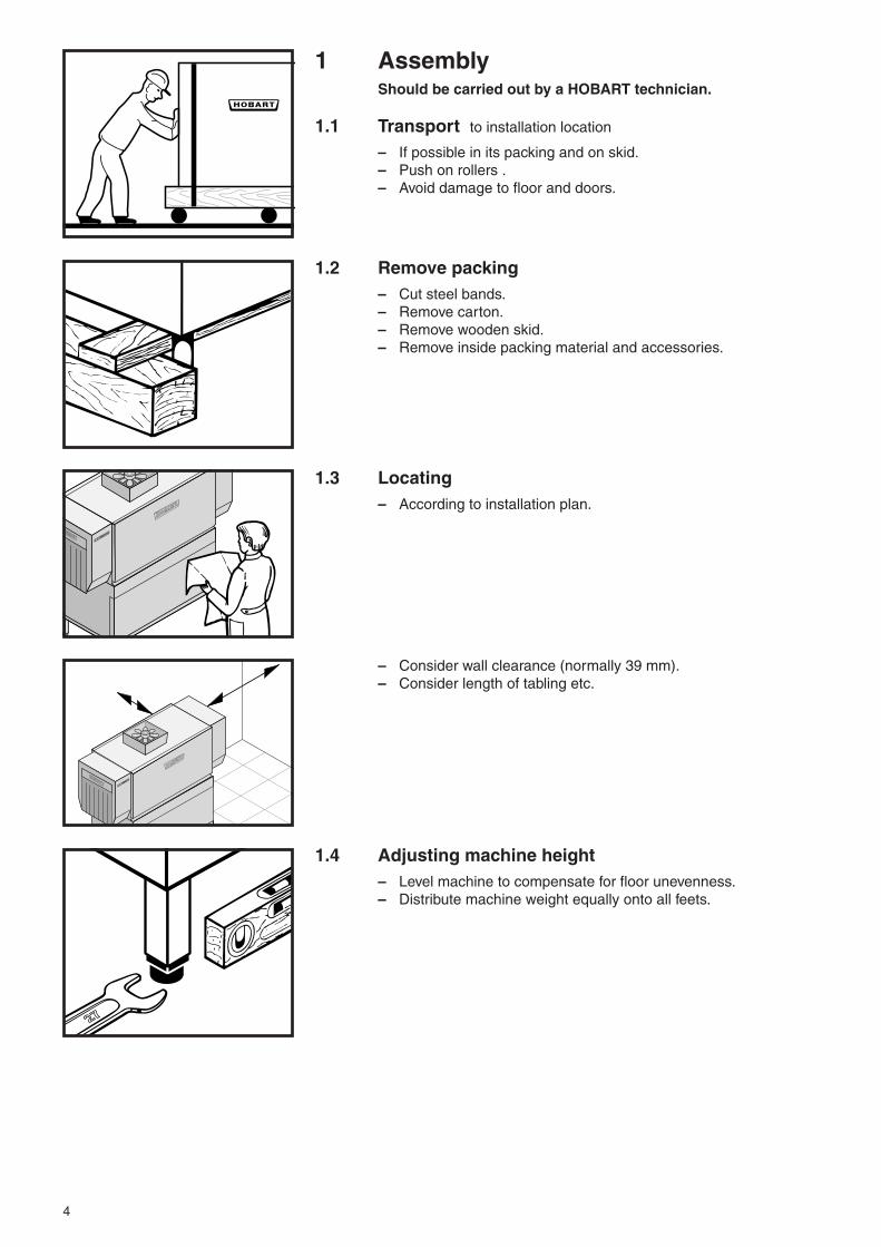
1 AssemblyShould be carried out by a HOBART technician.
1.1 Transport to installation location
– If possible in its packing and on skid.– Push on rollers .– Avoid damage to floor and doors.
1.2 Remove packing– Cut steel bands.– Remove carton.– Remove wooden skid.– Remove inside packing material and accessories.
1.3 Locating– According to installation plan.
– Consider wall clearance (normally 39 mm).– Consider length of tabling etc.
1.4 Adjusting machine height– Level machine to compensate for floor unevenness.– Distribute machine weight equally onto all feets.

5
12
1.5 Attach dish rack tables and accessories– See separate instructions.– Seal screw holes.
– Allow a slight inclination to the machine (if needed, adjust levelby turning the feet).
– Pay attention that the rack track level of the machine is thesame as the table or roller conveyor level. (This means that the"dogs" on the rack transportation must extend above the tablelevel by more than 12 mm.)
– Table end switch:Wiring to control box must be protected.
– Tables on rollers including end switch:Close the connector of the cable and lock it.
6
A
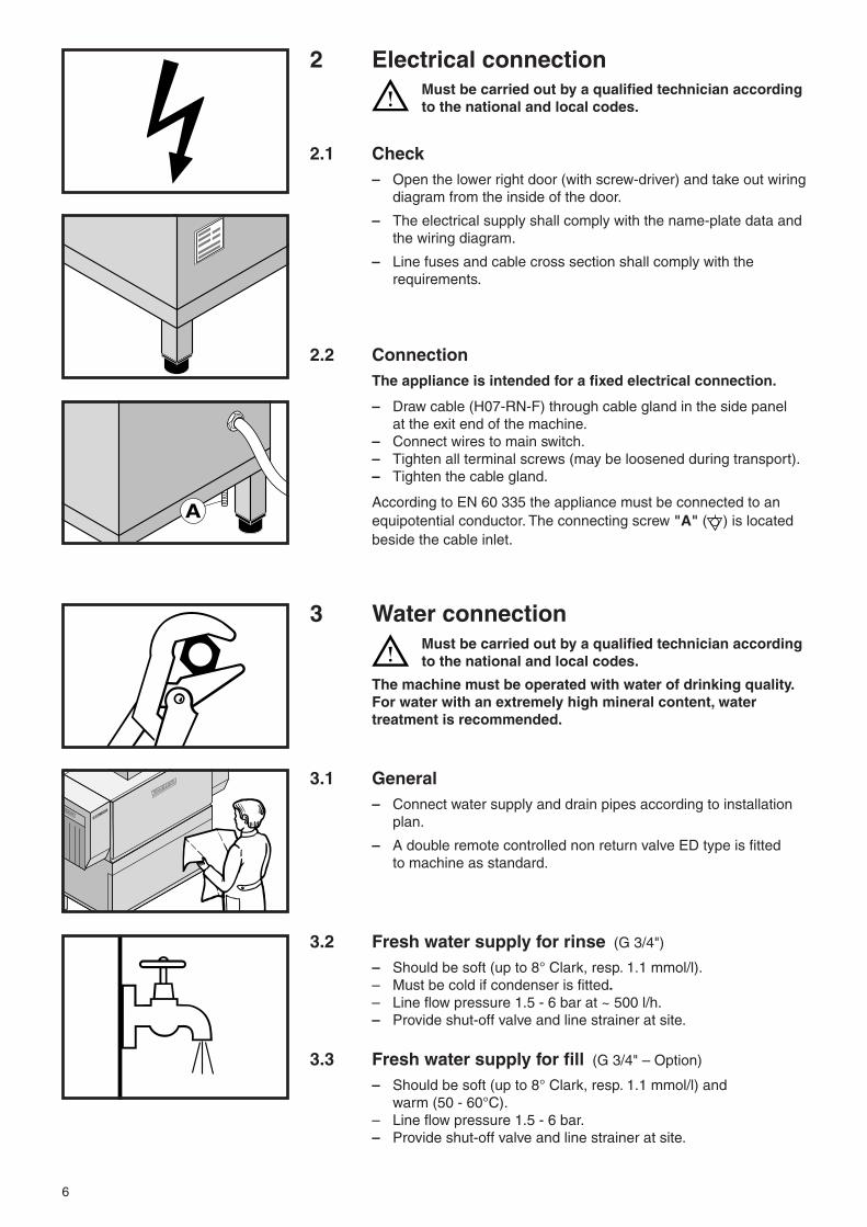
2 Electrical connectionMust be carried out by a qualified technician accordingto the national and local codes.
2.1 Check– Open the lower right door (with screw-driver) and take out wiring
diagram from the inside of the door.
– The electrical supply shall comply with the name-plate data andthe wiring diagram.
– Line fuses and cable cross section shall comply with therequirements.
2.2 ConnectionThe appliance is intended for a fixed electrical connection.
– Draw cable (H07-RN-F) through cable gland in the side panelat the exit end of the machine.
– Connect wires to main switch.– Tighten all terminal screws (may be loosened during transport).– Tighten the cable gland.
According to EN 60 335 the appliance must be connected to anequipotential conductor. The connecting screw "A" ( ) is locatedbeside the cable inlet.
3 Water connectionMust be carried out by a qualified technician accordingto the national and local codes.
The machine must be operated with water of drinking quality.For water with an extremely high mineral content, watertreatment is recommended.
3.1 General– Connect water supply and drain pipes according to installation
plan.
– A double remote controlled non return valve ED type is fittedto machine as standard.
3.2 Fresh water supply for rinse (G 3/4")
– Should be soft (up to 8° Clark, resp. 1.1 mmol/l).– Must be cold if condenser is fitted.– Line flow pressure 1.5 - 6 bar at ~ 500 l/h.– Provide shut-off valve and line strainer at site.
3.3 Fresh water supply for fill (G 3/4" – Option)
– Should be soft (up to 8° Clark, resp. 1.1 mmol/l) andwarm (50 - 60°C).
– Line flow pressure 1.5 - 6 bar.– Provide shut-off valve and line strainer at site.
7
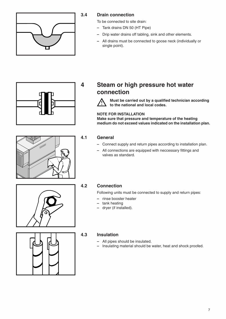
3.4 Drain connectionTo be connected to site drain:
– Tank drains DN 50 (HT Pipe)
– Drip water drains off tabling, sink and other elements.
– All drains must be connected to goose neck (individually orsingle point).
4 Steam or high pressure hot waterconnection
Must be carried out by a qualified technician accordingto the national and local codes.
NOTE FOR INSTALLATIONMake sure that pressure and temperature of the heatingmedium do not exceed values indicated on the installation plan.
4.1 General– Connect supply and return pipes according to installation plan.
– All connections are equipped with neccessary fittings andvalves as standard.
4.2 ConnectionFollowing units must be connected to supply and return pipes:
– rinse booster heater– tank heating– dryer (if installed).
4.3 Insulation– All pipes should be insulated.– Insulating material should be water, heat and shock proofed.
8
10 c
m
5 Exhaust connection– Connection must be carried out in conjunction with competent
ventilation engineer.– Please pay attention to notes on the service drawing.
5.1 Exhaust into the kitchen(only possible in connection with PROVENT-Heat Pump Systemand sufficient room ventilation)
– Avoid condensate damage by mixing exhausts from vent outletof the machine, directly with room air (air distributor).
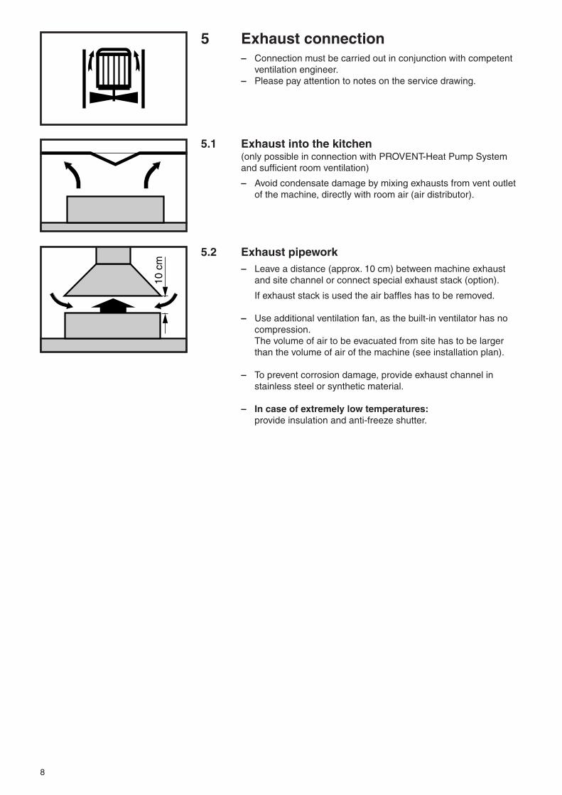
5.2 Exhaust pipework– Leave a distance (approx. 10 cm) between machine exhaust
and site channel or connect special exhaust stack (option).
If exhaust stack is used the air baffles has to be removed.
– Use additional ventilation fan, as the built-in ventilator has nocompression.The volume of air to be evacuated from site has to be largerthan the volume of air of the machine (see installation plan).
– To prevent corrosion damage, provide exhaust channel instainless steel or synthetic material.
– In case of extremely low temperatures:provide insulation and anti-freeze shutter.
9
6 Dispensersof detergent and rinse agent
– Normally, dispensers and controls are delivered and installedby the detergent and rinse agent suppliers.
– Install dispensers, controls and containers in a way that they areeasy to handle and do not disturb machine operation.
– Rinse agent connection is provided after the rinse boosterheater.
– Terminals are provided on the rear of the right lower front panel(see wiring diagram).
See separate Notes:"Installation Recommendations for Dosing Equipment withconveyorised Rack Type and Flighttype dishwashers".
Use only commercial detergent and rinse agent (suitable forprofessional and industrial operations).Please pay attention to the manufacturers safety rules andinstructions.
10
7 Controls
5 8
6
241 73
EMERGENCYSTOP
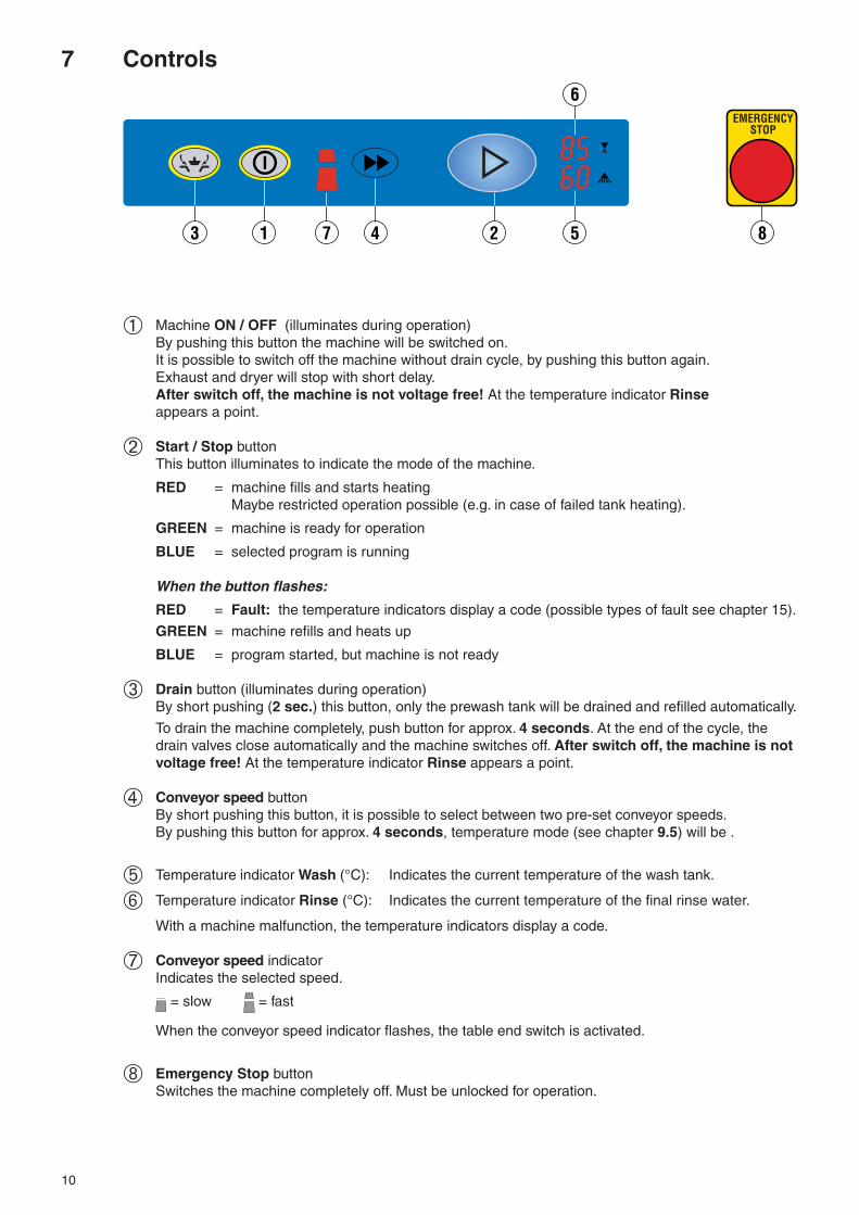
➀ Machine ON / OFF (illuminates during operation)By pushing this button the machine will be switched on.It is possible to switch off the machine without drain cycle, by pushing this button again.Exhaust and dryer will stop with short delay.After switch off, the machine is not voltage free! At the temperature indicator Rinseappears a point.
➁ Start / Stop buttonThis button illuminates to indicate the mode of the machine.
RED = machine fills and starts heatingMaybe restricted operation possible (e.g. in case of failed tank heating).
GREEN = machine is ready for operation
BLUE = selected program is running
When the button flashes:
RED = Fault: the temperature indicators display a code (possible types of fault see chapter 15).
GREEN = machine refills and heats up
BLUE = program started, but machine is not ready
➂ Drain button (illuminates during operation)By short pushing (2 sec.) this button, only the prewash tank will be drained and refilled automatically.
To drain the machine completely, push button for approx. 4 seconds. At the end of the cycle, thedrain valves close automatically and the machine switches off. After switch off, the machine is notvoltage free! At the temperature indicator Rinse appears a point.
➃ Conveyor speed buttonBy short pushing this button, it is possible to select between two pre-set conveyor speeds.By pushing this button for approx. 4 seconds, temperature mode (see chapter 9.5) will be .
➄ Temperature indicator Wash (°C): Indicates the current temperature of the wash tank.
➅ Temperature indicator Rinse (°C): Indicates the current temperature of the final rinse water.
With a machine malfunction, the temperature indicators display a code.
➆ Conveyor speed indicatorIndicates the selected speed.
= slow = fast
When the conveyor speed indicator flashes, the table end switch is activated.
➇ Emergency Stop buttonSwitches the machine completely off. Must be unlocked for operation.

11
8 First runMust be carried out to adjust and check machine functions.
Must be carried out by a qualifiedtechnician.
8.1 Preparation– Set main switch to "0“.
– Check if detergent and rinse agent containers are filled.The adjustment of detergent and rinse agent concentrationshould be carried out by the chemical supplier.
– Open shut-off valves at site.
– Open control box and switch on all circuit breakers and motorprotection switches.
– Switch on main switch.– Switch on site exhaust extraction (if fitted).– Close inspection doors.
8.2 Fill rinse booster heater– Push the ON/OFF button, the button illuminates. At the tem-
perature indicator Rinse ➅ appears "boF" and flashes.The rinse booster heater has to be filled as described in thefollowing text.
– Push the ON/OFF button again, to switch off the machine.
– Open door, push Drain button and Conveyor speed buttonsimultaneously until at the temperature indicator Rinse ➅appears again "boF".
– Push Start / Stop button. At the temperature indicator Wash ➄appears "- - 1". Wait until the indicator displays "- - 0".
– Close door, the indicators go out.For machine operation see chapter 9.
8.3 Check– Direction of rotation of motors (see direction sign):
- pumps- dryer (if fitted)
If motor runs against the indicated direction, interchange2 phases at terminal.
– Check and eliminate possible leakages on:- drain- heating pipework and water supply pipework- machine housing, bottom of tanks, exhaust system
8.4 AutotimerWash, rinse and dryer (if fitted) operate only if racks are passingthrough the machine.These functions switch off automatically if no further racks follow.
Exhaust, dryer and conveyor switch off with delay. The delay timescan be adjusted by authorized Service Technicians.
12
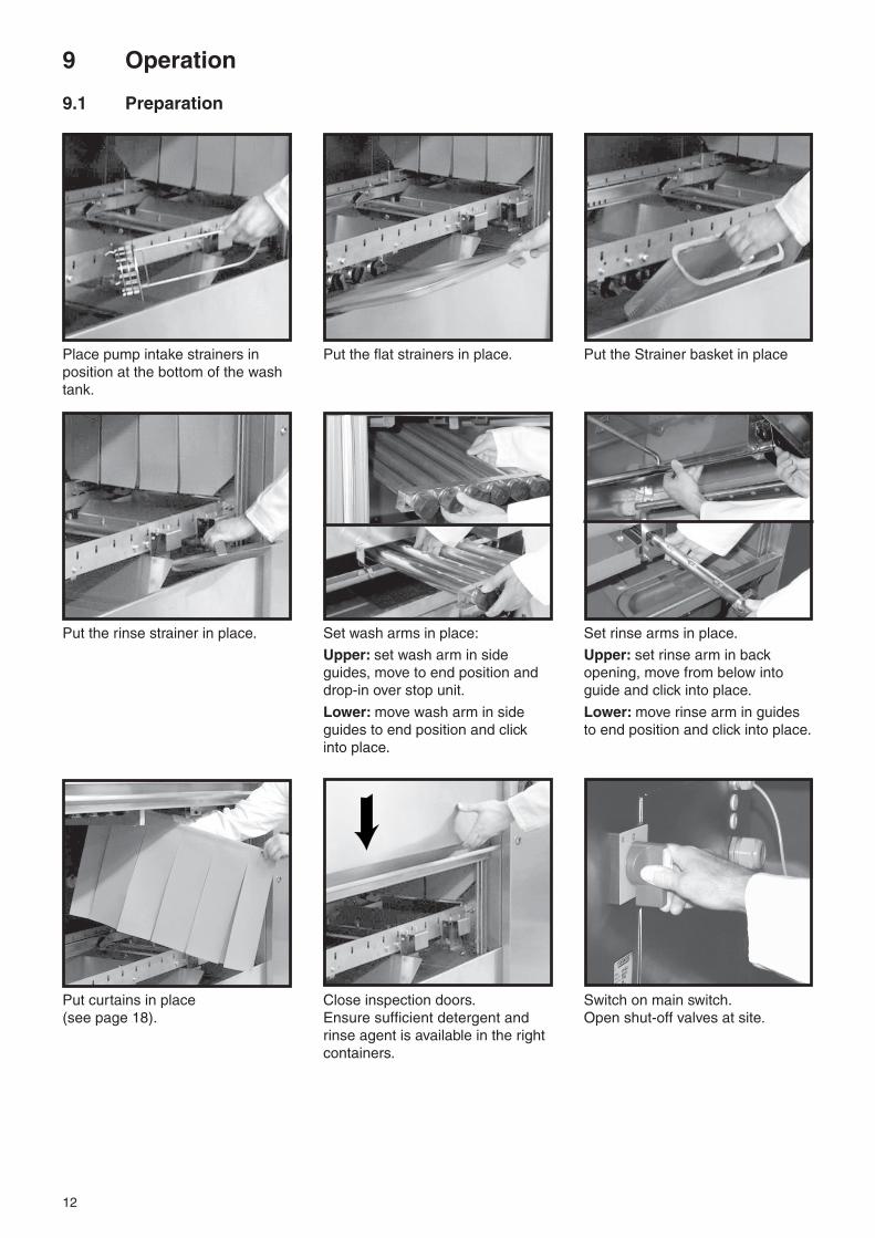
Place pump intake strainers in Put the flat strainers in place. Put the Strainer basket in placeposition at the bottom of the washtank.
Put the rinse strainer in place. Set wash arms in place: Set rinse arms in place.
Upper: set wash arm in side Upper: set rinse arm in backguides, move to end position and opening, move from below intodrop-in over stop unit. guide and click into place.
Lower: move wash arm in side Lower: move rinse arm in guidesguides to end position and click to end position and click into place.into place.
Put curtains in place Close inspection doors. Switch on main switch.(see page 18). Ensure sufficient detergent and Open shut-off valves at site.
rinse agent is available in the rightcontainers.
9 Operation
9.1 Preparation

13
9.2 Racking
When loading platesconsider the machine direction.
Push the ON / OFF button, tank will be filled.The Start / Stop button ➁ illuminates red during fill and heating cycle.This process can take several minutes.
When the Start button changes to green light, machine is ready foroperation.
14
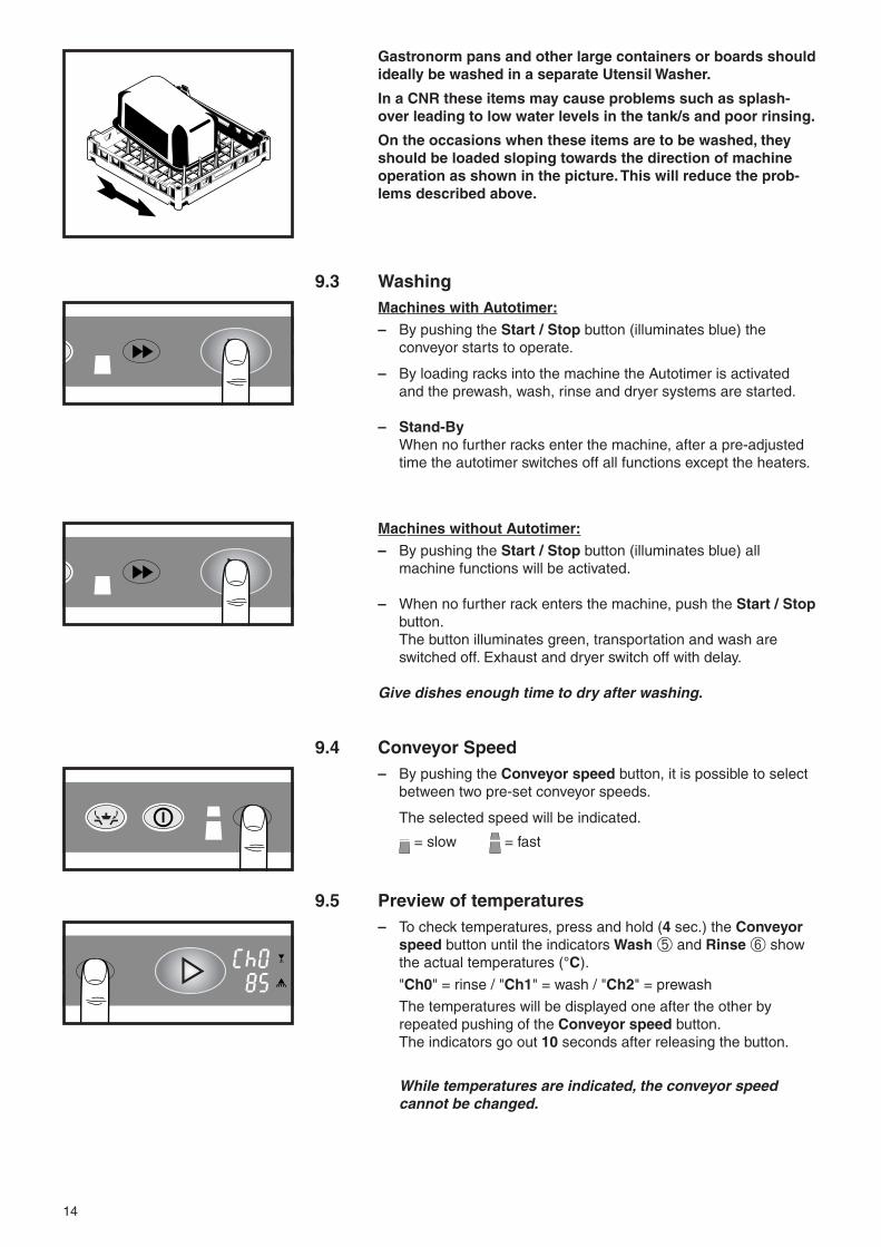
9.3 WashingMachines with Autotimer:
– By pushing the Start / Stop button (illuminates blue) theconveyor starts to operate.
– By loading racks into the machine the Autotimer is activatedand the prewash, wash, rinse and dryer systems are started.
– Stand-ByWhen no further racks enter the machine, after a pre-adjustedtime the autotimer switches off all functions except the heaters.
Machines without Autotimer:
– By pushing the Start / Stop button (illuminates blue) allmachine functions will be activated.
– When no further rack enters the machine, push the Start / Stopbutton.The button illuminates green, transportation and wash areswitched off. Exhaust and dryer switch off with delay.
Give dishes enough time to dry after washing.
9.4 Conveyor Speed– By pushing the Conveyor speed button, it is possible to select
between two pre-set conveyor speeds.
The selected speed will be indicated.
= slow = fast
9.5 Preview of temperatures– To check temperatures, press and hold (4 sec.) the Conveyor
speed button until the indicators Wash ➄ and Rinse ➅ showthe actual temperatures (°C).
"Ch0" = rinse / "Ch1" = wash / "Ch2" = prewash
The temperatures will be displayed one after the other byrepeated pushing of the Conveyor speed button.The indicators go out 10 seconds after releasing the button.
While temperatures are indicated, the conveyor speedcannot be changed.
Gastronorm pans and other large containers or boards shouldideally be washed in a separate Utensil Washer.
In a CNR these items may cause problems such as splash-over leading to low water levels in the tank/s and poor rinsing.
On the occasions when these items are to be washed, theyshould be loaded sloping towards the direction of machineoperation as shown in the picture. This will reduce the prob-lems described above.
15
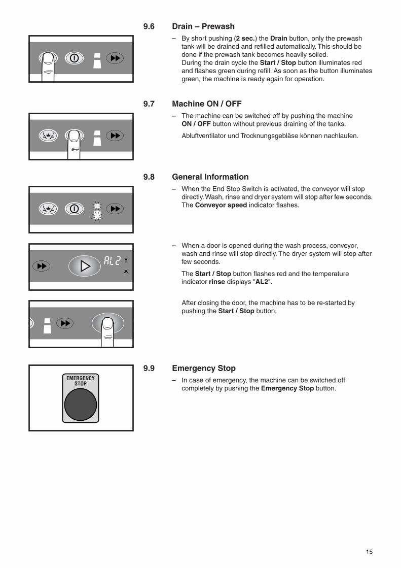
9.6 Drain – Prewash– By short pushing (2 sec.) the Drain button, only the prewash
tank will be drained and refilled automatically. This should bedone if the prewash tank becomes heavily soiled.During the drain cycle the Start / Stop button illuminates redand flashes green during refill. As soon as the button illuminatesgreen, the machine is ready again for operation.
9.7 Machine ON / OFF– The machine can be switched off by pushing the machine
ON / OFF button without previous draining of the tanks.
Abluftventilator und Trocknungsgebläse können nachlaufen.
9.8 General Information– When the End Stop Switch is activated, the conveyor will stop
directly. Wash, rinse and dryer system will stop after few seconds.The Conveyor speed indicator flashes.
– When a door is opened during the wash process, conveyor,wash and rinse will stop directly. The dryer system will stop afterfew seconds.
The Start / Stop button flashes red and the temperatureindicator rinse displays "AL2".
After closing the door, the machine has to be re-started bypushing the Start / Stop button.
9.9 Emergency Stop– In case of emergency, the machine can be switched off
completely by pushing the Emergency Stop button.
EMERGENCYSTOP
16
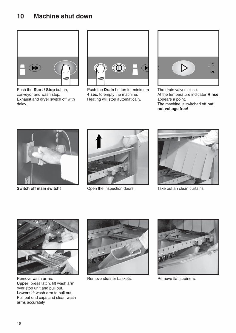
10 Machine shut down
Push the Start / Stop button, Push the Drain button for minimum The drain valves close.conveyor and wash stop. 4 sec. to empty the machine. At the temperature indicator RinseExhaust and dryer switch off with Heating will stop automatically. appears a point.delay. The machine is switched off but
not voltage free!
Switch off main switch! Open the inspection doors. Take out an clean curtains.
Remove wash arms: Remove strainer baskets. Remove flat strainers.Upper: press latch, lift wash armover stop unit and pull out.Lower: lift wash arm to pull out.Pull out end caps and clean washarms accurately.

17
Remove pump intake strainers. Remove rinse strainer. Remove rinse arms:Upper: pull spring towards frontand remove rinse arm.Lower: lift rinse arm and pull out.Control nozzle openings and cleanif necessary.
Hose down and clean the interior Clean once a month: Hose down condensers.of the machine (particulary the Remove the cover at the top of thebottom of wash and prewash tank) condensers and slide away theto avoid any waste remaining. exhaust housing.
To empty the tanks, switch on main Switch off the main switch andswitch and push the Drain button close the shut-off valves.for 4 seconds.The drain valves will be opened Leave the inspection doors openagain. Wait until the tanks are for ventilation.completely emptied, than:
Hose down and brush the strainers – do not knock themto dislodge food soil! They could be damaged.
Never hose down theexterior of the machine.
To clean the machinedo not use any chloric,
acidic or abrasive productsor metallic brushs.

18
781 067-1
429
CDCCDS
1
630
655
781 067-2
4954
630
655
781 284-1
292 3
630
655
781 033-1
325 360-7 325 360-7325 360-7325 360-6
419 2
660
645
AR
421 3
LE S
1 2 2 33 1 3 3 1 31 23
C
11 Position of curtainsIllustrations above are based on left-to-right operating machines.The position of the curtains is mirror imaged for right-to-left operation.
Prewash modules
Wash modul
Dryer modules

19
12 Heatpump CHP 18 (Option)
Cleaning (half-yearly)
Should be carried out by an authorizedtechnician!
Switch off main switch !
Remove the upper housing panels of the machine and the coversof the heat pump.
ATTENTION !Parts of the heat pump can be hot!
Hose down condensers and evaporator!
Do not use steam or high pressure cleaner.Avoid damages!
Fins are sharp!Danger of injury – use protection gloves!
After cleaning put covers and panels back into place.

20
13 Maintenance
For trouble free operation we recommend an inspection ormaintenance contract by qualified Service technicians.
14 Frost preventionMust be carried out by a qualified technician.
– Drain machine by pushing the Drain button.
– Set main switch to "0".
– Set counter C28 to "0" and save.
Alternative: disconnect the contactors of the heating elementsfor the el. rinse booster.
All tanks, water pipework and armatures must be totally drained.
– Turn out plug for the drain fitting of rinse booster heater.– Loosen unions next to fill valve.– Drain site water pipework.– Drain traps of drain system.
– Steam / hot water heated machines:drain all heating coils and pipes.
– The Condenser – if fitted – must be blown out withcompressed air.
Reset for operation:– Open shut-off valves at site.– Switch on main switch.
– Open door, push Drain button and Conveyor speed buttonsimultaneously until at the temperature indicators "boF"and "- - 0" appears.
– Push Start / Stop button (at the temperature indicator Washappears "- - 1") and hold until water sprays out of rinse armnozzles.
– Close door.
– Set main switch to "0".
– Connect the contactors of the heating elements for the el. rinsebooster.
21
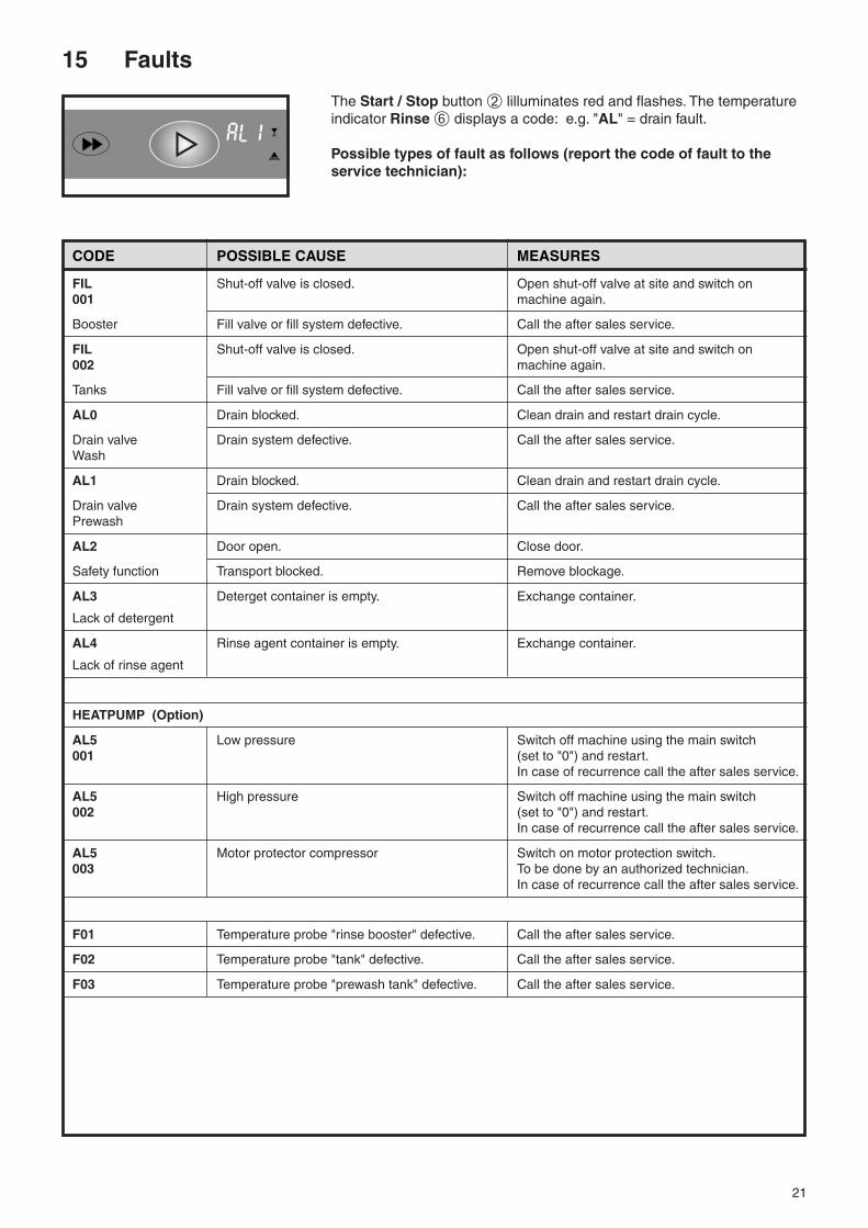
15 Faults
The Start / Stop button ➁ lilluminates red and flashes. The temperatureindicator Rinse ➅ displays a code: e.g. "AL" = drain fault.
Possible types of fault as follows (report the code of fault to theservice technician):
CODE POSSIBLE CAUSE MEASURES
FIL Shut-off valve is closed. Open shut-off valve at site and switch on001 machine again.
Booster Fill valve or fill system defective. Call the after sales service.
FIL Shut-off valve is closed. Open shut-off valve at site and switch on002 machine again.
Tanks Fill valve or fill system defective. Call the after sales service.
AL0 Drain blocked. Clean drain and restart drain cycle.
Drain valve Drain system defective. Call the after sales service.Wash
AL1 Drain blocked. Clean drain and restart drain cycle.
Drain valve Drain system defective. Call the after sales service.Prewash
AL2 Door open. Close door.
Safety function Transport blocked. Remove blockage.
AL3 Deterget container is empty. Exchange container.
Lack of detergent
AL4 Rinse agent container is empty. Exchange container.
Lack of rinse agent
HEATPUMP (Option)
AL5 Low pressure Switch off machine using the main switch001 (set to "0") and restart.
In case of recurrence call the after sales service.
AL5 High pressure Switch off machine using the main switch002 (set to "0") and restart.
In case of recurrence call the after sales service.
AL5 Motor protector compressor Switch on motor protection switch.003 To be done by an authorized technician.
In case of recurrence call the after sales service.
F01 Temperature probe "rinse booster" defective. Call the after sales service.
F02 Temperature probe "tank" defective. Call the after sales service.
F03 Temperature probe "prewash tank" defective. Call the after sales service.

22
16 Troubleshooting guide
TYPE OF FAILURE POSSIBLE CAUSE REMEDY
tank fill too slow line strainer of fill clogged clean line strainer
solenoid valve defective call the after sales service
insufficient supply pressure provide correct services
tank not filled to correct fill cycle too short call the after sales servicelevel
steam escapes from exhaust extraction too low call the after sales serviceloading or exit section
wrong position of curtains check curtains
temperatures too low too much exhaust extraction call the after sales service
heaters defective check heaters, steam or high pressurehot water supply systems and thermostatsCall the after sales service.
dishes soiled after strainers wrongly positioned check strainersdishwashing
curtains not fitted or wrongly placed check curtains (see chapter 11)
wash jets clogged clean the wash arms
too low detergent concentration increase detergent dispensing
too much foam use non-foaming detergent only
excessive food debris entering machine check pre-scrapping procedure
temperatures too low check heating system
motor protection switch tripped call the after sales service
conveyor speed too high select lower speed
streaks and spots on strainers wrongly positioned check strainersthe dishes
wash water splashes into rinse check curtains (see chapter 11)section
rinse jets clogged clean rinse jets
inadequate rinse agent dispensing get the dispenser adjusted
too high mineral content of rinse water use of demineralized waterrecommended
dishes do not dry incorrect temperature or humidity check heater and blower ofof drying air drying unit
conveyor speed too high select lower speed
dishware still greasy increase detergent concentration
drops on dishes inadequate rinse agent concentration get concentration increased
dishes tilt over water pressure from below too high replace reducer between lowerwash arm and wash pipe
upper wash arms clogged remove wash arms and clean
items too light use cover on racks
machine out of order main / emergency switch switched off, switch on main / emergency switch,power supply completely cut-off re-start machine
power failure re-start machine, when power availableagain

23

As continued product improvement is a policy of HOBART, specifications are subject to change without notice.
Printed in Germany AG-21264-B-06-04-PC