design of scale-model floating wind turbine platforms · design of scale-model floating wind...
TRANSCRIPT
0
DESIGN OF SCALE-MODEL FLOATING WIND TURBINE PLATFORMS
A Major Qualifying Project
submitted to the Faculty of
WORCESTER POLYTECHNIC INSTITUTE
in partial fulfillment of the requirements for the
Degree of Bachelor of Science
by
Diana Berlo
Christopher Gabrielson
Stephen Hanly
Michal Parzych
Michael Sacco
Ryan Sebastian
Date: March 16, 2010
Professor David J. Olinger, Advisor
I
ABSTRACT The goal of this project was to design and build scale models of a tension leg platform and a shallow
draft barge floating wind turbine, and to perform hydrodynamic tests. The models are scaled 100:1
from prototypes developed by the National Renewable Energy Laboratory and Massachusetts Institute
of Technology. This report details the design process for the model turbine components, including
revisions and suggestions for improvement. Components were modeled in SolidWorks, then fabricated
using a rapid prototyping system or machine tools. A data acquisition system (accelerometer,
inclinometer, and load cell sensors) developed by a concurrent master’s student project were integrated
into the models to collect data during testing. Models were tested in fresh water to determine
buoyancy, draft, and response to various wave conditions. Successful preliminary tests were performed
in the 6 foot by 6 foot flume at Alden Research Laboratory with the turbine models in a towing
condition; the configuration used to transport the turbines from the shore to the desired location of
operation. Future testing using the developed scale models will study operating conditions where the
platforms are moored with cables to the ocean floor.
Certain materials are included under the fair use exemption of the U.S. Copyright Law and have been prepared
according to the fair use guidelines and are restricted from further use.
II
TABLE OF CONTENTS
ABSTRACT ....................................................................................................................................................... I
TABLE OF CONTENTS ..................................................................................................................................... II
TABLE OF FIGURES ....................................................................................................................................... IV
TABLE OF TABLES ......................................................................................................................................... VI
1. INTRODUCTION ......................................................................................................................................... 1
2. BACKGROUND ........................................................................................................................................... 3
2.1. Wind Energy ....................................................................................................................................... 3
2.1.1. Offshore Wind Power ................................................................................................................. 3
2.2. Floating Turbine Designs .................................................................................................................... 4
2.2.1. StatoilHydro ................................................................................................................................ 5
2.2.2. Previous Floating Wind Turbine Tests ........................................................................................ 6
2.2.3. Major Qualifying Project Designs ................................................................................................ 6
3. PROJECT OBJECTIVES ................................................................................................................................ 9
4. DESIGN AND MANUFACTURE ................................................................................................................. 10
4.1. TENSION LEG PLATFORM ................................................................................................................. 14
4.1.1. Tank ........................................................................................................................................... 14
4.1.2. Cover ......................................................................................................................................... 16
4.1.3. Internal Support Structure ........................................................................................................ 17
4.1.4. Water Cover .............................................................................................................................. 21
4.2. MODIFIED VERSION OF TENSION LEG PLATFORM ........................................................................... 22
4.2.1. Leg Assembly ............................................................................................................................. 22
4.2.2. Tank ........................................................................................................................................... 25
4.2.3. Cover ......................................................................................................................................... 28
4.2.4. Complete Modified TLP ............................................................................................................. 30
4.3. SHALLOW DRAFT BARGE .................................................................................................................. 32
4.3.1. Tank ........................................................................................................................................... 32
4.3.2. Cover ......................................................................................................................................... 33
4.3.3. Internal Support Structure ........................................................................................................ 34
4.4. COMMON ELEMENTS BETWEEN THE TLP AND SDB ........................................................................ 36
4.4.1. Tower ........................................................................................................................................ 37
III
4.4.2. Rotor and Nacelle Weight Change ............................................................................................ 39
4.4.3. Concrete .................................................................................................................................... 43
4.4.4. Painting ..................................................................................................................................... 44
5. TESTING ................................................................................................................................................... 45
6. RESULTS ................................................................................................................................................... 49
7. CONCLUSIONS ......................................................................................................................................... 51
8. FUTURE WORK ........................................................................................................................................ 52
REFERENCES ................................................................................................................................................ 54
APPENDIX A: Initial Tension Leg Platform Leg Design ................................................................................ 55
IV
TABLE OF FIGURES
Figure 1. Energy Consumption in the U.S., 2008. From Reference 1 ............................................................ 1
Figure 2. United States 50-Meter Wind Resource Map. From Reference 2 ................................................. 2
Figure 3. Floating Wind Turbine Designs. From Reference 11. .................................................................... 5
Figure 4. Tension Leg Platform Tank. .......................................................................................................... 14
Figure 5. Sketch of the Initial TLP Tank Design (dimensions in inches) ...................................................... 15
Figure 6. Sketch of Finalized Original Design for TLP Tank (dimensions in inches) .................................... 16
Figure 7. SolidWorks Image of Original TLP Tank ....................................................................................... 16
Figure 8. Cutout Image of the Mating Characteristics between the TLP Cover and Base .......................... 17
Figure 9. TLP Cover...................................................................................................................................... 17
Figure 10. TLP Cover Deflecting as a Result of Tower Movement. ............................................................. 18
Figure 11. TLP Internal Support Structure .................................................................................................. 19
Figure 12. TLP Support Structure Model..................................................................................................... 19
Figure 13. Support Structure Wire Frame View Showing Sensor Mount Platform. ................................... 20
Figure 14. TLP Support Structure and Cover ............................................................................................... 21
Figure 15. SolidWorks Screenshot of Water Cover ..................................................................................... 22
Figure 16. Modified TLP Leg Design ............................................................................................................ 23
Figure 17. Fabricated TLP Leg Assembly ..................................................................................................... 23
Figure 18. Drawing of Leg Assembly Connector (dimensions in inches) .................................................... 24
Figure 19. Section View of the Modified TLP Tank ..................................................................................... 26
Figure 20. Crack Modified TLP Tank ............................................................................................................ 27
Figure 21. Sketch of Modified TLP Tank (dimensions in inches) ................................................................. 27
Figure 22. New TLP Tank Model ................................................................................................................. 28
Figure 23. Sketch of the Modified TLP Cover (dimensions in inches) ......................................................... 29
Figure 24. New TLP Cover, Top ................................................................................................................... 29
Figure 25. New TLP Cover, Bottom ............................................................................................................. 30
Figure 26. Cross-Section of New TLP Layout ............................................................................................... 30
Figure 27. New TLP Tank with Leg Assembly .............................................................................................. 31
Figure 28. Shallow Draft Barge ................................................................................................................... 32
Figure 29. SBD Cover Portion ...................................................................................................................... 33
Figure 30. SDB Cover, SolidWorks Model ................................................................................................... 34

V
Figure 31. SDB Cover ................................................................................................................................... 34
Figure 32. SDB cover with support; bottom surface of cover is shown ...................................................... 35
Figure 33. SDB cover with support. ............................................................................................................ 35
Figure 34. SDB Large Cover Support ........................................................................................................... 36
Figure 35. TLP and SDB Tanks with Tower .................................................................................................. 37
Figure 36. Tower Slot/Teeth ....................................................................................................................... 38
Figure 37. Tower Tapered ........................................................................................................................... 38
Figure 38. Tower Indent .............................................................................................................................. 39
Figure 39. Nacelle and Rotor Weight .......................................................................................................... 40
Figure 40. Rotor and nacelle weight with Accelerometer and Inclinometer .............................................. 40
Figure 41. SolidWorks Model of Rotor and nacelle weight Version 2 ........................................................ 41
Figure 42. SolidWorks Model of Rotor and nacelle weight Version 2, with Tower Mount Attachment .... 42
Figure 43. Rotor and nacelle weight with Sensors and Ballast Weights ..................................................... 43
Figure 44. TLP Float Test in Water Tunnel .................................................................................................. 45
Figure 45. SDB Float Test in Water Tunnel ................................................................................................. 46
Figure 46. SDB Model Wired for Initial Testing in Higgins Laboratories ..................................................... 47
Figure 47. Water Flume, Alden Laboratories .............................................................................................. 48
Figure 48. Screenshot of Video and LabVIEW Graphs for Test S30 ............................................................ 49
Figure 49. TLP Leg Model, SolidWorks ........................................................................................................ 56
Figure 50. TLP Leg Model ............................................................................................................................ 56
Figure 51. TLP with Leg Attachment ........................................................................................................... 57
Figure 52. TLP with Legs Removed.............................................................................................................. 58
VI
TABLE OF TABLES
Table 1. TLP and SDB Properties, as described in Reference 15 ................................................................... 7
Table 2. Floating Turbine Properties, as described in Reference 15 ............................................................ 8
Table 3. TLP* Prototype and Model Properties .......................................................................................... 12
Table 4. SDB Prototype and Model Properties ........................................................................................... 13
Table 5. Prototype and Model Properties .................................................................................................. 13
Table 6. Model Scale Factors ...................................................................................................................... 13
1
1. INTRODUCTION
Electricity is a primary power source for human civilizations. In the past few decades, however,
concern over the ability to maintain growth of electricity production has increased. Not only do current
methods have negative environmental impacts through the burning of fossil fuels, but also the finite
amount of these resources causes the need for the advancement of current renewable models.
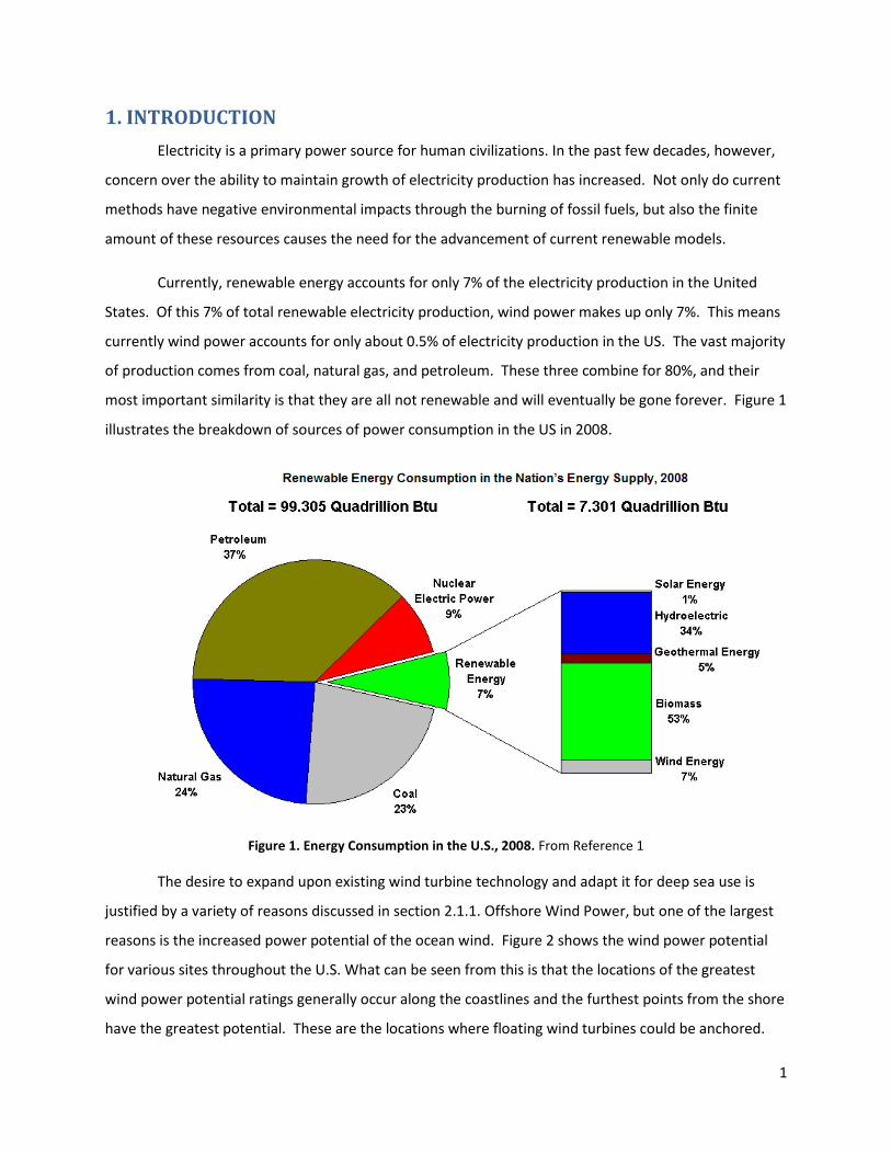
Currently, renewable energy accounts for only 7% of the electricity production in the United
States. Of this 7% of total renewable electricity production, wind power makes up only 7%. This means
currently wind power accounts for only about 0.5% of electricity production in the US. The vast majority
of production comes from coal, natural gas, and petroleum. These three combine for 80%, and their
most important similarity is that they are all not renewable and will eventually be gone forever. Figure 1
illustrates the breakdown of sources of power consumption in the US in 2008.
Figure 1. Energy Consumption in the U.S., 2008. From Reference 1
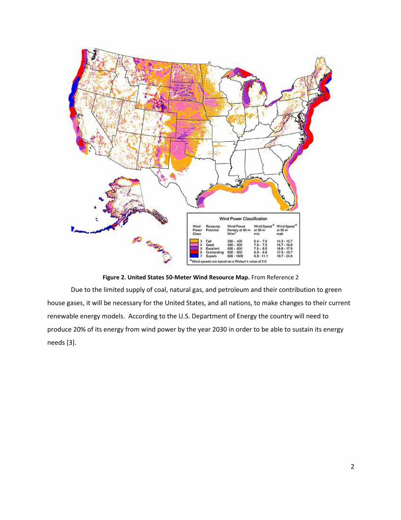
The desire to expand upon existing wind turbine technology and adapt it for deep sea use is
justified by a variety of reasons discussed in section 2.1.1. Offshore Wind Power, but one of the largest
reasons is the increased power potential of the ocean wind. Figure 2 shows the wind power potential
for various sites throughout the U.S. What can be seen from this is that the locations of the greatest
wind power potential ratings generally occur along the coastlines and the furthest points from the shore
have the greatest potential. These are the locations where floating wind turbines could be anchored.
2
Figure 2. United States 50-Meter Wind Resource Map. From Reference 2
Due to the limited supply of coal, natural gas, and petroleum and their contribution to green
house gases, it will be necessary for the United States, and all nations, to make changes to their current
renewable energy models. According to the U.S. Department of Energy the country will need to
produce 20% of its energy from wind power by the year 2030 in order to be able to sustain its energy
needs [3].
3
2. BACKGROUND
2.1. Wind Energy “Wind energy has many benefits, including producing no direct emissions1 while generating
electricity at a reasonable cost. The efficiency, or capacity factor, of wind turbines continually increases
with improved manufacturing processes, siting techniques, and operating procedures. Wind energy is a
resource that is available almost everywhere,2 and unlike most forms of electricity generation, wind
power does not require water and can be used in remote locations that cannot easily or cheaply be
connected to the electricity grid [4]. Despite the objections, such as noise, visual disturbance, and avian
impacts faced by many entities proposing the construction of wind turbines, researchers and scientists
unanimously agree that extracting energy using wind power has substantially fewer adverse effects on
the environment than does the use of fossil fuels [5,6]. Thus, wind energy is a major untapped resource
with great potential.”3
2.1.1. Offshore Wind Power
Offshore wind turbines offer many benefits over land-based turbines, but also have greater
challenges. Offshore wind turbines are located far from property and buildings, so noise and collapse
are insignificant concerns from a human factor standpoint. Wind speeds are often far greater offshore,
as there are no land masses to alter the flow of the air, allowing for greater efficiency and more power
produced. Offshore farms are also more costly to construct, due to the required floating structure and
power distribution lines which must connect the turbines to land [7].
Locating wind turbines far offshore, twenty miles or more, has many benefits. Far offshore wind
farms can be located closer to load centers, reducing the required length of transmission lines; wind
speeds are higher and more consistent away from land; and, due to the curvature of the earth, the
turbines are not visible from land [7,8,9]. Visual and auditory concerns, commonly referred to as
NIMBY, or Not In my Back Yard, is a common concern regarding wind turbines [3]. If wind farms are
1 Arguably, some pollutants are emitted during the process of manufacturing and shipping parts, as well as in the
maintenance of turbines and infrastructure. 2 While wind exists almost everywhere, wind speeds determine whether turbines can effectively capture wind
energy. See http://www.windpoweringamerica.gov/wind_maps.asp for more information about wind resources in the United States. 3This passage was obtained from Berlo, D., Hunt, J., Martori, A., Skelly, J. “Wind Generation on Nantucket,”
Worcester Polytechnic Institute Interactive Qualifying Project, 17 December 2008.
4
situated far offshore, these concerns are negated. Wind turbines can be situated with sufficient space
between in order to prevent air flow interference between turbines, and humans will not be impacted
by the large area that the wind farm encompasses, as they may be with land-based farms [4,10].
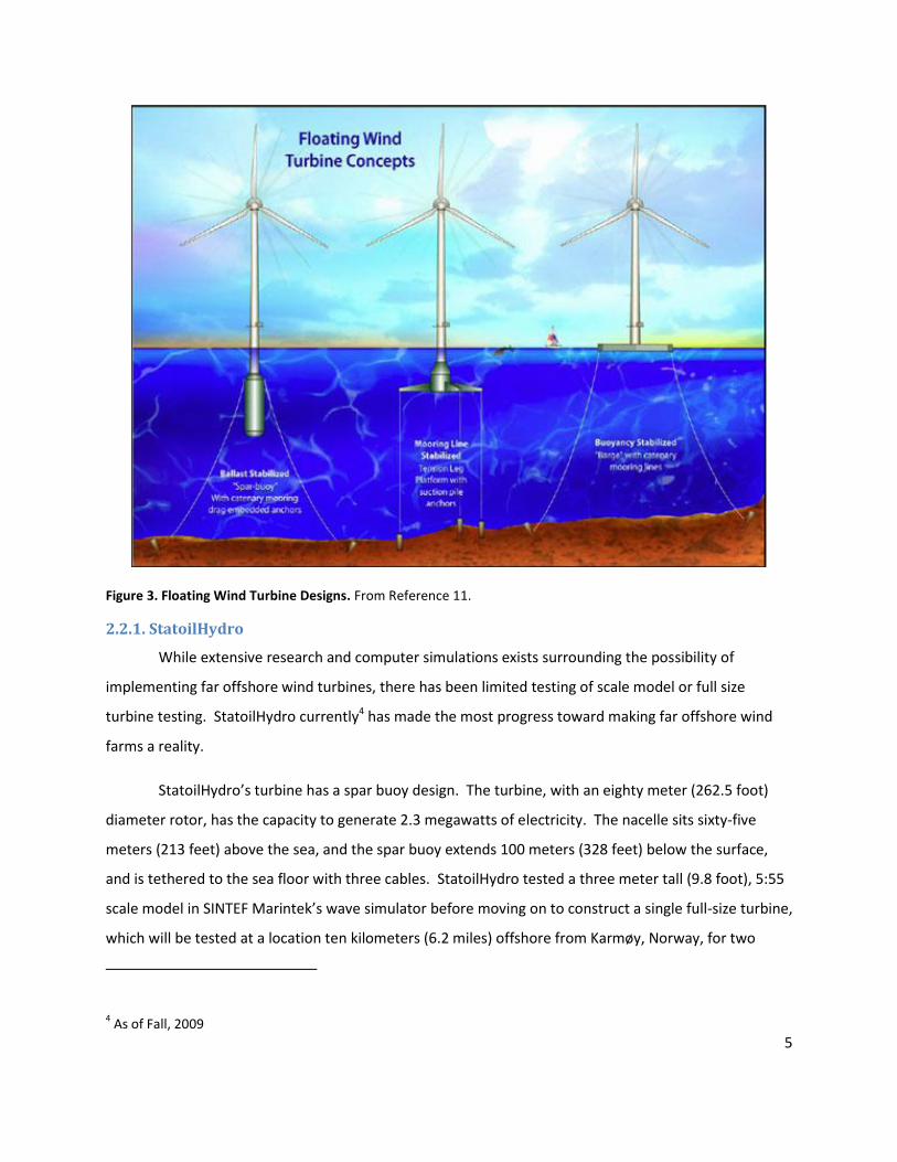
2.2. Floating Turbine Designs Several designs for floating turbines have been studied. Three promising designs are the spar
buoy, tension leg platform, and shallow draft barge. The spar buoy is a ballast-stabilized design which
has a long, cylindrical tank with ballast and a center of gravity below the center of mass [11]. The
tension leg platform (TLP) has additional buoyancy in the tank and uses taut-leg mooring lines to
stabilize the turbine [11,12]. The shallow draft barge (SDB) has a tank which floats on the surface of the
water and has a large waterplane area [11]. The spar buoy and shallow draft barge designs use a
catenary mooring system, which loosely moors the turbine tank to the seafloor to prevent drifting.
Catenary mooring systems are less costly than taut-leg moorings, but require either a large waterplane
area or low center of gravity in order to provide necessary stability. Loose mooring lines also subject the
turbine system to greater motions than taut-leg moorings, increasing the complexity of system
integration. Taut-leg mooring systems are more complex than catenary systems, however taut mooring
lines are beneficial, especially in deeper water, because shorter lengths of mooring line are needed, and
taut lines produce a more stable platform [12]. Figure 3 shows the three current floating wind turbine
designs.
5
Figure 3. Floating Wind Turbine Designs. From Reference 11.
2.2.1. StatoilHydro
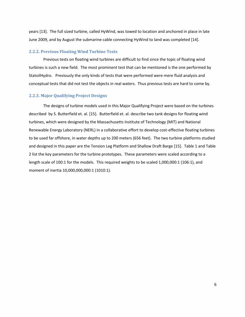
While extensive research and computer simulations exists surrounding the possibility of
implementing far offshore wind turbines, there has been limited testing of scale model or full size
turbine testing. StatoilHydro currently4 has made the most progress toward making far offshore wind
farms a reality.
StatoilHydro’s turbine has a spar buoy design. The turbine, with an eighty meter (262.5 foot)
diameter rotor, has the capacity to generate 2.3 megawatts of electricity. The nacelle sits sixty-five
meters (213 feet) above the sea, and the spar buoy extends 100 meters (328 feet) below the surface,
and is tethered to the sea floor with three cables. StatoilHydro tested a three meter tall (9.8 foot), 5:55
scale model in SINTEF Marintek’s wave simulator before moving on to construct a single full-size turbine,
which will be tested at a location ten kilometers (6.2 miles) offshore from Karmøy, Norway, for two
4 As of Fall, 2009
6
years [13]. The full sized turbine, called HyWind, was towed to location and anchored in place in late
June 2009, and by August the submarine cable connecting HyWind to land was completed [14].
2.2.2. Previous Floating Wind Turbine Tests
Previous tests on floating wind turbines are difficult to find since the topic of floating wind
turbines is such a new field. The most prominent test that can be mentioned is the one performed by
StatoilHydro. Previously the only kinds of tests that were performed were mere fluid analysis and
conceptual tests that did not test the objects in real waters. Thus previous tests are hard to come by.
2.2.3. Major Qualifying Project Designs
The designs of turbine models used in this Major Qualifying Project were based on the turbines
described by S. Butterfield et. al. [15]. Butterfield et. al. describe two tank designs for floating wind
turbines, which were designed by the Massachusetts Institute of Technology (MIT) and National
Renewable Energy Laboratory (NERL) in a collaborative effort to develop cost-effective floating turbines
to be used far offshore, in water depths up to 200 meters (656 feet). The two turbine platforms studied
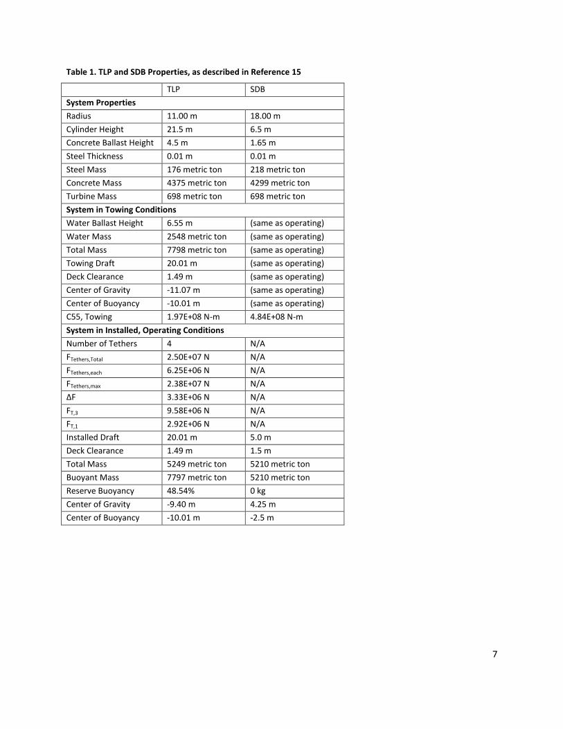
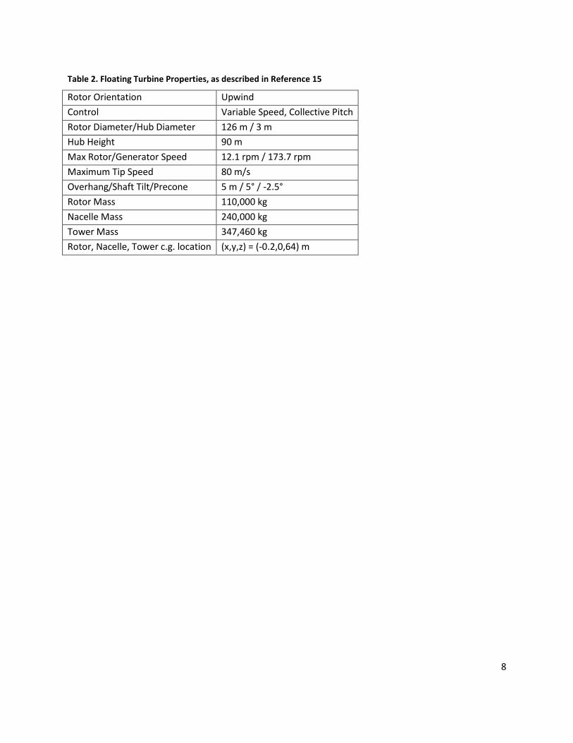
and designed in this paper are the Tension Leg Platform and Shallow Draft Barge [15]. Table 1 and Table
2 list the key parameters for the turbine prototypes. These parameters were scaled according to a
length scale of 100:1 for the models. This required weights to be scaled 1,000,000:1 (106:1), and
moment of inertia 10,000,000,000:1 (1010:1).
7
Table 1. TLP and SDB Properties, as described in Reference 15
TLP SDB
System Properties
Radius 11.00 m 18.00 m
Cylinder Height 21.5 m 6.5 m
Concrete Ballast Height 4.5 m 1.65 m
Steel Thickness 0.01 m 0.01 m
Steel Mass 176 metric ton 218 metric ton
Concrete Mass 4375 metric ton 4299 metric ton
Turbine Mass 698 metric ton 698 metric ton
System in Towing Conditions
Water Ballast Height 6.55 m (same as operating)
Water Mass 2548 metric ton (same as operating)
Total Mass 7798 metric ton (same as operating)
Towing Draft 20.01 m (same as operating)
Deck Clearance 1.49 m (same as operating)
Center of Gravity -11.07 m (same as operating)
Center of Buoyancy -10.01 m (same as operating)
C55, Towing 1.97E+08 N-m 4.84E+08 N-m
System in Installed, Operating Conditions
Number of Tethers 4 N/A
FTethers,Total 2.50E+07 N N/A
FTethers,each 6.25E+06 N N/A
FTethers,max 2.38E+07 N N/A
ΔF 3.33E+06 N N/A
FT,3 9.58E+06 N N/A
FT,1 2.92E+06 N N/A
Installed Draft 20.01 m 5.0 m
Deck Clearance 1.49 m 1.5 m
Total Mass 5249 metric ton 5210 metric ton
Buoyant Mass 7797 metric ton 5210 metric ton
Reserve Buoyancy 48.54% 0 kg
Center of Gravity -9.40 m 4.25 m
Center of Buoyancy -10.01 m -2.5 m
8
Table 2. Floating Turbine Properties, as described in Reference 15
Rotor Orientation Upwind
Control Variable Speed, Collective Pitch
Rotor Diameter/Hub Diameter 126 m / 3 m
Hub Height 90 m
Max Rotor/Generator Speed 12.1 rpm / 173.7 rpm
Maximum Tip Speed 80 m/s
Overhang/Shaft Tilt/Precone 5 m / 5° / -2.5°
Rotor Mass 110,000 kg
Nacelle Mass 240,000 kg
Tower Mass 347,460 kg
Rotor, Nacelle, Tower c.g. location (x,y,z) = (-0.2,0,64) m
9
3. PROJECT OBJECTIVES
MQP Objectives
Examine previous experiments relating to floating wind turbines and floating platform designs
Design and construct a 100:1 scale model of tension leg platform and shallow draft barge
floating turbine prototypes
Integrate instrumentation into models to monitor turbine motion, including platform and tower
frequencies and amplitudes, platform and tower pitch and heave motions, and wave
frequencies and amplitudes while turbine is in towing condition. A concurrent project by
graduate student Eric DeStefano has developed the instrumentation and data acquisition
system for the scale model platforms.
Determine dynamic responses of the floating turbine system to various wave conditions while
turbine is in towing condition
Identify potential vibrational instabilities detrimental to each turbine design
10
4. DESIGN AND MANUFACTURE
The turbines modeled in this MQP are 100:1 scale models of the shallow draft barge and
tensioned leg platform turbine designs described by E.N. Wayman, P.D. Sclavounos, S. Butterfield, J.
Jonkman, and W. Musial in their conference article “Coupled Dynamic Modeling of Floating Wind
Turbine Systems [15].”
To be able to build the scale models of the off shore wind turbines we used the rapid
prototyping machine that is available in the Mechanical Engineering Department at WPI. It is a
Dimension SST 1200 ES rapid prototyping system with soluble support technology. The rapid
prototyping machine is capable of building an object with a base of eight (8) inches by eight (8) inches
and height of twelve (12) inches, with a minimum base thickness of 0.06 inches and wall thickness of
0.03 inches and has Windows XP/Windows Vista and Ethernet TCP/IP 10/100 Base-T network
connectivity. The specifications of the printer limited the design of numerous parts of the turbines to be
built as a solid piece therefore they were split into pieces. The machine fabricates parts based on an
input file. A solid model can be created in SolidWorks or another three-dimensional modeling program,
then the file is saved in .stl format, and is uploaded to the machine. After this, the machine begins to
build the part in bottom up fashion by first layering a plastic support material, then layering the ABS
plastic on top. After the production is complete the separate layers of plastic are visible, and when the
wall thickness is small, it is possible to separate the different layers. Also if the plastic is layered to at
least a 0.5 inch thickness it is sufficiently water proof. However, before the part is complete, the part
must be placed in a container full of fluid that is able to dissolve the support material formed earlier.
This can take from a few hours to a day depending on how thin or how thick the piece was made. It
usually tends to be a shorter waiting period for thicker parts which require less of the support material
thus less time in the fluid.
Initial modeling of the turbine tank and tower was created on a rapid prototyping machine
using acrylonitrile butadiene styrene (ABS) plastic. Ideally the model should be scaled exactly, however
due to the capability of the rapid prototyping machine, high costs of very thin, light, and rigid materials,
and stability concerns, some component weights are not scaled exactly. In order to keep with weight
scaling, the turbine tanks need to have very thin walls, which cannot withstand the forces imposed on
the structure. The tank was constructed with thicker walls and therefore a greater weight. The mass of
ballast concrete and water (in the tensioned leg platform only) in the tanks was altered in order to
11
maintain the correct scaled weight for the tank and ballast system as a whole. Slight differences in
masses of individual components is acceptable, as long as the model’s final mass and center of mass is in
the correct location.
Due to the manufacture method of the rapid prototyping machine, the thin walls of components
were not watertight. ABS cement, containing a combination of methyl ethyl ketone (MEK), acetone, and
ABS solids was used both to bond pieces of plastic together, and also as a waterproof coating. The
bottom surface of both the TLP and SDB were coated with ABS cement. The cement was also added to
the inside of the tanks, up to the height of the concrete ballast, to prevent the water in the concrete
from seeping into the walls of the tank. Table 3, Table 4, and Table 5 list turbine properties – lengths,
weights, centers of gravity – for the prototypes and 1/100th scale models of the shallow draft barge and
tensioned leg platform. Table 6 lists the scale factors used to properly scale the prototype values to
model values.
12
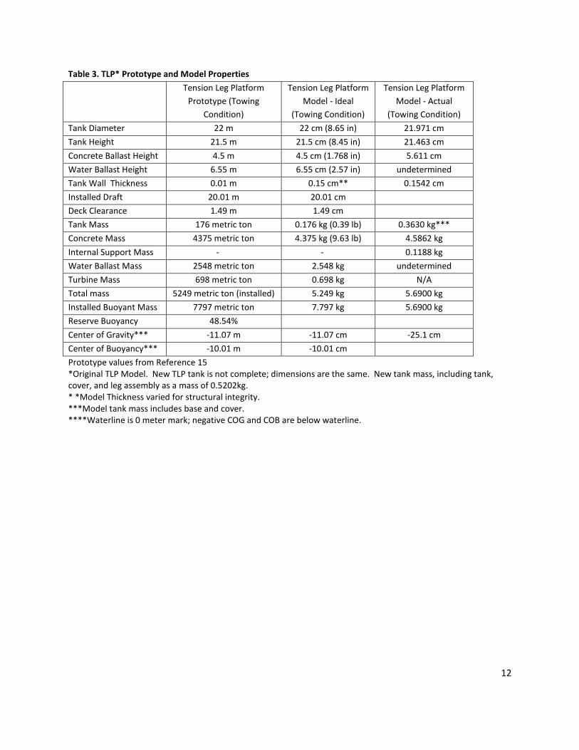
Table 3. TLP* Prototype and Model Properties
Tension Leg Platform
Prototype (Towing
Condition)
Tension Leg Platform
Model - Ideal
(Towing Condition)
Tension Leg Platform
Model - Actual
(Towing Condition)
Tank Diameter 22 m 22 cm (8.65 in) 21.971 cm
Tank Height 21.5 m 21.5 cm (8.45 in) 21.463 cm
Concrete Ballast Height 4.5 m 4.5 cm (1.768 in) 5.611 cm
Water Ballast Height 6.55 m 6.55 cm (2.57 in) undetermined
Tank Wall Thickness 0.01 m 0.15 cm** 0.1542 cm
Installed Draft 20.01 m 20.01 cm
Deck Clearance 1.49 m 1.49 cm
Tank Mass 176 metric ton 0.176 kg (0.39 lb) 0.3630 kg***
Concrete Mass 4375 metric ton 4.375 kg (9.63 lb) 4.5862 kg
Internal Support Mass - - 0.1188 kg
Water Ballast Mass 2548 metric ton 2.548 kg undetermined
Turbine Mass 698 metric ton 0.698 kg N/A
Total mass 5249 metric ton (installed) 5.249 kg 5.6900 kg
Installed Buoyant Mass 7797 metric ton 7.797 kg 5.6900 kg
Reserve Buoyancy 48.54%
Center of Gravity*** -11.07 m -11.07 cm -25.1 cm
Center of Buoyancy*** -10.01 m -10.01 cm
Prototype values from Reference 15 *Original TLP Model. New TLP tank is not complete; dimensions are the same. New tank mass, including tank, cover, and leg assembly as a mass of 0.5202kg. * *Model Thickness varied for structural integrity. ***Model tank mass includes base and cover. ****Waterline is 0 meter mark; negative COG and COB are below waterline.

13
Table 4. SDB Prototype and Model Properties
Shallow Draft Barge
Prototype
Shallow Draft Barge
Model - Ideal
Shallow Draft Barge
Model - Actual
Tank Diameter 36 m 36 cm (14.1 in) 36.02 cm
Tank Height 6.5 m 6.5 cm (2.55 in) 6.58 cm
Concrete Ballast Height 1.65 m 1.65 cm (0.65 in) 2.344 cm
Tank Wall Thickness 0.01 m 0.15 cm* 0.1524 cm
Installed Draft 5 m 5 cm
Deck Clearance 1.5 m 1.5 cm
Tank Mass 218 metric ton 0.218 kg (0.48 lb) 0.7877 kg**
Concrete Mass 4299 metric ton 4.299 kg (8.8 lb) 4.0020 kg
Turbine Mass 698 metric ton 0.698 kg N/A
Total mass 5210 metric ton 5.21 kg 5.4117 kg
Installed Buoyant Mass 5210 metric ton 5.21 kg 5.4117 kg
Reserve Buoyancy 0 0 0
Center of Gravity*** 4.25 m 4.25 cm
Center of Buoyancy*** -2.5 m -2.5 cm
Prototype values from Reference 15 *Model Thickness varied for structural integrity. **Model tank mass includes base, cover, and two ABS internal support rings. ***Waterline is 0 meter mark; negative COG and COB are below waterline.
Table 5. Prototype and Model Properties
Prototype Model (ideal) Model (actual)
Rotor Orientation Upwind - -
Control Variable Speed, Collective Pitch - -
Rotor Diameter/Hub Height 126 m / 3 m (413 ft / 9.8 ft) - -
Hub Height 90 m (295 ft) 0.90 m (2.95 ft) .97 cm
Max Rotor/Generator Speed 12.1 rpm / 1,173.7 rpm -
Maximum Tip Speed 80 meters/second - -
Overhang/Shaft Tilt/Precone 5 meters / 5° / -2.5° - -
Tower Base Diameter 7 m 7 cm 7.3 cm
Tower Top Diameter 4.5 m 4.5 cm 4.3 cm
Rotor Mass 110,000 kg (242,500 lbs) 0.110 kg (0.243 lbs) 0.3010 kg
Nacelle Mass 240,000 kg (529,100 lbs) 0.240 kg (0.529 lbs)
Tower Mass 347,460 kg (766,020 lbs) 0.347 kg (0.7660lbs) 0.3210 kg
Rotor, Nacelle, Tower Center of Mass (x,y,z) = (-0.2, 0, 64) meters (-0.2, 0, 64) cm z = 71.7 cm
Prototype values Reference 15
Table 6. Model Scale Factors
Length Scale Factor λ 100
Weight Scale Factor λ3 10
6
Mass Moment of Inertia Scale Factor λ5 10
10
14
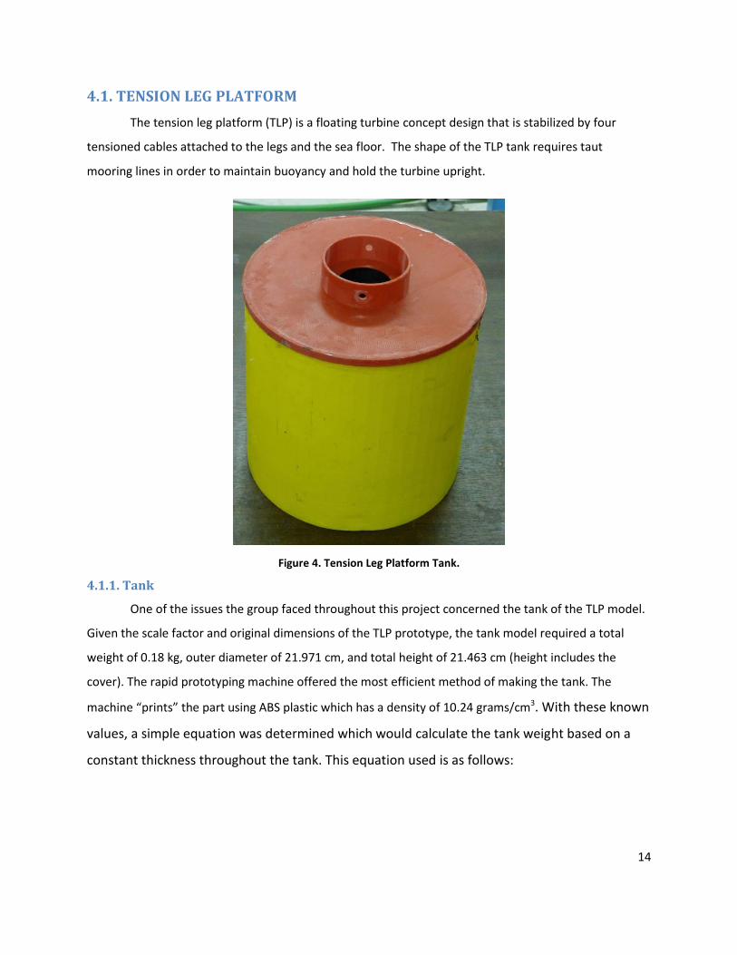
4.1. TENSION LEG PLATFORM
The tension leg platform (TLP) is a floating turbine concept design that is stabilized by four
tensioned cables attached to the legs and the sea floor. The shape of the TLP tank requires taut
mooring lines in order to maintain buoyancy and hold the turbine upright.
Figure 4. Tension Leg Platform Tank.
4.1.1. Tank
One of the issues the group faced throughout this project concerned the tank of the TLP model.
Given the scale factor and original dimensions of the TLP prototype, the tank model required a total
weight of 0.18 kg, outer diameter of 21.971 cm, and total height of 21.463 cm (height includes the
cover). The rapid prototyping machine offered the most efficient method of making the tank. The
machine “prints” the part using ABS plastic which has a density of 10.24 grams/cm3. With these known
values, a simple equation was determined which would calculate the tank weight based on a
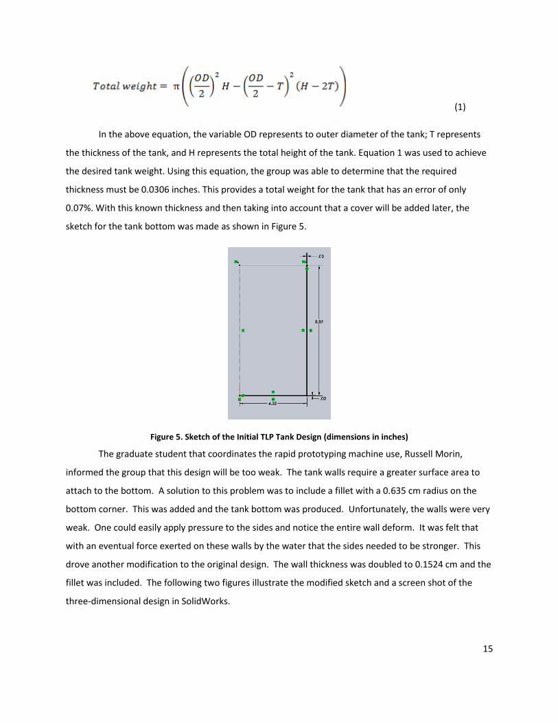
constant thickness throughout the tank. This equation used is as follows:
15
(1)
In the above equation, the variable OD represents to outer diameter of the tank; T represents
the thickness of the tank, and H represents the total height of the tank. Equation 1 was used to achieve
the desired tank weight. Using this equation, the group was able to determine that the required
thickness must be 0.0306 inches. This provides a total weight for the tank that has an error of only
0.07%. With this known thickness and then taking into account that a cover will be added later, the
sketch for the tank bottom was made as shown in Figure 5.
Figure 5. Sketch of the Initial TLP Tank Design (dimensions in inches)
The graduate student that coordinates the rapid prototyping machine use, Russell Morin,
informed the group that this design will be too weak. The tank walls require a greater surface area to
attach to the bottom. A solution to this problem was to include a fillet with a 0.635 cm radius on the
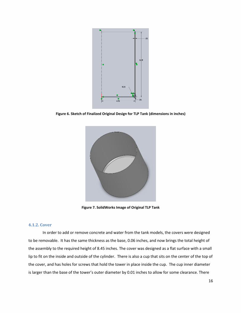
bottom corner. This was added and the tank bottom was produced. Unfortunately, the walls were very
weak. One could easily apply pressure to the sides and notice the entire wall deform. It was felt that
with an eventual force exerted on these walls by the water that the sides needed to be stronger. This
drove another modification to the original design. The wall thickness was doubled to 0.1524 cm and the
fillet was included. The following two figures illustrate the modified sketch and a screen shot of the
three-dimensional design in SolidWorks.
16
Figure 6. Sketch of Finalized Original Design for TLP Tank (dimensions in inches)
Figure 7. SolidWorks Image of Original TLP Tank
4.1.2. Cover
In order to add or remove concrete and water from the tank models, the covers were designed
to be removable. It has the same thickness as the base, 0.06 inches, and now brings the total height of
the assembly to the required height of 8.45 inches. The cover was designed as a flat surface with a small
lip to fit on the inside and outside of the cylinder. There is also a cup that sits on the center of the top of
the cover, and has holes for screws that hold the tower in place inside the cup. The cup inner diameter
is larger than the base of the tower’s outer diameter by 0.01 inches to allow for some clearance. There
17
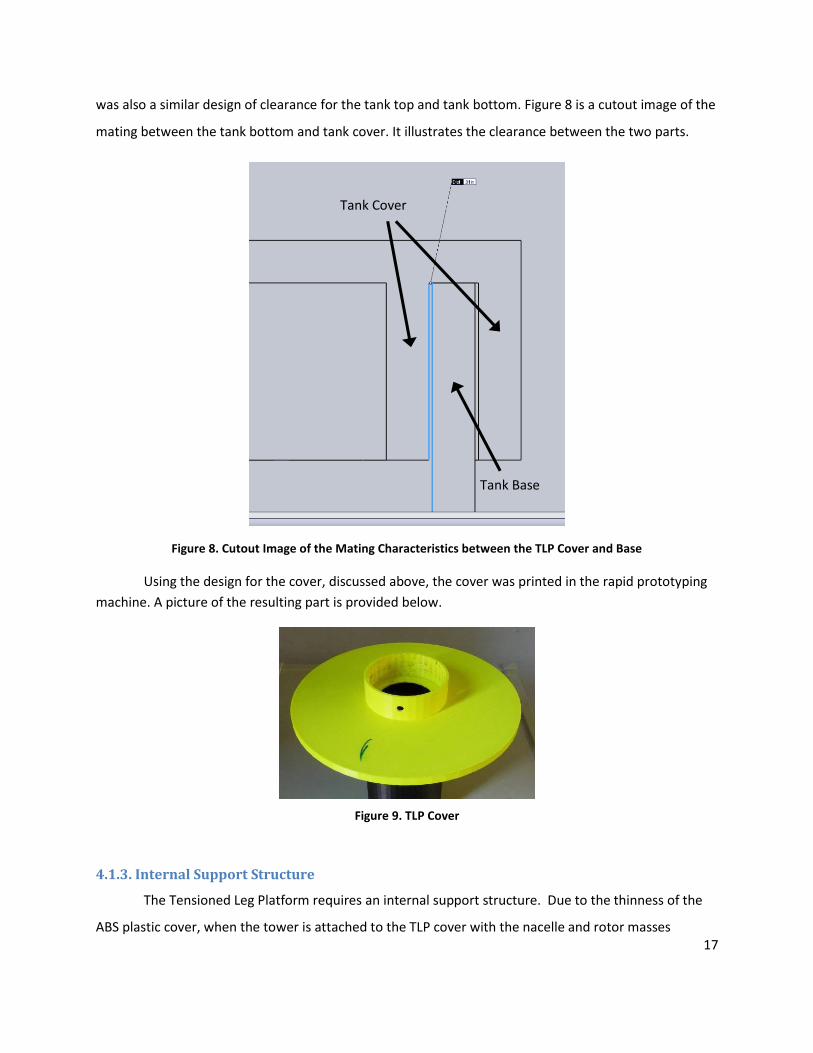
was also a similar design of clearance for the tank top and tank bottom. Figure 8 is a cutout image of the
mating between the tank bottom and tank cover. It illustrates the clearance between the two parts.
Figure 8. Cutout Image of the Mating Characteristics between the TLP Cover and Base
Using the design for the cover, discussed above, the cover was printed in the rapid prototyping
machine. A picture of the resulting part is provided below.
Figure 9. TLP Cover
4.1.3. Internal Support Structure
The Tensioned Leg Platform requires an internal support structure. Due to the thinness of the
ABS plastic cover, when the tower is attached to the TLP cover with the nacelle and rotor masses
Tank Cover
Tank Base

18
mounted at the top of the tower, slight tilting of the tower results in deflection of the TLP cover. Figure
10, below, shows this deflection.
Figure 10. TLP Cover Deflecting as a Result of Tower Movement.
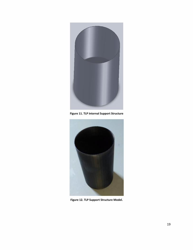
In order to reduce or eliminate these effects, a support column was built. This support column,
shown as computer model in Figure 11 and photographed in Figure 12, is a cylindrical structure which
spans the length between the top of the concrete in the TLP tank and the bottom surface of the TLP’s
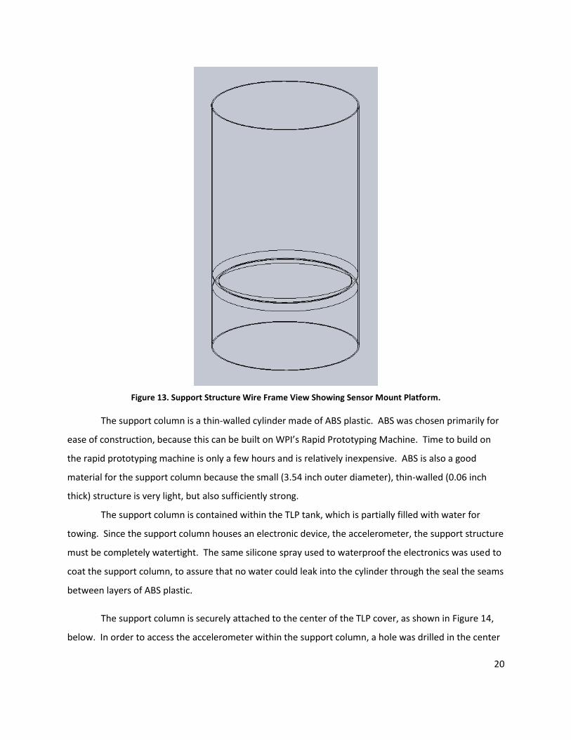
cover. This cylinder also has a platform located at the center of mass of the entire TLP structure, which
is more clearly shown in the wire-frame computer model of Figure 13. This platform is a mount for an
accelerometer, which will be used to monitor the motion of the Tensioned Leg Platform in its towing
condition during scale model tests.
19
Figure 11. TLP Internal Support Structure
Figure 12. TLP Support Structure Model.
20
Figure 13. Support Structure Wire Frame View Showing Sensor Mount Platform.
The support column is a thin-walled cylinder made of ABS plastic. ABS was chosen primarily for
ease of construction, because this can be built on WPI’s Rapid Prototyping Machine. Time to build on
the rapid prototyping machine is only a few hours and is relatively inexpensive. ABS is also a good
material for the support column because the small (3.54 inch outer diameter), thin-walled (0.06 inch
thick) structure is very light, but also sufficiently strong.
The support column is contained within the TLP tank, which is partially filled with water for
towing. Since the support column houses an electronic device, the accelerometer, the support structure
must be completely watertight. The same silicone spray used to waterproof the electronics was used to
coat the support column, to assure that no water could leak into the cylinder through the seal the seams
between layers of ABS plastic.
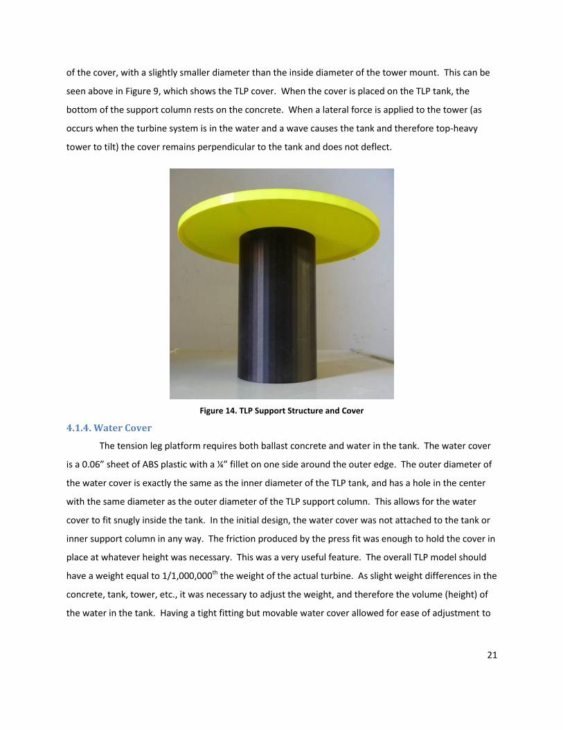
The support column is securely attached to the center of the TLP cover, as shown in Figure 14,
below. In order to access the accelerometer within the support column, a hole was drilled in the center
21
of the cover, with a slightly smaller diameter than the inside diameter of the tower mount. This can be
seen above in Figure 9, which shows the TLP cover. When the cover is placed on the TLP tank, the
bottom of the support column rests on the concrete. When a lateral force is applied to the tower (as
occurs when the turbine system is in the water and a wave causes the tank and therefore top-heavy
tower to tilt) the cover remains perpendicular to the tank and does not deflect.
Figure 14. TLP Support Structure and Cover
4.1.4. Water Cover
The tension leg platform requires both ballast concrete and water in the tank. The water cover
is a 0.06” sheet of ABS plastic with a ¼” fillet on one side around the outer edge. The outer diameter of
the water cover is exactly the same as the inner diameter of the TLP tank, and has a hole in the center
with the same diameter as the outer diameter of the TLP support column. This allows for the water
cover to fit snugly inside the tank. In the initial design, the water cover was not attached to the tank or
inner support column in any way. The friction produced by the press fit was enough to hold the cover in
place at whatever height was necessary. This was a very useful feature. The overall TLP model should
have a weight equal to 1/1,000,000th the weight of the actual turbine. As slight weight differences in the
concrete, tank, tower, etc., it was necessary to adjust the weight, and therefore the volume (height) of
the water in the tank. Having a tight fitting but movable water cover allowed for ease of adjustment to

22
achieve the desired weight. An outer diameter of 8.52 inches was used for the water cover. This
provided a clearance between it and the inner walls of the tank of 0.01 inches all around.
The primary purpose of the water cover was to prevent the water from splashing inside the TLP.
This was necessary because the displacement of weight from the water’s movement within the space
between the concrete and cover of the TLP was enough to cause the TLP to tilt greatly and become
unstable and unable to float. Figure 15 shows the SolidWorks model of this water cover.
Figure 15. SolidWorks Screenshot of Water Cover
4.2. MODIFIED VERSION OF TENSION LEG PLATFORM
As was previously mentioned, the original design of the leg assembly had unfortunately caused
the tank to list. For this reason, the legs were removed from the original TLP design; but it was believed
to be advantageous for future years’ groups to have access to a modified TLP that will incorporate a leg
design.
4.2.1. Leg Assembly
The main problem the original leg design had illustrated was that slight errors in the direction
and angles that the legs sit will cause the entire assembly to list. This problem arose because of the
difficulty of drilling accurately into concrete. After learning from the challenges associated with the first
leg design, it was determined that the legs must be assembled and attached to the tank prior to pouring
the concrete. An effort to design the assembly in such a way that would allow for easy modifications to
the actual legs was attempted. A design was proposed which had the leg structure consist of four (4)
threaded rods and a center piece acting as a connector of the four rods. A SolidWorks image of the
assembly is provided in Figure 16.
23
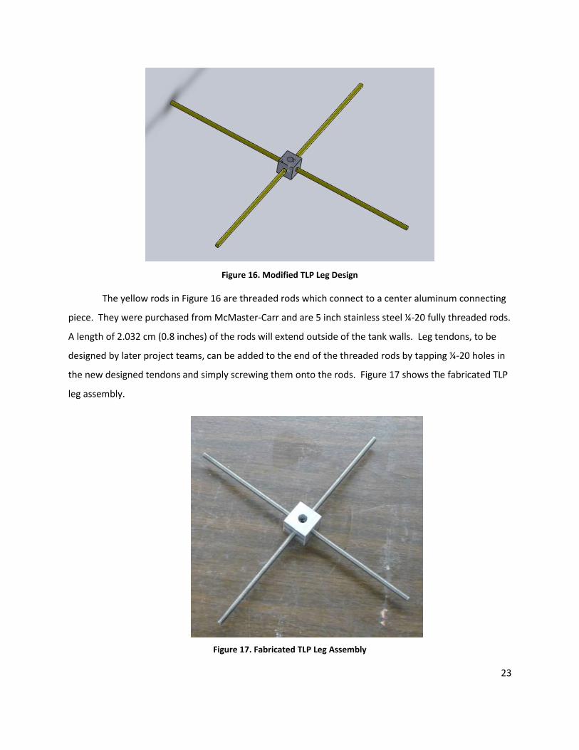
Figure 16. Modified TLP Leg Design
The yellow rods in Figure 16 are threaded rods which connect to a center aluminum connecting
piece. They were purchased from McMaster-Carr and are 5 inch stainless steel ¼-20 fully threaded rods.
A length of 2.032 cm (0.8 inches) of the rods will extend outside of the tank walls. Leg tendons, to be
designed by later project teams, can be added to the end of the threaded rods by tapping ¼-20 holes in
the new designed tendons and simply screwing them onto the rods. Figure 17 shows the fabricated TLP
leg assembly.
Figure 17. Fabricated TLP Leg Assembly

24
A connecting piece was needed to ensure that the four rods are all spaced precisely 90° apart
and level. The design for this piece required a group member to machine the part as it cannot be built
by the rapid prototyping machine. A simple picture of the mechanical drawing is shown in Figure 18.
Figure 18. Drawing of Leg Assembly Connector (dimensions in inches)
The part is a relatively simple aluminum cube with four ¼-20 taped holes around the sides and a
center hole through the top of the cube. The part was manufactured by a group member in the machine
shop, Higgins Laboratories 004. An aluminum block was machined to a 2.54 cm (1 inch) cube using the
milling machine. Then a 0.9525 cm (0.375 inch) hole was drilled in the top of the cube. This hole was
needed to center the connector piece over the center of the tank. It also allowed the assembler to view
of the four rods to ensure they all extended into the cube an equal distance. After the center hole was
drilled, four 0.51054(0.201 inch) holes were drilled into the sides of the cube. These holes were then
tapped with ¼-20 threads so that the rods can screw into the center connecting piece. It was believed
that this design will ensure that any legs, which will be attached to the rods later on, will withstand the

25
maximum potential load without breaking the tank. It also allows later groups to design different legs
that can be attached to this assembly.
4.2.2. Tank
The tank for the modified TLP had all the features and dimensions of the previous tank; but
there were several additional features added. The first additional feature was that the tank has four
holes spaced 90° apart. They were located 1.4224 cm (0.56 inches) above the base of the tank and had a
diameter of 0.635 cm (0.25 inches). These were added for the leg assembly so that the threaded rods
could extend beyond the tank wall through these holes.
Another feature which was added to the modified tank also was due to the leg assembly. In the
leg assembly the connecting piece has a 0.9525 cm (0.375) inch hole through the middle of it. This hole
had two purposes: to allow the assembler a view of the internal locations of the ends of the rods, and to
allow a method for the assembly to be centered. Because the connecting piece has a height of 1 inch
and the rods have outer diameters of 0.635 cm (0.25 inches), there is plenty of room between the
surface of the tank and the edge of the rods. A lip was added on the bottom and center of the tank. This
lip will sit in the hole running through the connector which will insure that the leg assembly is centered
within the tank.
26
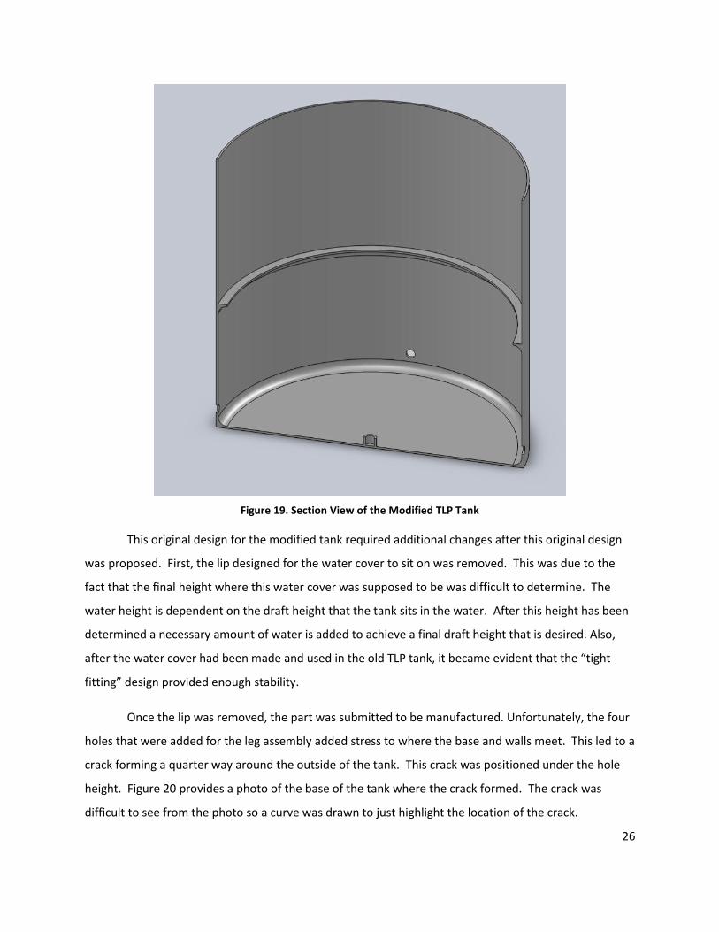
Figure 19. Section View of the Modified TLP Tank
This original design for the modified tank required additional changes after this original design
was proposed. First, the lip designed for the water cover to sit on was removed. This was due to the
fact that the final height where this water cover was supposed to be was difficult to determine. The
water height is dependent on the draft height that the tank sits in the water. After this height has been
determined a necessary amount of water is added to achieve a final draft height that is desired. Also,
after the water cover had been made and used in the old TLP tank, it became evident that the “tight-
fitting” design provided enough stability.
Once the lip was removed, the part was submitted to be manufactured. Unfortunately, the four
holes that were added for the leg assembly added stress to where the base and walls meet. This led to a
crack forming a quarter way around the outside of the tank. This crack was positioned under the hole
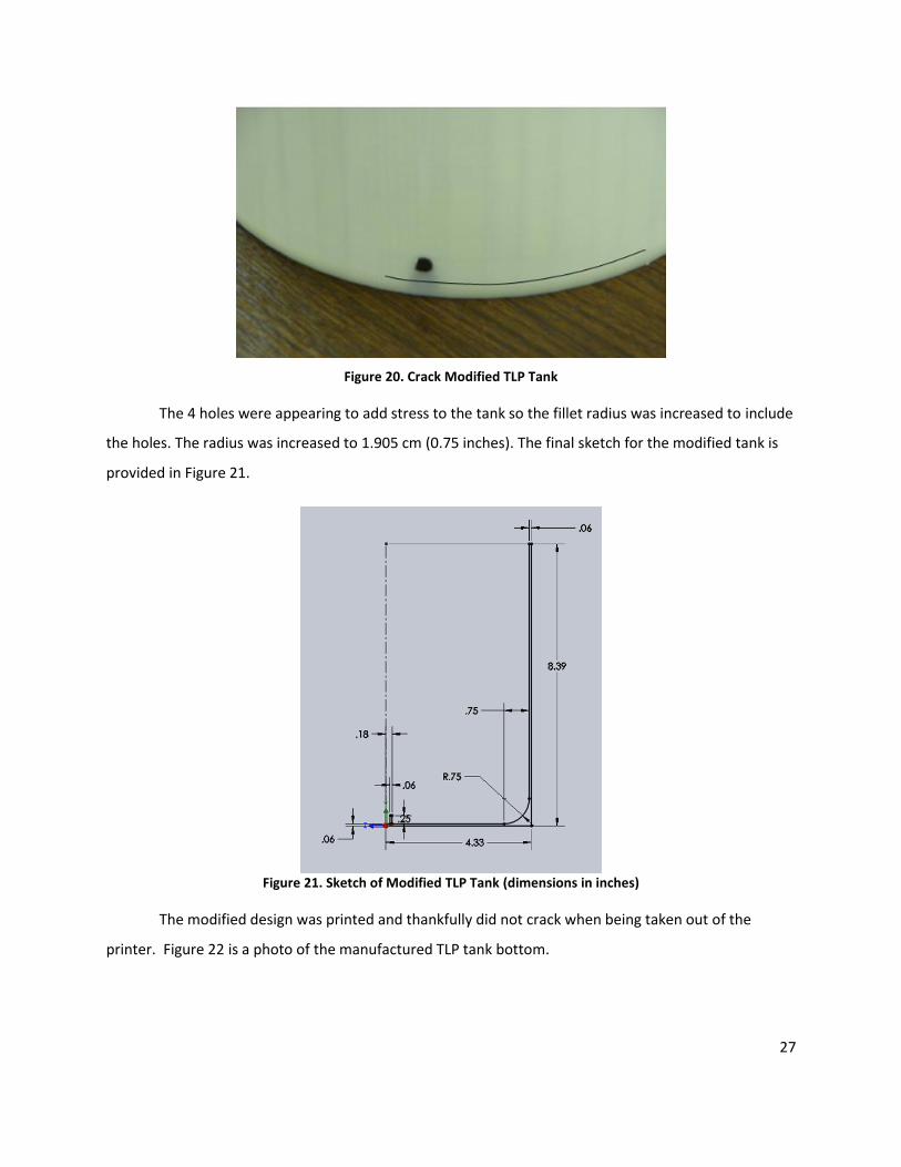
height. Figure 20 provides a photo of the base of the tank where the crack formed. The crack was
difficult to see from the photo so a curve was drawn to just highlight the location of the crack.
27
Figure 20. Crack Modified TLP Tank
The 4 holes were appearing to add stress to the tank so the fillet radius was increased to include
the holes. The radius was increased to 1.905 cm (0.75 inches). The final sketch for the modified tank is
provided in Figure 21.
Figure 21. Sketch of Modified TLP Tank (dimensions in inches)
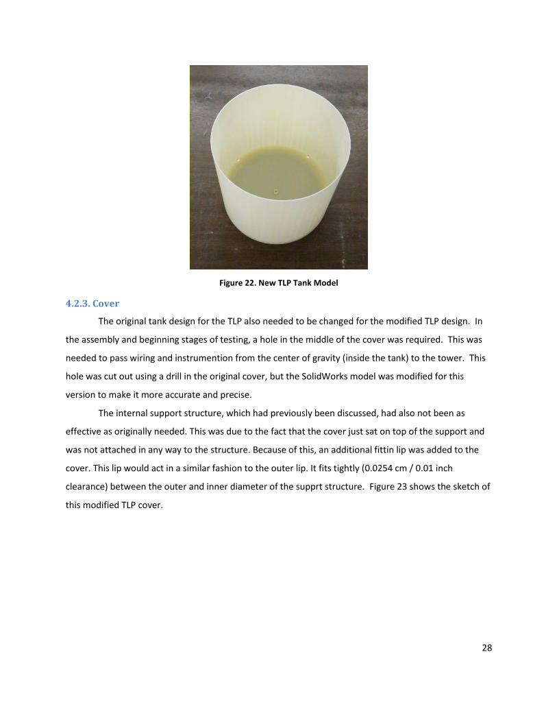
The modified design was printed and thankfully did not crack when being taken out of the
printer. Figure 22 is a photo of the manufactured TLP tank bottom.
28
Figure 22. New TLP Tank Model
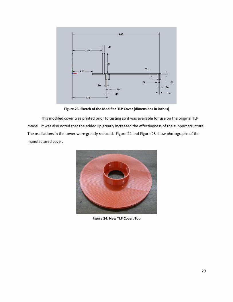
4.2.3. Cover
The original tank design for the TLP also needed to be changed for the modified TLP design. In
the assembly and beginning stages of testing, a hole in the middle of the cover was required. This was
needed to pass wiring and instrumention from the center of gravity (inside the tank) to the tower. This
hole was cut out using a drill in the original cover, but the SolidWorks model was modified for this
version to make it more accurate and precise.
The internal support structure, which had previously been discussed, had also not been as
effective as originally needed. This was due to the fact that the cover just sat on top of the support and
was not attached in any way to the structure. Because of this, an additional fittin lip was added to the
cover. This lip would act in a similar fashion to the outer lip. It fits tightly (0.0254 cm / 0.01 inch
clearance) between the outer and inner diameter of the supprt structure. Figure 23 shows the sketch of
this modified TLP cover.
29
Figure 23. Sketch of the Modified TLP Cover (dimensions in inches)
This modifed cover was printed prior to testing so it was available for use on the original TLP
model. It was also noted that the added lip greatly increased the effectiveness of the support structure.
The oscillations in the tower were greatly reduced. Figure 24 and Figure 25 show photographs of the
manufactured cover.
Figure 24. New TLP Cover, Top

30
Figure 25. New TLP Cover, Bottom
4.2.4. Complete Modified TLP
With all the components of the modified TLP model designed and manufactured, the assembly
of the complete model can be completed. Figure 26 shows the cross-section of the assembled (excluding
the water and concrete) new TLP design in SolidWorks.
Figure 26. Cross-Section of New TLP Layout
31
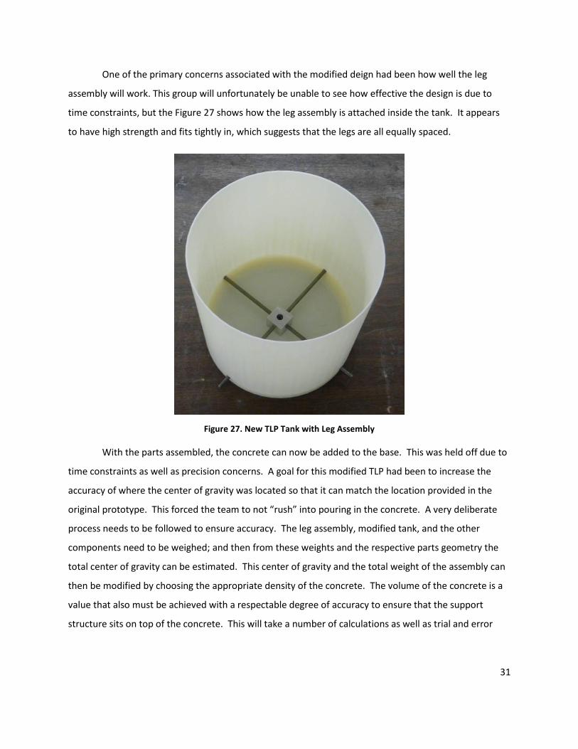
One of the primary concerns associated with the modified deign had been how well the leg
assembly will work. This group will unfortunately be unable to see how effective the design is due to
time constraints, but the Figure 27 shows how the leg assembly is attached inside the tank. It appears
to have high strength and fits tightly in, which suggests that the legs are all equally spaced.
Figure 27. New TLP Tank with Leg Assembly
With the parts assembled, the concrete can now be added to the base. This was held off due to
time constraints as well as precision concerns. A goal for this modified TLP had been to increase the
accuracy of where the center of gravity was located so that it can match the location provided in the
original prototype. This forced the team to not “rush” into pouring in the concrete. A very deliberate
process needs to be followed to ensure accuracy. The leg assembly, modified tank, and the other
components need to be weighed; and then from these weights and the respective parts geometry the
total center of gravity can be estimated. This center of gravity and the total weight of the assembly can
then be modified by choosing the appropriate density of the concrete. The volume of the concrete is a
value that also must be achieved with a respectable degree of accuracy to ensure that the support
structure sits on top of the concrete. This will take a number of calculations as well as trial and error
32
with the concrete mixture. For these reasons, adding the concrete to the modified TLP model was
delayed. Next year’s MQP project team on floating wind turbines will undertake this task.
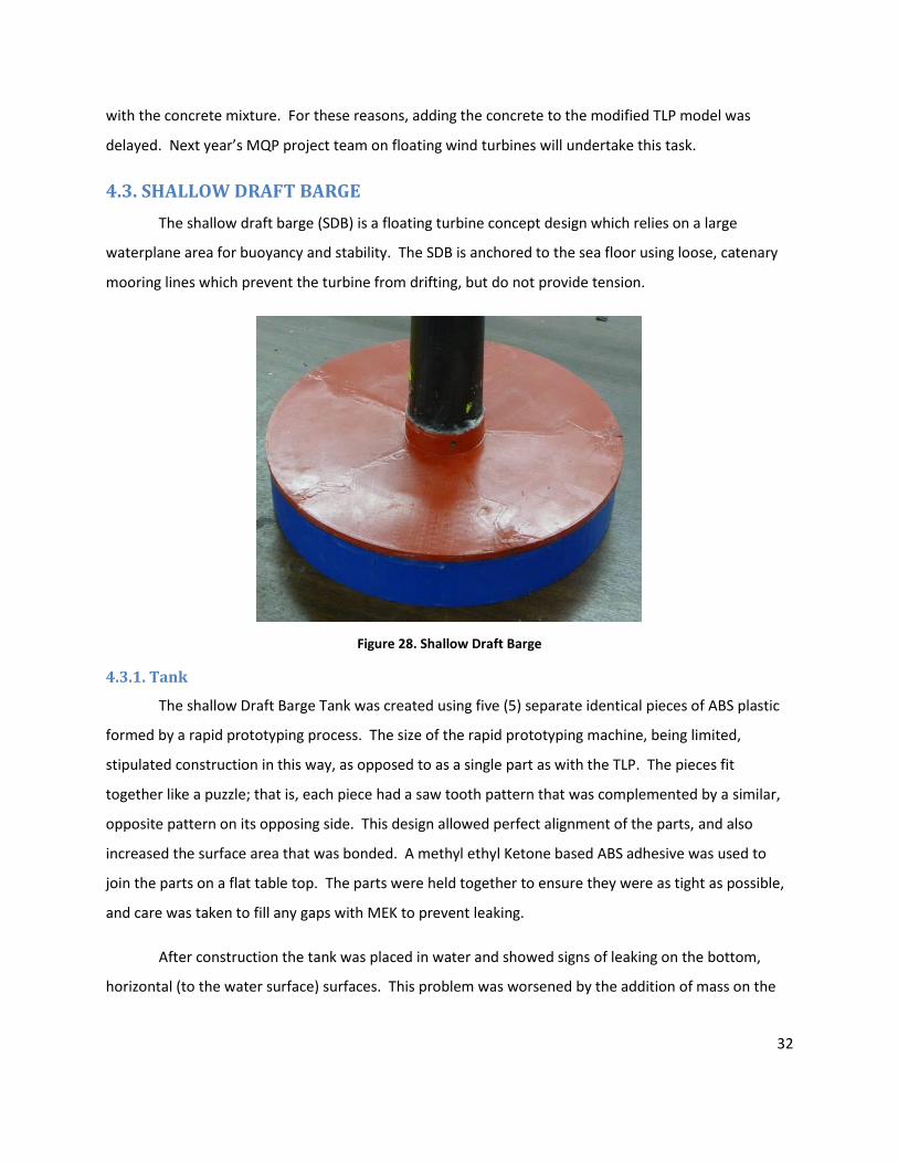
4.3. SHALLOW DRAFT BARGE
The shallow draft barge (SDB) is a floating turbine concept design which relies on a large
waterplane area for buoyancy and stability. The SDB is anchored to the sea floor using loose, catenary
mooring lines which prevent the turbine from drifting, but do not provide tension.
Figure 28. Shallow Draft Barge
4.3.1. Tank
The shallow Draft Barge Tank was created using five (5) separate identical pieces of ABS plastic
formed by a rapid prototyping process. The size of the rapid prototyping machine, being limited,
stipulated construction in this way, as opposed to as a single part as with the TLP. The pieces fit
together like a puzzle; that is, each piece had a saw tooth pattern that was complemented by a similar,
opposite pattern on its opposing side. This design allowed perfect alignment of the parts, and also
increased the surface area that was bonded. A methyl ethyl Ketone based ABS adhesive was used to
join the parts on a flat table top. The parts were held together to ensure they were as tight as possible,
and care was taken to fill any gaps with MEK to prevent leaking.
After construction the tank was placed in water and showed signs of leaking on the bottom,
horizontal (to the water surface) surfaces. This problem was worsened by the addition of mass on the
33
tank. This evidence led to the application of MEK to the bottom of the tank, to prevent water leakage
into the structure.
After completion of the tank concrete was cast into the bottom of the tank to provide a realistic
stabilization weight comparable to a possible real world application. This concrete also served to
straighten out some of the warping that occurred after the joining of the pieces into the tank, the
concrete stiffened and straightened the tank into a more robust structure.
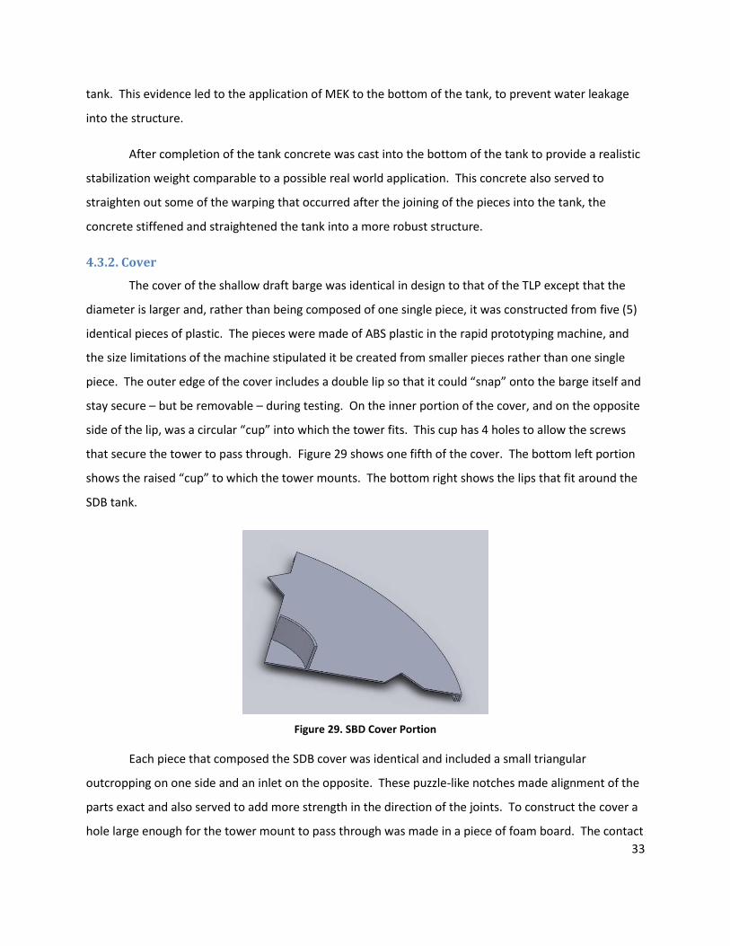
4.3.2. Cover
The cover of the shallow draft barge was identical in design to that of the TLP except that the
diameter is larger and, rather than being composed of one single piece, it was constructed from five (5)
identical pieces of plastic. The pieces were made of ABS plastic in the rapid prototyping machine, and
the size limitations of the machine stipulated it be created from smaller pieces rather than one single
piece. The outer edge of the cover includes a double lip so that it could “snap” onto the barge itself and
stay secure – but be removable – during testing. On the inner portion of the cover, and on the opposite
side of the lip, was a circular “cup” into which the tower fits. This cup has 4 holes to allow the screws
that secure the tower to pass through. Figure 29 shows one fifth of the cover. The bottom left portion
shows the raised “cup” to which the tower mounts. The bottom right shows the lips that fit around the
SDB tank.
Figure 29. SBD Cover Portion
Each piece that composed the SDB cover was identical and included a small triangular
outcropping on one side and an inlet on the opposite. These puzzle-like notches made alignment of the
parts exact and also served to add more strength in the direction of the joints. To construct the cover a
hole large enough for the tower mount to pass through was made in a piece of foam board. The contact
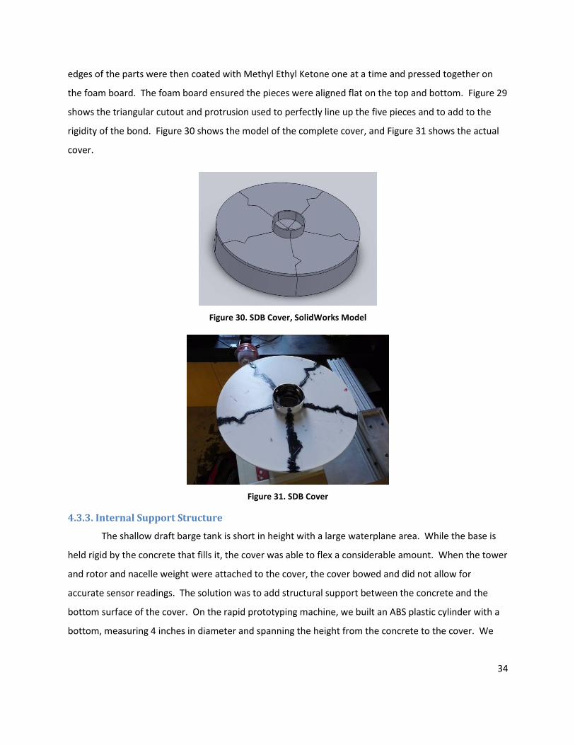
34
edges of the parts were then coated with Methyl Ethyl Ketone one at a time and pressed together on
the foam board. The foam board ensured the pieces were aligned flat on the top and bottom. Figure 29
shows the triangular cutout and protrusion used to perfectly line up the five pieces and to add to the
rigidity of the bond. Figure 30 shows the model of the complete cover, and Figure 31 shows the actual
cover.
Figure 30. SDB Cover, SolidWorks Model
Figure 31. SDB Cover
4.3.3. Internal Support Structure
The shallow draft barge tank is short in height with a large waterplane area. While the base is
held rigid by the concrete that fills it, the cover was able to flex a considerable amount. When the tower
and rotor and nacelle weight were attached to the cover, the cover bowed and did not allow for
accurate sensor readings. The solution was to add structural support between the concrete and the
bottom surface of the cover. On the rapid prototyping machine, we built an ABS plastic cylinder with a
bottom, measuring 4 inches in diameter and spanning the height from the concrete to the cover. We

35
attached the bottom of the cylinder to the bottom of the SDB cover, centered, using ABC cement.
Figure 32 and Figure 33 show the SDB cover with the first support cylinder.
Figure 32. SDB cover with support; bottom surface of cover is shown
Figure 33. SDB cover with support.
This structural support prevents the weight of the tower from bowing and flexing the cover.
Before the tower can lean, the bottom of the support cylinder touches the concrete, stopping the
motion before it can start.
Version 2 – Shallow Draft Barge Internal Support Structure.
Due to the large surface area and thinness of the cover, when the tower with full weight in the
rotor and nacelle weight was attached to the cover of the shallow draft barge, the cover flexed, even
with a four (4) inch diameter support column centered under the tower. To address this continued issue
of flexing, which interferes with the readings of the sensors at the top of the tower, we designed
another support ring that attaches to the underside of the SDB cover. This support column consists of a
1 23/32” tall, 0.03” thick cylinder with a ½” wide disc on the top and bottom. The cylinder and each disc
are attached with a ¼” fillet on either side. Figure 34 shows an image of the SolidWorks model. The
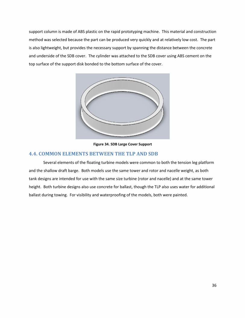
36
support column is made of ABS plastic on the rapid prototyping machine. This material and construction
method was selected because the part can be produced very quickly and at relatively low cost. The part
is also lightweight, but provides the necessary support by spanning the distance between the concrete
and underside of the SDB cover. The cylinder was attached to the SDB cover using ABS cement on the
top surface of the support disk bonded to the bottom surface of the cover.
Figure 34. SDB Large Cover Support
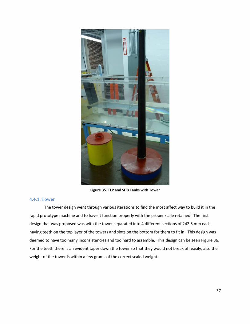
4.4. COMMON ELEMENTS BETWEEN THE TLP AND SDB
Several elements of the floating turbine models were common to both the tension leg platform
and the shallow draft barge. Both models use the same tower and rotor and nacelle weight, as both
tank designs are intended for use with the same size turbine (rotor and nacelle) and at the same tower
height. Both turbine designs also use concrete for ballast, though the TLP also uses water for additional
ballast during towing. For visibility and waterproofing of the models, both were painted.
37
Figure 35. TLP and SDB Tanks with Tower
4.4.1. Tower
The tower design went through various iterations to find the most affect way to build it in the
rapid prototype machine and to have it function properly with the proper scale retained. The first
design that was proposed was with the tower separated into 4 different sections of 242.5 mm each
having teeth on the top layer of the towers and slots on the bottom for them to fit in. This design was
deemed to have too many inconsistencies and too hard to assemble. This design can be seen Figure 36.
For the teeth there is an evident taper down the tower so that they would not break off easily, also the
weight of the tower is within a few grams of the correct scaled weight.
38
Figure 36. Tower Slot/Teeth
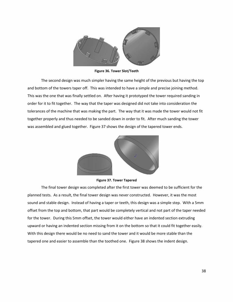
The second design was much simpler having the same height of the previous but having the top
and bottom of the towers taper off. This was intended to have a simple and precise joining method.
This was the one that was finally settled on. After having it prototyped the tower required sanding in
order for it to fit together. The way that the taper was designed did not take into consideration the
tolerances of the machine that was making the part. The way that it was made the tower would not fit
together properly and thus needed to be sanded down in order to fit. After much sanding the tower
was assembled and glued together. Figure 37 shows the design of the tapered tower ends.
Figure 37. Tower Tapered
The final tower design was completed after the first tower was deemed to be sufficient for the
planned tests. As a result, the final tower design was never constructed. However, it was the most
sound and stable design. Instead of having a taper or teeth, this design was a simple step. With a 5mm
offset from the top and bottom, that part would be completely vertical and not part of the taper needed
for the tower. During this 5mm offset, the tower would either have an indented section extruding
upward or having an indented section missing from it on the bottom so that it could fit together easily.
With this design there would be no need to sand the tower and it would be more stable than the
tapered one and easier to assemble than the toothed one. Figure 38 shows the indent design.
39
Figure 38. Tower Indent
4.4.2. Rotor and Nacelle Weight Change
In the first year of the floating turbines project, the main goal of the project was to create
models to test the movement of the TLP and SDB tank structures in the towing conditions. For
preliminary testing, the important characteristics of the model include length, weight, center of mass,
and shape for portions in contact with the water. Therefore, it is unnecessary to design a scale model of
the nacelle and rotor blades at this time. Instead, we substituted these complex mechanisms with a
container to hold sensors, an accelerometer and inclinometer, and ballast weights. The container was
weighted with brass weights from a weight set, allowing accuracy of weight and center of mass for this
portion of the wind turbine. The weight and center of mass of the rotor and nacelle portion of the
design was properly scaled to a one hundredth (1/100th) size (for a length scale of one hundredth,
weight is scaled one millionth, or 1/106).
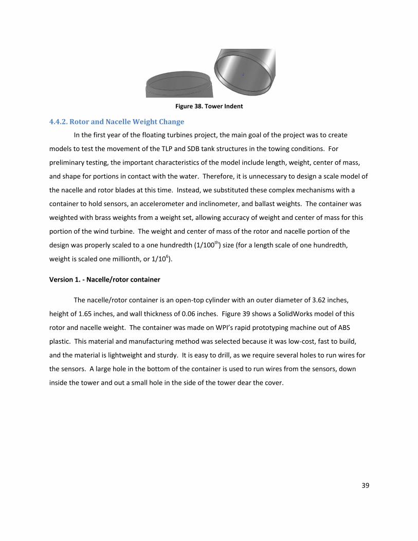
Version 1. - Nacelle/rotor container
The nacelle/rotor container is an open-top cylinder with an outer diameter of 3.62 inches,
height of 1.65 inches, and wall thickness of 0.06 inches. Figure 39 shows a SolidWorks model of this
rotor and nacelle weight. The container was made on WPI’s rapid prototyping machine out of ABS
plastic. This material and manufacturing method was selected because it was low-cost, fast to build,
and the material is lightweight and sturdy. It is easy to drill, as we require several holes to run wires for
the sensors. A large hole in the bottom of the container is used to run wires from the sensors, down
inside the tower and out a small hole in the side of the tower dear the cover.
40
Figure 39. Nacelle and Rotor Weight
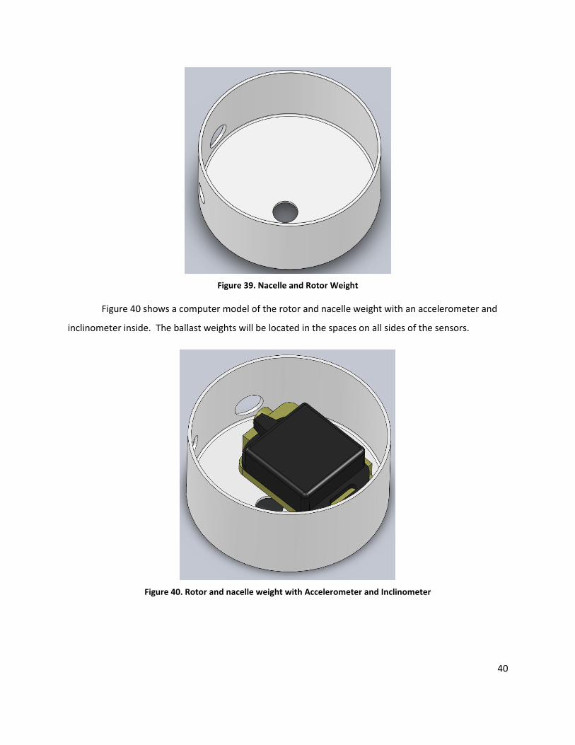
Figure 40 shows a computer model of the rotor and nacelle weight with an accelerometer and
inclinometer inside. The ballast weights will be located in the spaces on all sides of the sensors.
Figure 40. Rotor and nacelle weight with Accelerometer and Inclinometer
41
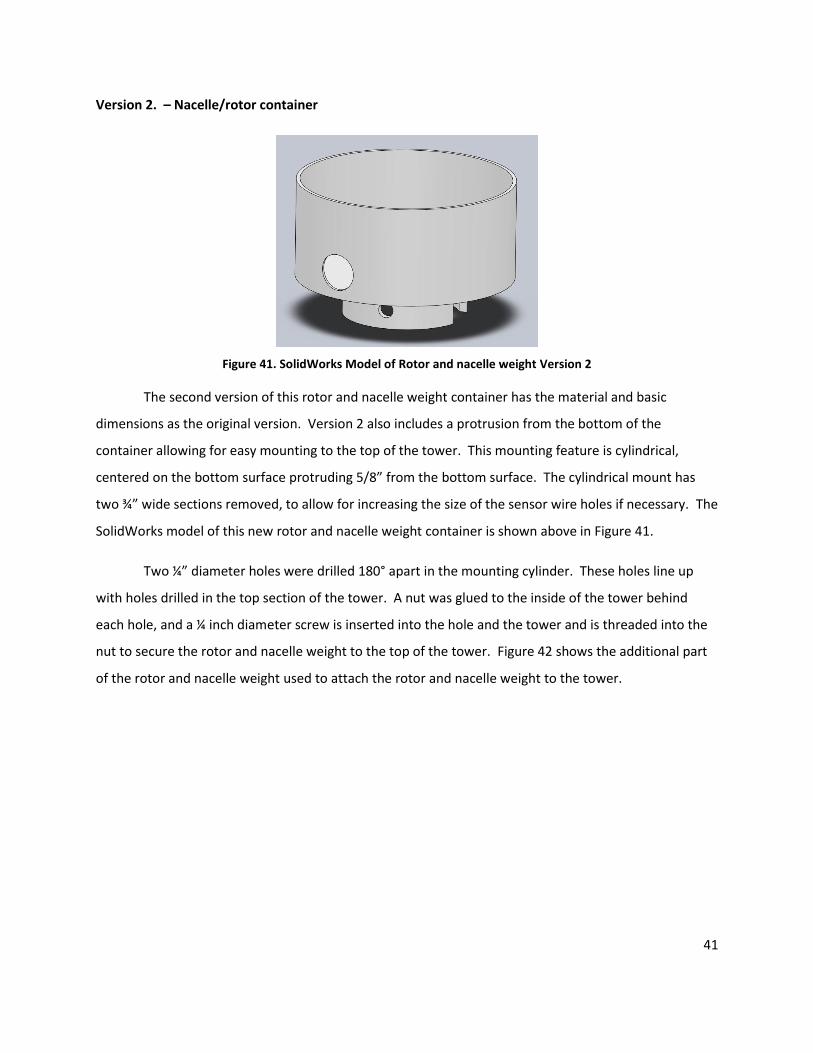
Version 2. – Nacelle/rotor container
Figure 41. SolidWorks Model of Rotor and nacelle weight Version 2
The second version of this rotor and nacelle weight container has the material and basic
dimensions as the original version. Version 2 also includes a protrusion from the bottom of the
container allowing for easy mounting to the top of the tower. This mounting feature is cylindrical,
centered on the bottom surface protruding 5/8” from the bottom surface. The cylindrical mount has
two ¾” wide sections removed, to allow for increasing the size of the sensor wire holes if necessary. The
SolidWorks model of this new rotor and nacelle weight container is shown above in Figure 41.
Two ¼” diameter holes were drilled 180° apart in the mounting cylinder. These holes line up
with holes drilled in the top section of the tower. A nut was glued to the inside of the tower behind
each hole, and a ¼ inch diameter screw is inserted into the hole and the tower and is threaded into the
nut to secure the rotor and nacelle weight to the top of the tower. Figure 42 shows the additional part
of the rotor and nacelle weight used to attach the rotor and nacelle weight to the tower.
42
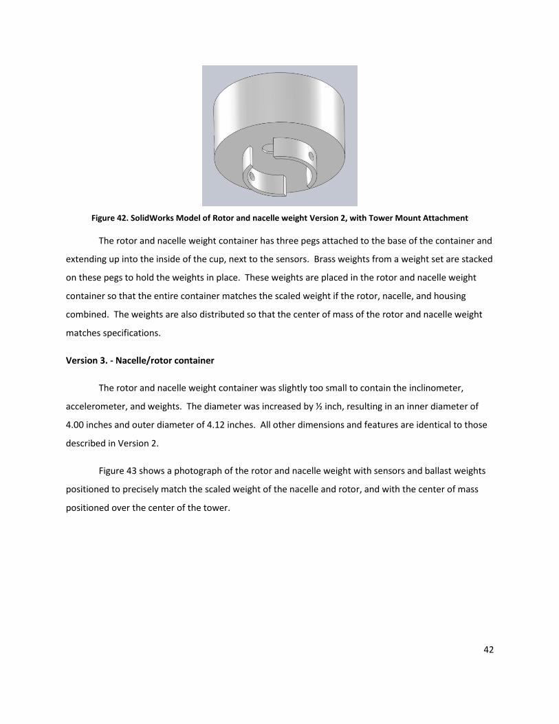
Figure 42. SolidWorks Model of Rotor and nacelle weight Version 2, with Tower Mount Attachment
The rotor and nacelle weight container has three pegs attached to the base of the container and
extending up into the inside of the cup, next to the sensors. Brass weights from a weight set are stacked
on these pegs to hold the weights in place. These weights are placed in the rotor and nacelle weight
container so that the entire container matches the scaled weight if the rotor, nacelle, and housing
combined. The weights are also distributed so that the center of mass of the rotor and nacelle weight
matches specifications.
Version 3. - Nacelle/rotor container
The rotor and nacelle weight container was slightly too small to contain the inclinometer,
accelerometer, and weights. The diameter was increased by ½ inch, resulting in an inner diameter of
4.00 inches and outer diameter of 4.12 inches. All other dimensions and features are identical to those
described in Version 2.
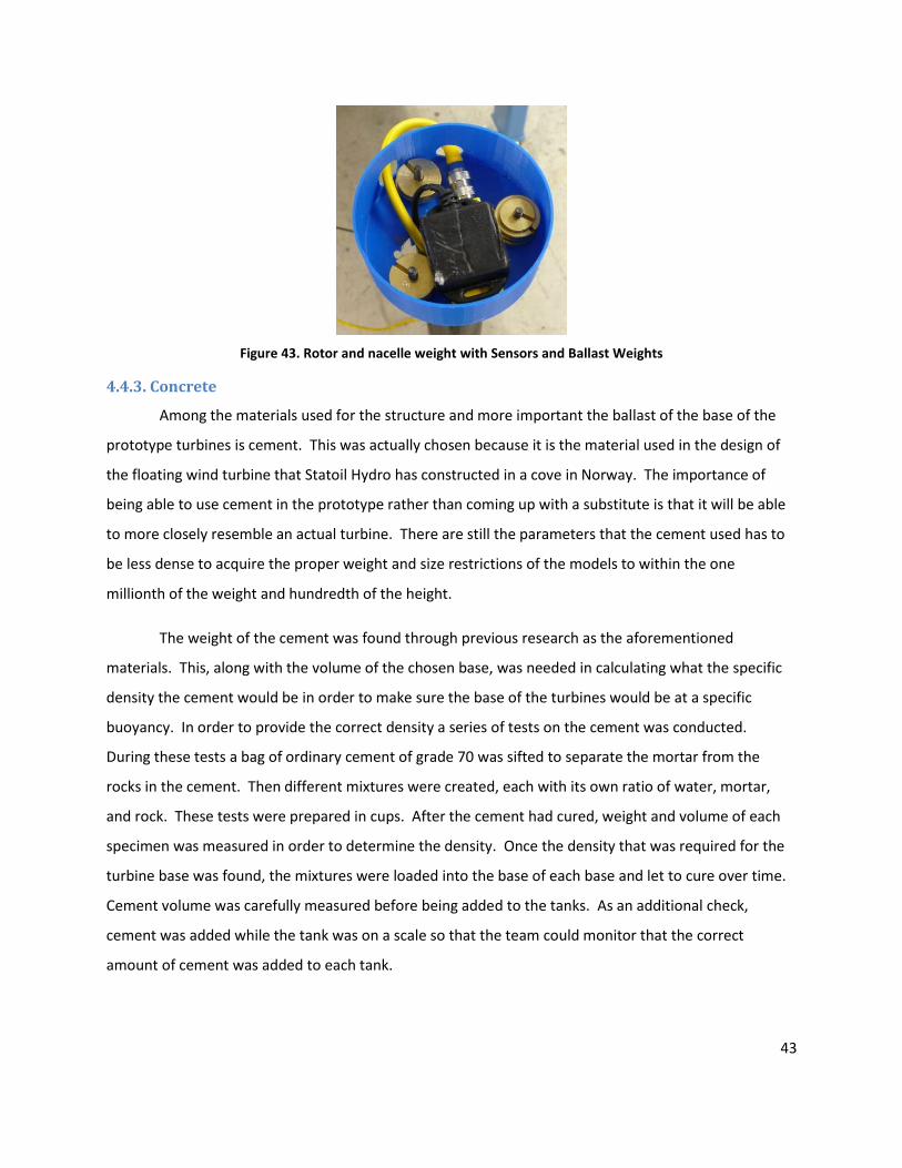
Figure 43 shows a photograph of the rotor and nacelle weight with sensors and ballast weights
positioned to precisely match the scaled weight of the nacelle and rotor, and with the center of mass
positioned over the center of the tower.
43
Figure 43. Rotor and nacelle weight with Sensors and Ballast Weights
4.4.3. Concrete
Among the materials used for the structure and more important the ballast of the base of the
prototype turbines is cement. This was actually chosen because it is the material used in the design of
the floating wind turbine that Statoil Hydro has constructed in a cove in Norway. The importance of
being able to use cement in the prototype rather than coming up with a substitute is that it will be able
to more closely resemble an actual turbine. There are still the parameters that the cement used has to
be less dense to acquire the proper weight and size restrictions of the models to within the one
millionth of the weight and hundredth of the height.
The weight of the cement was found through previous research as the aforementioned
materials. This, along with the volume of the chosen base, was needed in calculating what the specific
density the cement would be in order to make sure the base of the turbines would be at a specific
buoyancy. In order to provide the correct density a series of tests on the cement was conducted.
During these tests a bag of ordinary cement of grade 70 was sifted to separate the mortar from the
rocks in the cement. Then different mixtures were created, each with its own ratio of water, mortar,
and rock. These tests were prepared in cups. After the cement had cured, weight and volume of each
specimen was measured in order to determine the density. Once the density that was required for the
turbine base was found, the mixtures were loaded into the base of each base and let to cure over time.
Cement volume was carefully measured before being added to the tanks. As an additional check,
cement was added while the tank was on a scale so that the team could monitor that the correct
amount of cement was added to each tank.

44
4.4.4. Painting
The TLP and SDB were both painted after initial floating tests and construction. The addition of
paint to the models served two purposes; adding to the aesthetics and providing contrast to the
different components of each model for later videotaping of the experiments.
After construction, the parts of each model were different colors, and discolorations were
apparent where the MEK was used, in the case of the SDB visible joints showed, while the TLP had spots
where holes were patched. To remedy this unappealing exterior the SDB was painted blue, the TLP
yellow, and both covers red. The tower was also painted black to cover its MEK joints. This paint also
served as contrast while the tanks were being observed in testing situations. With different colors
observations of motions of various parts was easy.
45
5. TESTING
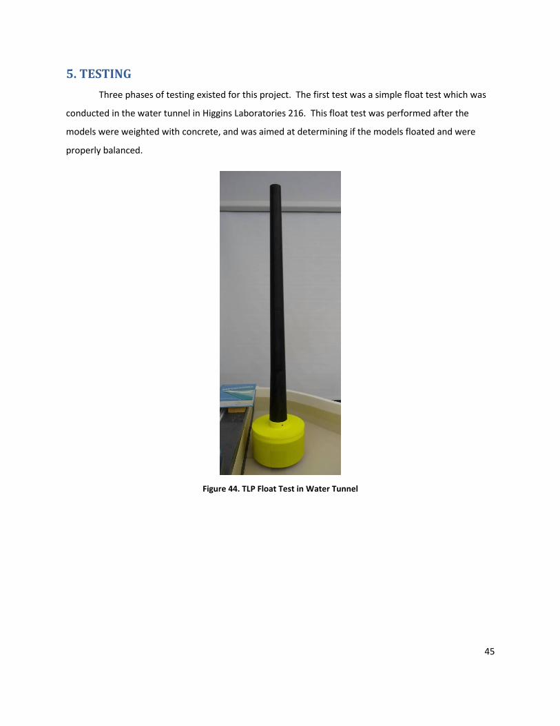
Three phases of testing existed for this project. The first test was a simple float test which was
conducted in the water tunnel in Higgins Laboratories 216. This float test was performed after the
models were weighted with concrete, and was aimed at determining if the models floated and were
properly balanced.
Figure 44. TLP Float Test in Water Tunnel
46
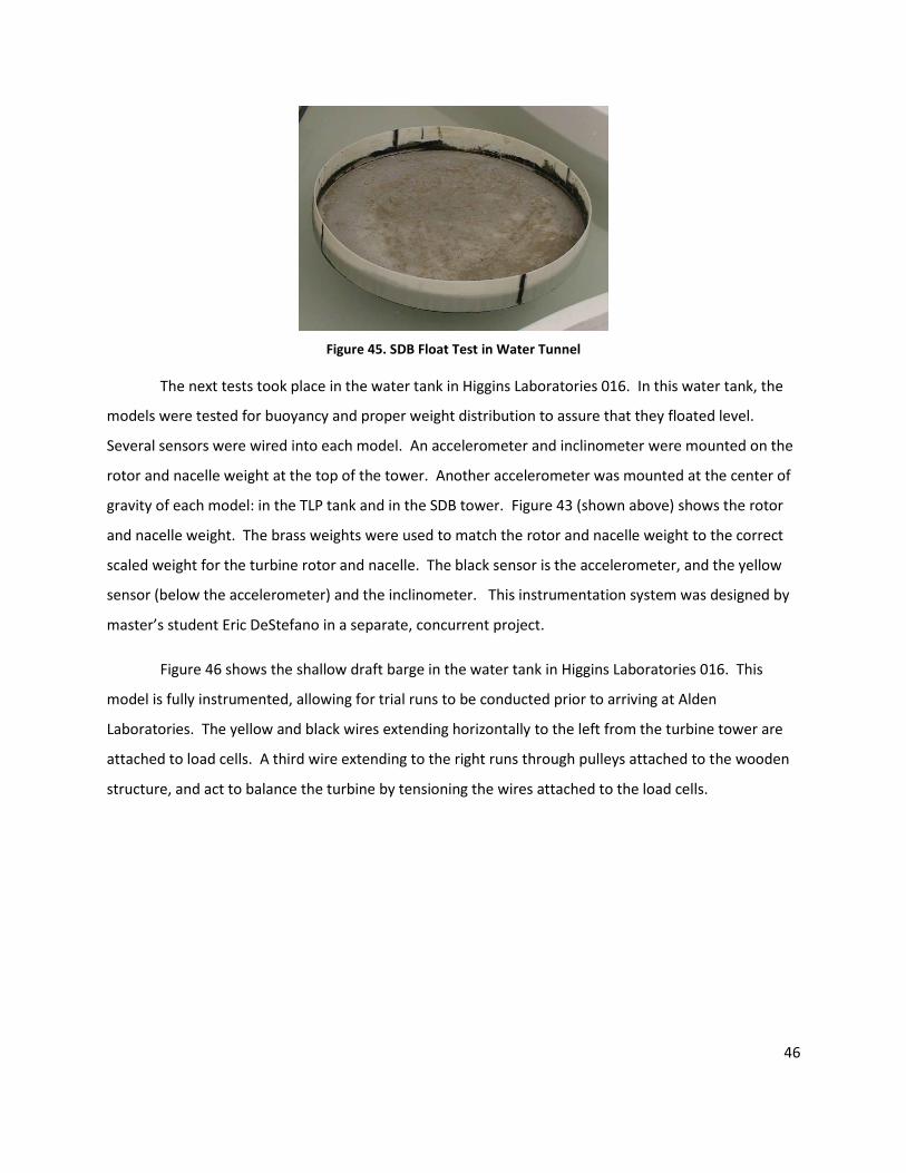
Figure 45. SDB Float Test in Water Tunnel
The next tests took place in the water tank in Higgins Laboratories 016. In this water tank, the
models were tested for buoyancy and proper weight distribution to assure that they floated level.
Several sensors were wired into each model. An accelerometer and inclinometer were mounted on the
rotor and nacelle weight at the top of the tower. Another accelerometer was mounted at the center of
gravity of each model: in the TLP tank and in the SDB tower. Figure 43 (shown above) shows the rotor
and nacelle weight. The brass weights were used to match the rotor and nacelle weight to the correct
scaled weight for the turbine rotor and nacelle. The black sensor is the accelerometer, and the yellow
sensor (below the accelerometer) and the inclinometer. This instrumentation system was designed by
master’s student Eric DeStefano in a separate, concurrent project.
Figure 46 shows the shallow draft barge in the water tank in Higgins Laboratories 016. This
model is fully instrumented, allowing for trial runs to be conducted prior to arriving at Alden
Laboratories. The yellow and black wires extending horizontally to the left from the turbine tower are
attached to load cells. A third wire extending to the right runs through pulleys attached to the wooden
structure, and act to balance the turbine by tensioning the wires attached to the load cells.
47
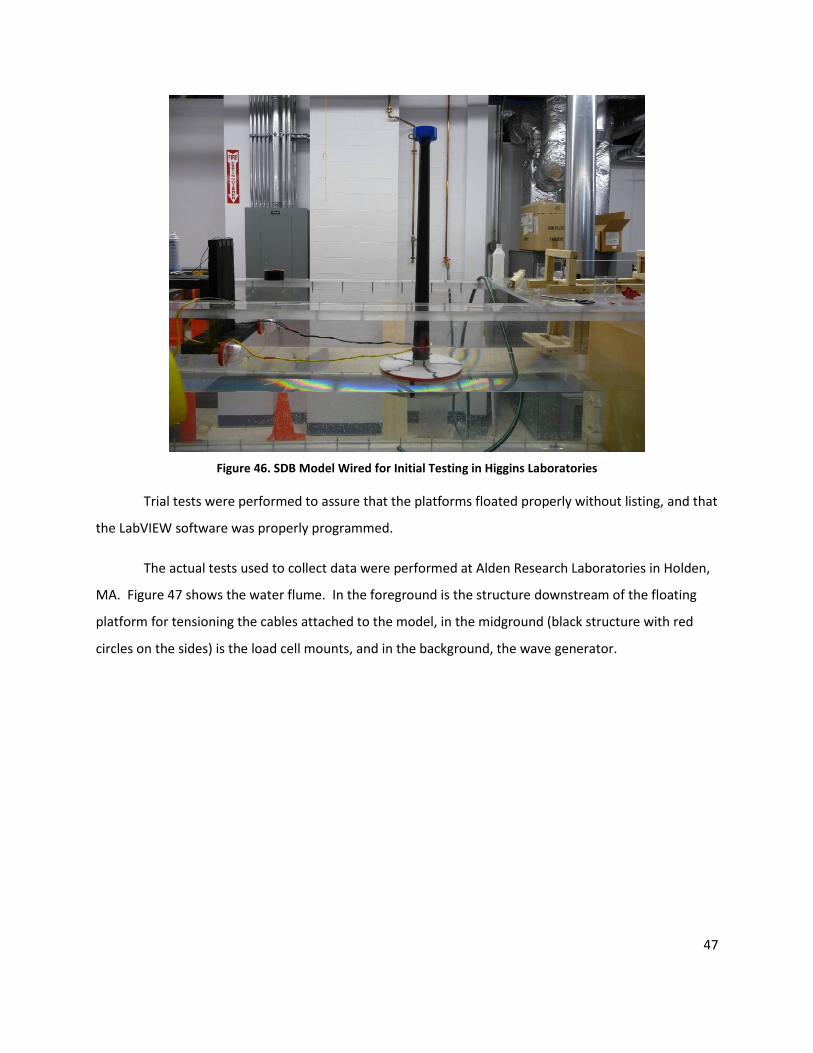
Figure 46. SDB Model Wired for Initial Testing in Higgins Laboratories
Trial tests were performed to assure that the platforms floated properly without listing, and that
the LabVIEW software was properly programmed.
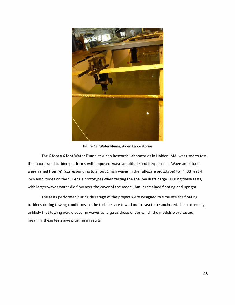
The actual tests used to collect data were performed at Alden Research Laboratories in Holden,
MA. Figure 47 shows the water flume. In the foreground is the structure downstream of the floating
platform for tensioning the cables attached to the model, in the midground (black structure with red
circles on the sides) is the load cell mounts, and in the background, the wave generator.
48
Figure 47. Water Flume, Alden Laboratories
The 6 foot x 6 foot Water Flume at Alden Research Laboratories in Holden, MA was used to test
the model wind turbine platforms with imposed wave amplitude and frequencies. Wave amplitudes
were varied from ¼” (corresponding to 2 foot 1 inch waves in the full-scale prototype) to 4” (33 feet 4
inch amplitudes on the full-scale prototype) when testing the shallow draft barge. During these tests,
with larger waves water did flow over the cover of the model, but it remained floating and upright.
The tests performed during this stage of the project were designed to simulate the floating
turbines during towing conditions, as the turbines are towed out to sea to be anchored. It is extremely
unlikely that towing would occur in waves as large as those under which the models were tested,
meaning these tests give promising results.
49
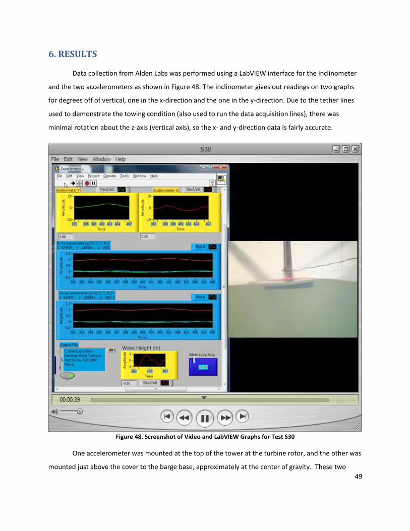
6. RESULTS
Data collection from Alden Labs was performed using a LabVIEW interface for the inclinometer
and the two accelerometers as shown in Figure 48. The inclinometer gives out readings on two graphs
for degrees off of vertical, one in the x-direction and the one in the y-direction. Due to the tether lines
used to demonstrate the towing condition (also used to run the data acquisition lines), there was
minimal rotation about the z-axis (vertical axis), so the x- and y-direction data is fairly accurate.
Figure 48. Screenshot of Video and LabVIEW Graphs for Test S30
One accelerometer was mounted at the top of the tower at the turbine rotor, and the other was
mounted just above the cover to the barge base, approximately at the center of gravity. These two

50
measured acceleration in the x-, y-, and z-directions. The x- and y- directions had minimal accelerations
recorded due to the fairly taut tether lines. The z-direction accelerometer however, felt the rise and fall
of the model as it was carried vertically by the waves. This line is colored red on the graphs and was
centered on at 1 on the Y-axis of the graph. The variation about the center line (1 for the z-direction
acceleration) indicates the number of g’s (number of times the acceleration of gravity) experienced by
the model at a given point in time. For test S30 seen in Figure 48 the maximum acceleration felt by the
model in the z-direction is approximately ±.025g ≈ 2.45 m/s2.
The final piece of equipment used and recorded with LabVIEW was a wave height gauge. This
device was provided by Alden Research Labs, and used a small buoyant ball on a thin metal rod that
went through a rotating joint on a potentiometer to measure wave height based on the amount of
rotation experienced by the joint. As the water height caused the ball to rise and fall the joint rotation
was measured on the yellow graph at the bottom of the test page. For test S30 there appears to be a
rise and fall of just over ±1 inch from the neutral point, or a net displacement of just over 2 inches.
The shallow draft barge was initially tested with over 45 test runs, with a variety of different
wave heights and frequencies. Due to some issues with the stability of the tension leg platform, testing
on this model was pushed to the end the available test time. Each test was run for about 90 seconds
and a side view video was taken as seen in Figure 48 as well as top view video filmed from above.
Additionally, for each test all of the data was output to Excel files for further analysis. Detailed data was
measured for degree of inclination in two directions, acceleration in three directions from two location,
and measured wave height all versus time. In future analysis of this data will be extrapolated to the full-
scale prototype wind turbine platforms, and used to prove the overall viability of the floating wind
turbine concept, as well as the strengths and weaknesses of each model concept. Furthermore,
suggestions for design improvements may be made.
51
7. CONCLUSIONS
The limited supply of fossil fuels and the desire to reduce the amount of greenhouse gases
produced are two of the best arguments for using renewable energy sources. Wind power stands to gain
a significant increase in potential power production by moving the location of the turbine to one with
much greater wind speeds. The site with the most promise at this time is the ocean. Floating wind
turbines are an emerging renewable energy concept that may play a significant role in meeting future
energy needs.
This report has examined current full-scale deep sea floating wind turbine designs. Scale models
(100:1 scale) of two potential floating wind turbine platform concepts were designed and built. The
models were equipped with inclinometers and accelerometers and were tested in several facilities,
including in a flume with a wave generator at Alden Research Labs in Holden, MA. While the tension leg
platform design had some stability problems in the initial design, a significant amount of data was
collected from the tests run on the shallow draft barge models. The tests run on the barge simulated
conditions from calm water to the equivalent of a very strong storm, and based on our test situations
the model stayed afloat and was very well balanced.
A good deal of further testing is still needed in the future. Improvements should be made to
both models, and the new TLP design should be tested. Future work is discussed in the following
section.

52
8. FUTURE WORK
While much progress was made in the first stage of this project, work remains to be done before
conclusions regarding the optimal design of floating wind turbine platforms can be made. As the models
have gone through numerous tests and modifications, the models should be rebuilt on the rapid
prototyping machine and can be assembled following the procedure outlined in the Design and
Manufacture section of this report. The TLP has been recently redesigned and built, but any further
changes or alterations should be considered before moving forward with the project. These may include
adding legs to the structure that simulate the actual tendon/tether connections. Tests should be
performed in the Alden Water Flume, where wave frequency and amplitude can be controlled. The TLP
must be tested under both towing and operating conditions, and the SDB must be tested under
operating conditions.
Objectives
Attempt to determine maximum platform amplitudes and resonant conditions under wave
loading
Integrate instrumentation into models to monitor turbine motion, including platform and tower
frequencies and amplitudes, platform and tower pitch and heave motions, mooring line
tensions, and wave frequencies and amplitudes while turbine is in operating condition
Continue experiments in Alden Flume, where wave frequencies and amplitudes can be more
accurately produced
Compare model test results from the Alden Flume to numerical simulations and analyze both
sets of results
Determine whether tensioned tethers (used on the tension leg platform) or catenary moorings
(used on the shallow draft barge) are most suitable under various conditions
Determine the optimal platform (tension leg platform or shallow draft barge) for various wind
conditions, wave heights, turbine sizes, and ocean depths
53
The main goal of this year’s project was testing under towing conditions; however, in the future
testing of the models under simulated operating conditions is suggested. Slight modification of the
models would be needed to accomplish this. Legs (tendons) should be designed for the second TLP
made this year that can attach to the provided threaded rods on the model. The TLP can then be
tested in towing conditions with legs, as well as in the operational configuration. This operational
configuration may include a plate sunk to the bottom of the flume with provisions for attachment of
the actual tension members that would be attached to the legs of the TLP. Testing the SDB under
actual operational conditions can also be accomplished in the future. An SDB with points for the
attachment of simulated staying cables can be created, or the current model can be modified.
In testing for the towing conditions, cables for data transfer were run along the cables used to
keep the models in place. While these cables did not interfere with the testing under towing
conditions, a wireless data transfer system may be of interest for future tests. With this addition the
interference of cables will be eliminated and a more accurate set of data could be obtained not only
for towing conditions, but especially for operating conditions.
54
REFERENCES 1. “Renewable Energy Consumption in the Nation’s Energy Supply.” Energy Information Administration. URL: http://www.eia.doe.gov/cneaf/alternate/page/renew_energy_consump/figure1.html [Cited 7 March 2010]
2. “United States 50-Meter Wind Resource Map.” US Department of Energy. URL: http://www.windpoweringamerica.gov/ [Cited 7 March 2010]
3. “20% Wind Energy by 2030” American Wind Energy Association. URL: http://www.awea.org/publications/reports/AWEA20percentReportCard09.pdf [Cited 6 March 2010]
4. Pasqualetti, M. J., “Morality, space, and the power of wind-energy landscapes,” Geographical Review, Vol. 90, No. 3, July 2000, pp.381-394.
5. “Wind Energy and the Environment,” American Wind Energy Association, URL: http://www.awea.org/faq/wwt_environment.html [cited 9 October 2008];
6. “Wind Power,” Northeast Sustainable Energy Association, 2001, URL: http://www.nesea.org/energy/info/wind.html [cited 9 October 2009]
7. Butterfield, S., Musial, W., Jonkman, J., & Sclavounos, P., “Engineering Challenges for Floating Offshore Wind Turbines,” Proceedings of the 2005 Copenhagen Offshore Wind Conference, NREL/CP-500-38776, 2005.
8. Anscombe, N., “Turbines Take Float,” IEEE Power Engineer, Vol. 18, No. 6, 2004.
9. Rosner, Hillary, “Wind Power: Turbines take root in the sea,” Popular Science July 2009.
10. Heronemus, W.E., “Power from offshore winds,” 8th
Annual Conference and Exposition on Applications of Marine Technology to Human Needs, 435-466, 1972. – p. 436
11. Jonkman, J.M. & Buhl, M.L., National Renewable Energy Laboratory, “Development and Verification of a Fully Coupled
Simulator for Offshore Wind Turbines”, Proc. Of the 45th AIAA Aerospace Sciences Meeting, Vol. 4, 2510-2534, (2007)
12. S. Butterfield, A. Boone and W. Musial, “Feasibility of Floating Platform Systems for Wind Turbines.” National Renewable Energy Laboratory, Preprint to be presented at the 23rd ASME Wind Energy Symposium, (November 2003) NREL/CP-500-34874
13. “StatoilHydro to build first full scale offshore floating wind turbine,” StatoilHydro, 22 May 2008, URL: http://www.statoilhydro.com/en/NewsAndMedia/News/2008/Pages/hywind_fullscale.aspx [cited 24 October 2009]
14. “Power line in place,” StatoilHydro, 11 August 2009, URL: http://www.statoilhydro.com/en/NewsAndMedia/News/2009/Pages/11AugHywind.aspx [cited 24 October 2009]
15. Butterfield, S., Musial, W., Jonkman, J., Sclavounos, P., & Wayman, E.N. “Coupled Dynamic Modeling of Floating Wind Turbine Systems,” Proceedings of the Offshore Technology Conference, NREL/CP-500-39481, Houston, Texas, 2006.
16. Wayman, E., Massachusetts Institute of Technology, “Coupled Dynamics and Economic Analysis of Floating Wind Turbine
Systems,” June 2006.
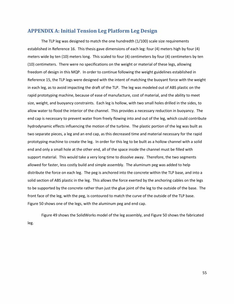
55
APPENDIX A: Initial Tension Leg Platform Leg Design
The TLP leg was designed to match the one hundredth (1/100) scale size requirements
established in Reference 16. This thesis gave dimensions of each leg: four (4) meters high by four (4)
meters wide by ten (10) meters long. This scaled to four (4) centimeters by four (4) centimeters by ten
(10) centimeters. There were no specifications on the weight or material of these legs, allowing
freedom of design in this MQP. In order to continue following the weight guidelines established in
Reference 15, the TLP legs were designed with the intent of matching the buoyant force with the weight
in each leg, as to avoid impacting the draft of the TLP. The leg was modeled out of ABS plastic on the
rapid prototyping machine, because of ease of manufacture, cost of material, and the ability to meet
size, weight, and buoyancy constraints. Each leg is hollow, with two small holes drilled in the sides, to
allow water to flood the interior of the channel. This provides a necessary reduction in buoyancy. The
end cap is necessary to prevent water from freely flowing into and out of the leg, which could contribute
hydrodynamic effects influencing the motion of the turbine. The plastic portion of the leg was built as
two separate pieces, a leg and an end cap, as this decreased time and material necessary for the rapid
prototyping machine to create the leg. In order for this leg to be built as a hollow channel with a solid
end and only a small hole at the other end, all of the space inside the channel must be filled with
support material. This would take a very long time to dissolve away. Therefore, the two segments
allowed for faster, less costly build and simple assembly. The aluminum peg was added to help
distribute the force on each leg. The peg is anchored into the concrete within the TLP base, and into a
solid section of ABS plastic in the leg. This allows the force exerted by the anchoring cables on the legs
to be supported by the concrete rather than just the glue joint of the leg to the outside of the base. The
front face of the leg, with the peg, is contoured to match the curve of the outside of the TLP base.
Figure 50 shows one of the legs, with the aluminum peg and end cap.
Figure 49 shows the SolidWorks model of the leg assembly, and Figure 50 shows the fabricated
leg.
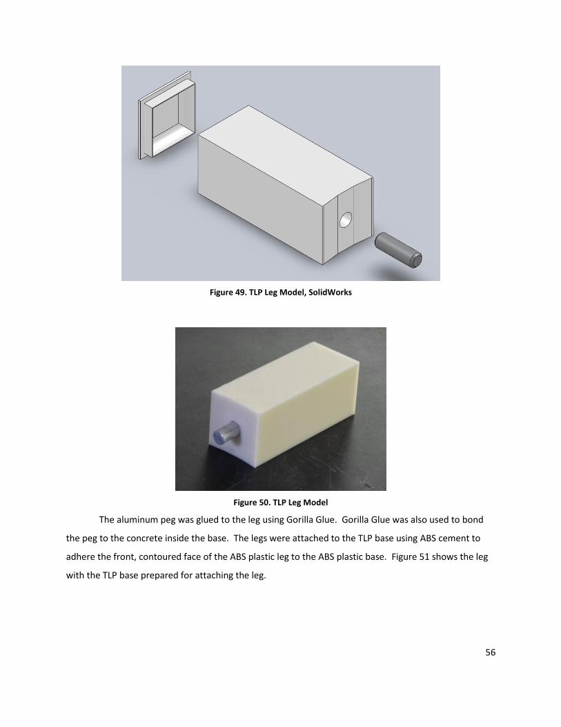
56
Figure 49. TLP Leg Model, SolidWorks
Figure 50. TLP Leg Model
The aluminum peg was glued to the leg using Gorilla Glue. Gorilla Glue was also used to bond
the peg to the concrete inside the base. The legs were attached to the TLP base using ABS cement to
adhere the front, contoured face of the ABS plastic leg to the ABS plastic base. Figure 51 shows the leg
with the TLP base prepared for attaching the leg.
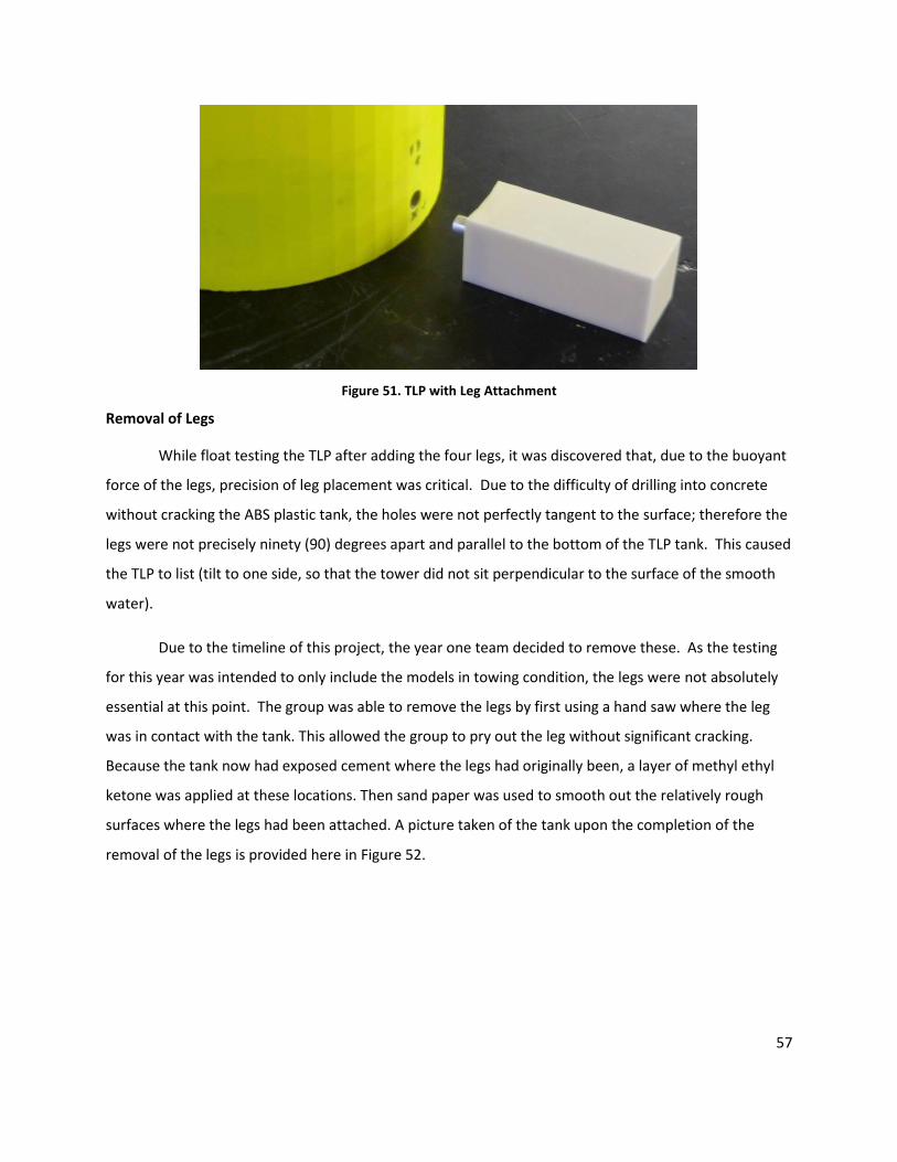
57
Figure 51. TLP with Leg Attachment
Removal of Legs
While float testing the TLP after adding the four legs, it was discovered that, due to the buoyant
force of the legs, precision of leg placement was critical. Due to the difficulty of drilling into concrete
without cracking the ABS plastic tank, the holes were not perfectly tangent to the surface; therefore the
legs were not precisely ninety (90) degrees apart and parallel to the bottom of the TLP tank. This caused
the TLP to list (tilt to one side, so that the tower did not sit perpendicular to the surface of the smooth
water).
Due to the timeline of this project, the year one team decided to remove these. As the testing
for this year was intended to only include the models in towing condition, the legs were not absolutely
essential at this point. The group was able to remove the legs by first using a hand saw where the leg
was in contact with the tank. This allowed the group to pry out the leg without significant cracking.
Because the tank now had exposed cement where the legs had originally been, a layer of methyl ethyl
ketone was applied at these locations. Then sand paper was used to smooth out the relatively rough
surfaces where the legs had been attached. A picture taken of the tank upon the completion of the
removal of the legs is provided here in Figure 52.
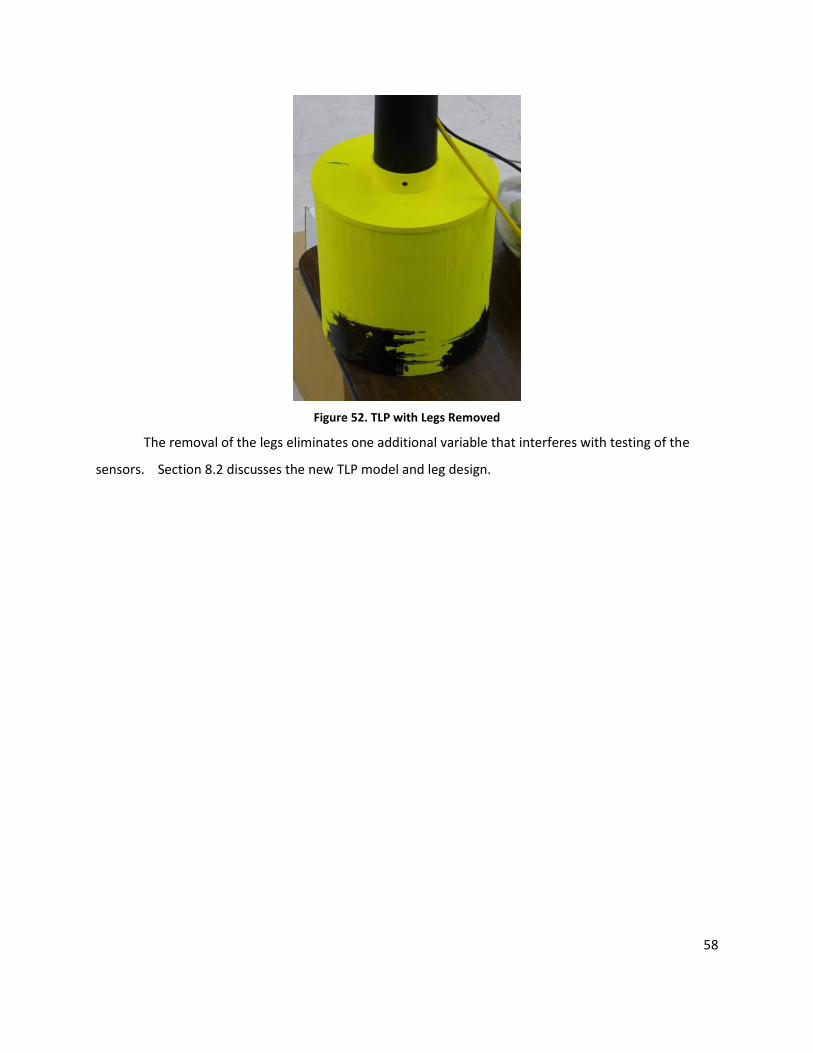
58
Figure 52. TLP with Legs Removed
The removal of the legs eliminates one additional variable that interferes with testing of the
sensors. Section 8.2 discusses the new TLP model and leg design.