march 2000 s.p.a. - gasboilerforums flueing options.pdf · the modena 80, modena 102, domina 80,...
TRANSCRIPT

S.p.A.
FLUE SYSTEMSMANUAL FOR ROOM SEALEDBOILERS
March 2000
S.p.A.
Férroli Limited, Stockton Close, Minworth Industrial Park,Minworth, Sutton Coldfield, West Midlands, B76 1DHTel: 0121 352 3500 Fax: 0121 352 3210Technical Helpline: 0121 352 3200
Férroli pursues a policy of continuous product improvement and reservesthe right to alter specifications and design without prior notice.
23??? férroli flue bro Feb 18/2/00 1:23 pm Page 1 (1,1)

- 1 -
INDEX
1. Boiler connections and dimensional drawings• Domina 80 . . . . . . . . . . . . . . . . . . . . . . . . . . . . . . . . . . . . . . . page 2• Modena 80 . . . . . . . . . . . . . . . . . . . . . . . . . . . . . . . . . . . . . . . page 3• Modena 102 . . . . . . . . . . . . . . . . . . . . . . . . . . . . . . . . . . . . . . page 4• Sigma 30-40-50-60 . . . . . . . . . . . . . . . . . . . . . . . . . . . . . . . . . page 5• Tempra . . . . . . . . . . . . . . . . . . . . . . . . . . . . . . . . . . . . . . . . . . page 6• Talent . . . . . . . . . . . . . . . . . . . . . . . . . . . . . . . . . . . . . . . . . . . page 7
2. Flue systems• General flue connection notices and terminal position . . . . . . . page 8-9
2.1 Concentric flue systems• Determining maximum flue length permissible . . . . . . . . . . . . page 10• Examples of boiler installation with concentric system . . . . . . page 11-12
2.2 Two pipe flue system• Determining maximum flue length permissible . . . . . . . . . . . . page 13-14• Examples of boiler installation with 2 pipe system . . . . . . . . . page 15-18
2.3 Collective flue systems• Minimum cross sections for flue gas evacuation pipes
for collective systems . . . . . . . . . . . . . . . . . . . . . . . . . . . . . . page 19• Examples of connections with collective systems. . . . . . . . . . page 20
3. Accessories for flue systems• Accessories for concentric systems . . . . . . . . . . . . . . . . . . . . page 21-24• Accessories for two pipe systems . . . . . . . . . . . . . . . . . . . . . page 25-27
Férroli pursues a policy of continuous product improvement and reservesthe right to alter specifications and design without prior notice.
23??? férroli flue bro Feb 18/2/00 1:23 pm Page 3 (1,1)

Férroli pursues a policy of continuous product improvement and reservesthe right to alter specifications and design without prior notice.
Modena 80
Key1 22 mm central heating flow outlet2 15 mm domestic hot water flow outlet3 15 mm gas inlet - supply to be a minimum of 22mm4 15 mm domestic cold water inlet5 22 mm central heating return inlet
1 2 3 4 5
15012012070
110
80 8080
460
Boiler cover
1149560609536
100
720
725
16025
10
100270
460
175100
Boiler connections
Dis
tanc
e be
twee
n co
nnec
tions
Distancebetweenconnections
95
60 120280
- 3 -- 2 -
Domina 80
1. Boiler connections and dimensional drawings
Key1 22 mm central heating flow outlet2 15 mm domestic hot water flow outlet3 15 mm gas inlet - supply to be a minimum of 22mm4 15 mm domestic cold water inlet5 22 mm central heating return inlet
1 2 3 4 5
15012012070
110
80 8080
460
Boiler cover
1149560609536
100
720
725
16025
10
100270
460
175100
178
190 270
Boiler connections
Dis
tanc
e be
twee
n co
nnec
tions
Distancebetweenconnections
95
Férroli pursues a policy of continuous product improvement and reservesthe right to alter specifications and design without prior notice.
S.p.A. S.p.A.S.p.A.
23??? férroli flue bro Feb 18/2/00 1:23 pm Page 5 (1,1)

Férroli pursues a policy of continuous product improvement and reservesthe right to alter specifications and design without prior notice.
25
A
25
B C
147
15
50
120 50
F
E
D
50
200
21
Front view
Right side view
220
Top view
3
4
600
620
Model
Sigma 30-40
Sigma 50-60
Amm
320
400
Bmm
53
70
Cmm
85
150
Dmm
132
130
Emm
35
30
Fmm
60
55
Sigma
Key1 Ø 22 mm flow outlet2 Ø 22 mm return3 Ø 15 mm gas inlet - supply to be a minimum of 22mm4 Rear air inlet/flue outlet
- 5 -Férroli pursues a policy of continuous product improvement and reservesthe right to alter specifications and design without prior notice.
Modena 102
- 4 -
Key1 22 mm central heating flow outlet2 15 mm domestic hot water flow outlet3 15 mm gas inlet - supply to be a minimum of 22mm4 15 mm domestic cold water inlet5 22 mm central heating return inlet
S.p.A. S.p.A.S.p.A.
23??? férroli flue bro Feb 18/2/00 1:23 pm Page 7 (1,1)

Férroli pursues a policy of continuous product improvement and reservesthe right to alter specifications and design without prior notice.
- 7 -
Talent
53
710
700
273
°C
°C
50 160 160 50
40 340 40
420
Ø 10
1
3
b
a
2
c
e
d
420
216
131
73
158
120
Key1 Domestic hot water outlet - 15mm2 Domestic cold water inlet - 15mm3 Gas supply - 22mma Main electrical switchb Lock out indicatorc LED - Power on (green)
LEDs - Temperature level (yellow)d Water temperature control knob
(40°C - 55°C)e Overheat cut-off thermostat 90°C
Tempra
Key1 Central Heating return inlet2 Gas supply3 Central Heating flow outlet3 Outlet pressure relief valvea C.H. boiler thermostatb Pressure gaugesc Main switchd Overheat cut-off thermostat (reset)
- 6 -
S.p.A. S.p.A.S.p.A.
23??? férroli flue bro Feb 18/2/00 1:23 pm Page 9 (1,1)

- 9 -
The choice of the system and installation of the flue must be made in line with good practice, as well as thenational and local standards.
It is absolutely essential to ensure that products of combustion discharging from the terminal cannot re-enterthe building, or enter any adjacent building, through ventilators, windows, doors, natural air infiltration orforced ventilation/air conditioning.
It is necessary to comply with the instructions and details listed below when siting the flue outlet:
Terminal Positions
POSITION MINIMUM SPACING mmA Directly below an openable window, air vent, or any other ventilation opening 300B Below gutters, soil pipes or drainpipes 75C Below eaves 100D Below a balcony 100E From vertical drainpipes or soilpipes 75F From internal or external corners 100G Above adjacent ground or balcony level 100H From a surface facing the terminal 600I Facing another terminal 1,200J From opening (door/window) in carport into dwelling 1,200K Vertically from a terminal on the same wall 300L Horizontally from a terminal on the same wall 300N Below carport 600
Where the flue is less than 2m from the floor a suitable terminal guard must be fitted.
Férroli pursues a policy of continuous product improvement and reservesthe right to alter specifications and design without prior notice.
Férroli pursues a policy of continuous product improvement and reservesthe right to alter specifications and design without prior notice.
2. Flue systems
• General flue connection notices and terminal positions
The Modena 80, Modena 102, Domina 80, Sigma 30-40-50-60 and Tempra wall hung boilers and the Talentwater heater are room-sealed appliances with a fan down-stream of the combustion chamber.
For this kind of appliance the flue discharge can be run directly out from the building or to single/collective flues, by means of separate or concentric flue and air inlet pipes.
For different boiler models, a selection of fittings are available for the connection of concentric or separatepipes, as shown in the table below:
The Sigma 30-40-50-60 and Domina 80 boilers can also be flueddirectly through the wall from the back and within the boiler casing(diameter 100/60 mm), see diagram opposite.
• Connection for two pipe system Domina 80, Modena 80, Modena 102, Tempra, Sigma, Talent
• Connection for concentric system Domina 80, Modena 80, Modena 102, Tempra, Sigma, Talent
• Bend for concentric pipe Domina 80, Modena 80, Modena 102, Tempra, Sigma, Talent
- 8 -
S.p.A. S.p.A.S.p.A.
23??? férroli flue bro Feb 18/2/00 1:23 pm Page 11 (1,1)
- 11 -
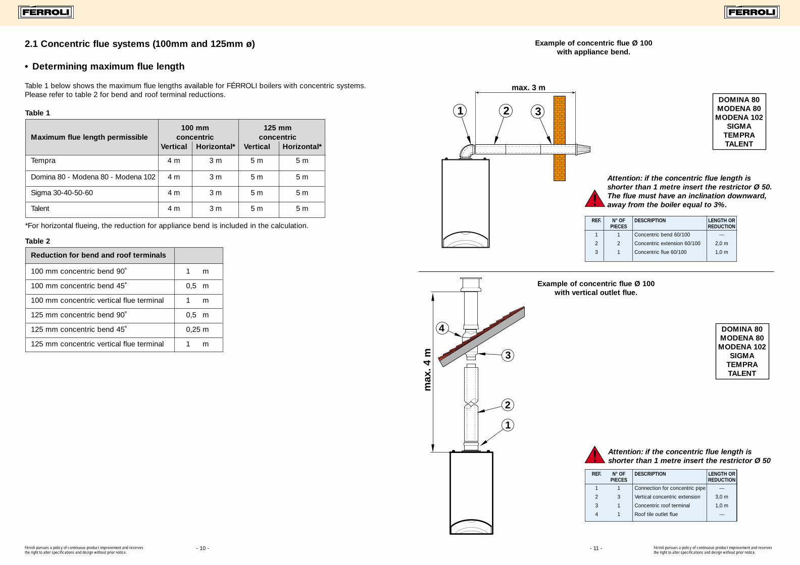
DOMINA 80MODENA 80MODENA 102
SIGMATEMPRATALENT
21 3
max. 3 m
Example of concentric flue Ø 100 with appliance bend.
Example of concentric flue Ø 100 with vertical outlet flue.
Attention: if the concentric flue length isshorter than 1 metre insert the restrictor Ø 50. The flue must have an inclination downward,away from the boiler equal to 3%.
REF. N° OF DESCRIPTION LENGTH OR PIECES REDUCTION
1 1 Concentric bend 60/100 —
2 2 Concentric extension 60/100 2,0 m
3 1 Concentric flue 60/100 1,0 m
2
1m
ax. 4
m
4
3
Attention: if the concentric flue length isshorter than 1 metre insert the restrictor Ø 50
REF. N° OF DESCRIPTION LENGTH OR PIECES REDUCTION
1 1 Connection for concentric pipe —
2 3 Vertical concentric extension 3,0 m
3 1 Concentric roof terminal 1,0 m
4 1 Roof tile outlet flue —
DOMINA 80MODENA 80MODENA 102
SIGMATEMPRATALENT
Férroli pursues a policy of continuous product improvement and reservesthe right to alter specifications and design without prior notice.
Férroli pursues a policy of continuous product improvement and reservesthe right to alter specifications and design without prior notice.
2.1 Concentric flue systems (100mm and 125mm ø)
• Determining maximum flue length
Table 1 below shows the maximum flue lengths available for FÉRROLI boilers with concentric systems.Please refer to table 2 for bend and roof terminal reductions.
Table 1
Table 2
- 10 -
100 mm 125 mmMaximum flue length permissible concentric concentric
Vertical Horizontal* Vertical Horizontal*
Tempra 4 m 3 m 5 m 5 m
Domina 80 - Modena 80 - Modena 102 4 m 3 m 5 m 5 m
Sigma 30-40-50-60 4 m 3 m 5 m 5 m
Talent 4 m 3 m 5 m 5 m
Reduction for bend and roof terminals
100 mm concentric bend 90˚ 1 m
100 mm concentric bend 45˚ 0,5 m
100 mm concentric vertical flue terminal 1 m
125 mm concentric bend 90˚ 0,5 m
125 mm concentric bend 45˚ 0,25 m
125 mm concentric vertical flue terminal 1 m
*For horizontal flueing, the reduction for appliance bend is included in the calculation.
S.p.A. S.p.A.S.p.A.
23??? férroli flue bro Feb 18/2/00 1:23 pm Page 13 (1,1)
- 13 -
2.2 Two pipe flue system (80mm Ø)
To determine the maximum flue length of flue and air pipe permissible.
The calculation is based on a standard reference resistance of 1 metre x 80 mm Ø horizontal airintake pipe.
For every configuration of the two-pipe system all components will have a resistance factor basedupon this reference. (i.e. a 90˚ bend fitted in the exhaust line would attract a resistance factorequivalent to 2.5 metres of horizontal 80mm pipe.)
This is expressed as X metres
Each boiler will have a maximum equivalent length of flue/air pipe and this is shown in the tableas N metres.
Therefore when calculating the proposed flue run the equivalent resistance of every length of pipeand every bend, whether air intake or flue discharge is added together to give an actual total fluelength.
The final figure calculated must not exceed the permitted maximum length (N metres) for eachboiler type.
Calculation Routine
1. Identify all the components needed to complete the proposed flue/air pipe run.
2. Calculate the sum of all the equivalent lengths.
3. For boilers which may require a flue restrictor, refer to table D1 to ascertain the correct size
and add this resistance to your total.
4. Check and verify that the total flue/air pipe length (flow resistance) does not exceed the
permitted maximum for the boiler type (table M1)
IMPORTANT!Resistance factors apply to standard Férroli components only.
The values for condensing boilers will be different.
Férroli pursues a policy of continuous product improvement and reservesthe right to alter specifications and design without prior notice.
Férroli pursues a policy of continuous product improvement and reservesthe right to alter specifications and design without prior notice.
- 12 -
Example of concentric flue Ø 125with vertical outlet flue
4
3
max
. 5 m
2
1
REF. N° OF DESCRIPTION LENGTH OR PIECES REDUCTION
1 1 Connection for concentric pipe —
2 4 Vertical concentric extension 4,0 m
3 1 Concentric roof terminal 1,0 m
4 1 Roof tile outlet flue —
2 31
max. 5 m
4
Example of concentric flue Ø 125with appliance bend
Attention: the flue must have an inclinationdownward away from the boiler equal to 3%.
REF. N° OF DESCRIPTION LENGTH OR PIECES REDUCTION
1 1 Concentric bend 80/125 —2 2 Concentric extension 80/125 2,0 m3 1 Concentric pipe 80/125 1,0 m4 1 Connection for 125/80 —
DOMINA 80MODENA 80
MODENA 102SIGMA
TEMPRATALENT
DOMINA 80MODENA 80
MODENA 102SIGMA
TEMPRATALENT
S.p.A. S.p.A.S.p.A.
23??? férroli flue bro Feb 18/2/00 1:23 pm Page 15 (1,1)

TAB. M1 - MAXIMUM FLUE LENGTH PERMISSIBLE 80MM 2 PIPE SYSTEM ‘X’ DIMENSION
- 15 -
6
7
3 12
4
8
5
°C
°C
Example of roof flue outlet and wall air inlet with 2 pipe system maximum total flue length: 38 metres
REF. N° OF DESCRIPTION LENGTH OR PIECES REDUCTION
1 1 Air wall terminal 2,0 m
2 1 Horizontal air pipe 1,0 m
3 1 Air bend 80 mm R/D = 0,75 1,5 m
4 1 Air inlet closing flange —
5 26,5 Vertical flue 80 mm 26,5 m
6 1 Roof terminal only for flue 4,0 m
7 1 Roof tile outlet flue —
8 1 Condensate outlet 3,0 m
TOTAL 38,0 m
26,5 m
TALENT
7
4
6 3215
°C
°C
Attention: the air and flue pipes must have aninclination downward away from boiler equalto 3%.
Example of wall inlet/outlet with 2 pipe systemMaximum total flue length: 38 metres
9 m
REF. N° OF DESCRIPTION LENGTH OR PIECES REDUCTION
1 1 Air bend 80 mm R/D = 0,75 1,5 m
2 9 Horizontal air pipe 9,0 m
3 1 Air wall terminal 2,0 m
4 1 Air inlet closing flange —
5 1 Flue bend 80 mm R/D = 0,75 2,5 m
6 9 Horizontal flue 18,0 m
7 1 Air wall terminal outlet flue 5,0 m
TOTAL 38,0 m
TALENT
Férroli pursues a policy of continuous product improvement and reservesthe right to alter specifications and design without prior notice.
Férroli pursues a policy of continuous product improvement and reservesthe right to alter specifications and design without prior notice.
- 14 -
FÉRROLI wall Hung Boilers: Max LENGTH for flue systems
First table below shows the maximum flue lengths available for FÉRROLI boilers with the different flueoptions (concentrics and 2 pipe systems). For correct calculation refer to the reductions for bend and pipepositioning listed on second table.
Choice of the restrictor with separate pipes:
1 Calculate the total flow resistance of the air and flue pipes in equivalent m/air.
2 From the table D1 shown above to choose the most suitable restrictor for the flow resistance calculated.
3 To complete the calculation, add the diaphragm flow resistance to the total flow resistance ofthe pipes, check that total is less than maximum permitted in table M1.
Domina 80 - Modena 80 48 m
Sigma 40 m
Talent 38 m
Tempra 55 m
S.p.A. S.p.A.S.p.A.
minimum maximum mm
0 mm 13 mm 45 35 m
13 mm 23 mm 47 25 m
23 mm 38 mm 50 10 m
38 mm 48 mm no restrictor 0 m
Total flow resistanceof flue system
RestrictorSize Restrictor
reduction
TAB. D1-RESTRICTOR CALCULATION FOR DOMINA 80 - MODENA 80/102 ‘N’ DIMENSION
23??? férroli flue bro Feb 18/2/00 1:23 pm Page 17 (1,1)

- 17 -
1
2
4
3
5
Example of roof inlet/outlet with 2 pipe systemmaximum total flue length: 48 metres
Attention: example of maximum length guaranteed by the fan. In theseconditions it is necessary to insulatethe flue+air pipe to protect the boilerfrom condensation.Flow resistance (reduction) equivalent isapplicable between 38 and 48 (see tableD1) Remove the flue restrictor.
REF. N° OF DESCRIPTION LENGTH OR PIECES REDUCTION
1 18 Vertical air pipe 80 mm 18,0 m
2 1 Roof air-flue terminal 12,0 m
3 1 Air inlet closing flange —
4 18 Vertical flue 80 mm 18,0 m
5 1 Roof tile outlet flue —
TOTAL 48,0 m
18 m
DOMINA 80 - MODENA 80/102
Example of concentric roof flue outlet and wall air inlet with 2 pipe system
maximum total flue length: 40 metres
REF. N° OF DESCRIPTION LENGTH OR PIECES REDUCTION
1 1 Air wall terminal 2,0 m
2 1 Horizontal air pipe 1,0 m
4 1 Air/flue T separator —
5 30 Vertical flue 80 mm 30,0 m
6 1 Roof terminal only for flue 4,0 m
7 1 Roof tile outlet flue —
8 1 Condensate outlet 3,0 m
TOTAL 40,0 m
30 m
SIGMA
1 25
4
6
7
8
Warning: Rear exit with air/flue T separator is not allowed.
Férroli pursues a policy of continuous product improvement and reservesthe right to alter specifications and design without prior notice.
Férroli pursues a policy of continuous product improvement and reservesthe right to alter specifications and design without prior notice.
- 16 -
7
4
6 325 1
12 m 12 m
Attention: flow resistance (reduction) equivalentincluded between 38 and 48 (see table D1)Remove the flue restrictor.The flue and air pipes must have an inclinationdownward away from boiler equal to 3%.
Example of wall inlet/outlet with 2 pipe systemmaximum total flue length: 48 metres
12 m
REF. N° OF DESCRIPTION LENGTH OR PIECES REDUCTION
1 1 Air bend 80 mm R/D = 0,75 1,5 m
2 12 Horizontal air pipe 12,0 m
3 1 Air wall terminal 2,0 m
4 1 Air inlet closing flange —
5 1 Flue bend 80 mm R/D = 0,75 2,5 m
6 12 Horizontal flue 24,0 m
7 1 Air wall terminal outlet flue 5,0 m
TOTAL 47,0 m
DOMINA 80 - MODENA 80/102
Flow resistance (reduction) equivalentincluded between 38 and 48 (see table D1)Remove the flue restrictor.
6
7
3 12
4
8
5
36,5 m
REF. N° OF DESCRIPTION LENGTH OR PIECES REDUCTION
1 1 Air wall terminal 2,0 m
2 1 Horizontal air pipe 1,0 m
3 1 Air bend 80 mm R/D = 0,75 1,5 m
4 1 Air inlet closing flange —
5 36,5 Vertical flue 80 mm 36,5 m
6 1 Roof terminal only for flue 4,0 m
7 1 Roof tile outlet flue —
8 1 Condensate outlet 3,0 m
TOTAL 48,0 m
DOMINA 80 - MODENA 80/102
Example of roof flue outlet and wall air inlet with 2 pipe system maximum total flue length: 48 metres
S.p.A. S.p.A.S.p.A.
23??? férroli flue bro Feb 18/2/00 1:23 pm Page 19 (1,1)

- 19 -
• Minimum cross section for flue gas discharge pipes for collective systems
The values in these tables are valid only for FÉRROLI room-sealed compartment, fanned flue boilers.
Components not supplied by Férroli Ltd. are permitted providing the performance and designdetails are submitted to Férroli R & D for approval.
MINIMUM CROSS SECTIONS FOR AIR INTAKE PIPES
CONCENTRIC PIPES Aa = FROM 2.5 TO 3.5 TIMES THE Fe CROSS SECTION
PARALLEL PIPES Aa = FROM 2 TO 3 TIMES THE Fe CROSS SECTION
Aa AIR INLET PIPE INTERNAL CROSS SECTION
Fe FLUE GAS EVACUATION PIPE INTERNAL CROSS SECTION
No. units Square section Round sectionconnected concrete pipes (Fe.) metal pipes (Fe.)
2 150 150
3 200 200
4 250 250
5 350 315
6 450 380
7 550 440
8 650 505
9 700 565
10 750 630
11 800 660
12 850 720
13 900 780
14 950 840
15 1000 900
16 1050 910
17 1100 970
18 1150 1025
19 1200 1085
20 1250 1140
2.3 Collective flue systems
Férroli pursues a policy of continuous product improvement and reservesthe right to alter specifications and design without prior notice.
Férroli pursues a policy of continuous product improvement and reservesthe right to alter specifications and design without prior notice.
765
2 1
43
- 18 -
Attention: the air and flue pipes must have aninclination downward away from boiler equalto 3%.
Example of horizontal inlet/outlet with 2 pipe systemMaximum total flue length: 40 metres
10 m
REF. N° OF DESCRIPTION LENGTH OR PIECES REDUCTION
1 10 Horizontal air pipe 10,0 m
2 1 Air wall terminal 2,0 m
3 1 Connection for concentric pipe —
4 1 Air/flue T separator —
5 1 Flue bend 80 mm R/D = 0,75 2,5 m
6 10 Horizontal flue 20,0 m
7 1 Air wall terminal outlet flue 5,0 m
TOTAL 39,5 m
SIGMA
Warning: Rear exit with air/flue T separator isnot permitted.
S.p.A. S.p.A.S.p.A.
23??? férroli flue bro Feb 18/2/00 1:23 pm Page 21 (1,1)

- 21 -
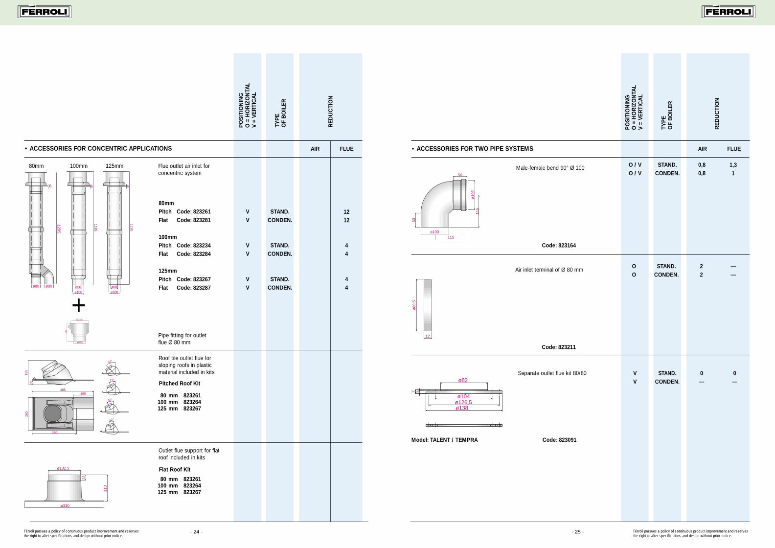
• Accessories for concentric systems
Concentric bend 90°, rotation 360° in steps of 45°, Ø 100/60 mm, with flange.
Code: 823034
3. Accessories for flue systems
FOR BOILERS:
Connection for concentric pipe Ø 100/60 mm. TALENTTEMPRAø62
ø100.5
ø80
5311
0
ø126,4
TALENT
ø95
ø60
.2
ø10
0
øe 80
ø60.2ø126.4
96
Code: 823064
Connection for concentric pipe Ø 100/60 mm.
Code: 823074
DOMINA 80MODENA 80/102
ø100.5ø62
ø80
102.
56810
1
ø138ø126,5
ø95
ø60
.2
ø80
ø60.2
ø11
2
ø126
148
Concentric bend 90°, rotation 360° in steps of 45°, Ø 100/60 mm, with flange.
Modena/Domina: 823044Sigma: 823045
DOMINA 80MODENA 80/102SIGMA 30-60
Férroli pursues a policy of continuous product improvement and reservesthe right to alter specifications and design without prior notice.
Férroli pursues a policy of continuous product improvement and reservesthe right to alter specifications and design without prior notice.
- 20 -
The diagram below shows applications into collective flue systems
FLUEAIR AIR
FLUE AIR
FLUE AIR
AIR
FLUE AIR
S.p.A. S.p.A.S.p.A.
23??? férroli flue bro Feb 18/2/00 1:24 pm Page 23 (1,1)

- 23 -
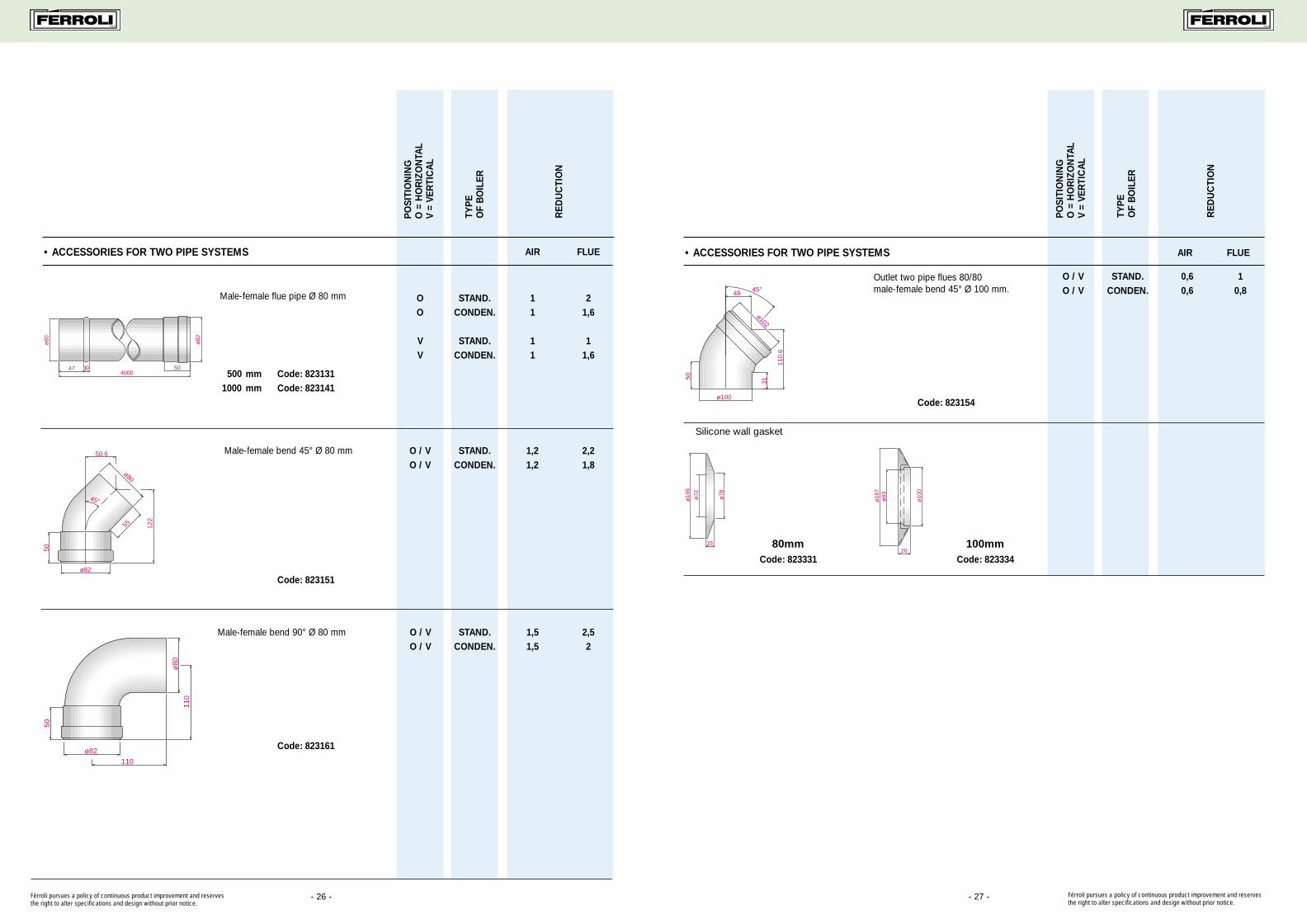
• Accessories for concentric systems FOR BOILERS:
100050
ø 8
2ø
127
ø 8
0ø
125
Concentric extension male/female internal Ø 60 mm in aluminium, external Ø 100 complete with gaskets.
ALL MODELS
Silicone wall gasket ø 125 mm ALL MODELS
ø22
0ø
118
33
ø12
5
Férroli pursues a policy of continuous product improvement and reservesthe right to alter specifications and design without prior notice.
- 22 -
• Accessories for concentric systems FOR BOILERS
Code: 8231048
52
790
750
60100
Internal aluminium concentric pipe Ø 60 mm, external Ø 100 mm, complete with terminal and wall gaskets.
Plastic external white coloured, L = 750mm.
ALL MODELS
80 mm Code: 823131100 mm Code: 823134125 mm Code: 823137
80 mm Code: 23151100 mm Code: 23154125 mm Code: 23157
80 mm Code: 823161100 mm Code: 823164125 mm Code: 823167
80 mm Code: 823141100 mm Code: 823144125 mm Code: 823147
80 mm Code: 823331100 mm Code: 823334125 mm Code: 823337
Concentric extension male/female internal Ø 60 mm in aluminium, external Ø 100 complete with gaskets.
ALL MODELS
ø80ø125
ø82ø127
50
45°
307,
5
71,5
5
122
30
Concentric bend 45˚, complete with gaskets. ALL MODELS
ø80ø125
ø12
7ø
82
110
40,5
110
Concentric bend 90°, complete with gaskets ALL MODELS
Férroli pursues a policy of continuous product improvement and reservesthe right to alter specifications and design without prior notice.
S.p.A. S.p.A.S.p.A.
23??? férroli flue bro Feb 18/2/00 1:24 pm Page 25 (1,1)
- 25 - Férroli pursues a policy of continuous product improvement and reservesthe right to alter specifications and design without prior notice.
PO
SITI
ON
ING
O =
HO
RIZ
ON
TAL
V =
VER
TIC
AL
TYP
EO
F B
OIL
ER
RED
UC
TIO
N
AIR FLUE• ACCESSORIES FOR TWO PIPE SYSTEMS
ø80
.5
12
OO
STAND.CONDEN.
——
22
Code: 823211
Air inlet terminal of Ø 80 mm
ø100
ø10
2
50
50
115
115
O / VO / V
STAND.CONDEN.
0,80,8
1,31
Male-female bend 90° Ø 100
Code: 823164
Separate outlet flue kit 80/80ø82
ø1387 5
ø126,5ø104
Code: 823091Model: TALENT / TEMPRA
VV
STAND.CONDEN.
0—
0—
- 24 -Férroli pursues a policy of continuous product improvement and reservesthe right to alter specifications and design without prior notice.
1195
6
ø60ø100
ø125.5
ø80.5
5013
0
350
260
160485
3519
5
41°
23°
30°
12°
ø330
22
110
ø132.5
VV
STAND.CONDEN.
44
VV
STAND.CONDEN.
1212
VV
STAND.CONDEN.
44
AIR FLUE
Flue outlet air inlet forconcentric system
80mm 100mm 125mm
Pipe fitting for outletflue Ø 80 mm
Pitched Roof Kit
Flat Roof Kit
Roof tile outlet flue for sloping roofs in plastic material included in kits
Outlet flue support for flat roof included in kits
• ACCESSORIES FOR CONCENTRIC APPLICATIONS
PO
SITI
ON
ING
O =
HO
RIZ
ON
TAL
V =
VER
TIC
AL
TYP
EO
F B
OIL
ER
RED
UC
TIO
N
+
80mmPitch Code: 823261Flat Code: 823281
100mmPitch Code: 823234Flat Code: 823284
125mmPitch Code: 823267Flat Code: 823287
1295
ø80 ø80
6
1195
6
ø60ø100
S.p.A. S.p.A.S.p.A.
80 mm 823261100 mm 823264125 mm 823267
80 mm 823261100 mm 823264125 mm 823267
23??? férroli flue bro Feb 18/2/00 1:24 pm Page 27 (1,1)
S.p.A. S.p.A.S.p.A.
- 27 - Férroli pursues a policy of continuous product improvement and reservesthe right to alter specifications and design without prior notice.
AIR FLUE• ACCESSORIES FOR TWO PIPE SYSTEMS
PO
SITI
ON
ING
O =
HO
RIZ
ON
TAL
V =
VER
TIC
AL
TYP
EO
F B
OIL
ER
RED
UC
TIO
N
ø100
ø102
45°
31
110.
6
49
50
O / VO / V
STAND.CONDEN.
0,60,6
10,8
Outlet two pipe flues 80/80 male-female bend 45° Ø 100 mm.
Code: 823154
Silicone wall gasket
ø14
6
ø72 ø78
15
Code: 823331
ø16
7ø
93
20
ø10
0
Code: 823334
• ACCESSORIES FOR TWO PIPE SYSTEMS AIR FLUE
PO
SITI
ON
ING
O =
HO
RIZ
ON
TAL
V =
VER
TIC
AL
TYP
E O
F B
OIL
ER
RED
UC
TIO
N
ø80 ø82
50474000
10
OO
VV
STAND.CONDEN.
STAND.CONDEN.
11
11
21,6
11,6
Male-female flue pipe Ø 80 mm
500 mm Code: 8231311000 mm Code: 823141
Code: 823151
Code: 823161
- 26 -
ø82
50
ø8055
45°
50.6
122
O / VO / V
STAND.CONDEN.
2,21,8
1,21,2
Male-female bend 45° Ø 80 mm
Male-female bend 90° Ø 80 mm
ø80
50
ø82
110
110
O / VO / V
STAND.CONDEN.
1,51,5
2,52
Férroli pursues a policy of continuous product improvement and reservesthe right to alter specifications and design without prior notice.
80mm 100mm
23??? férroli flue bro Feb 18/2/00 1:24 pm Page 29 (1,1)

NOTES NOTES
S.p.A. S.p.A.S.p.A.
23??? férroli flue bro Feb 18/2/00 1:24 pm Page 31 (1,1)