operating procedure – allwin21 aw 610 rtp (rapid thermal ... · operating procedure – allwin21...
TRANSCRIPT

(Rapid Thermal Annealing)
Operating Procedure – Allwin21 AW 610 RTP
Prepared by
Hemant Kumar Singh
based on
Main manual provided by Allwin21 and discussion with Allwin21 service engineer David Chang, USA
National Centre for Photovoltaic Research and Education (NCPRE) Indian Institute of Technology- Bombay
Powai, Mumbai-400076 INDIA
1/15 Main SOP/H.K.S
Pre check before entering in the lab for RTP Process
Step: 1 . Check if any other tools in Fab Lab is ON or not. If any other tool (PECVD, Edge
isolation tool) is/are ON, then enquire from facility people if you can use RTP as some
gases are on sharing basis.
Step: 2 . Check if cooling water is ON [Set pressure should be 25 -30 psi (~ 2 bar)].
Step: 3 . Check if water supply to Pyrometer is ON [Set temperature should be 20 0
Step: 4 . Check if exhaust is ON (Ask facility people if not sure).
C and
stable].
Step: 5 . Check if CDA is available and ON (Ask facility people if not sure).
Step: 6 . Check the process gases N2
Step: 7 . Wait for 10 minutes to stabilize all the flow and setups.
or Ar which you want to use is ON [[Set pressure should
be 20 psi]. [Gases, which are available for RTP, are Nitrogen, Oxygen and Argon].
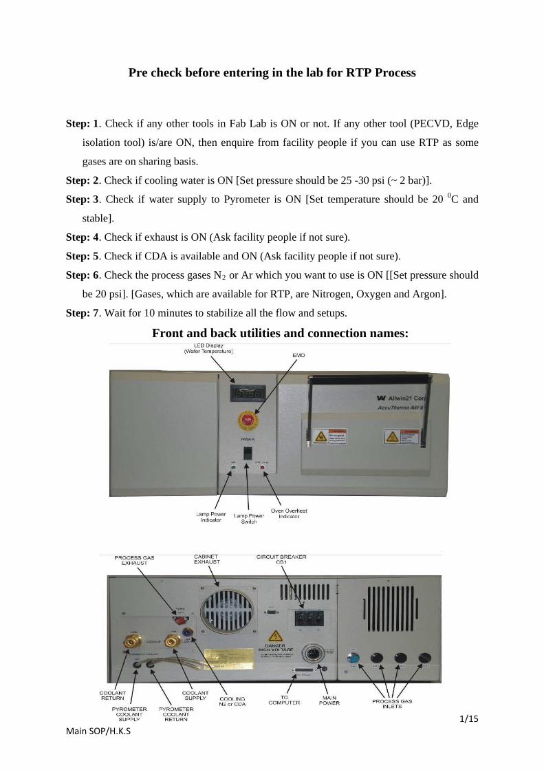
Front and back utilities and connection names:
2/15 Main SOP/H.K.S
System Power UP
Step: 1. Ensure that you have followed step 1 – 7 as mentioned in “Pre check before entering
in the lab for RTP Process
Step: 2. Open the valve for CDA which is connected to regulators of MFC and Air cooling.
”.
Step: 3. Crosscheck if CDA regulator for Pneumatics valve is set at 70 psi. [Consult Facility
people] and the regulator is ON.
Step: 4. Crosscheck if CDA regulator for Air-cooling for system is set at 20 psi. [Consult
Facility people] and the regulator is ON.
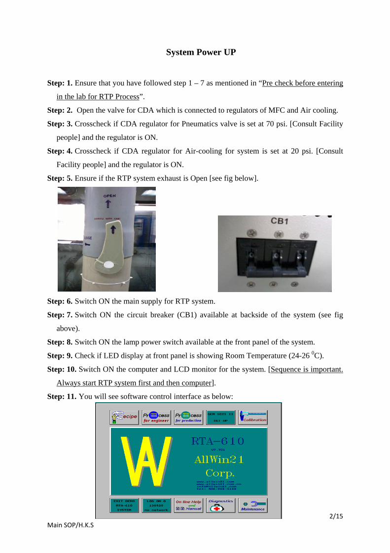
Step: 5. Ensure if the RTP system exhaust is Open [see fig below].
Step: 6. Switch ON the main supply for RTP system.
Step: 7. Switch ON the circuit breaker (CB1) available at backside of the system (see fig
above).
Step: 8. Switch ON the lamp power switch available at the front panel of the system.
Step: 9. Check if LED display at front panel is showing Room Temperature (24-26 0
Step: 10. Switch ON the computer and LCD monitor for the system. [
C).
Sequence is important.
Always start RTP system first and then computer
Step: 11. You will see software control interface as below:
].
3/15 Main SOP/H.K.S
Step: 12. In case if you see command window then type rtapro
Step: 13. Ensure that there is no wafer/sample left inside by someone in the process
chamber of RTP except the test wafer, which is for balancing the thermocouple bead for
free movement of thermocouple without interfering the walls of the chamber.
and then press enter. This
will lead you to interface as above.
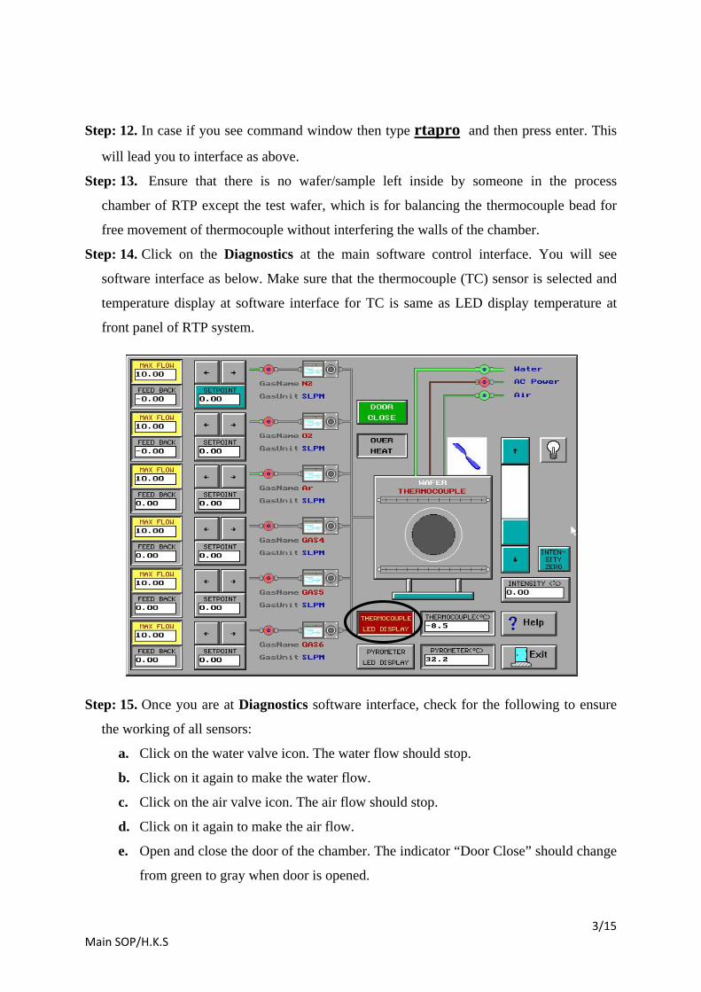
Step: 14. Click on the Diagnostics at the main software control interface. You will see
software interface as below. Make sure that the thermocouple (TC) sensor is selected and
temperature display at software interface for TC is same as LED display temperature at
front panel of RTP system.
Step: 15. Once you are at Diagnostics software interface, check for the following to ensure
the working of all sensors:
a. Click on the water valve icon. The water flow should stop.
b. Click on it again to make the water flow.
c. Click on the air valve icon. The air flow should stop.
d. Click on it again to make the air flow.
e. Open and close the door of the chamber. The indicator “Door Close” should change
from green to gray when door is opened.

4/15 Main SOP/H.K.S
f. Open the process gas valve [N2
g. Check if thermocouple is connected properly inside the chamber (the two wires of
thermocouple should not touch anywhere except at end point). If yes then place a
dummy wafer inside on the quartz tray such that the tip of the cantilever
thermocouple touching the backside of the wafer. Close the chamber door after this
check.
or Ar which ever is open or to be used] and set 3 to
5 SLPM of selected process gas flow in software interface to ensure tube purging.
Observe that there is gas flow being displayed on the Diagnostics screen in flow
feedback section. [The chamber door can be opened slightly (1 cm) during this test
and again close it].
h. Set the lamp intensity to 5 % in the Diagnostic screen and ensure that
“Thermocouple Led display” is selected in the software interface and then click on
the lamp icon. Observe the rise in the thermocouple (TC) section in the software
interface. It should increase if so then TC is working fine. Also observe that the
displaying temperature is same as Led display temperature at the front panel of the
RTP system. [Note that this test should be done quickly in short duration so
that temperature should not rise above 200 0
Note: For high temp process ( > 700
C. Also there should be a dummy
wafer inside to ensure the heat sink] Once test is done, then click again on the
lamp icon to stop the lamp. Also set the lamp intensity to back to 0 % in the
Diagnostic screen. 0C) on Si wafer, you need to remove the
thermocouple arrangement from the chamber and in that case you should select
“Pyrometer LED display” in the software interface to test the temperature rise with
intensity. Also note that Pyrometer is not sensitive below 500 0
Step: 16. Click on Exit icon to go to main menu.
C temperature.
If all the steps from Step 1- 15 is OK, then the system is ready for Process. If you find any
abnormality, contact the System Owner/technical person.

5/15 Main SOP/H.K.S
Process Recipe making/editing or running
Step: 1. If you are sure that the system is ready for process after following the “System
Power UP” steps 1 -15, then follow as below.
Step: 2. Go to main menu which looks as below:
Step: 3. Click on “Process for Engineer” icon.

6/15 Main SOP/H.K.S
Step: 4. Now to create or modify recipe follow steps 5 -32. Creating a new recipe and editing
an existing recipe are very similar. The differences between creating a new recipe and
editing an existing recipe occur when the changes are saved. Creating a new recipe also
involves changing the Recipe Name field.
Step: 5. Use the slider to the right of the list to display. Click on the Recipe to select it. Click
on the Recipe Edit button to display the Recipe Editor for any pre existing recipe to make
new recipe. Check all the parameters are correct and as per wish for the process. For this,
follow the following.
Step: 6. After selecting a pre-existing Recipe by click on the “Recipe edit” icon. You will be at a interface as below:

7/15 Main SOP/H.K.S
(Note in the above figure when Thermocouple sensor is selected, there is no INTN step at no. 2 in edit section. So whenever use thermocouple, don’t use INTN step. It may be used when you wish fast ramp up but not advisable here. But INTN step is must if pyrometer is to be used as main sensor.)
Step: 7. Edit it. (If a new Recipe is to be created, also change the Recipe Name field before
saving.)
Step: 8. For editing the recipe parameters follow the following.
Step: 9. The editor is divided into two main sections. The top section (header) is where the
user inputs information pertinent to the overall recipe. The lower section (data entry area)
is for the process recipe data entry.
Step: 10. The Recipe Name can be edited. This should be done if a new recipe is to be
created. Follow the structure for recipe ID as (Temp)(Sensor-TC/PY) e.g. 500TC or
550PY (note that the name should not exceed 5 digits). Also leave the EXT field as RCP.
This is the filename extension and the AW-900 software expects it to be RCP for a recipe.
Step: 11. Wafer type wafer button on header of edit pages as figure above toggles between
“wafer” and “susceptor”. Default value is “wafer”. For small samples, it may be required
to use a susceptor to hold the wafer inside. Also note that it is necessary to use a different
type of chamber calibration data specific for the susceptor. When use susceptor, follow
Appendix – I before you move to next Step: 12.
Step: 12. Sensor type thermocouple button on header of edit pages as figure above is for the
temperature measurement sensor and can be toggled between the TC, pyrometer. Choose
appropriate sensor, which you are going to use. (For Pyrometer use, the temperature
should be > 600 0C and for TC the temperature should be < 700 0
Caution: Make sure the proper sensor is selected. A selected sensor that is not installed
could give low temperature readings. This would make the temperature control increase
the lamp intensity too much and may overheat and melt the wafer. The melted wafer could
drip onto the quartzware and break it.
C unless specified.
Also when use TC, make sure that thermocouple is connected in the chamber and working
fine).
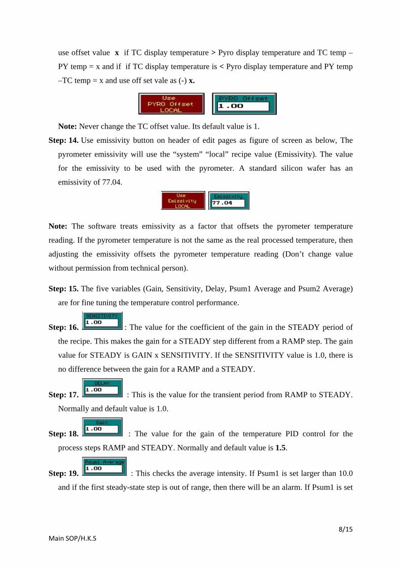
Step: 13. Use pyro offset button on header of edit pages as figure below, to use of the
“system” “local” recipe value (Pyro Offset) for the pyrometer temperature measurement-
correcting offset. To determine required offset value, use data from processing which is
done earlier on process temperature on TC sensor based process for above 500 0C. Then
8/15 Main SOP/H.K.S
use offset value x if TC display temperature > Pyro display temperature and TC temp –
PY temp = x and if if TC display temperature is < Pyro display temperature and PY temp
–TC temp = x and use off set vale as (-) x.
Note: Never change the TC offset value. Its default value is 1.
Step: 14. Use emissivity button on header of edit pages as figure of screen as below, The
pyrometer emissivity will use the “system” “local” recipe value (Emissivity). The value
for the emissivity to be used with the pyrometer. A standard silicon wafer has an
emissivity of 77.04.
Note: The software treats emissivity as a factor that offsets the pyrometer temperature
reading. If the pyrometer temperature is not the same as the real processed temperature, then
adjusting the emissivity offsets the pyrometer temperature reading (Don’t change value
without permission from technical person).
Step: 15. The five variables (Gain, Sensitivity, Delay, Psum1 Average and Psum2 Average)
are for fine tuning the temperature control performance.
Step: 16. : The value for the coefficient of the gain in the STEADY period of
the recipe. This makes the gain for a STEADY step different from a RAMP step. The gain
value for STEADY is GAIN x SENSITIVITY. If the SENSITIVITY value is 1.0, there is
no difference between the gain for a RAMP and a STEADY.
Step: 17. : This is the value for the transient period from RAMP to STEADY.
Normally and default value is 1.0.
Step: 18. : The value for the gain of the temperature PID control for the
process steps RAMP and STEADY. Normally and default value is 1.5.
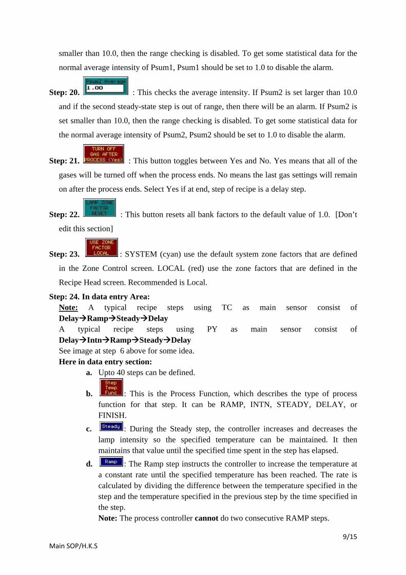
Step: 19. : This checks the average intensity. If Psum1 is set larger than 10.0
and if the first steady-state step is out of range, then there will be an alarm. If Psum1 is set
9/15 Main SOP/H.K.S
smaller than 10.0, then the range checking is disabled. To get some statistical data for the
normal average intensity of Psum1, Psum1 should be set to 1.0 to disable the alarm.
Step: 20. : This checks the average intensity. If Psum2 is set larger than 10.0
and if the second steady-state step is out of range, then there will be an alarm. If Psum2 is
set smaller than 10.0, then the range checking is disabled. To get some statistical data for
the normal average intensity of Psum2, Psum2 should be set to 1.0 to disable the alarm.
Step: 21. : This button toggles between Yes and No. Yes means that all of the
gases will be turned off when the process ends. No means the last gas settings will remain
on after the process ends. Select Yes if at end, step of recipe is a delay step.
Step: 22. : This button resets all bank factors to the default value of 1.0. [Don’t
edit this section]
Step: 23. : SYSTEM (cyan) use the default system zone factors that are defined
in the Zone Control screen. LOCAL (red) use the zone factors that are defined in the
Recipe Head screen. Recommended is Local.
Step: 24. In data entry Area: Note:
A typical recipe steps using PY as main sensor consist of DelayIntnRampSteadyDelay
A typical recipe steps using TC as main sensor consist of DelayRampSteadyDelay
See image at step 6 above for some idea. Here in data entry section:
a. Upto 40 steps can be defined.
b. : This is the Process Function, which describes the type of process function for that step. It can be RAMP, INTN, STEADY, DELAY, or FINISH.
c. : During the Steady step, the controller increases and decreases the lamp intensity so the specified temperature can be maintained. It then maintains that value until the specified time spent in the step has elapsed.
d. : The Ramp step instructs the controller to increase the temperature at a constant rate until the specified temperature has been reached. The rate is calculated by dividing the difference between the temperature specified in the step and the temperature specified in the previous step by the time specified in the step. Note: The process controller cannot do two consecutive RAMP steps.
10/15 Main SOP/H.K.S
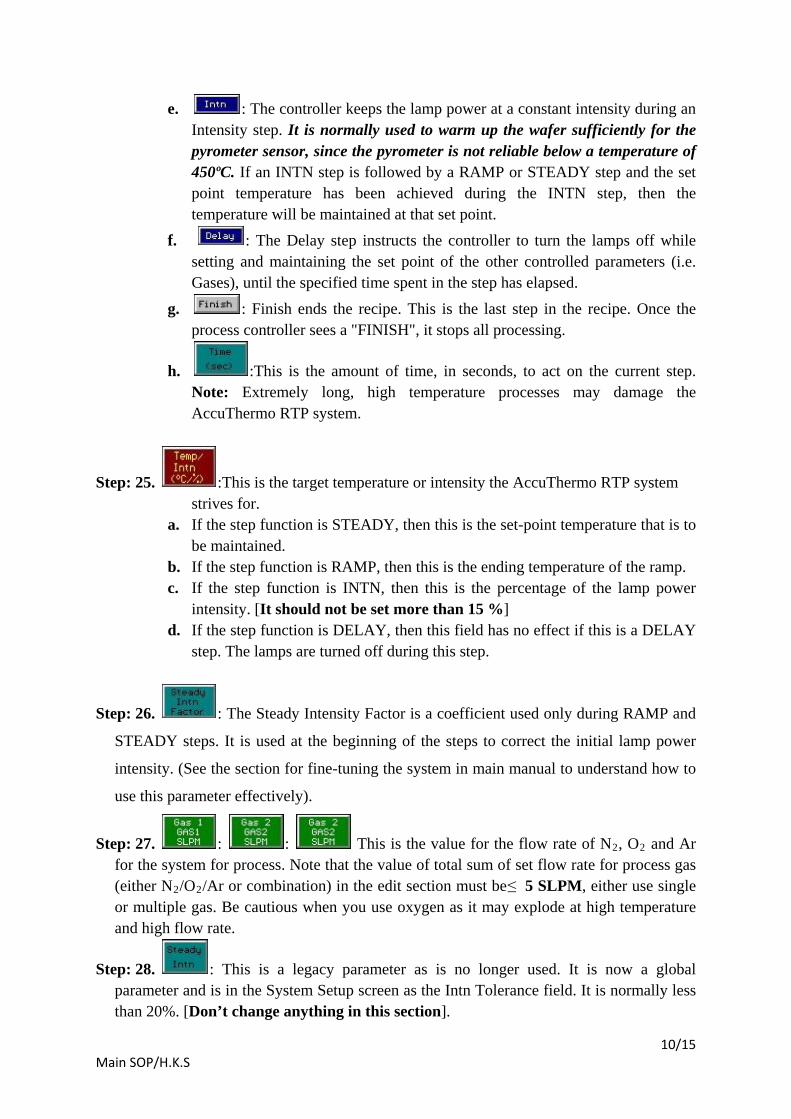
e. : The controller keeps the lamp power at a constant intensity during an Intensity step. It is normally used to warm up the wafer sufficiently for the pyrometer sensor, since the pyrometer is not reliable below a temperature of 450ºC. If an INTN step is followed by a RAMP or STEADY step and the set point temperature has been achieved during the INTN step, then the temperature will be maintained at that set point.
f. : The Delay step instructs the controller to turn the lamps off while setting and maintaining the set point of the other controlled parameters (i.e. Gases), until the specified time spent in the step has elapsed.
g. : Finish ends the recipe. This is the last step in the recipe. Once the process controller sees a "FINISH", it stops all processing.
h. :This is the amount of time, in seconds, to act on the current step. Note: Extremely long, high temperature processes may damage the AccuThermo RTP system.
Step: 25. :This is the target temperature or intensity the AccuThermo RTP system strives for.
a. If the step function is STEADY, then this is the set-point temperature that is to be maintained.
b. If the step function is RAMP, then this is the ending temperature of the ramp. c. If the step function is INTN, then this is the percentage of the lamp power
intensity. [It should not be set more than 15 %] d. If the step function is DELAY, then this field has no effect if this is a DELAY
step. The lamps are turned off during this step.
Step: 26. : The Steady Intensity Factor is a coefficient used only during RAMP and
STEADY steps. It is used at the beginning of the steps to correct the initial lamp power
intensity. (See the section for fine-tuning the system in main manual to understand how to
use this parameter effectively).
Step: 27. : : This is the value for the flow rate of N2, O2 and Ar for the system for process. Note that the value of total sum of set flow rate for process gas (either N2/O2
Step: 28. : This is a legacy parameter as is no longer used. It is now a global parameter and is in the System Setup screen as the Intn Tolerance field. It is normally less than 20%. [Don’t change anything in this section].
/Ar or combination) in the edit section must be ≤ 5 SLPM, either use single or multiple gas. Be cautious when you use oxygen as it may explode at high temperature and high flow rate.

11/15 Main SOP/H.K.S
Step: 29. Validate the Recipe by clicking on the “Recipe validate” icon. If the recipe is
invalid, an error message will appear. Once the error has been corrected, validate the
recipe again. The five variables (Gain, Sensitivity, Delay, Psum1 Average and Psum2
Average) are for fine-tuning the temperature control performance.
Step: 30. Save the Recipe by clicking on “save” icon.
Step: 31. Exit the Recipe Editor by clicking on the Exit button or pressing ESC on the
keyboard. If exiting the Recipe Editor before saving the recipe, a dialog box will appear
asking if the recipe should be saved.
a. Click Yes (or press Y on the keyboard) to save the recipe.
b. Click No (or press N on the keyboard) to discard all changes since the last
save.
c. Click Cancel (or press ESC on the keyboard) to go back to the Recipe Editor
and continue editing the recipe. It does not save any changes
Some shortcut keys are listed here:

12/15 Main SOP/H.K.S
Note: Other sections, which are not discussed here, like “Bank Factor Reset” button,
“Use System bank factor” button, “Recipe Head” button, “Bank Control” button,
Never
test or edit these sections without permission.
Step: 32. After exiting the “Recipe editor”, will be back at the “Process for Engineer”
control interface as below.
Step: 33. After editing recipe, select where the Process Data will be stored: The process data
is stored on the hard drive after the process ends. The place on the hard drive it will be
stored needs to be specified. Check, it should be Disk D (display in red colour).
Step: 34. Select a “Dir ID” e.g YYYY.MM and a “Lot ID” eg. DDMMYYYY from the list
of Directory IDs and Lot IDs. The Data ID will be generated automatically as per Recipe
ID after process.
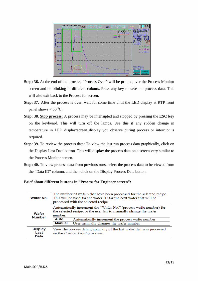
Step: 35. Run the Recipe: To run the selected Recipe, click on the Start Process button. This
will display the Process Monitor screen (see figure below). When this screen is displayed,
the process will begin processing the wafer inside the heating chamber according to the
selected Recipe. (Note: If you experience any problem/feel something wrong in
temperature sensor, immediately press ESC button / use Emergency switch (EMO) at RTP
front panel).
13/15 Main SOP/H.K.S
Step: 36. At the end of the process, “Process Over” will be printed over the Process Monitor
screen and be blinking in different colours. Press any key to save the process data. This
will also exit back to the Process for screen.
Step: 37. After the process is over, wait for some time until the LED display at RTP front
panel shows < 50 0
Step: 38. C.
Stop process:
Step: 39. To review the process data: To view the last run process data graphically, click on
the Display Last Data button. This will display the process data on a screen very similar to
the Process Monitor screen.
A process may be interrupted and stopped by pressing the ESC key
on the keyboard. This will turn off the lamps. Use this if any sudden change in
temperature in LED display/screen display you observe during process or interrupt is
required.
Step: 40. To view process data from previous runs, select the process data to be viewed from
the “Data ID” column, and then click on the Display Process Data button.
Brief about different buttons in “Process for Engineer screen”:

14/15 Main SOP/H.K.S

15/15 Main SOP/H.K.S
System Power Down
Note: Be alert at all times during power-up. If at any time during these procedures the
lamps turn on at high intensity unexpectedly, immediately turn the power switch OFF.
The system can heat up a wafer very rapidly until it melts. This can cause extensive
damage to the AccuThermo RTP system.
Do Not Power-Down the AccuThermo RTP system unless it has been more than 10
minutes since the last use of the unit. Let the system cool down with cooling water and
cooling air.
Step: 1. Turn off the gas valves for process gases in use.
Step: 2. Turn off the oven unit LAMP POWER switch (on the oven unit control panel.)
Step: 3. Turn off the facilities breaker/safety switch (CB1) at the back of RTP system.
Step: 4. Turn off the facilities breaker switch main.
Step: 5. Turn off the CDA valve to regulators of MFC and Air cooling.
Step: 6. Turn off the quartz isolation tube cooling CDA/nitrogen [Ask facility person].
Step: 7. Turn off the pyrometer chiller water dedicated for RTP system. [Ask facility person].
Step: 8. Turn off the oven cooling chiller water dedicated for RTP system [Ask facility
person].
Step: 9. Turn off the CPU and Computer monitor.
1 Appendix-I/H.K.S
Appendix -I
Susceptor
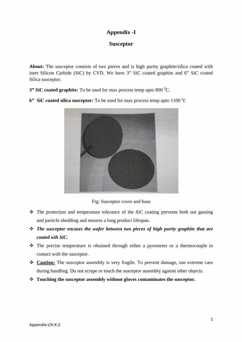
About: The susceptor consists of two pieces and is high purity graphite/silica coated with inert Silicon Carbide (SiC) by CVD. We have 3” SiC coated graphite and 6” SiC coated Silica susceptor.
3” SiC coated graphite: To be used for max process temp upto 800 0
6” SiC coated silica susceptor: To be used for max process temp upto 1100
C.
0
C
Fig: Susceptor cover and base
The protection and temperature tolerance of the SiC coating prevents both out gassing
and particle shedding and ensures a long product lifespan.
The susceptor encases the wafer between two pieces of high purity graphite that are
coated wih SiC.
The precise temperature is obtained through either a pyrometer or a thermocouple in
contact with the susceptor.
Caution:
Touching the susceptor assembly without gloves contaminates the susceptor.
The susceptor assembly is very fragile. To prevent damage, use extreme care
during handling. Do not scrape or touch the susceptor assembly against other objects.
2 Appendix-I/H.K.S
Examine the silicon carbide coating of the susceptor: look for cracks and severe pitting.
Using the Susceptor:
CAREFULLY place the susceptor on the pins of the quartz tray. The susceptor rests on
the quartz tray to increase the heating and cooling rate.
Place your samples inside the grooved area of the susceptor and cover it with susceptor
cover properly. Now this is like as you process wafer directly on quartz tray.
CAREFULLY remove the susceptor assembly from the quartz tray and place the
susceptor on a clean flat surface.
When removing the cover from the base, turn it over so the top of the cover is facing
down. This is to prevent the surface that faces the wafer from getting contaminated.
When placing the susceptor cover on the susceptor base, the top surface of the cover
should be facing up and away from the wafer. The top surface needs to be specified and it
shall be always facing up when on the susceptor base. Number mark is its identification
and keep the number marked side always facing upward.
The susceptor is coated with a thin layer of SiC and may have to be cleaned periodically.
Care and Cleaning:
There are different methods to clean depending upon the contamination.
To clean the susceptor, use cleanroom wipes and cleaning solution as described below.
Use cleanroom wipes and DI water to rinse the susceptor after cleaning with the solution.
Let the susceptor dry completely before running in the oven.
Never submerge the susceptor in liquid.
Use HCL for metal contamination removal.
For Organic Contamination: H2SO4/H2O2:H2
O
3 Appendix-I/H.K.S
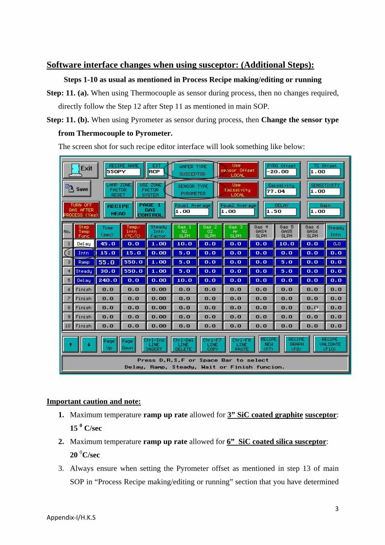
Step: 11. (a). When using Thermocouple as sensor during process, then no changes required,
directly follow the Step 12 after Step 11 as mentioned in main SOP.
Software interface changes when using susceptor: (Additional Steps): Steps 1-10 as usual as mentioned in Process Recipe making/editing or running
Step: 11. (b). When using Pyrometer as sensor during process, then Change the sensor type
from Thermocouple to Pyrometer.
The screen shot for such recipe editor interface will look something like below:
1. Maximum temperature ramp up rate allowed for
Important caution and note:
3” SiC coated graphite susceptor:
15 0
2. Maximum temperature ramp up rate allowed for
C/sec
6” SiC coated silica susceptor
20
: 0
3. Always ensure when setting the Pyrometer offset as mentioned in step 13 of main
SOP in “Process Recipe making/editing or running” section that you have determined
C/sec
4 Appendix-I/H.K.S
the offset from earlier data, which has been generated using susceptor and TC sensor
combination and NOT with wafer and TC sensor combination.
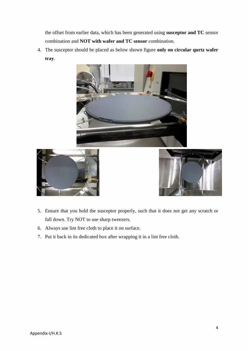
4. The susceptor should be placed as below shown figure only on circular qurtz wafer
tray.
5. Ensure that you hold the susceptor properly, such that it does not get any scratch or
fall down. Try NOT to use sharp tweezers.
6. Always use lint free cloth to place it on surface.
7. Put it back in its dedicated box after wrapping it in a lint free cloth.
1/2 Appendix-V
Appendix –V
THERMOCOUPLE INSTALLATION AND TESTING
Important Note: It has been noted that the Cantilever thermocouple may be used in place of
the pyrometer, and it should be removed for > 750 0
The tools and supplies needed to install the thermocouple are:
C process temperature (otherwise
specified) or when the pyrometer is in use. When the thermocouple is installed, its operation
should be checked before it is used for processing wafers.
small screwdriver
tweezers
small permanent magnet of any type
a pair of Latex gloves. Wear the gloves when you are handling oven quartz or
thermocouple.
The procedure for installing and checking the thermocouple is as follows:
Step: 1. Open the oven door.
Step: 2. Using tweezers, remove the quartz lock-pin from the wafer tray.
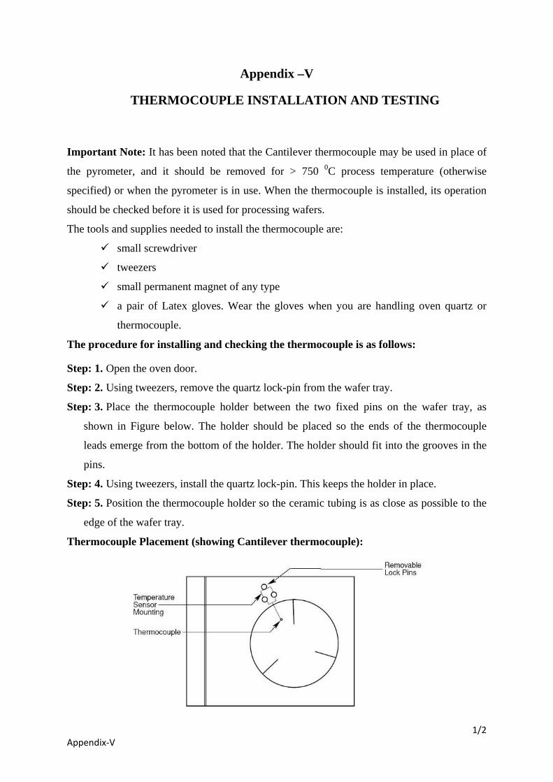
Step: 3. Place the thermocouple holder between the two fixed pins on the wafer tray, as
shown in Figure below. The holder should be placed so the ends of the thermocouple
leads emerge from the bottom of the holder. The holder should fit into the grooves in the
pins.
Step: 4. Using tweezers, install the quartz lock-pin. This keeps the holder in place.
Step: 5. Position the thermocouple holder so the ceramic tubing is as close as possible to the
edge of the wafer tray.
Thermocouple Placement (showing Cantilever thermocouple):
2/2 Appendix-V
Step: 6. Attach the thermocouple leads to the type K terminals on the inside of the oven door.
First, find which lead is attracted to a magnet. Attach this lead to the wider terminal,
labelled "AL" which also be attracted to magnet. Attach the other lead to the terminal
labelled "CH" or non attracted to magnet. (If the leads are connected in reverse, the
temperature feedback will go down when the wafer is heated.)
Step: 7. Cut off surplus lead wire, leaving a little excess in case it will be necessary to
reverse the leads.
Step: 8. Make sure that the two wires of the thermocouple are not touching anywhere than on
the tip/bead which is for touching the wafer for process.
Step: 9. Put a test wafer on the tray. Check if the backside of the wafer is down. Position the
bead so it presses against the backside of the wafer. Make sure that the bead make good
contact when wafer is placed on the tray.
Step: 10. Close the oven door.
Step: 11. Test the Thermocouple as follows: 1. Power-up the system, if it is off. 2. Go to the Diagnostics screen. 3. If the system is set up for pyrometer operation, configure for thermocouple. 4. Increase the lamp intensity to 5%. 5. Observe the temperature feedback. If the temperature indication goes down (i.e., if
temperature is negative) as heat increases, the thermocouple leads have been connected in reverse. Change the lead connections at the oven door and repeat steps 2 to 4.
6. This temperature test should be done quickly and carefully.
1/4 Appendix VII/H.K.S
Appendix – VII
QUARTZ WAFER SUPPORT TRAY REMOVAL AND INSTALLATION
Follow the following steps for Removal of Wafer tray for cleaning:
Step: 1. Open the oven door and pull it all the way out.
Note: Make sure that the oven has cooled to a temperature below 50 0
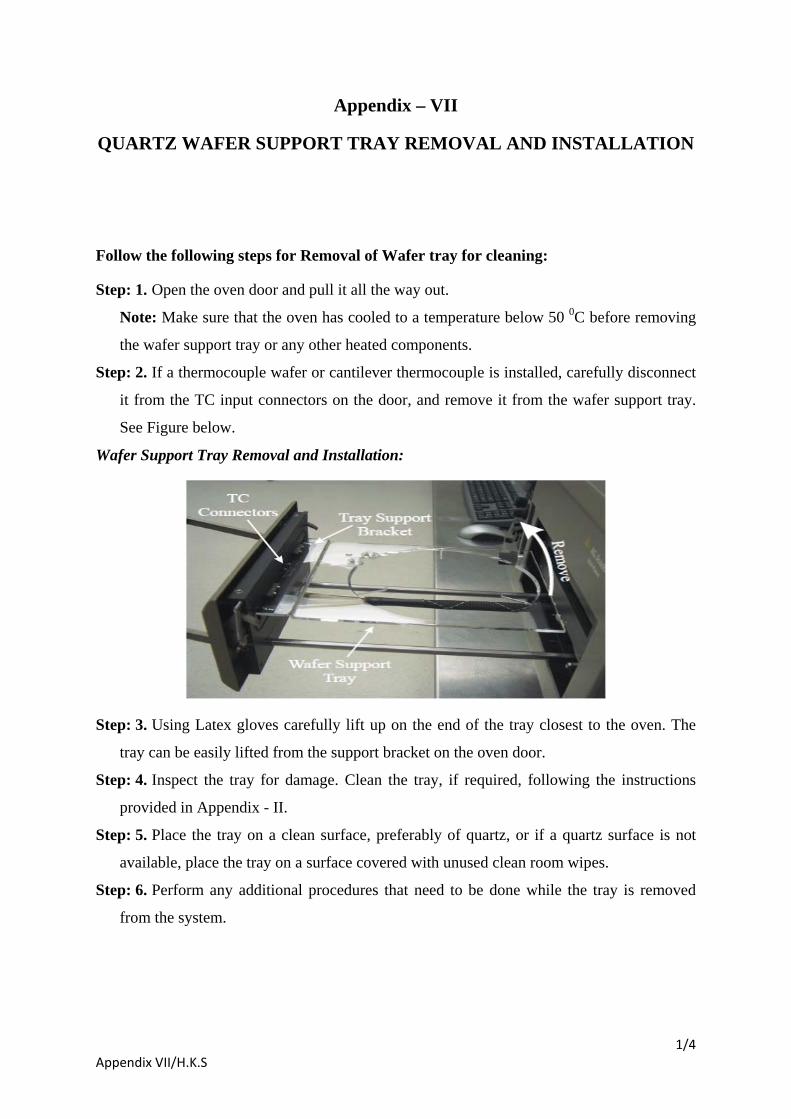
Step: 2. If a thermocouple wafer or cantilever thermocouple is installed, carefully disconnect
it from the TC input connectors on the door, and remove it from the wafer support tray.
See Figure below.
C before removing
the wafer support tray or any other heated components.
Wafer Support Tray Removal and Installation:
Step: 3. Using Latex gloves carefully lift up on the end of the tray closest to the oven. The
tray can be easily lifted from the support bracket on the oven door.
Step: 4. Inspect the tray for damage. Clean the tray, if required, following the instructions
provided in Appendix - II.
Step: 5. Place the tray on a clean surface, preferably of quartz, or if a quartz surface is not
available, place the tray on a surface covered with unused clean room wipes.
Step: 6. Perform any additional procedures that need to be done while the tray is removed
from the system.

2/4 Appendix VII/H.K.S
Follow the following steps for installation of Wafer tray after cleaning:
Step: 1. Reinstall the wafer tray with the wafer support pins up. Place the support edge of the
tray on the flange support bracket while lifting the end of the tray closest to the oven. The
tray will fit into the flange support bracket. Lower the end of the tray closest to the oven.
Step: 2. In order to achieve optimum process uniformity, it is very important that the wafer
tray be level with respect to the AccuThermo RTP oven. Use the procedure below to
ensure that the wafer support tray is properly levelled relative to the oven.
QUARTZ WAFER SUPPORT TRAY LEVELING:
Step: 3. Close the oven door to a point where the edge of the tray is flush with the oven
flange. See Figures below.
3/4 Appendix VII/H.K.S
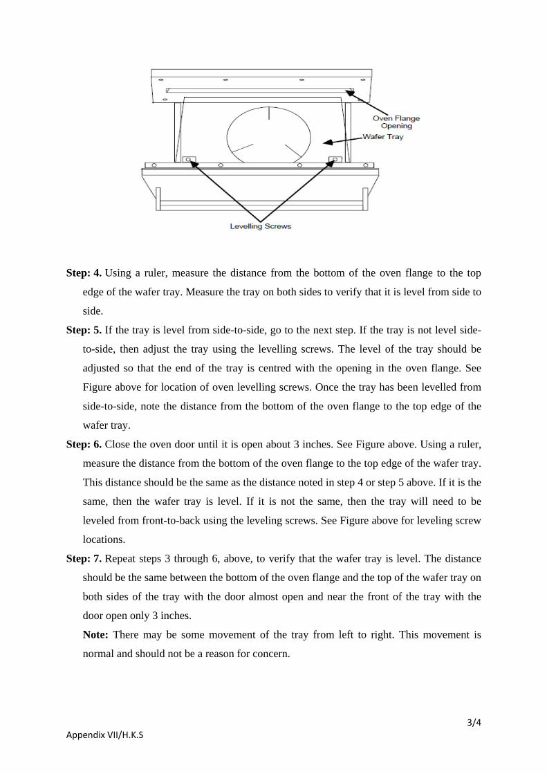
Step: 4. Using a ruler, measure the distance from the bottom of the oven flange to the top
edge of the wafer tray. Measure the tray on both sides to verify that it is level from side to
side.
Step: 5. If the tray is level from side-to-side, go to the next step. If the tray is not level side-
to-side, then adjust the tray using the levelling screws. The level of the tray should be
adjusted so that the end of the tray is centred with the opening in the oven flange. See
Figure above for location of oven levelling screws. Once the tray has been levelled from
side-to-side, note the distance from the bottom of the oven flange to the top edge of the
wafer tray.
Step: 6. Close the oven door until it is open about 3 inches. See Figure above. Using a ruler,
measure the distance from the bottom of the oven flange to the top edge of the wafer tray.
This distance should be the same as the distance noted in step 4 or step 5 above. If it is the
same, then the wafer tray is level. If it is not the same, then the tray will need to be
leveled from front-to-back using the leveling screws. See Figure above for leveling screw
locations.
Step: 7. Repeat steps 3 through 6, above, to verify that the wafer tray is level. The distance
should be the same between the bottom of the oven flange and the top of the wafer tray on
both sides of the tray with the door almost open and near the front of the tray with the
door open only 3 inches.
Note: There may be some movement of the tray from left to right. This movement is
normal and should not be a reason for concern.

4/4 Appendix VII/H.K.S
Step: 8. Place a wafer on the tray. Slowly close the door of the heating chamber. Listen for
any scraping sounds that may indicate that the quartz is not properly aligned. If you notice
any scraping sounds or resistance to door movement, realign the tray and repeat this step.
Step: 9. Reinstall the top cover on the AccuThermo RTP system if it has been removed.
Appendix - VIII
Some important points you should know
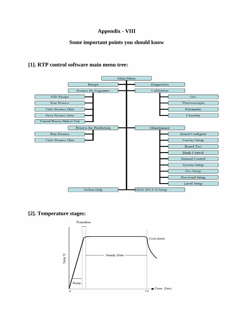
[1]. RTP control software main menu tree:
[2]. Temperature stages:
Stage: Description:
Delay: The Delay Stage is used to purge the chamber of ambient air.
Intensity: The Intensity Stage preheats the wafer to a temperature that is sufficient for the pyrometer to be usable. This is normally used if a pyrometer is to be used.
Ramp: The first Ramp of the recipe increases (Ramp Up) the temperature at a controlled rate to a desired set point. There can be subsequent Ramps in a recipe, either increasing or decreasing the temperature at a controlled rate to a desired set point. During a ramp, the intensity is adjusted to have the real-temperature follow the model-temperature.
Transition: The Transition Stage is a stage in which the temperature control changes from a controlled Ramp to a Steady-State control. This transition region starts “Delay” seconds before the programmed steady state value. At the beginning of the transition stage, the lamp intensity is reduced to make the change from Ramp to Steady-State. At the end of the transition to the Steady-State, the intensity is adjusted, usually increased, to keep the temperature from decreasing below the set point.
Steady-State: During Steady-State control, lamp intensity fluctuates to keep the temperature within the Steady-State range (±2°C). This is the Steady step programmed in the recipe.
Cool-Down: When the Steady-State portion of the cycle is completed, the cycle enters the cool-down phase. The rate of cool-down of the wafer is dependant on heat radiation from the ambient chamber temperature. At high temperatures, the wafer cools at a faster rate, initially, than it does at lower temperatures. The cool-down rate is therefore not uniform.
[3]. Psum: PSum is the integration of the intensity starting from the beginning of a ramp step and ending at the end of the following steady-state step. This, basically, measures the amount of energy applied to the wafer.
3.1 For the same kind of wafer with the same recipe, PSum with one wafer should be repeatable for another similar wafer, under perfect conditions. Factors affecting repeatability can be a dirty quartz isolation tube, a lamp failure, or an improperly functioning temperature sensor.
3.2 If the measured temperature from the sensor is higher than the real temperature of the wafer, PSum will be smaller than the average PSum.
3.3 If the measured temperature is lower than the real temperature, PSum will be larger than the average PSum.
3.4 To get the same temperature control if the quartz isolation tube is dirty, PSum will be larger than the average PSum.
3.5 To get the same temperature control if some of the lamps have degraded or are bad, PSum will be larger than the average PSum.
3.6 A recipe can have more than one ramp step followed by a steady-state step. The PSum for the first ramp/steady-state pair is called PSum1. The PSum for the second ramp/steady-state pair is called PSum2.
3.7 The benefit to using PSum1 and PSum2 is to avoid damaging any single wafer, since it will stop the process during the steady-state steps if Psum1 or Psum2 are out of range.
3.8 It is believed that only 2 PSum’s are needed. 3.9 The engineer can set parameters which use the PSum information to alarm and abort
the process if PSum1 or PSum2 exceed a specified tolerance from that of the average PSum1 or PSum2. These parameters are PSum1 Average (Limit), PSum1 Tolerance, PSum2 Average (Limit) and PSum2 Tolerance.
3.10 The average PSum is determined by averaging the PSum from several wafers. Once the average of PSum1 has been determined by the engineer, it can be entered into the PSum1 Average field in the Recipe Editor. PSum2 Average is done the same way for PSum2. PSum1 Average and PSum2 Average can be any positive value.
3.11 Therefore, the tolerance of PSum is PSum1 Tolerance or PSum2 Tolerance, which are found in the System Setup screen. By default, PSum1 Tolerance and PSum2 Tolerance are set to 20%.
3.12 The alarm can be disabled by making PSum1 Average and PSum2 Average less than 10.0.
[4]. About Thermocouple: 4.1 The AccuThermo RTP system only uses the K-type thermocouple. K-type
thermocouples are made with nickel-chromium (NiCr) for one wire and nickel-
aluminum (NiAl) for the other wire.
4.2 The NiAl lead is attracted to a magnet. Therefore, use a small magnet to determine the
proper polarity when connecting thermocouple wires to the door terminals. Wires with
the same metal alloy should be connected together.
4.3 When in use, the thermocouple is situated inside the quartz isolation tube and
positioned so that it is in contact with the wafer being processed. The thermocouple is
used typically to control process temperatures below about 800°C.
Note: Thermocouple may fuse into the wafer at temperatures above 800°C. As a result, the
thermocouple should be removed and the pyrometer should be used for temperature
measurement when the oven is to be operated at temperatures higher than 700°C.
4.4 The thermocouple assembly can be any of the following types:

Cantilever thermocouple assembly: This type is a 10-mil type K bead thermocouple
in direct contact with the backside of the wafer. The thermocouple is held against the
wafer by two spring wires that also serve as the thermocouple leads. The wires pass
through a removable T-shaped mounting piece made of quartz. See Figure below.
TC wafer assembly: This assembly is a type K chromel-alumel thermocouple, which
is cemented to a wafer. The cement used is a sodium-free ceramic cement. See Figure
below. Typically, the TC wafer is used for the calibration of the pyrometer.
4.5 The Cantilever thermocouple is used in place of the TC wafer assembly for the
measurement of oven temperature during wafer processing.
4.6 The TC wafer thermocouple is used during calibration of the pyrometer.
4.7 The two-thermocouple wires for these two thermocouple assemblies run through a
ceramic tube to K-type terminals on the inside of the oven door. The terminals run
through a gas-tight seal in the door.
Cantilever Thermocouple Assembly:
The TC wafer assembly has a thermocouple embedded in a wafer.(Thermocouple Wafer Assembly):

[5]. About Optical Pyrometer (ERP): 5.1 The Extended Range Pyrometer (ERP) is an optical pyrometer attached to the bottom
plate of the oven. Radiation from the wafer reaches the pyrometer through the bottom of
the transparent quartz isolation tube and through a small aperture in the oven floor. The
pyrometer converts detected infrared light energy to a voltage.
5.2 Optical pyrometer readings are emissivity-dependent. This means that these readings
are affected by changes in wafer backside surface colour and roughness, deposited
backside layers, or variations in substrate materials.
5.3 The ERP measures wafer temperature by detecting infrared light radiation emitted from
the wafer within a specified wavelength range. The resulting signal is adjusted to
compensate for the effects of non-wafer radiation sources.
5.4 Undesired radiation emitted from non-wafer sources must be compensated for or
filtered out in order to accurately measure wafer temperature inside an AccuThermo
RTP system heating chamber lamps and light energy emitted from the isolation tube .
5.5 During extended heating cycles, the temperature of the thermopile and AccuThermo
RTP system quartz isolation tube gradually increases.
5.6 Thermopile heating causes increased output signal voltage without a corresponding
increase in received infrared radiation.
5.7 Isolation tube heating creates an additional source of infrared emission adding to and
increasing the infrared energy being received by the pyrometer.
5.8 These phenomena both work to distort the wafer temperature measurements of the
optical pyrometer.
5.9 To eliminate the effects of thermopile heating, the ERP incorporates a water-cooling
system that maintains a steady pyrometer thermopile temperature.
5.10 To minimize the effects of quartz isolation tube heating, the quartz isolation tube is
cooled with compressed nitrogen or clean dry air (CDA). This maintains the temperature
of the tube within a specified range but does not entirely prevent the temperature
measurement distorting effects of isolation tube heating.
5.11 Additional cancellation of the effects of isolation tube heating is enabled by the dual
range infrared detection capability designed into the extended range pyrometer.
5.12 Specifically, the ERP incorporates both a Wafer-Sensing Pyrometer (referred to as the
Wafer Pyrometer) and a Tube-Sensing Pyrometer (referred to as the Tube Pyrometer).
5.13 Each of these pyrometers incorporates a different proprietary infrared band pass filter.
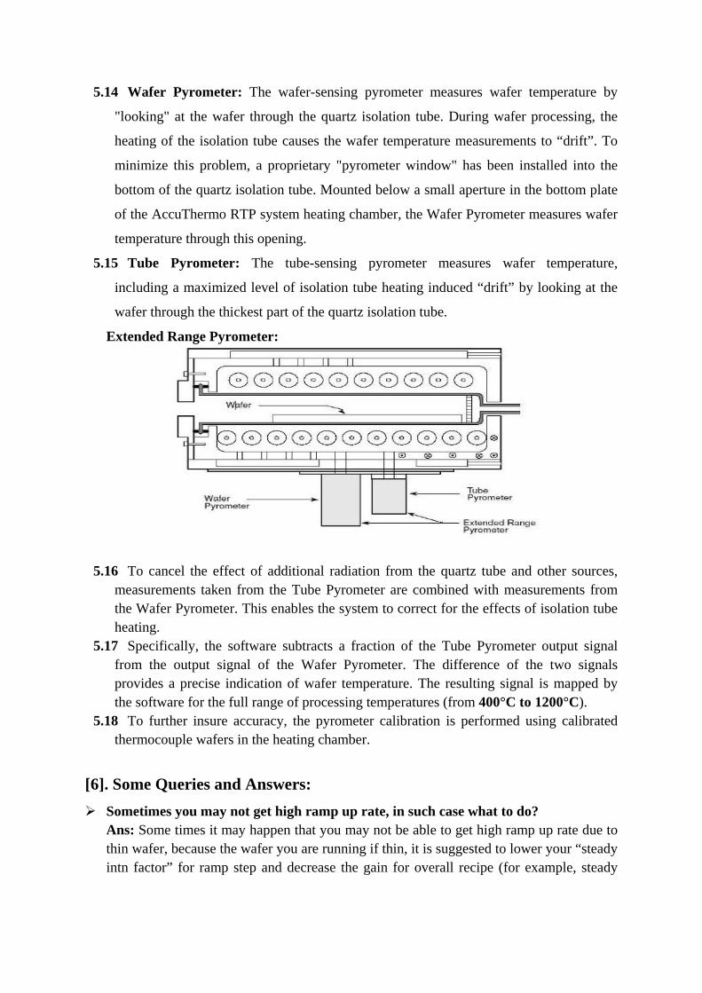
5.14 Wafer Pyrometer: The wafer-sensing pyrometer measures wafer temperature by
"looking" at the wafer through the quartz isolation tube. During wafer processing, the
heating of the isolation tube causes the wafer temperature measurements to “drift”. To
minimize this problem, a proprietary "pyrometer window" has been installed into the
bottom of the quartz isolation tube. Mounted below a small aperture in the bottom plate
of the AccuThermo RTP system heating chamber, the Wafer Pyrometer measures wafer
temperature through this opening.
5.15 Tube Pyrometer: The tube-sensing pyrometer measures wafer temperature,
including a maximized level of isolation tube heating induced “drift” by looking at the
wafer through the thickest part of the quartz isolation tube.
Extended Range Pyrometer:
5.16 To cancel the effect of additional radiation from the quartz tube and other sources, measurements taken from the Tube Pyrometer are combined with measurements from the Wafer Pyrometer. This enables the system to correct for the effects of isolation tube heating.
5.17 Specifically, the software subtracts a fraction of the Tube Pyrometer output signal from the output signal of the Wafer Pyrometer. The difference of the two signals provides a precise indication of wafer temperature. The resulting signal is mapped by the software for the full range of processing temperatures (from 400°C to 1200°C).
5.18 To further insure accuracy, the pyrometer calibration is performed using calibrated thermocouple wafers in the heating chamber.
[6]. Some Queries and Answers: Sometimes you may not get high ramp up rate, in such case what to do?
Ans: Some times it may happen that you may not be able to get high ramp up rate due to thin wafer, because the wafer you are running if thin, it is suggested to lower your “steady intn factor” for ramp step and decrease the gain for overall recipe (for example, steady

intn factor for ramp = .80 and gain = .7). Try this and see how it goes. If it does not succeed at first time, try to lower one or both values again.
Can I have control for lowering my cooling rate? Ans: If you want to cool off slower for your wafer process then you can add another “ramp” step after your 400C steady step. In the ramp step you can specify the cooling rate. For example, after 400C steady step, you can add ramp step with 1. Time = 30 second, 2. Temp= 100C. This way the software will control your ramp down rate and in this case it is 10 C/s (300 C/30 S = 10 C/s).

Appendix IX
Weekly tool cleaning Procedure for RTP tool
1. Use Lint free cloth and IPA only for cleaning purpose. 2. Wipe thoroughly the top side of the instrument and attached Monitor and
Keyboard by lint free cloth wet with IPA. 3. Always use hand gloves for cleaning/using the instrument. 4. You can use Nitrogen gun with slow flow rate for cleaning the restricted
region by blowing the dust particles out with nitrogen gas (GN2) flow. 5. After cleaning, keep all the accessories and tools at proper place and keep
the system region neat and clean.