performance comparison of two low-co2 emission solar
TRANSCRIPT

Applied Energy 155 (2015) 740–752
Contents lists available at ScienceDirect
Applied Energy
journal homepage: www.elsevier .com/ locate/apenergy
Performance comparison of two low-CO2 emission solar/methanolhybrid combined cycle power systems
http://dx.doi.org/10.1016/j.apenergy.2015.06.0520306-2619/� 2015 Elsevier Ltd. All rights reserved.
⇑ Corresponding author. Tel.: +86 10 82543030; fax: +86 10 82543151.E-mail address: [email protected] (N. Zhang).
Yuanyuan Li a, Na Zhang b,⇑, Noam Lior c
a Key Laboratory of Condition Monitoring and Control for Power Plant Equipment (North China Electric Power University), Ministry of Education, Beijing 102206, Chinab Institute of Engineering Thermophysics, Chinese Academy of Sciences, Beijing 100190, Chinac Department of Mechanical Engineering and Applied Mechanics, University of Pennsylvania, Philadelphia, PA 19104-6315, USA
h i g h l i g h t s
� Two novel solar hybrid combined cycle systems have been proposed and analyzed.� The power systems integrate solar-driven thermo-chemical conversion and CO2 capture.� Exergy efficiency of about 55% and specific CO2 emissions of 34 g/kW h are predicted.� Systems CO2 emissions are 36.8% lower compared to a combined cycle with CO2 capture.� The fossil fuel demand is �30% lower with a solar share of �20%.
a r t i c l e i n f o
Article history:Received 29 December 2014Received in revised form 8 June 2015Accepted 17 June 2015
Keywords:Hybrid power systemsLow/middle temperature solar heatMethanol conversion to syngasThermo-chemical integrationLow CO2 emissionPre-combustion decarbonization
a b s t r a c t
Two novel hybrid combined cycle power systems that use solar heat and methanol, and integrate CO2
capture, are proposed and analyzed, one based on solar-driven methanol decomposition and the otheron solar-driven methanol reforming. The high methanol conversion rates at relatively low temperaturesoffer the advantage of using the solar heat at only 200–300 �C to drive the syngas production byendothermic methanol conversions and its conversion to chemical energy. Pre-combustion decarboniza-tion is employed to produce CO2-free fuel from the fully converted syngas, which is then burned toproduce heat at the high temperature for power generation in the proposed advanced combined cyclesystems. To improve efficiency, the systems’ configurations were based on the principle of cascade useof multiple heat sources of different temperatures. The thermodynamic performance of the hybrid powersystems at its design point is simulated and evaluated. The results show that the hybrid systems canattain an exergy efficiency of about 55%, and specific CO2 emissions as low as 34 g/kW h. Compared toa gas/steam combined cycle with flue gas CO2 capture, the proposed solar-assisted system CO2 emissionsare 36.8% lower, and a fossil fuel saving ratio of �30% is achievable with a solar thermal share of �20%.The system integration predicts high efficiency conversion of solar heat and low-energy-penalty CO2 cap-ture, with the additional advantage that solar heat is at relatively low temperature where its collection ischeaper and simpler. The systems’ components are robust and in common use, and the proposedhybridization approach can be also used with similar benefits by replacing the solar heat input with otherlow heat sources, and the system integration achieves the dual-purpose of clean use of fossil fuel andhigh-efficiency conversion of solar heat at the same time.
� 2015 Elsevier Ltd. All rights reserved.
1. Introduction
The hybrid power system proposed in this paper has two energyinput sources: methanol and solar heat. Methanol is considered tobe a fuel alternative in both transportation and power generation
sectors and is already used in that way to limited extent. Being liq-uid at atmospheric conditions, it is easier and cheaper to transportand store than natural gas. Methanol production on large scale isgenerally based on the chemical synthesis of syngas mostly pro-duced either from natural gas reforming or coal gasification. Theabundance of coal in China makes coal gasification especially suit-able for China’s needs. The integration of a coal gasifier with a com-bined cycle and methanol synthesis, ‘‘coal based poly-generation’’,provides a promising technology for power generation and
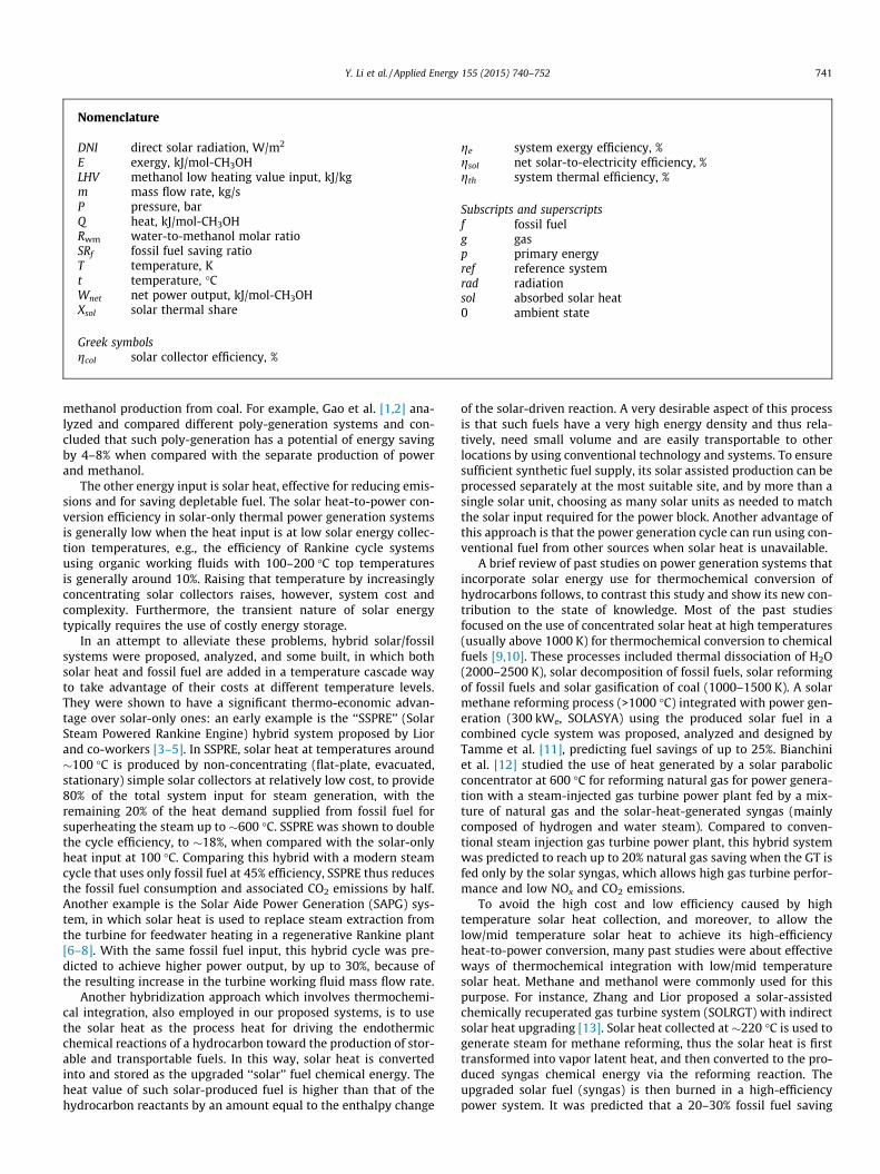
Nomenclature
DNI direct solar radiation, W/m2
E exergy, kJ/mol-CH3OHLHV methanol low heating value input, kJ/kgm mass flow rate, kg/sP pressure, barQ heat, kJ/mol-CH3OHRwm water-to-methanol molar ratioSRf fossil fuel saving ratioT temperature, Kt temperature, �CWnet net power output, kJ/mol-CH3OHXsol solar thermal share
Greek symbolsgcol solar collector efficiency, %
ge system exergy efficiency, %gsol net solar-to-electricity efficiency, %gth system thermal efficiency, %
Subscripts and superscriptsf fossil fuelg gasp primary energyref reference systemrad radiationsol absorbed solar heat0 ambient state
Y. Li et al. / Applied Energy 155 (2015) 740–752 741
methanol production from coal. For example, Gao et al. [1,2] ana-lyzed and compared different poly-generation systems and con-cluded that such poly-generation has a potential of energy savingby 4–8% when compared with the separate production of powerand methanol.
The other energy input is solar heat, effective for reducing emis-sions and for saving depletable fuel. The solar heat-to-power con-version efficiency in solar-only thermal power generation systemsis generally low when the heat input is at low solar energy collec-tion temperatures, e.g., the efficiency of Rankine cycle systemsusing organic working fluids with 100–200 �C top temperaturesis generally around 10%. Raising that temperature by increasinglyconcentrating solar collectors raises, however, system cost andcomplexity. Furthermore, the transient nature of solar energytypically requires the use of costly energy storage.
In an attempt to alleviate these problems, hybrid solar/fossilsystems were proposed, analyzed, and some built, in which bothsolar heat and fossil fuel are added in a temperature cascade wayto take advantage of their costs at different temperature levels.They were shown to have a significant thermo-economic advan-tage over solar-only ones: an early example is the ‘‘SSPRE’’ (SolarSteam Powered Rankine Engine) hybrid system proposed by Liorand co-workers [3–5]. In SSPRE, solar heat at temperatures around�100 �C is produced by non-concentrating (flat-plate, evacuated,stationary) simple solar collectors at relatively low cost, to provide80% of the total system input for steam generation, with theremaining 20% of the heat demand supplied from fossil fuel forsuperheating the steam up to �600 �C. SSPRE was shown to doublethe cycle efficiency, to �18%, when compared with the solar-onlyheat input at 100 �C. Comparing this hybrid with a modern steamcycle that uses only fossil fuel at 45% efficiency, SSPRE thus reducesthe fossil fuel consumption and associated CO2 emissions by half.Another example is the Solar Aide Power Generation (SAPG) sys-tem, in which solar heat is used to replace steam extraction fromthe turbine for feedwater heating in a regenerative Rankine plant[6–8]. With the same fossil fuel input, this hybrid cycle was pre-dicted to achieve higher power output, by up to 30%, because ofthe resulting increase in the turbine working fluid mass flow rate.
Another hybridization approach which involves thermochemi-cal integration, also employed in our proposed systems, is to usethe solar heat as the process heat for driving the endothermicchemical reactions of a hydrocarbon toward the production of stor-able and transportable fuels. In this way, solar heat is convertedinto and stored as the upgraded ‘‘solar’’ fuel chemical energy. Theheat value of such solar-produced fuel is higher than that of thehydrocarbon reactants by an amount equal to the enthalpy change
of the solar-driven reaction. A very desirable aspect of this processis that such fuels have a very high energy density and thus rela-tively, need small volume and are easily transportable to otherlocations by using conventional technology and systems. To ensuresufficient synthetic fuel supply, its solar assisted production can beprocessed separately at the most suitable site, and by more than asingle solar unit, choosing as many solar units as needed to matchthe solar input required for the power block. Another advantage ofthis approach is that the power generation cycle can run using con-ventional fuel from other sources when solar heat is unavailable.
A brief review of past studies on power generation systems thatincorporate solar energy use for thermochemical conversion ofhydrocarbons follows, to contrast this study and show its new con-tribution to the state of knowledge. Most of the past studiesfocused on the use of concentrated solar heat at high temperatures(usually above 1000 K) for thermochemical conversion to chemicalfuels [9,10]. These processes included thermal dissociation of H2O(2000–2500 K), solar decomposition of fossil fuels, solar reformingof fossil fuels and solar gasification of coal (1000–1500 K). A solarmethane reforming process (>1000 �C) integrated with power gen-eration (300 kWe, SOLASYA) using the produced solar fuel in acombined cycle system was proposed, analyzed and designed byTamme et al. [11], predicting fuel savings of up to 25%. Bianchiniet al. [12] studied the use of heat generated by a solar parabolicconcentrator at 600 �C for reforming natural gas for power genera-tion with a steam-injected gas turbine power plant fed by a mix-ture of natural gas and the solar-heat-generated syngas (mainlycomposed of hydrogen and water steam). Compared to conven-tional steam injection gas turbine power plant, this hybrid systemwas predicted to reach up to 20% natural gas saving when the GT isfed only by the solar syngas, which allows high gas turbine perfor-mance and low NOx and CO2 emissions.
To avoid the high cost and low efficiency caused by hightemperature solar heat collection, and moreover, to allow thelow/mid temperature solar heat to achieve its high-efficiencyheat-to-power conversion, many past studies were about effectiveways of thermochemical integration with low/mid temperaturesolar heat. Methane and methanol were commonly used for thispurpose. For instance, Zhang and Lior proposed a solar-assistedchemically recuperated gas turbine system (SOLRGT) with indirectsolar heat upgrading [13]. Solar heat collected at �220 �C is used togenerate steam for methane reforming, thus the solar heat is firsttransformed into vapor latent heat, and then converted to the pro-duced syngas chemical energy via the reforming reaction. Theupgraded solar fuel (syngas) is then burned in a high-efficiencypower system. It was predicted that a 20–30% fossil fuel saving

742 Y. Li et al. / Applied Energy 155 (2015) 740–752
ratio can be achieved compared with a conventional chemicallyrecuperated gas turbine system (CRGT) without solar heat contri-bution. Li et al. [14] proposed and analyzed a hybrid system(LEHSOLCC) that incorporates solar-driven methane/steammembrane reforming. The reformer is integrated with a hydrogenseparation membrane, enabling continuous removal of hydrogenfrom the retentate (reaction) zone, and thus shifting the reactionto the product side. The impermeable CO2-rich syngas is collectedfrom the bottom of the reaction zone. Nearly complete CH4 conver-sion can be achieved at a reforming temperature of 550 �C. Adesign-point performance analysis shows that the system attainsa net exergy efficiency of 58% and specific CO2 emissions of25 g/kW h with 91% CO2 capture ratio. A fossil fuel saving ratioof 31% is achievable with a solar thermal share of about 28%.
Methanol is endothermically reactive at relatively low-temperatures. For example, methanol-steam reforming andmethanol decomposition are highly endothermic and can achieve>90% conversion into H2-rich syngas at around 250 �C. Hong andco-workers proposed a combined cycle (called Solar CC) that inte-grates mid-temperature solar thermal energy with methanoldecomposition [15]. Rather than fueling the power block directly,the solar heat is used at low/mid temperatures to drive theendothermic methanol decomposition, thus upgraded to chemicalenergy of the produced syngas and attained its high efficiencyconversion to power in a combined cycle system consequently.This concept mitigates both solar energy related limitations: it usessolar heat at low- to mid-level temperatures, where its collection ischeaper and simpler, and its use is for producing syngas with itshigh chemical storage capability that also creates physicalindependence of the solar block from the power system. The solarheat share of the total heat input was only 18%, the CO2 was notcaptured, and the Solar CC system has ended up with a CO2
emission of about 300 g/kW h.Zhao and Yue [16] proposed and analyzed a conceptual
advanced humid air turbine cycle (HAT). Driven by solar heat col-lected by a solar parabolic collector at 200–300 �C, methanoldecomposition reaction is conducted to produce CO and H2
enriched syngas. With the turbine inlet temperature (TIT) of about1000–1300 �C, the obtained results show that the exergy efficiencyof the cycle is higher by nearly 6%-points than that of the conven-tional HAT cycle.
Re-emphasizing, using solar heat at lower temperatures, asproposed in this study, offers more economical employment ofsolar energy, with the associated benefits of increased substitutionof renewable energy for fuel and lower CO2 emissions.
Another important advantage of the systems proposed in thisstudy is that, as shown further below, they emit very smallamounts of CO2 with a very small energy efficiency penalty.Conventional techniques for CO2 capture typically impose about10%-points penalty to the system overall efficiency [17,18], sothe reduction of CO2 emissions would result in a commensuratereduction in overall efficiency losses due to its capture, and animportant objective is to find ways to reduce these emissions bya combination of replacing some fraction of the fossil fuel by solarenergy, and by efficiently integrating capture of the remaining CO2
into the power system. As an example, Zhang et al. proposed a zeroCO2 emission solar hybrid gas turbine (ZE-SOLRGT) systememploying oxy-fuel combustion [19–21].
Another family of hybrid cycles with reduced CO2 emission arethe solar-driven chemical-looping combustion cycles. Hong et al.proposed a solar hybrid combined cycle system incorporatingmethanol-fuel chemical-looping combustion and use of solar heatat about 450–500 �C for Ni-based redox and 150–300 �C for redoxbetween FeO and Fe2O3, in which solar-driven endothermic reduc-tion of NiO [22] or Fe2O3 [23] by methanol is carried out. The CO2
can be easily separated from the produced vapor by condensation,
with low energy penalty. Taking the FeO/Fe2O3 basedmethanol-fueled chemical looping combustion as an example, asupplementary combustor is used to reach a gas turbine inlet tem-perature (TIT) of 1400 �C, and the resulting system exergy efficiencywas predicted to be as high as 58.4% with a CO2 separation of 55%.
In the above-reviewed solar hybrid systems that do not imple-ment CO2 capture, the system CO2 emission decreases proportion-ally to the reduction of fossil fuel consumption, but they stillproduce CO2 emission of 300–350 g/kW h due to the large energyinput fraction from fossil fuel. Since the thermo-chemical upgrad-ing of solar heat generates syngas from the hydrocarbon fuel, thenovel systems of this study offer the best opportunity foremploying pre-combustion decarbonization to the syngas and con-sequently for reducing CO2 emission beyond what is achieved byreducing the hydrocarbon fuel just by its partial replacement withsolar energy. An important innovation in this proposal and study isthat, as described in more detail below (Sections 2–4), in additionto the hybridization with solar thermal energy at relatively lowtemperatures, the systems also employ pre-combustiondecarbonization to the produced syngas, thus achieving thedual-purpose of clean use of fossil fuel and high-efficiency conver-sion of solar heat at the same time. The typical hybrid systems withsolar thermochemical integration are summarized in Table 1,which demonstrates that the proposed systems of this studyindeed have such quantitative advantages over others proposedand studied in the past.
To summarize the introduction, this paper is a proposal andanalysis of two novel low-CO2-emission solar hybrid combinedcycle systems based on solar-driven methanol decompositionand reforming, respectively. Pre-combustion decarbonization isalso employed to the fully converted syngas that is then burnedto produce heat at the high temperature for power generation inan advanced combined cycle system.
The two systems are configured with particular attention on thethermal match of internal heat recuperation with both steam gen-eration and endothermic chemical conversion. The thermody-namic performance is simulated with ASPEN PLUS software [25],assuming steady state.
The system performance is compared with a gas-steamcombined cycle system with CO2 capture from its exhaust gas(CC-Post), which has no solar assistance.
As introduced above, and demonstrated in Sections 4 and 5below, such integration of solar heat with fossil fuelthermo-chemical conversion contributes to the clean use of fossilfuel and high efficiency and relatively low cost conversion of solarheat in (1) elevation of the fuel heating value and the overall poweroutput, (2) high efficiency conversion of solar heat, (3) lowenergy-penalty CO2 capture integrated with energy conversion,and (4) offering the option of storing high energy density syngasinstead of storing solar heat.
2. System configuration description
Following the thermodynamic principle of temperature-cascadeuse of multiple heat sources, and integration of CO2 capture withenergy conversion, two hybrid power systems are proposed in thisstudy, based on solar-heat driven methanol decomposition andreforming, respectively.
2.1. The proposed low CO2 emission solar hybrid combined cycle systemwith methanol decomposition and a shift reaction (LESOLCC-DCP)system
Methanol is endothermically decomposed by heat input over acatalyst at temperatures of about 200–300 �C, and produces amixture of H2 and CO:
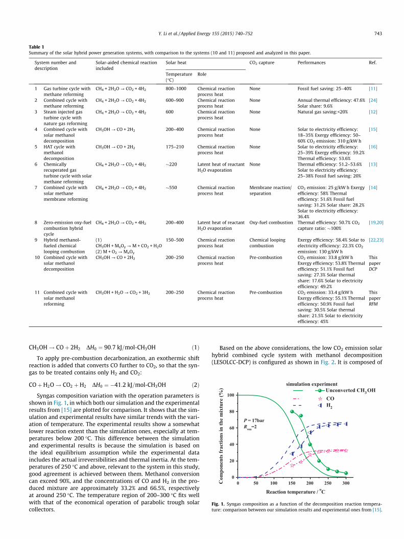
Table 1Summary of the solar hybrid power generation systems, with comparison to the systems (10 and 11) proposed and analyzed in this paper.
System number anddescription
Solar-aided chemical reactionincluded
Solar heat CO2 capture Performances Ref.
Temperature(�C)
Role
1 Gas turbine cycle withmethane reforming
CH4 + 2H2O ? CO2 + 4H2 800–1000 Chemical reactionprocess heat
None Fossil fuel saving: 25–40% [11]
2 Combined cycle withmethane reforming
CH4 + 2H2O ? CO2 + 4H2 600–900 Chemical reactionprocess heat
None Annual thermal efficiency: 47.6%Solar share: 9.6%
[24]
3 Steam injected gasturbine cycle withnature gas reforming
CH4 + 2H2O ? CO2 + 4H2 600 Chemical reactionprocess heat
None Natural gas saving:<20% [12]
4 Combined cycle withsolar methanoldecomposition
CH3OH ? CO + 2H2 200–400 Chemical reactionprocess heat
None Solar to electricity efficiency:18–35% Exergy efficiency: 50–60% CO2 emission: 310 g/kW h
[15]
5 HAT cycle withmethanoldecomposition
CH3OH ? CO + 2H2 175–210 Chemical reactionprocess heat
None Solar to electricity efficiency:25–39% Exergy efficiency: 59.2%Thermal efficiency: 53.6%
[16]
6 Chemicallyrecuperated gasturbine cycle with solarmethane reforming
CH4 + 2H2O ? CO2 + 4H2 �220 Latent heat of reactantH2O evaporation
None Thermal efficiency: 51.2–53.6%Solar to electricity efficiency:25–38% Fossil fuel saving: 20%
[13]
7 Combined cycle withsolar methanemembrane reforming
CH4 + 2H2O ? CO2 + 4H2 �550 Chemical reactionprocess heat
Membrane reaction/separation
CO2 emission: 25 g/kW h Exergyefficiency: 58% Thermalefficiency: 51.6% Fossil fuelsaving: 31.2% Solar share: 28.2%Solar to electricity efficiency:36.4%
[14]
8 Zero-emission oxy-fuelcombustion hybridcycle
CH4 + 2H2O ? CO2 + 4H2 200–400 Latent heat of reactantH2O evaporation
Oxy-fuel combustion Thermal efficiency: 50.7% CO2
capture ratio: �100%[19,20]
9 Hybrid methanol-fueled chemicallooping combustion
(1)CH3OH + MxOy ? M + CO2 + H2O(2) M + O2 ? MxOy
150–500 Chemical reactionprocess heat
Chemical loopingcombustion
Exergy efficiency: 58.4% Solar toelectricity efficiency: 22.3% CO2
emission: 130 g/kW h
[22,23]
10 Combined cycle withsolar methanoldecomposition
CH3OH ? CO + 2H2 200–250 Chemical reactionprocess heat
Pre-combustion CO2 emission: 33.8 g/kW hExergy efficiency: 53.8% Thermalefficiency: 51.1% Fossil fuelsaving: 27.3% Solar thermalshare: 17.6% Solar to electricityefficiency: 49.2%
ThispaperDCP
11 Combined cycle withsolar methanolreforming
CH3OH + H2O ? CO2 + 3H2 200–250 Chemical reactionprocess heat
Pre-combustion CO2 emission: 33.4 g/kW hExergy efficiency: 55.1% Thermalefficiency: 50.9% Fossil fuelsaving: 30.5% Solar thermalshare: 21.5% Solar to electricityefficiency: 45%
ThispaperRFM
0 50 100 150 200 250 3000
20
40
60
80
100
experimentUnconverted CH3OHCOH2
Com
pone
nts f
ract
ions
in th
e m
ixtu
re (%
)
Reaction temperature / oC
simulation
P = 17barRwm=2
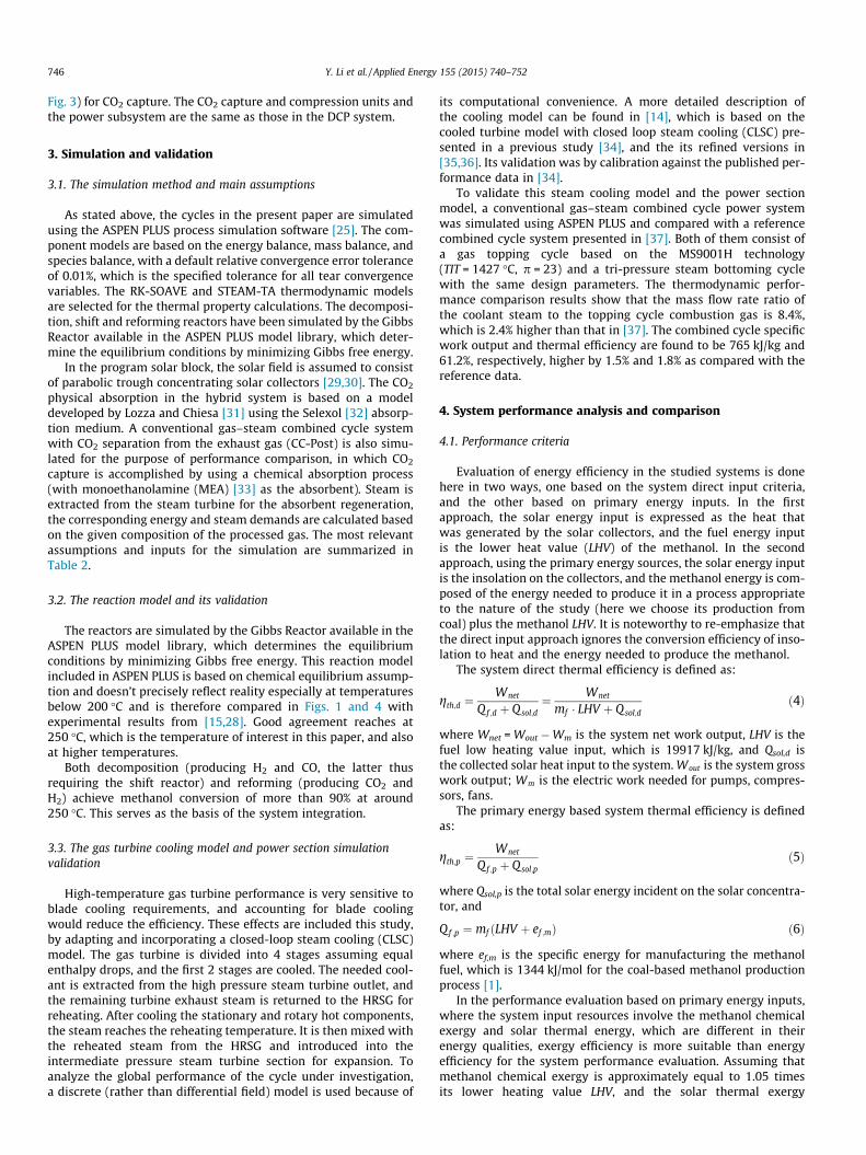
Fig. 1. Syngas composition as a function of the decomposition reaction tempera-ture: comparison between our simulation results and experimental ones from [15].
Y. Li et al. / Applied Energy 155 (2015) 740–752 743
CH3OH! COþ 2H2 DH0 ¼ 90:7 kJ=mol-CH3OH ð1Þ
To apply pre-combustion decarbonization, an exothermic shiftreaction is added that converts CO further to CO2, so that the syn-gas to be treated contains only H2 and CO2:
COþH2O! CO2 þH2 DH0 ¼ �41:2 kJ=mol-CH3OH ð2Þ
Syngas composition variation with the operation parameters isshown in Fig. 1, in which both our simulation and the experimentalresults from [15] are plotted for comparison. It shows that the sim-ulation and experimental results have similar trends with the vari-ation of temperature. The experimental results show a somewhatlower reaction extent than the simulation ones, especially at tem-peratures below 200 �C. This difference between the simulationand experimental results is because the simulation is based onthe ideal equilibrium assumption while the experimental dataincludes the actual irreversibilities and thermal inertia. At the tem-peratures of 250 �C and above, relevant to the system in this study,good agreement is achieved between them. Methanol conversioncan exceed 90%, and the concentrations of CO and H2 in the pro-duced mixture are approximately 33.2% and 66.5%, respectivelyat around 250 �C. The temperature region of 200–300 �C fits wellwith that of the economical operation of parabolic trough solarcollectors.
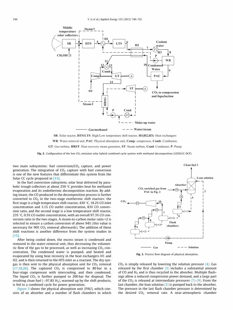
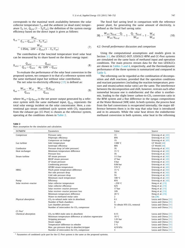
Based on the above considerations, the low CO2 emission solarhybrid combined cycle system with methanol decomposition(LESOLCC-DCP) is configured as shown in Fig. 2. It is composed of
Middletemperature
solar collectors
CH3OH
SR LTSHTS
1
H2
HR
SG
H3
e
e
P Cond
Make-up water
Comp
ST
Comb
CO2 to compression and liquefaction
2
3
4 5H1
9
1011
Air
6
78
12 13
14
GT
Gas/methanol Water/steam
Steam
Steam
WRP
PAU
Condensed Water
Coolantwater
SR: Solar reactor, HTS/LTS: High/Low temperature shift reactor, H1(H2,H3): Heat exchangers
WR: Water-removal unit, PAU: Physical absorption unit, Comp: compressor, Comb: Combustor,
GT: Gas turbine, HRST: Heat recovery steam generator, ST: Steam turbine, Cond: Condenser, P: Pump
Fig. 2. Configuration of the low CO2 emission solar hybrid combined cycle system with methanol decomposition (LESOLCC-DCP).
Flashchambers
Absorber
Pump
CO2 enriched gas from PAU in Fig. 2
Clean fuel 3
CO2
Lean solution
4
5
6
10
Gas Solution
2
7
8
9
Fig. 3. Process flow diagram of physical absorption.
744 Y. Li et al. / Applied Energy 155 (2015) 740–752
two main subsystems: fuel conversion/CO2 capture, and powergeneration. The integration of CO2 capture with fuel conversionis one of the new features that differentiate this system from theSolar CC cycle proposed in [15].
In the fuel conversion subsystem, solar heat delivered by para-bolic trough collectors at about 250 �C provides heat for methanolevaporation and its endothermic decomposition reaction. By add-ing steam, the CO produced in the decomposition process is furtherconverted to CO2 in the two-stage exothermic shift reactors: thefirst stage is a high temperature shift reactor, 430 �C, 18.2% CO inletconcentration and 3.1% CO outlet concentration, 83% CO conver-sion ratio, and the second stage is a low temperature shift reactor,235 �C, 0.5% CO outlet concentration, with an overall 97.3% CO con-version ratio in the two stages. A steam-to-carbon molar ratio >2 isselected to ensure a carbon conversion of above 94% (this value isnecessary for 90% CO2 removal afterwards). The addition of theseshift reactions is another difference from the system studies in[15].
After being cooled down, the excess steam is condensed andremoved in the water-removal unit, thus decreasing the volumet-ric flow of the gas to be processed, as well as increasing CO2 con-centration. The condensed water is pumped, and heated andevaporated by using heat recovery in the heat exchangers H1 andH2, and is then returned to the HTS inlet as a reactant. The dry syn-gas is then sent to the physical absorption unit for CO2 removal[17,18,26]. The captured CO2 is compressed to 80 bar in afour-stage compressor with intercooling, and then condensed.The liquid CO2 is further pumped to 200 bar for disposal. Theresulting clean fuel (�97.8% H2), warmed up by the shift products,is fed to a combined cycle for power generation.
Figure 3 shows the physical absorption unit (PAU), which con-sists of an absorber and a number of flash chambers in which
CO2 is simply released by lowering the solution pressure (4). Gasreleased by the first chamber (5) includes a substantial amountof CO and H2 and is thus recycled to the absorber. Multiple flash-ings allow a reduced compression power demand, and a large partof the CO2 is released at intermediate pressures (7)–(9). From thelast chamber, the lean solution (2) is pumped back to the absorber.The pressure in the last flash chamber pressure is determined bythe desired CO2 removal rate. A near-atmospheric chamber
Y. Li et al. / Applied Energy 155 (2015) 740–752 745
pressure allows a 79.6% CO2 separation. To obtain a CO2 removalrate of 95%, a pressure as low as 0.25 bar would be necessary.
The internal heat recuperation, however, can produce only 40%vof the total shift-needed steam. The remainder of the needed steam(60%v of the total) is extracted from the heat recovery steam gen-erator (HRSG, stream 2) in the power sector, rather than generatedby the solar heat collection, because otherwise the large volume ofsteam generation would have led to a significant enlargement ofthe solar collector area and consequent increase in system cost,by about 36.9% and 21.1%, respectively.
The power subsystem is configured as a conventional combinedcycle with a topping Brayton cycle and a bottoming tri-pressureRankine cycle.
0 50 100 150 200 250 3000
20
40
60
80
100
simulation experiment
Com
pone
nts f
ract
ions
in th
e m
ixtu
re(%
)
Reactiom temperature / oC
Unconverted CH3OHCO2H2
CO
P = 17barRwm=2
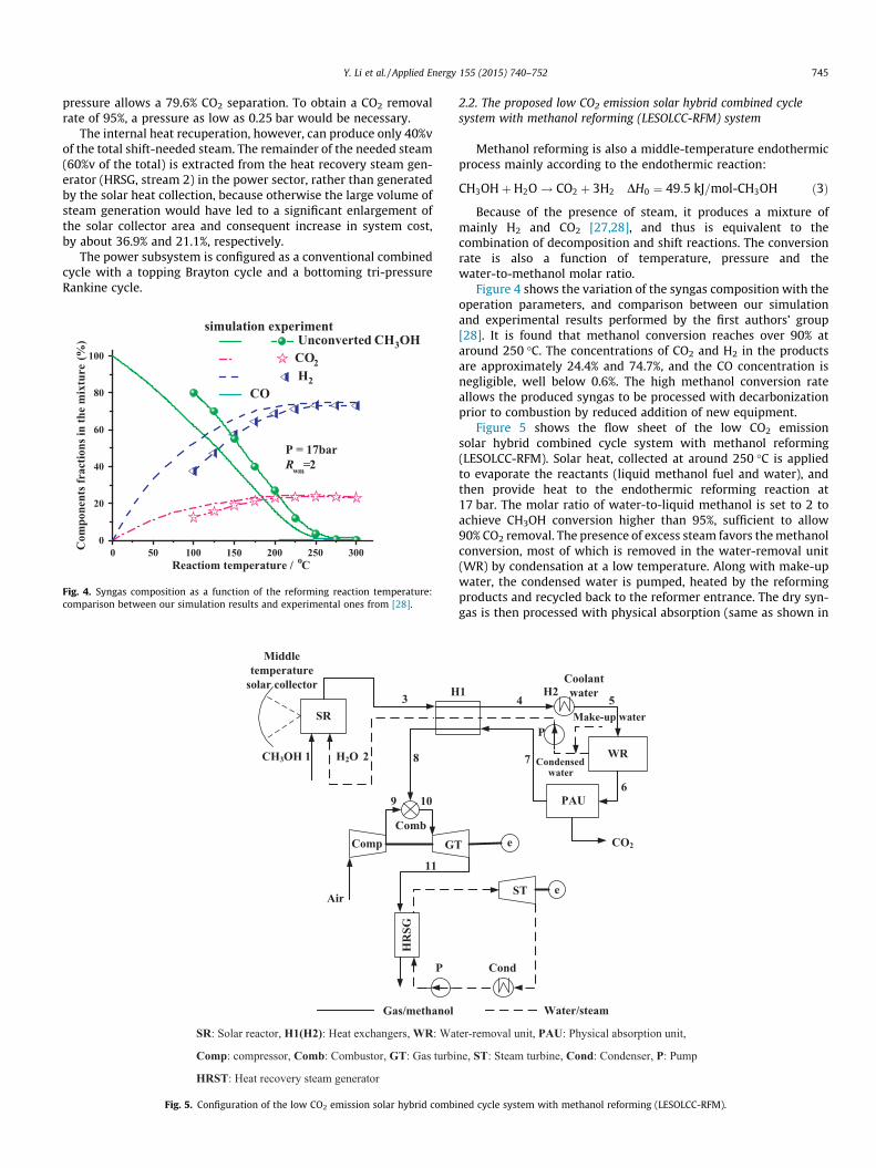
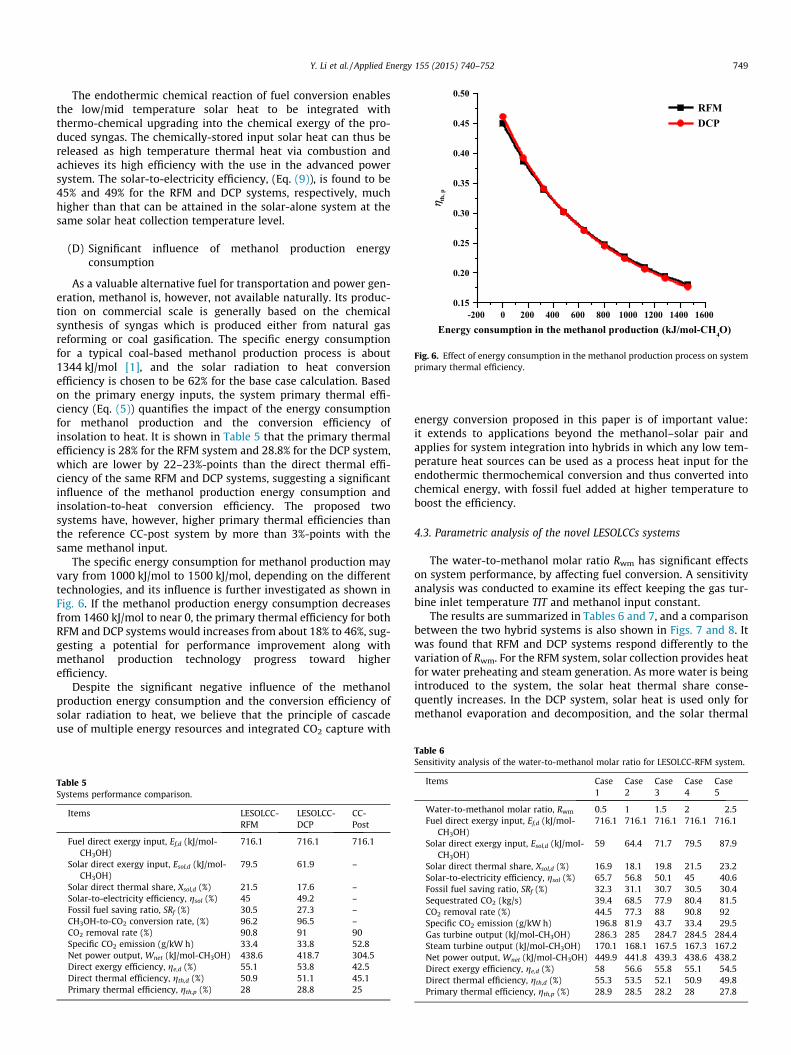
Fig. 4. Syngas composition as a function of the reforming reaction temperature:comparison between our simulation results and experimental ones from [28].
Middletemperature
solar collector
CH3OH
SR
1
H
HR
SG
P
CompComb
Air
9 01
11
GT
2
3
8H2O
Gas/methanol
SR: Solar reactor, H1(H2): Heat exchangers, WR: Wa
Comp: compressor, Comb: Combustor, GT: Gas turbi
HRST: Heat recovery steam generator
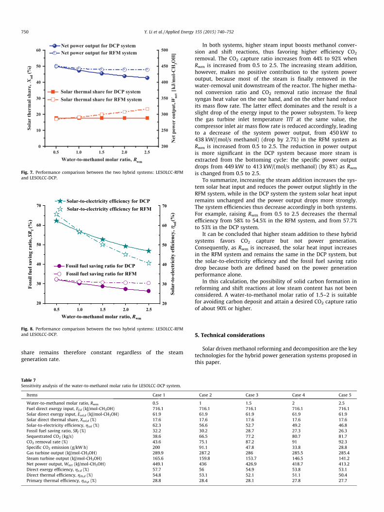
Fig. 5. Configuration of the low CO2 emission solar hybrid combi
2.2. The proposed low CO2 emission solar hybrid combined cyclesystem with methanol reforming (LESOLCC-RFM) system
Methanol reforming is also a middle-temperature endothermicprocess mainly according to the endothermic reaction:
CH3OHþH2O! CO2 þ 3H2 DH0 ¼ 49:5 kJ=mol-CH3OH ð3Þ
Because of the presence of steam, it produces a mixture ofmainly H2 and CO2 [27,28], and thus is equivalent to thecombination of decomposition and shift reactions. The conversionrate is also a function of temperature, pressure and thewater-to-methanol molar ratio.
Figure 4 shows the variation of the syngas composition with theoperation parameters, and comparison between our simulationand experimental results performed by the first authors’ group[28]. It is found that methanol conversion reaches over 90% ataround 250 �C. The concentrations of CO2 and H2 in the productsare approximately 24.4% and 74.7%, and the CO concentration isnegligible, well below 0.6%. The high methanol conversion rateallows the produced syngas to be processed with decarbonizationprior to combustion by reduced addition of new equipment.
Figure 5 shows the flow sheet of the low CO2 emissionsolar hybrid combined cycle system with methanol reforming(LESOLCC-RFM). Solar heat, collected at around 250 �C is appliedto evaporate the reactants (liquid methanol fuel and water), andthen provide heat to the endothermic reforming reaction at17 bar. The molar ratio of water-to-liquid methanol is set to 2 toachieve CH3OH conversion higher than 95%, sufficient to allow90% CO2 removal. The presence of excess steam favors the methanolconversion, most of which is removed in the water-removal unit(WR) by condensation at a low temperature. Along with make-upwater, the condensed water is pumped, heated by the reformingproducts and recycled back to the reformer entrance. The dry syn-gas is then processed with physical absorption (same as shown in
1
WR
e
e
Cond
Make-up water
ST
CO2
4 5
6
7
Water/steam
H2
PAU
Coolantwater
Condensedwater
P
ter-removal unit, PAU: Physical absorption unit,
ne, ST: Steam turbine, Cond: Condenser, P: Pump
ned cycle system with methanol reforming (LESOLCC-RFM).
746 Y. Li et al. / Applied Energy 155 (2015) 740–752
Fig. 3) for CO2 capture. The CO2 capture and compression units andthe power subsystem are the same as those in the DCP system.
3. Simulation and validation
3.1. The simulation method and main assumptions
As stated above, the cycles in the present paper are simulatedusing the ASPEN PLUS process simulation software [25]. The com-ponent models are based on the energy balance, mass balance, andspecies balance, with a default relative convergence error toleranceof 0.01%, which is the specified tolerance for all tear convergencevariables. The RK-SOAVE and STEAM-TA thermodynamic modelsare selected for the thermal property calculations. The decomposi-tion, shift and reforming reactors have been simulated by the GibbsReactor available in the ASPEN PLUS model library, which deter-mine the equilibrium conditions by minimizing Gibbs free energy.
In the program solar block, the solar field is assumed to consistof parabolic trough concentrating solar collectors [29,30]. The CO2
physical absorption in the hybrid system is based on a modeldeveloped by Lozza and Chiesa [31] using the Selexol [32] absorp-tion medium. A conventional gas–steam combined cycle systemwith CO2 separation from the exhaust gas (CC-Post) is also simu-lated for the purpose of performance comparison, in which CO2
capture is accomplished by using a chemical absorption process(with monoethanolamine (MEA) [33] as the absorbent). Steam isextracted from the steam turbine for the absorbent regeneration,the corresponding energy and steam demands are calculated basedon the given composition of the processed gas. The most relevantassumptions and inputs for the simulation are summarized inTable 2.
3.2. The reaction model and its validation
The reactors are simulated by the Gibbs Reactor available in theASPEN PLUS model library, which determines the equilibriumconditions by minimizing Gibbs free energy. This reaction modelincluded in ASPEN PLUS is based on chemical equilibrium assump-tion and doesn’t precisely reflect reality especially at temperaturesbelow 200 �C and is therefore compared in Figs. 1 and 4 withexperimental results from [15,28]. Good agreement reaches at250 �C, which is the temperature of interest in this paper, and alsoat higher temperatures.
Both decomposition (producing H2 and CO, the latter thusrequiring the shift reactor) and reforming (producing CO2 andH2) achieve methanol conversion of more than 90% at around250 �C. This serves as the basis of the system integration.
3.3. The gas turbine cooling model and power section simulationvalidation
High-temperature gas turbine performance is very sensitive toblade cooling requirements, and accounting for blade coolingwould reduce the efficiency. These effects are included this study,by adapting and incorporating a closed-loop steam cooling (CLSC)model. The gas turbine is divided into 4 stages assuming equalenthalpy drops, and the first 2 stages are cooled. The needed cool-ant is extracted from the high pressure steam turbine outlet, andthe remaining turbine exhaust steam is returned to the HRSG forreheating. After cooling the stationary and rotary hot components,the steam reaches the reheating temperature. It is then mixed withthe reheated steam from the HRSG and introduced into theintermediate pressure steam turbine section for expansion. Toanalyze the global performance of the cycle under investigation,a discrete (rather than differential field) model is used because of
its computational convenience. A more detailed description ofthe cooling model can be found in [14], which is based on thecooled turbine model with closed loop steam cooling (CLSC) pre-sented in a previous study [34], and the its refined versions in[35,36]. Its validation was by calibration against the published per-formance data in [34].
To validate this steam cooling model and the power sectionmodel, a conventional gas–steam combined cycle power systemwas simulated using ASPEN PLUS and compared with a referencecombined cycle system presented in [37]. Both of them consist ofa gas topping cycle based on the MS9001H technology(TIT = 1427 �C, p = 23) and a tri-pressure steam bottoming cyclewith the same design parameters. The thermodynamic perfor-mance comparison results show that the mass flow rate ratio ofthe coolant steam to the topping cycle combustion gas is 8.4%,which is 2.4% higher than that in [37]. The combined cycle specificwork output and thermal efficiency are found to be 765 kJ/kg and61.2%, respectively, higher by 1.5% and 1.8% as compared with thereference data.
4. System performance analysis and comparison
4.1. Performance criteria
Evaluation of energy efficiency in the studied systems is donehere in two ways, one based on the system direct input criteria,and the other based on primary energy inputs. In the firstapproach, the solar energy input is expressed as the heat thatwas generated by the solar collectors, and the fuel energy inputis the lower heat value (LHV) of the methanol. In the secondapproach, using the primary energy sources, the solar energy inputis the insolation on the collectors, and the methanol energy is com-posed of the energy needed to produce it in a process appropriateto the nature of the study (here we choose its production fromcoal) plus the methanol LHV. It is noteworthy to re-emphasize thatthe direct input approach ignores the conversion efficiency of inso-lation to heat and the energy needed to produce the methanol.
The system direct thermal efficiency is defined as:
gth;d ¼Wnet
Q f ;d þ Q sol;d¼ Wnet
mf � LHV þ Q sol;dð4Þ
where Wnet = Wout �Wm is the system net work output, LHV is thefuel low heating value input, which is 19917 kJ/kg, and Qsol,d isthe collected solar heat input to the system. Wout is the system grosswork output; Wm is the electric work needed for pumps, compres-sors, fans.
The primary energy based system thermal efficiency is definedas:
gth;p ¼Wnet
Q f ;p þ Q sol;pð5Þ
where Qsol,p is the total solar energy incident on the solar concentra-tor, and
Qf ;p ¼ mf ðLHV þ ef ;mÞ ð6Þ
where ef,m is the specific energy for manufacturing the methanolfuel, which is 1344 kJ/mol for the coal-based methanol productionprocess [1].
In the performance evaluation based on primary energy inputs,where the system input resources involve the methanol chemicalexergy and solar thermal energy, which are different in theirenergy qualities, exergy efficiency is more suitable than energyefficiency for the system performance evaluation. Assuming thatmethanol chemical exergy is approximately equal to 1.05 timesits lower heating value LHV, and the solar thermal exergy
Y. Li et al. / Applied Energy 155 (2015) 740–752 747
corresponds to the maximal work availability between the solarcollector temperature Tsol and the ambient (or dead state) temper-ature T0, i.e., Qsol,d (1 � T0/Tsol), the definition of the system exergyefficiency based on the direct input is given as follows:
ge;d ¼Wnet
Ef ;d þ Q sol;dð1� T0=TsolÞ
¼ Wnet
1:05mf � LHV þ Q sol;dð1� T0=TsolÞð7Þ
The contribution of the low/mid temperature level solar heatcan be measured by its share based on the direct energy input:
Xsol;d ¼Q sol;d
Q f ;d þ Q sol;d¼ Q sol;d
mf � LHV þ Qsol;dð8Þ
To evaluate the performance of the solar heat conversion in theproposed system, we compare it to that of a reference system withthe same methanol input but without solar contribution.
The net solar-to-electricity efficiency [15] is defined as:
gsol ¼Wnet �Wref
Qsol;p¼
Wnet � Q f gth;ref
Qsol;pð9Þ
where Wref = Qf�gth,ref is the net power output generated by a refer-ence system with the same methanol input, Qsol,p represents thetotal solar energy incident on the solar concentrator. Here, a con-ventional gas–steam combined cycle system with CO2 separationfrom the exhaust gas (CC-Post) is chosen as the reference system,operating at the conditions shown in Table 2.
Table 2Main assumption for the simulation and calculation.
DCP&RFM Parameters
Compressor Pressure ratioPolytropic efficiencyCompressor air leakage
Gas turbine Inlet temperatureIsentropic efficiency
Combustor Pressure drop (of inlet pressure)Heat exchanger Minimum temperature difference
Pressure lossSteam turbine HP steam pressure
RH/IP steam pressureLP steam pressureCondensing pressureHP/RH steam temperature
HRSG Pinch-point temperature differenceHot side pressure dropCold side pressure dropMinimum stack temperature
Pump EfficiencySolar receiver–reactor Solar collector temperature
Solar collector efficiencySolar receiver–reactor pressureSolar receiver–reactor pressure lossMinimum temperature differenceWater-to-methanol molar ratio
Physical absorption CO2-to-selexol mole ratio in absorbentNumber of flash chambersLast chamber pressureNumber of intercoolers for CO2 compressor
CC-Posta
Chemical absorption CO2-to-MEA mole ratio in absorbentMinimum temperature difference at solution regenStripping pressureSteam supplyTemperature difference in reboilerMax. gas pressure drop in absorber/stripperNumber of intercoolers for CO2 compressor
a Parameters of combined cycle part for the CC-Post system is the same as the propo
The fossil fuel saving level in comparison with the referencepower plant, for generating the same amount of electricity, isdefined as the fossil fuel saving ratio:
SRf ¼Wnet=gth;ref � Q f
Wnet=gth;ref¼ 1�
Q f � gth;ref
Wnet¼ 1�Wref
Wnetð10Þ
4.2. Overall performance discussion and comparison
Using the computational assumptions and models given inSection 3.1, the LESOLCC-DCP, LESOLCC-RFM and CC-Post systemsare simulated on the same basis of methanol input and operationconditions. The main process stream data for the two LESOLCCsare shown in Tables 3 and 4, respectively, and the thermodynamicperformance of the three systems is summarized and compared inTable 5.
The reforming can be regarded as the combination of decompo-sition and shift reactions, provided that the operation conditionsand reactant parameters (including the reaction temperature, pres-sure and steam/carbon molar ratio) are the same. The interferencebetween the decomposition and shift, however, restrain each othersomewhat because one is endothermic and the other is exother-mic, leading to the slight lower carbon-to-CO2 conversion ratio inthe RFM system and a fine difference in the syngas compositionsat the Water Removal (WR) inlet. In both systems, the process heatfrom the fuel conversions is recuperated internally; the major dif-ference between them is in the way that solar heat is introducedand in its amounts. While the solar heat drives the endothermicmethanol conversion in both systems, solar heat in the reforming
Value Source
15 Ertesvåg et al. [43]89% Ertesvåg et al. [43]1% Ertesvåg et al. [43]1308 �C GT World [44]88% GT World [44]3% Ertesvåg et al. [43]15 �C Ertesvåg et al. [43]3% Ertesvåg et al. [43]111 bar Ertesvåg et al. [43]27 bar Ertesvåg et al. [43]4 bar Ertesvåg et al. [43]0.06 bar Ertesvåg et al. [43]570 �C Ertesvåg et al. [43]15 �C Ertesvåg et al. [43]3% Ertesvåg et al. [43]5% Ertesvåg et al. [43]100 �C Ertesvåg et al. [43]85% Ertesvåg et al. [43]�250 �C Hong et al. [15]62% Hong et al. [15]17 bar Hong et al. [15]10% Hong et al. [15]20 �C Hong et al. [15]2 Liu [28]0.1 Lozza and Chiesa [31]4 Lozza and Chiesa [31]To obtain 95% CO2 removal Lozza and Chiesa [31]3 Lozza and Chiesa [31]
0.15 Lozza and Chiesa [31]erator 10 �C Lozza and Chiesa [31]
1.01 bar Lozza and Chiesa [31]3 bar Lozza and Chiesa [31]5 �C Lozza and Chiesa [31]4/10 kPa Lozza and Chiesa [31]3 Lozza and Chiesa [31]
sed systems.

Table 3Main stream states of the LESOLCC-DCP system (points refer to Fig. 2).
Point t (�C) P (bar) m (kg/s) VF Percent molar composition (%)
N2 O2 CH3OH H2O CO2 CO H2 Ar
1 25 18.8 32 0.0 1002 207.1 18 19.8 100 1003 207.1 18 16.2 100 1004 430 17.7 68 100 0.005 23.1 16.9 3.1 56.95 207.5 17.6 68 100 0.005 23.1 16.9 3.1 56.96 235 17.2 68 100 0.2 20.8 19.4 0.5 59.17 121.6 17.1 68 90.2 0.2 20.8 19.4 0.5 59.18 30 17.1 68 79.2 0.2 20.8 19.4 0.5 59.19 30 17.1 49.4 100 0.2 24.4 0.7 74.7
10 30 17.1 9.1 100 0.3 1.6 0.9 97.211 220 17 9.1 100 0.3 1.6 0.9 97.212 408.3 15 619.6 100 77.3 20.7 1.01 0.03 0.9213 1308 14.7 628.6 100 72.1 12.8 13.8 0.4 0.914 639.2 1.05 628.6 100 72.1 12.8 13.8 0.4 0.9
Table 4Main stream states of the LESOLCC-RFM system (points refer to Fig. 5).
Point t (�C) P (bar) m (kg/s) VF Percent molar composition (%)
N2 O2 CH3OH H2O CO2 CO H2 Ar
1 25 18.8 32 0.0 1002 27 18.8 36 0.0 1003 250 17.6 68 100 0.1 20.8 19.3 0.6 59.14 121 17.3 68 90.0 0.1 20.8 19.3 0.6 59.15 30 17.1 68 79.2 0.1 20.8 19.3 0.6 59.16 30 17.1 49.3 100 0.2 24.4 0.8 74.77 30 17.1 9.1 100 0.2 1.6 1 97.28 230 17 9.1 100 0.2 1.6 1 97.29 408.3 15 619.8 100 77.3 20.7 1.01 0.03 0.92
10 1308 14.7 628.9 100 72.1 12.8 13.8 0.4 0.911 639.2 1.05 628.9 100 72.1 12.8 13.8 0.4 0.9
748 Y. Li et al. / Applied Energy 155 (2015) 740–752
system is used also for steam generation; and in the decompositionsystem, the additional steam for methanol conversion is extractedfrom the HRSG in the power subsystem. The solar thermal shareswere therefore indeed found to be different, 21.5% in the RFMsystem and 17.6% in the DCP one.
We conclude from Table 5 that the integration of solar heat andCO2 capture with fuel conversion affects the system performancein the following ways:
(A) Augments the system power output and reduced CO2 emis-sion for the same fuel input.
The solar heat stored as the syngas chemical exergy contributesto increased power output. The RFM system with the most solarheat input has the highest power output of 439 kW/(mol/s metha-nol), followed by the DCP system of 419 kW, higher by 44% and37.5%, respectively, as compared with the reference CC-Post sys-tem without solar assistance.
The significant augmentation of the power output also leads tothe much higher exergy and energy efficiencies of both hybrid sys-tems, by about 29.6% and 10.9% as compared with that of the ref-erence CC-post system.
Partial replacement of fossil fuel with solar heat contributes notonly to fossil fuel saving, but also to CO2 emissions reduction forthe same amount of electricity generation. The fossil fuel savingratio is found to be 30.5% for the RFM system, and 27.3% for theDCP system. The difference comes from the different solar heatinput. With the same CO2 capture ratio, both hybrid systems havespecific CO2 emission of about 33–34 g/kW h that are much lower,by about 36%, than that of the CC-Post system.
(B) Low energy-penalty CO2 capture
CO2 capture is energy-consuming, typically leading to a systemefficiency drop up to 10%-points [17,18]. The energy penalties eval-uated by thermal efficiency drops are calculated for the three sys-tems. The efficiency penalty is defined here as the amount bywhich thermal efficiency decreases for the RFM, DCP and CC-Postsystem when compared with the respective reference systemswithout CO2 capture.
In the CC-Post system, chemical absorption is applied to sepa-rate CO2 from the flue gases, and large gas quantities have to betreated because CO2 is diluted by the nitrogen in the combustionair. Steam extraction from the bottoming cycle provides theneeded heat for the absorbent regeneration. The bottoming cyclepower output drops accordingly and the efficiency penalty in thissystem is found to be 11%-points.
In contrast, CO2 capture is introduced in both of our hybrid sys-tems at the point with the highest CO2 concentration and the low-est gas flow rate. Specifically, in the RFM system, production of asyngas with high CO2 concentration owing to fuel conversion witha high carbon conversion ratio is thus very favorable toenergy-efficient pre-combustion decarbonization for CO2 capture.The efficiency penalty for CO2 capture in the RFM system wasfound to be only 4%-points. In the DCP system, decomposition pro-duces CO- and H2-enriched syngas, but the shift reactors intro-duced increase the energy consumption, resulting in a thermalefficiency penalty of 6.6%-points.
(C) High efficiency conversion of low/mid temperature solarheat
-200 0 200 400 600 800 1000 1200 1400 16000.15
0.20
0.25
0.30
0.35
0.40
0.45
0.50RFM
DCP
η th, p
Energy consumption in the methanol production (kJ/mol-CH4O)
Fig. 6. Effect of energy consumption in the methanol production process on systemprimary thermal efficiency.
Y. Li et al. / Applied Energy 155 (2015) 740–752 749
The endothermic chemical reaction of fuel conversion enablesthe low/mid temperature solar heat to be integrated withthermo-chemical upgrading into the chemical exergy of the pro-duced syngas. The chemically-stored input solar heat can thus bereleased as high temperature thermal heat via combustion andachieves its high efficiency with the use in the advanced powersystem. The solar-to-electricity efficiency, (Eq. (9)), is found to be45% and 49% for the RFM and DCP systems, respectively, muchhigher than that can be attained in the solar-alone system at thesame solar heat collection temperature level.
(D) Significant influence of methanol production energyconsumption
As a valuable alternative fuel for transportation and power gen-eration, methanol is, however, not available naturally. Its produc-tion on commercial scale is generally based on the chemicalsynthesis of syngas which is produced either from natural gasreforming or coal gasification. The specific energy consumptionfor a typical coal-based methanol production process is about1344 kJ/mol [1], and the solar radiation to heat conversionefficiency is chosen to be 62% for the base case calculation. Basedon the primary energy inputs, the system primary thermal effi-ciency (Eq. (5)) quantifies the impact of the energy consumptionfor methanol production and the conversion efficiency ofinsolation to heat. It is shown in Table 5 that the primary thermalefficiency is 28% for the RFM system and 28.8% for the DCP system,which are lower by 22–23%-points than the direct thermal effi-ciency of the same RFM and DCP systems, suggesting a significantinfluence of the methanol production energy consumption andinsolation-to-heat conversion efficiency. The proposed twosystems have, however, higher primary thermal efficiencies thanthe reference CC-post system by more than 3%-points with thesame methanol input.
The specific energy consumption for methanol production mayvary from 1000 kJ/mol to 1500 kJ/mol, depending on the differenttechnologies, and its influence is further investigated as shown inFig. 6. If the methanol production energy consumption decreasesfrom 1460 kJ/mol to near 0, the primary thermal efficiency for bothRFM and DCP systems would increases from about 18% to 46%, sug-gesting a potential for performance improvement along withmethanol production technology progress toward higherefficiency.
Despite the significant negative influence of the methanolproduction energy consumption and the conversion efficiency ofsolar radiation to heat, we believe that the principle of cascadeuse of multiple energy resources and integrated CO2 capture with
Table 5Systems performance comparison.
Items LESOLCC-RFM
LESOLCC-DCP
CC-Post
Fuel direct exergy input, Ef,d (kJ/mol-CH3OH)
716.1 716.1 716.1
Solar direct exergy input, Esol,d (kJ/mol-CH3OH)
79.5 61.9 –
Solar direct thermal share, Xsol,d (%) 21.5 17.6 –Solar-to-electricity efficiency, gsol (%) 45 49.2 –Fossil fuel saving ratio, SRf (%) 30.5 27.3 –CH3OH-to-CO2 conversion rate, (%) 96.2 96.5 –CO2 removal rate (%) 90.8 91 90Specific CO2 emission (g/kW h) 33.4 33.8 52.8Net power output, Wnet (kJ/mol-CH3OH) 438.6 418.7 304.5Direct exergy efficiency, ge,d (%) 55.1 53.8 42.5Direct thermal efficiency, gth,d (%) 50.9 51.1 45.1Primary thermal efficiency, gth,p (%) 28 28.8 25
energy conversion proposed in this paper is of important value:it extends to applications beyond the methanol–solar pair andapplies for system integration into hybrids in which any low tem-perature heat sources can be used as a process heat input for theendothermic thermochemical conversion and thus converted intochemical energy, with fossil fuel added at higher temperature toboost the efficiency.
4.3. Parametric analysis of the novel LESOLCCs systems
The water-to-methanol molar ratio Rwm has significant effectson system performance, by affecting fuel conversion. A sensitivityanalysis was conducted to examine its effect keeping the gas tur-bine inlet temperature TIT and methanol input constant.
The results are summarized in Tables 6 and 7, and a comparisonbetween the two hybrid systems is also shown in Figs. 7 and 8. Itwas found that RFM and DCP systems respond differently to thevariation of Rwm. For the RFM system, solar collection provides heatfor water preheating and steam generation. As more water is beingintroduced to the system, the solar heat thermal share conse-quently increases. In the DCP system, solar heat is used only formethanol evaporation and decomposition, and the solar thermal
Table 6Sensitivity analysis of the water-to-methanol molar ratio for LESOLCC-RFM system.
Items Case1
Case2
Case3
Case4
Case5
Water-to-methanol molar ratio, Rwm 0.5 1 1.5 2 2.5Fuel direct exergy input, Ef,d (kJ/mol-
CH3OH)716.1 716.1 716.1 716.1 716.1
Solar direct exergy input, Esol,d (kJ/mol-CH3OH)
59 64.4 71.7 79.5 87.9
Solar direct thermal share, Xsol,d (%) 16.9 18.1 19.8 21.5 23.2Solar-to-electricity efficiency, gsol (%) 65.7 56.8 50.1 45 40.6Fossil fuel saving ratio, SRf (%) 32.3 31.1 30.7 30.5 30.4Sequestrated CO2 (kg/s) 39.4 68.5 77.9 80.4 81.5CO2 removal rate (%) 44.5 77.3 88 90.8 92Specific CO2 emission (g/kW h) 196.8 81.9 43.7 33.4 29.5Gas turbine output (kJ/mol-CH3OH) 286.3 285 284.7 284.5 284.4Steam turbine output (kJ/mol-CH3OH) 170.1 168.1 167.5 167.3 167.2Net power output, Wnet (kJ/mol-CH3OH) 449.9 441.8 439.3 438.6 438.2Direct exergy efficiency, ge,d (%) 58 56.6 55.8 55.1 54.5Direct thermal efficiency, gth,d (%) 55.3 53.5 52.1 50.9 49.8Primary thermal efficiency, gth,p (%) 28.9 28.5 28.2 28 27.8
0.5 1.0 1.5 2.0 2.50
10
20
30
40
50
60
Sola
r th
erm
al sh
are,
Xso
l (%
)
Water-to-methanol molar ratio, Rwm
Solar thermal share for DCP systemSolar thermal share for RFM system
200
250
300
350
400
450
500
Net
pow
er o
utpu
t, Wne
t [k
J/m
ol-C
H3O
H]
Net power output for DCP system Net power output for RFM system
Fig. 7. Performance comparison between the two hybrid systems: LESOLCC-RFMand LESOLCC-DCP.
0.5 1.0 1.5 2.0 2.520
30
40
50
60
70
Water-to-methanol molar ratio, Rwm
Foss
il fu
el sa
ving
rat
io, SR
f (%
)
Fossil fuel saving ratio for DCP Fossil fuel saving ratio for RFM
20
30
40
50
60
70
Sola
r-to
-ele
ctri
city
eff
icie
ncy,
ηso
l (%)
Solar-to-electricity efficiency for DCP Solar-to-electricity efficiency for RFM
Fig. 8. Performance comparison between the two hybrid systems: LESOLCC-RFMand LESOLCC-DCP.
750 Y. Li et al. / Applied Energy 155 (2015) 740–752
share remains therefore constant regardless of the steamgeneration rate.
Table 7Sensitivity analysis of the water-to-methanol molar ratio for LESOLCC-DCP system.
Items Case 1
Water-to-methanol molar ratio, Rwm 0.5Fuel direct exergy input, Ef,d (kJ/mol-CH3OH) 716.1Solar direct exergy input, Esol,d (kJ/mol-CH3OH) 61.9Solar direct thermal share, Xsol,d (%) 17.6Solar-to-electricity efficiency, gsol (%) 62.3Fossil fuel saving ratio, SRf (%) 32.2Sequestrated CO2 (kg/s) 38.6CO2 removal rate (%) 43.6Specific CO2 emission (g/kW h) 200Gas turbine output (kJ/mol-CH3OH) 289.9Steam turbine output (kJ/mol-CH3OH) 165.6Net power output, Wnet (kJ/mol-CH3OH) 449.1Direct exergy efficiency, ge,d (%) 57.7Direct thermal efficiency, gth,d (%) 54.8Primary thermal efficiency, gth,p (%) 28.8
In both systems, higher steam input boosts methanol conver-sion and shift reactions, thus favoring higher efficiency CO2
removal. The CO2 capture ratio increases from 44% to 92% whenRwm is increased from 0.5 to 2.5. The increasing steam addition,however, makes no positive contribution to the system poweroutput, because most of the steam is finally removed in thewater-removal unit downstream of the reactor. The higher metha-nol conversion ratio and CO2 removal ratio increase the finalsyngas heat value on the one hand, and on the other hand reduceits mass flow rate. The latter effect dominates and the result is aslight drop of the energy input to the power subsystem. To keepthe gas turbine inlet temperature TIT at the same value, thecompressor inlet air mass flow rate is reduced accordingly, leadingto a decrease of the system power output, from 450 kW to438 kW/(mol/s methanol) (drop by 2.7%) in the RFM system asRwm is increased from 0.5 to 2.5. The reduction in power outputis more significant in the DCP system because more steam isextracted from the bottoming cycle: the specific power outputdrops from 449 kW to 413 kW/(mol/s methanol) (by 8%) as Rwm
is changed from 0.5 to 2.5.To summarize, increasing the steam addition increases the sys-
tem solar heat input and reduces the power output slightly in theRFM system, while in the DCP system the system solar heat inputremains unchanged and the power output drops more strongly.The system efficiencies thus decrease accordingly in both systems.For example, raising Rwm from 0.5 to 2.5 decreases the thermalefficiency from 58% to 54.5% in the RFM system, and from 57.7%to 53% in the DCP system.
It can be concluded that higher steam addition to these hybridsystems favors CO2 capture but not power generation.Consequently, as Rwm is increased, the solar heat input increasesin the RFM system and remains the same in the DCP system, butthe solar-to-electricity efficiency and the fossil fuel saving ratiodrop because both are defined based on the power generationperformance alone.
In this calculation, the possibility of solid carbon formation inreforming and shift reactions at low steam content has not beenconsidered. A water-to-methanol molar ratio of 1.5–2 is suitablefor avoiding carbon deposit and attain a desired CO2 capture ratioof about 90% or higher.
5. Technical considerations
Solar driven methanol reforming and decomposition are the keytechnologies for the hybrid power generation systems proposed inthis paper.
Case 2 Case 3 Case 4 Case 5
1 1.5 2 2.5716.1 716.1 716.1 716.161.9 61.9 61.9 61.917.6 17.6 17.6 17.656.6 52.7 49.2 46.830.2 28.7 27.3 26.366.5 77.2 80.7 81.775.1 87.2 91 92.391.1 47.8 33.8 28.8287.2 286 285.5 285.4159.8 153.7 146.5 141.2436 426.9 418.7 413.256 54.9 53.8 53.153.1 52.1 51.1 50.428.4 28.1 27.8 27.7
Y. Li et al. / Applied Energy 155 (2015) 740–752 751
Both reforming and decomposition are well establishedtechnologies in the chemical industry. With proper catalysts, theytake place at a reaction temperature of 200–300 �C, much lowerthan that required for methane conversion.
The commercially mature parabolic trough solar concentratingcollectors [3] fit well with this temperature range application.
The methanol to syngas conversion is well understood frommany studies that have been conducted, numerically and experi-mentally, on catalysts, reaction mechanism, kinetics, and develop-ment of reactors. For example, Nakagaki developed a designmethod for methanol reformers by examining the reaction rateswith Cu–Zn catalyst and reforming performance of a tube reactor[38]. Patel established a mechanistic kinetic model for methanolsteam reforming over a Cu/ZnO/Al2O3 catalyst, to predict the pro-duction rates of hydrogen, carbon dioxide and carbon monoxidefor different operation conditions [39]. Hou investigated the per-formance of a non-isothermal solar reactor for methanol decompo-sition, obtained the reactor performance under different radiationintensity, beam incidence angle, and feed parameters [40]. Anexperimental study on solar-driven methanol reforming anddecomposition has been conducted in the authors’ research group[41,42]. There, a 5 kW solar receiver/reactor, positioned along thefocal line of a one-tracking parabolic trough collector, wasdeveloped in these studies to demonstrate the concept of solarthermal–chemical conversion and upgrading. Experimentsof H2 production from methanol steam reforming at around200–300 �C and ambient pressure were conducted. Over 90% con-version of methanol was observed, and the volumetric concentra-tion of H2 in the gas product reached 66–74% with a solar flux of580 W/m2. The thermo-chemical efficiency of solar heat to chemi-cal energy conversion attained 30–50%. The promising resultsprove the feasibility of solar-driven methanol conversion. Furtherdevelopment in the integration of solar receiver–reactor is neededto improve the reaction stability, conversion efficiency and toreduce the thermal loss and cost.
By combining the decomposition and shift reaction into oneunit, the RFM is more compact than the DCP system. Because ofthe different manner of solar heat introduction and steam genera-tion, the RFM has a higher solar direct thermal share, of 21.5%, ascompared with 17.6% in the DCP system. More solar input con-tributes to more power output by �5% in the RFM system; itrequires, at the same time, a large solar collector surface area by28% than in the DCP system. An economic analysis is obviouslyneeded for a more comprehensive comparison. This paper mainlyfocuses on the system integration concept and thermodynamicperformance at the design point.
6. Conclusions
Taking advantage of the high conversion ratio of methanol con-version at relatively low temperature of 200–300 �C, the authorspropose the use of low/mid temperature solar heat be integratedand upgraded thermo-chemically in a way that contributes to theoverall energy input, increases power generation efficiency, offersthe energy storage potential of the produced syngas, and integrateslow-energy-penalty pre-combustion decarbonisation. All theseadvantages reduce the use of fossil fuel and the associated undesir-able emissions.
Two such novel system configurations have been proposed,based on solar heat methanol decomposition and reforming,respectively. The main components of the systems are power gen-eration, solar-driven methanol thermochemical reactors, and CO2
sequestration subsystems. They are simulated and compared witha conventional gas-fired gas–steam combined cycle system withCO2 separation from the exhaust gas (CC-Post). The system
performance analysis results show that with the same methanolinput and a chosen 91% CO2 capture ratio, the specific CO2 emissionof the proposed hybrid systems is about 33 g/kW h, 36% lower thanthat in the reference conventional CC-Post cycle. Solar heat inputcontributes to the augmentation in system power output and, byreplacement of some of hydrocarbon fuel a reduction of CO2 emis-sion. A 30% fossil fuel saving ratio is achievable with a solar ther-mal share of about 20%, and the net solar-to-electricity efficiency,based on the gross solar radiation incident on the collector, is morethan 45% higher than that of a CC-Post system with the same fuelinput, which is much higher than can be attained in the solar-alonethermal power system operating at the same or even higher solarheat temperatures.
Taking into account the methanol production energy consump-tion and the conversion efficiency of solar radiation to heat, thesystem primary thermal efficiency is found to be 28% for theRFM system and 28.8% for the DCP system, which is lower by22–23%-points than the system direct thermal efficiency.Potential exists for system performance improvement along withtechnology advancement for methanol production and solar heatcollection.
Summarizing, the proposed systems’ thermochemical upgrad-ing of methanol by using solar heat, and integration of cascadeuse of multiple heat sources was shown to accomplish much clea-ner use of fossil fuel, and high efficiency conversion of low/midtemperature solar heat.
Acknowledgment
The authors gratefully acknowledge support of the NationalNatural Science Foundation of China (No. 51406049).
References
[1] Gao L, Jin H, Liu Z, Zheng D. Exergy analysis of coal-based polygenerationsystem for power and chemical production. Energy 2004;29:2359–71.
[2] Gao L, Li H, Chen B, Jin H, Lin R, Hong H. Proposal of a natural gas-basedpolygeneration system for power and methanol production. Energy2008;33:206–12.
[3] Lior N, Koai K. Solar-powered/fuel-assisted Rankine cycle power and coolingsystem: simulation method and seasonal performance. ASME J Sol Energy Eng1984;106:142–52.
[4] Koai K, Lior N, Yeh H. Performance analysis of a solar-powered/fuel-assistedRankine cycle with a novel 30hp turbine. Sol Energy 1984;32:753–64.
[5] Lior N, Koai K. Solar-powered/fuel-assisted Rankine cycle power and coolingsystem: sensitivity analysis. ASME J Sol Energ Eng 1984;106:447–56.
[6] Hu E, Yang Y, Nishimura A. Solar aided power generation. Appl Energy2010;87:2881–5.
[7] Yan Q, Hu E, Yang Y, Zhai R. Dynamic modelling and simulation of a solar directsteam generating system. Int J Energy Res 2010;34(15):1341–55.
[8] Yan Q, Yang Y, Nishimura A, Kouzani A, Hu E. Multi-point and multi-level solarintegration into conventional power plant. Energy Fuels 2010;24(7):3733–8.
[9] Steinfeld A, Palumbo R. Solar thermochemical process technology. In: MeyersRA, editor. Encyclopedia of physical science and technology, vol. 15. AcademicPress; 2001. p. 237–56.
[10] Kodama T. High-temperature solar chemistry for converting solar heat tochemical fuels. Prog Energy Combust 2003;29:567–97.
[11] Tamme R, Buck R, Epstein M, Fisher U, Sugarmen C. Solar upgrading of fuels forgeneration of electricity. ASME J Sol Energ Eng 2001;123:160–3.
[12] Bianchini A, Pellegrini M, Saccani C. Solar steam reforming of natural gasintegrated with a gas turbine power plant. Sol Energy 2013;96:46–55.
[13] Zhang N, Lior N. Use of low/mid-temperature solar heat for thermochemicalupgrading of energy, part I: application to a novel chemically-recuperated gas-turbine power generation (SOLRGT) system. ASME J Eng Gas Turb Power2012;134 [072301-1-14].
[14] Li Y, Zhang N, Cai R. Low CO2-emissions hybrid solar combined-cycle powersystem with methane membrane reforming. Energy 2013;58:36–44.
[15] Hong H, Jin H, Ji J, Wang Z, Cai R. Solar thermal power cycle with integration ofmethanol decomposition and middle-temperature solar thermal energy. SolEnergy 2005;78:49–58.
[16] Zhao H, Yue P. Performance analysis of humid air turbine cycle with solarenergy for methanol decomposition. Energy 2011;36:2372–80.
[17] Chiesa P, Consonni S. Shift reactors and physical absorption for low CO2
emission IGCCs. ASME J Eng Gas Turb Power 1999;121:295–305.
752 Y. Li et al. / Applied Energy 155 (2015) 740–752
[18] Chiesa P, Consonni S, Lozza G. A comparative analysis of IGCCs with CO2
sequestration. In: GHGT1999: proceedings of the 4th international conferenceon greenhouse gas control technologies. Interlaken, Switzerland; 1999.
[19] Zhang N, Lior N, Luo C. Use of low/mid-temperature solar heat forthermochemical upgrading of energy, part II: a novel zero-emissions design(ZE-SOLRGT) of the solar chemically-recuperated gas-turbine powergeneration system (SOLRGT) guided by its exergy analysis. ASME J Eng GasTurb Power 2012;134 [072302-1-8].
[20] Luo C, Zhang N. Zero CO2 emission SOLRGT power system. Energy2012;45:312–23.
[21] Li Y, Zhang N, Cai R, Yang Y. Performance analysis of a near zero CO2
emission solar hybrid power generation system. Appl Energy 2013;112:727–36.
[22] Hong H, Jin H, Liu B. A novel solar-hybrid gas turbine combined cycle withinherent CO2 separation using chemical-looping combustion by solar heatsource. J Sol Energy Eng 2006;128(3):275–84.
[23] Hong H, Han T, Jin H. A low temperature solar thermochemical power plantwith CO2 recovery using methanol-fueled chemical looping combustion. J SolEnergy Eng 2010;132(3):031002.
[24] Sheu EJ, Mitsos A. Optimization of a hybrid solar-fossil fuel plant: Solar steamreforming of methane in a combined cycle. Energy 2013;51:193–202.
[25] Aspen Plus�. Aspen Technology, Inc., Version 11.1[EB/OL]-Available at:<http://www.aspentech.com/> [accessed 05.01.09].
[26] Doctor RD, Molburg JC, Thimmapuram P, Berry GF, Livengood CD, Johnson RA.Gasification combined cycle: carbon dioxide recovery, transport and disposal.Energ Convers Manage 1993;34:1113–20.
[27] Agrell J, Birgersson H, Boutonnet M. Steam reforming of methanol over a Cu/ZnO/Al2O3 catalyst: a kinetic analysis and strategies for suppression of COformation. Appl Catal A 2002;106:249–57.
[28] Liu Q. Novel thermochemical hydrogen production with mid-and-lowtemperature solar thermal energy and algebraically explicit analyticalsolutions of engineering thermophysics. PhD thesis. Beijing, China: GraduateSchool of the Chinese Academy of Sciences; 2007.
[29] García-Rodríguez L, Gómez-Camacho C. Thermo-economic analysis of a solarmulti-effect distillation plant installed at the Plataforma Solar de Almeria(Spain). Desalination 1999;122:205–14.
[30] Price H. Assessment of parabolic trough and power tower solar technologycost and performance forecasts. America: National Renewable EnergyLaboratory; 2003. Available at: <http://www.nrel.gov/docs/fy04osti/34440.pdf> [accessed 30.09.10].
[31] Lozza G, Chiesa P. Natural gas decarbonization to reduce CO2 emission fromcombined cycles. Part 1: partial oxidation. ASME J Eng Gas Turb Power2002;124:82–8.
[32] Lampert K, Ziebik A. Comparative analysis of energy requirements of CO2
removal from metallurgical fuel gases. Energy 2007;32:521–7.[33] Alie C, Backham L, Croiset E, Douglas PL. Simulation of CO2 capture using MEA
scrubbing: a flow-sheet decomposition method. Energ Convers Manage2005;46:475–87.
[34] Sanjay, Singh O, Prasad BN. Influence of different means of turbine bladecooling on the thermodynamic performance of combined cycle. Appl ThermEng 2008;28:2315–26.
[35] Louis JF, El-Masri MA, Hiraoke K. A comparative study of influence of differentmeans of turbine cooling on gas turbine performance. In: GT1983: ASMEinternational gas turbine conference (Phoenix, AZ, USA, March); 1983 [ASMEPaper: 83-GT-180].
[36] Horlock JH, Watson DT, Jones TV. Limitation on gas turbines performanceimposed by large turbine cooling flows. ASME J Eng Gas Turb Power2001;123:487–94.
[37] Carcasci C, Facchini B. Comparison between two gas turbine solutions toincrease combined power plant efficiency. Energ Convers Manage2000;41:757–73.
[38] Nakagaki T, Ogawa T, Murata K, Nakata Y. Development of methanol steamreformer for chemical recuperation. ASME J Eng Gas Turb Power2001;123:727–33.
[39] Patel S, Pant K. Experimental study and mechanistic kinetic modeling forselective production of hydrogen via catalytic steam reforming of methanol.Chem Eng Sci 2007;62:5425–35.
[40] Hou Z, Zheng D, Jin H, Sui J. Performance analysis of non-isothermal solarreactors for methanol decomposition. Sol Energy 2007;81:415–23.
[41] Liu Q, Hong H, Yuan J, Jin H, Cai R. Experimental investigation of hydrogenproduction integrated methanol steam reforming with middle-temperaturesolar thermal energy. Appl Energy 2009;86:155–62.
[42] Liu Q, Jin H, Hong H, Sui J, Ji J, Dang J. Performance analysis of a mid- and low-temperature solar receiver/reactor for hydrogen production with methanolsteam reforming. Int J Energ Res 2010;35:52–60.
[43] Ertesvåg IS, Kvamsdal HM, Bolland O. Exergy analysis of a gas turbinecombined-cycle power plant with pre-combustion CO2 capture. Energy2005;30:5–39.
[44] Gas turbine world 2010 handbook. 654 Hillside Rd., Fairfield, CT 06824:Pequot Publishing Inc.; 2010.