power electronic transformer with adaptive pll technique ... · power electronic transformer with...
TRANSCRIPT

Power electronic transformer with adaptive PLL techniquefor voltage-disturbance ride through
Jianhua WANG1, Fangfang LUO1, Qing DUAN2, Zhendong JI3,
Binshi GU1,4, Jun YOU1, Wei GU1, Jianfeng ZHAO1
Abstract The power electronic transformer (PET) has
recently emerged as a type of power converter. It features
the basic functions of power conversion and isolation as
well as additional functions related to power quality con-
trol. A novel PET for a distribution grid called a flexible
power distribution unit is proposed in this paper, and the
energy exchange mechanism between the network and the
load is revealed. A 30 kW 600 VAC/220 VAC/110 VDC
medium-frequency isolated prototype is developed and
demonstrated. This paper also presents key control strate-
gies of the PET for electrical distribution grid applications,
especially under grid voltage disturbance conditions.
Moreover, stability issues related to the grid-connected
three-phase PET are discussed and verified with an impe-
dance-based analysis. The PET prototype is tested, and it
passes the voltage-disturbance ride-through function. The
experimental results verify the power quality control abil-
ities of the PET.
Keywords Power electronic transformer, Medium-
frequency isolation, Voltage-disturbance ride through,
Power quality, Stability
1 Introduction
A distribution transformer is the most important and
common equipment in a power distribution network, which
is responsible for voltage transformation and voltage iso-
lation. A traditional distribution transformer is very reli-
able; however, it is bulky and cumbersome. The harmonics
between the primary and secondary sides cannot be iso-
lated, and extra equipment is needed to monitor and protect
for possible breakdown issues. Nowadays, these drawbacks
are real concerns in academia and the industry. Therefore,
power-electronics-based transformers called power elec-
tronic transformers, intelligent universal transformers,
solid-state transformers, smart transformers, energy rou-
ters, and others have gradually become an emerging topicCrossCheck date: 22 August 2017
Received: 6 July 2016 / Accepted: 22 August 2017 / Published online:
5 January 2018
� The Author(s) 2018. This article is an open access publication
& Jianhua WANG
Fangfang LUO
Qing DUAN
Zhendong JI
Binshi GU
Jun YOU
Wei GU
Jianfeng ZHAO
1 Jiangsu Provincial Key Laboratory of Smart Grid Technology
& Equipment, School of Electrical Engineering, Southeast
University, Nanjing, China
2 China Electric Power Research Institute, Beijing Key
Laboratory of Distribution Transformer Energy-Saving
Technology, Beijing, China
3 Department of Electrical Engineering, School of Automation,
Nanjing University of Science and Technology, Nanjing,
China
4 State Grid Nantong Power Supply Company, Nantong, China
123
J. Mod. Power Syst. Clean Energy (2018) 6(5):1090–1102
https://doi.org/10.1007/s40565-017-0356-2

over the last 10 years, especially for aerospace, railway
traction, smart grid, and Energy Internet applications [1–8].
Their initial use may be in special applications where cost
and efficiency are secondary to the size and weight [1].
Recent advances in solid-state semiconductors, passive
component materials, and microelectronics technologies
coupled with the growing need for high power density, low
footprint space, and reduced weight without compromising
the efficiency, cost, and reliability have provided the
impetus for aircraft 115 VAC/400 Hz (or 360–800 Hz)
high-frequency-link power-conversion systems as well as
telecommunication power supply applications. Similar
work has been carried out for traction applications by ABB,
Alstom, Bombardier, and Siemens. A pilot installation was
completed by ABB in mid-2011, and the Swiss Federal
Office for Transport (FOT) homologated it by the end of
the year [6].
Moreover, partly because the existing 50/60 Hz power
system is more complicated than the 16.67 Hz traction
electric system, scientists and engineers working on pro-
jects including the Advanced Power Converters for
Universal and Flexible Power Management in Future
Electricity Networks (UNIFLEX-PM), the Future Renew-
able Electric Energy Delivery and Management
(FREEDM), MEGA Cube, and the Highly Efficient And
Reliable smart Transformer (HEART), a new Heart for the
Electric Distribution System as well as other projects led
by leading universities and companies are still continu-
ously investigating various issues related to PETs for the
smart grid and Energy Internet. These issues include the
modularity, efficiency, stability, reliability, cost, DC con-
nectivity, active/passive component selection, modulation
and control, power flow, and power quality [9–17]. The key
characteristics of SST systems designed for smart-grid
applications are demonstrated in [10, 11]. The overall
efficiency of these systems ranges from 84% to 88%.
Systematic optimization of the key medium-frequency
transformer for different optimization targets is presented
in [12]. Reference [13] prefers soft-switching dual active-
bridge DC/DC isolation to cycloconverter AC/AC isolation
with a lower efficiency in a symmetrical topology. SiC
devices are adopted in [14] for a high-frequency-link AC
solid-state transformer. The advanced components allow it
to achieve a maximum efficiency of 96.0%. The series
resonant converter (SRC) operated in the half-cycle dis-
continuous conduction mode (HC-DCM) is a highly
attractive choice for an isolated DC/DC converter because
of its high efficiency; however, control is not possible, and
the system basically acts as a ‘‘DC transformer’’ [15]. The
unbalanced-load correction capability of two H-bridge-
based three-phase three-stage modular PET topologies, the
separate phase connection (SPC), and the cross-phase
connection (CPC) are analyzed and compared. It is found
that the SPC is suitable for dealing with a full range of
unbalanced loads under the condition where the input-stage
current stress increases. Nonlinear and intelligent con-
trollers such as an internal model controller, a sliding mode
controller, and a neurofuzzy controller are adopted in
[18–20] to improve PET performance.
The keynote presentation in [17] points out that an SST
is not a 1:1 replacement for a conventional distribution
transformer, and it will not replace all conventional dis-
tribution transformers (even in the midterm). An SST
offers high functionality but has several weaknesses and
limitations. Further, this presentation summarizes 10 key
existing SST realization/application challenges, which
cover most scenarios that the scientists and engineers have
been working on in recent years.
It is known that many grid codes have been released to
regulate the power quality and integrate new energy sys-
tems within the distributed grid [21]. However, there are
few reports on grid codes for PETs. A design criterion for
an SST under no-load conditions has been proposed in
order to avoid instabilities using an impedance-based
analysis, but only analytical and simulation results were
provided [22]. The main purpose of this paper is to discuss
the key issues of the voltage-disturbance ride-through
operation of the Gen-I PET project for distribution power
systems, entitled ‘‘a flexible power distribution unit for a
future distribution system,’’ which has been completed by
our group.
First, a novel PET structure for the Gen-I PET project is
proposed and briefly described. Then, some key control
strategies for the PET are proposed and explained in detail,
especially under voltage-disturbance conditions. Moreover,
an impedance-based stability analysis is also presented and
verified. The hardware design and implementation con-
siderations are also presented. Finally, the PET prototype is
tested, and it passes the voltage-disturbance ride-through
function.
2 Structure and specifications of PET
A 30 kW 600 V/220 V three-phase four-wire PET
prototype is built as shown in Fig. 1, which provides
generic building blocks for power conversion, regulation,
and distribution. The distributed control system comprises
a front-end pulse width modulation (PWM) rectifier as
Fig. 2 illustrated, a medium-frequency open-loop isolated
DC/DC converter operated under DC transformer condi-
tions, and a downstream three-phase combined inverter
using the same single-phase inverter.
A fixed switching frequency open-loop control method
is adopted for the multi-winding medium-frequency iso-
lated DC/DC converter. It is referred to as a DC
Power electronic transformer with adaptive PLL technique for voltage-disturbance ride through 1091
123
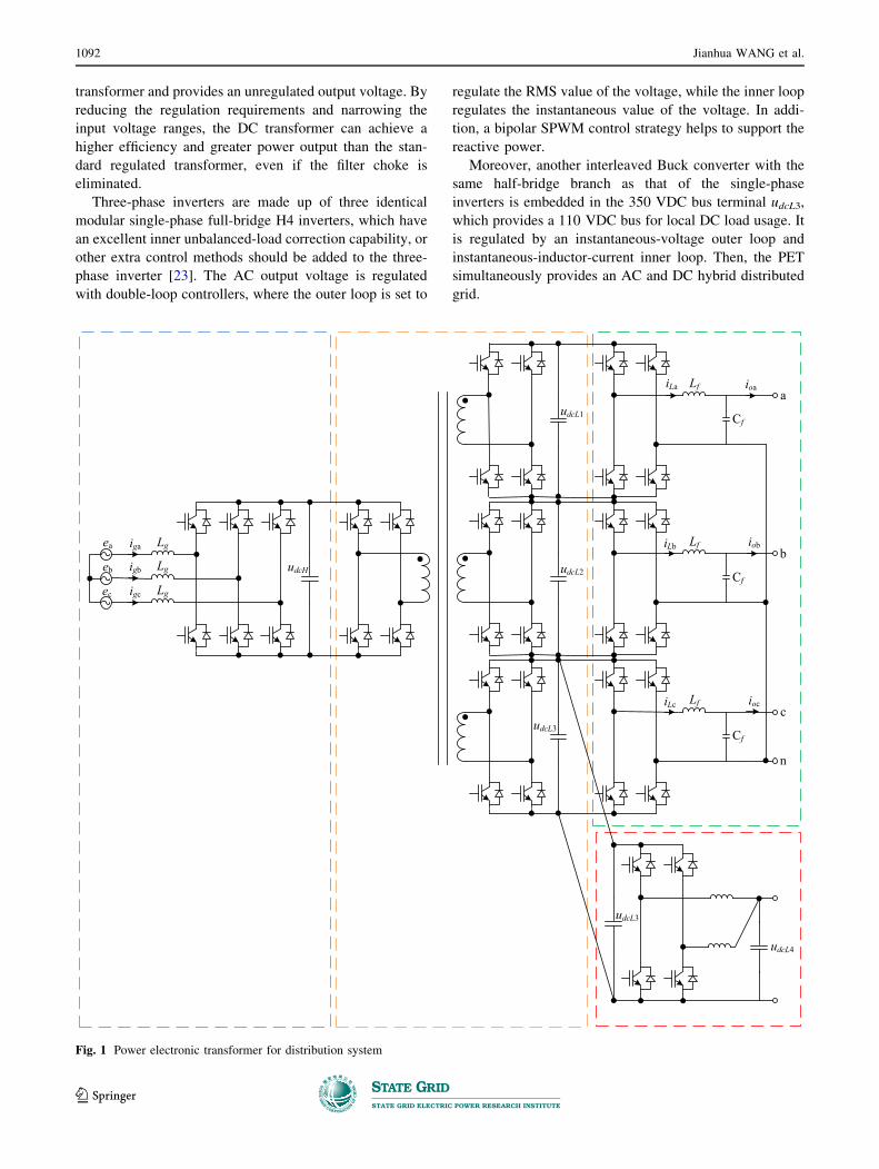
transformer and provides an unregulated output voltage. By
reducing the regulation requirements and narrowing the
input voltage ranges, the DC transformer can achieve a
higher efficiency and greater power output than the stan-
dard regulated transformer, even if the filter choke is
eliminated.
Three-phase inverters are made up of three identical
modular single-phase full-bridge H4 inverters, which have
an excellent inner unbalanced-load correction capability, or
other extra control methods should be added to the three-
phase inverter [23]. The AC output voltage is regulated
with double-loop controllers, where the outer loop is set to
regulate the RMS value of the voltage, while the inner loop
regulates the instantaneous value of the voltage. In addi-
tion, a bipolar SPWM control strategy helps to support the
reactive power.
Moreover, another interleaved Buck converter with the
same half-bridge branch as that of the single-phase
inverters is embedded in the 350 VDC bus terminal udcL3,
which provides a 110 VDC bus for local DC load usage. It
is regulated by an instantaneous-voltage outer loop and
instantaneous-inductor-current inner loop. Then, the PET
simultaneously provides an AC and DC hybrid distributed
grid.
ea
eb
ec
iga
igb
igc
Lg
Lg
Lg
Lf
Lf
Lf
Cf
Cf
Cf
a
b
iLa
iLb
iLc
ioa
iob
iocc
n
udcH
udcL1
udcL2
udcL3
udcL3
udcL4
Fig. 1 Power electronic transformer for distribution system
1092 Jianhua WANG et al.
123
The main parameters of the system are as follows:
1) Input stage: the rated line voltage is 600 VAC, the
rated line frequency is 50 Hz, the input inductance is
1.5 mH, the high-voltage DC link capacitors have a
capacitance of 2160 lF, a switching frequency of
4.8 kHz is selected considering the thermal issues for
the adopted device having a voltage rating of 1700 V,
and the semiconductor switches are SKM400GB176D
switches.
2) Isolation stage: the switching frequency is 2 kHz, the
primary–secondary ratio of the transformer is 3:1:1:1,
the low-voltage DC link capacitors have a capacitance
of 3000 lF, the primary semiconductor switches are
SKM400GB176D switches, and the secondary
switches are SKM300GB128D switches. A middle
frequency of 2 kHz is selected rather than a higher
frequency because the Gen-I PET project is developed
for the next-generation 10 kV PET in preparation for
high-voltage IGBT tests at 3300 V and 6500 V in the
near future.
3) Output stage: the output filter inductance is 0.4 mH,
the output filter capacitors have a capacitance of
50 lF, the switching frequency is 10 kHz, and all
switches are SKM300GB128D switches.
In Fig. 1, the proposed PET topology has an inner high-
voltage (udc = 1050 VDC) bus and a low-voltage
(udcL1,2,3 = 350 VDC) bus (a udc voltage command could
be set by operators, e.g., udc = 1200 VDC). Thus, voltage
and load-disturbance isolation would be possible with the
help of DC link buffer capacitors. Further efforts should
focus on the key control strategies, especially the front-end
rectifier.
3 Key strategies for PET for voltage-disturbanceride through
For a PET operated with a grid voltage disturbance,
observability and controllability are essential. The accurate
and fast detection of the frequency and phase angle of the
grid voltage is essential to ensure the correct generation of
reference signals and to cope with the utility codes, espe-
cially for those operated under common utility distortions
such as harmonics, voltage sags, frequency variations, and
phase jumps [21]. The dynamic change in the grid voltage
should be considered for fast control concerns. Therefore,
two key strategies for the PET have been investigated and
are separately presented in this section, including the
phase-locked loop (PLL) design methods, control princi-
ples, and small-signal model of the three-phase PWM
rectifier. The stability issues related to the grid-connected
three-phase PET are also discussed.
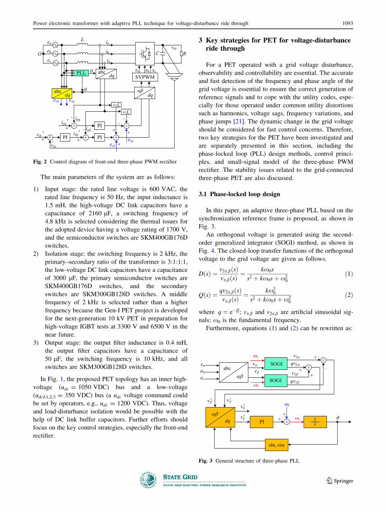
3.1 Phase-locked loop design
In this paper, an adaptive three-phase PLL based on the
synchronization reference frame is proposed, as shown in
Fig. 3.
An orthogonal voltage is generated using the second-
order generalized integrator (SOGI) method, as shown in
Fig. 4. The closed-loop transfer functions of the orthogonal
voltage to the grid voltage are given as follows:
DðsÞ ¼ v2a;bðsÞva;bðsÞ
¼ kx0s
s2 þ kx0sþ x20
ð1Þ
QðsÞ ¼ qv2a;bðsÞva;bðsÞ
¼ kx20
s2 þ kx0sþ x20
ð2Þ
where q ¼ e�jp2; va;b and v2a;b are artificial sinusoidal sig-
nals; x0 is the fundamental frequency.
Furthermore, equations (1) and (2) can be rewritten as:
Fig. 3 General structure of three-phase PLL
Fig. 2 Control diagram of front-end three-phase PWM rectifier
Power electronic transformer with adaptive PLL technique for voltage-disturbance ride through 1093
123
v2a;bðxÞ ¼ Dva;bðxÞ ð3Þ
qv2a;bðxÞ ¼ Qva;bðxÞ ð4Þ
where Dj j ¼ kxx0ffiffiffiffiffiffiffiffiffiffiffiffiffiffiffiffiffiffiffiffiffiffiffiffiffiffiffiffiffi
ðkxx0Þþðx2�x02Þ2
p ; \D ¼ tan�1ðx02�x2
kxx0Þ;
Qj j ¼ x0
x Dj j; \Q ¼ \D� p2:
Equation (4) indicates that no matter how x0, xand k change, va;b and v2a;b have a precise 90� phase
difference.
In addition, at x0, equations (3) and (4) are simplified as
follows:
v2a;bðx0Þ ¼ Dva;bðx0Þ ð5Þ
qv2a;bðx0Þ ¼ Qva;bðx0Þ ð6Þ
where Dj j ¼ 1; \D ¼ 0; Qj j ¼ 1; \Q ¼ � p2: This means
that the generated orthogonal system is filtered without any
delay at x0 owing to its resonance at x0.
In addition, the PLL output frequency is fed back to the
SOGI part, as shown in Figs. 3 and 4. Equations (1) and (2)
indicate that no matter how x0 changes, the bandwidth of
the filter is only determined by the given coefficient
k. Therefore, it is an adaptive PLL that is theoretically not
affected by the variation in the line frequency.
Figures 5, 6, 7 and 8 show the performance of the
adaptive SOGI-SPLL. Accurate and fast detection of the
frequency and phase angle of the grid voltage is achieved,
even if utility distortions such as harmonics, voltage sags,
and frequency variations occur.
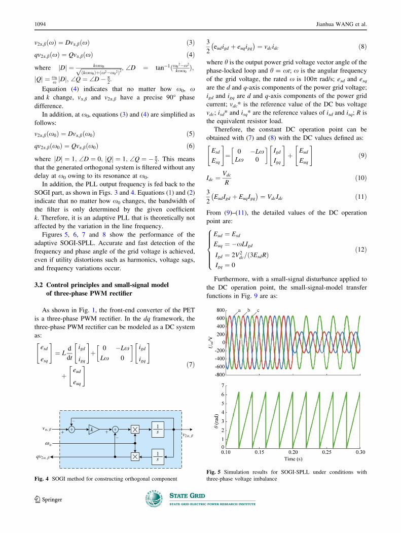
3.2 Control principles and small-signal model
of three-phase PWM rectifier
As shown in Fig. 1, the front-end converter of the PET
is a three-phase PWM rectifier. In the dq framework, the
three-phase PWM rectifier can be modeled as a DC system
as:
esd
esq
" #
¼ Ld
dt
igd
igq
" #
þ0 �Lx
Lx 0
� �
igd
igq
" #
þeud
euq
" # ð7Þ
3
2eudigd þ euqigq� �
¼ vdcidc ð8Þ
where h is the output power grid voltage vector angle of thephase-locked loop and h = xt; x is the angular frequency
of the grid voltage, the rated x is 100p rad/s; esd and esqare the d and q-axis components of the power grid voltage;
igd and igq are d and q-axis components of the power grid
current; vdc* is the reference value of the DC bus voltage
vdc; isd* and isq* are the reference values of isd and isq; R is
the equivalent resistor load.
Therefore, the constant DC operation point can be
obtained with (7) and (8) with the DC values defined as:
Esd
Esq
" #
¼ 0 �LxLx 0
� �
Igd
Igq
" #
þEud
Euq
" #
ð9Þ
Idc ¼Vdc
Rð10Þ
3
2EudIgd þ EuqIgq� �
¼ VdcIdc ð11Þ
From (9)–(11), the detailed values of the DC operation
point are:
Eud ¼ Esd
Euq ¼ �xLIgd
Igd ¼ 2V2dc=ð3EsdRÞ
Igq ¼ 0
8
>
>
>
>
<
>
>
>
>
:
ð12Þ
Furthermore, with a small-signal disturbance applied to
the DC operation point, the small-signal-model transfer
functions in Fig. 9 are as:
Fig. 4 SOGI method for constructing orthogonal component
Fig. 5 Simulation results for SOGI-SPLL under conditions with
three-phase voltage imbalance
1094 Jianhua WANG et al.
123

igdðsÞ ¼1
sLðesdðsÞ þ xLigqðsÞ � eudðsÞÞ ð13Þ
igqðsÞ ¼1
sLðesqðsÞ þ xLigdðsÞ � euqðsÞÞ ð14Þ
vdcðsÞ ¼ GpðsÞðIgdeudðsÞ þ EudigdðsÞ þ IqdeuqðsÞþ EuqigqðsÞÞ ð15Þ
GpðsÞ ¼3
2
1
sVdcCdc þ Idcð16Þ
eudðsÞ ¼ ðesdðsÞþxLigqðsÞ � ði�gdðsÞ � igdðsÞÞHc1ðsÞÞKn
ð17Þ
euqðsÞ ¼ ðesqðsÞ � xLigdðsÞ � ði�gqðsÞ � igqðsÞÞHc1ðsÞÞKn
ð18Þi�dðsÞ ¼ �vdcðsÞHv1ðsÞ ð19Þ
where Kn = Kpwm/(0.5Tss ? 1) for time delay control
concerns, Ts is the switching period, and Kpwm is the
equivalent gain of the main circuitry.
3.3 Stability issues of grid-connected three-phase
PET
The inclusion of a PET with a high number of power
electronics converters in an existing AC grid introduces a
number of technical issues that have not been previously
encountered. One concern is the potential instability caused
by PET interactions. This instability may take the form of a
harmonic resonance induced by the interaction between the
input impedance and the source output impedance, as
illustrated in Fig. 10, where the grid is emulated with an
ideal voltage source and its output impedance, whereas the
PET is modeled with the input impedance Zi or input
admittance Yi [24, 25].
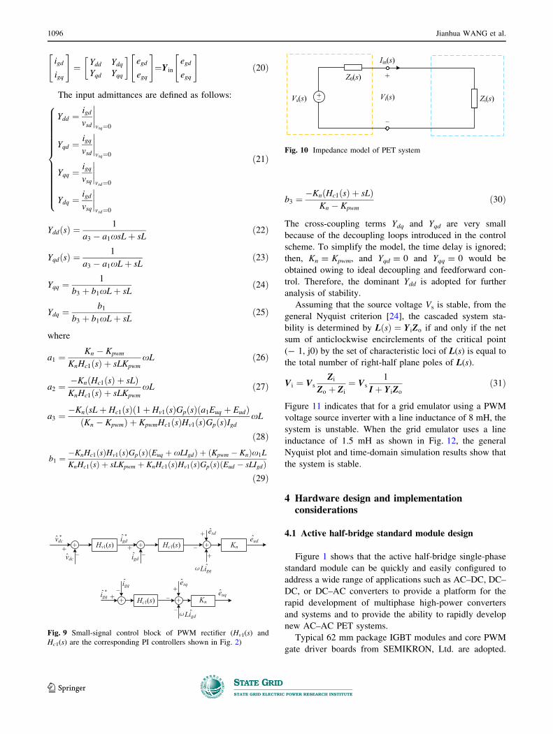
The input admittance matrix is expressed as:
Fig. 6 Simulation results for SOGI-SPLL under conditions with
input voltage drop
Fig. 7 Simulation results for SOGI-SPLL with harmonic voltage
input
Fig. 8 Simulation results for SOGI-SPLL with grid-frequency
fluctuations
Power electronic transformer with adaptive PLL technique for voltage-disturbance ride through 1095
123
igd
igq
" #
¼ Ydd YdqYqd Yqq
� �
egd
egq
" #
¼Yin
egd
egq
" #
ð20Þ
The input admittances are defined as follows:
Ydd ¼igd
vsd
�
�
�
�
vsq¼0
Yqd ¼igq
vsd
�
�
�
�
vsq¼0
Yqq ¼igq
vsq
�
�
�
�
vsd¼0
Ydq ¼igd
vsq
�
�
�
�
vsd¼0
8
>
>
>
>
>
>
>
>
>
>
>
>
>
<
>
>
>
>
>
>
>
>
>
>
>
>
>
:
ð21Þ
YddðsÞ ¼1
a3 � a1xsLþ sLð22Þ
YqdðsÞ ¼1
a3 � a1xLþ sLð23Þ
Yqq ¼1
b3 þ b1xLþ sLð24Þ
Ydq ¼b1
b3 þ b1xLþ sLð25Þ
where
a1 ¼Kn � Kpwm
KnHc1ðsÞ þ sLKpwm
xL ð26Þ
a2 ¼�KnðHc1ðsÞ þ sLÞKnHc1ðsÞ þ sLKpwm
xL ð27Þ
a3 ¼�KnðsLþ Hc1ðsÞð1þ Hv1ðsÞGpðsÞða1Euq þ EudÞ
ðKn � KpwmÞ þ KpwmHc1ðsÞHv1ðsÞGpðsÞIgdxL
ð28Þ
b1 ¼�KnHc1ðsÞHv1ðsÞGpðsÞðEuq þ xLIgdÞ þ ðKpwm � KnÞx1L
KnHc1ðsÞ þ sLKpwm þ KnHc1ðsÞHv1ðsÞGpðsÞðEud � sLIgdÞð29Þ
b3 ¼�KnðHc1ðsÞ þ sLÞ
Kn � Kpwm
ð30Þ
The cross-coupling terms Ydq and Yqd are very small
because of the decoupling loops introduced in the control
scheme. To simplify the model, the time delay is ignored;
then, Kn = Kpwm, and Yqd = 0 and Yqq = 0 would be
obtained owing to ideal decoupling and feedforward con-
trol. Therefore, the dominant Ydd is adopted for further
analysis of stability.
Assuming that the source voltage Vs is stable, from the
general Nyquist criterion [24], the cascaded system sta-
bility is determined by L sð Þ ¼ YiZo if and only if the net
sum of anticlockwise encirclements of the critical point
(- 1, j0) by the set of characteristic loci of L(s) is equal to
the total number of right-half plane poles of L(s).
Vi ¼ Vs
Zi
Zo þ Zi
¼ Vs
1
I þ YiZo
ð31Þ
Figure 11 indicates that for a grid emulator using a PWM
voltage source inverter with a line inductance of 8 mH, the
system is unstable. When the grid emulator uses a line
inductance of 1.5 mH as shown in Fig. 12, the general
Nyquist plot and time-domain simulation results show that
the system is stable.
4 Hardware design and implementationconsiderations
4.1 Active half-bridge standard module design
Figure 1 shows that the active half-bridge single-phase
standard module can be quickly and easily configured to
address a wide range of applications such as AC–DC, DC–
DC, or DC–AC converters to provide a platform for the
rapid development of multiphase high-power converters
and systems and to provide the ability to rapidly develop
new AC–AC PET systems.
Typical 62 mm package IGBT modules and core PWM
gate driver boards from SEMIKRON, Ltd. are adopted.
Fig. 9 Small-signal control block of PWM rectifier (Hv1(s) and
Hc1(s) are the corresponding PI controllers shown in Fig. 2)
Fig. 10 Impedance model of PET system
1096 Jianhua WANG et al.
123

Cycle-by-cycle protection functions are embedded in the
driver. Fiber-optic cables are used for reliable isolated
drive design. In addition, the auxiliary power interface,
control interface, and power interface are connected
through hardwired terminals, and some forced-air-cooling
heat sinks and laminated bus bars need slight modifications
due to mechanical and structural issues.
4.2 Digital control platform design
A power electronics universal control platform is
designed and implemented here, which covers AC–DC,
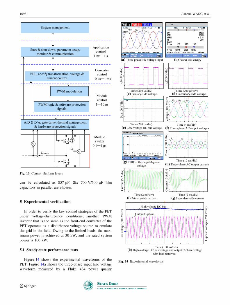
DC–DC, and DC–AC converters. Figure 13 shows that the
control platform provides a sufficient number of peripheral
interfaces to the commercially available digital signal
processor (DSP; TI 2808), including voltage, current, and
temperature sensors and A/D and D/A conversion of sensor
signal circuits.
4.3 Passive component design
DC power storage and a filter are needed in the input of
the isolation stage. Capacitors with a large capacitance are
usually used. The capacitors mainly have two functions.
One is to filter the DC voltage ripple caused by high-fre-
quency switching. The other is to maintain the DC voltage
fluctuation inside the qualified range within the inertial
delay time of the transformer when the loads change.
During the dynamic process, the amplitude of the volt-
age fluctuation caused by changes in the loads at the
moment t0 can be expressed as:
Dudc ¼1
C
Z 0þts
0
½i0ðtÞ � i1ðtÞ�dt ð32Þ
where ts is the settling time; i0(t) and i1(t) are the load and
output currents. ts is related to the response speed of the
voltage loop. The value of the DC capacitor can be
calculated according to the energy balance code. Suppose
that DPmax is the maximum variation in the load power,
Timax is the maximum inertial time of the rectifier, and
Dudcmax is the maximum voltage fluctuation. Then, the
maximum energy provided by a DC capacitor during the
dynamic process can be calculated as:
DW ¼ DPmaxTimax=2 ð33Þ
With (32) and (33), the capacitance of the DC capacitor can
be calculated as:
C�DPmaxTimax=ð2udcDudcmaxÞ ð34Þ
Setting DPmax ¼ 5 kW, Timax ¼ 1:2ms, Dudcmax ¼ 10V,
and udc = 1050 V, the minimum capacitance can be cal-
culated as 286 lF with (12). To reduce the hardware cost
and the equivalent series resistance of the capacitors, sev-
eral capacitors in parallel are adopted instead of one
capacitor with a large capacitance. Eight 1600 V/270 lFfilm capacitors in parallel are chosen in the DC stage of the
isolation part. Large capacitances are used for possible
heavy load usage.
In the output of the isolation part, the DC voltage of
each phase is 350 V. With (34), the minimum capacitance
0.1 0.2 0.3
0
1000500
-500
Vdc
ua-1000
0Tims (s)
ia
(a) Time-domain plot
1.5
1.0
0.5
0
-0.5-1.5 -1.0 -0.5 0 0.5 1.0
l1(s)q-ax
is
(b) Generalized Nyquist plot in dq domain
-1500
1500
0.4
Vol
tage
(V)
Cur
rent
(A)
l2(s)
d-axis
Fig. 11 Unstable system simulations (with a line inductance of
8 mH)
0.1 0.2 0.30
0
1000500
-500
Vdc
ua ia1000
(a) Time-domain plot
l1(s)
(b) Generalized Nyquist plot in dq domain
0.4Time (s)
1500
Vol
tage
(V)
Cur
rent
(A)
1.5
1.0
0.5
0
-0.5
q -ax
is
-1.0 -0.5 0 0.5 1.0
l2(s)
d-axis
Fig. 12 Stable system simulations (with a line inductance of 1.5 mH)
Power electronic transformer with adaptive PLL technique for voltage-disturbance ride through 1097
123
can be calculated as 857 lF. Six 700 V/500 lF film
capacitors in parallel are chosen.
5 Experimental verification
In order to verify the key control strategies of the PET
under voltage-disturbance conditions, another PWM
inverter that is the same as the front-end converter of the
PET operates as a disturbance-voltage source to emulate
the grid in the field. Owing to the limited loads, the max-
imum power is achieved at 30 kW, and the rated system
power is 100 kW.
5.1 Steady-state performance tests
Figure 14 shows the experimental waveforms of the
PET. Figure 14a shows the three-phase input line voltage
waveform measured by a Fluke 434 power quality
Power
u s(4
00 V
/div
)
Time (200 μs/div)
u p(2
00 V
/div
)
Time (200 μs/div)
Time (200 μs/div)U
dcl(1
00 V
/div
)Time (4 ms/div)
Vol
tage
(100
V/d
iv)
ua ub uc
uab ubc uca
(a) Three-phase line voltage input (b) Power and energy
(c) Primary-side voltage (d) Secondary-side voltage
(e) Low-voltage DC bus voltage (f) Three-phase AC output voltages
Cur
rent
(20
A/d
iv)
ia ib ic
(h) Three-phase AC output currents
Cur
rent
(5 A
/div
)
Cur
rent
(10
A/d
iv)
(i) Primary-side current (j) Secondary-side current
High voltage DC bus
Output C-phase
Time (10 ms/div)
Time (2 ms/div)Time (2 ms/div)
Time (100 ms/div)(k) High-voltage DC bus voltage and output C-phase voltage
with load removed
(g) THD of the output A-phasevoltage
Bus
vol
tage
(200
V/d
iv)
C-p
hase
vol
tage
(250
V/d
iv)
Fig. 14 Experimental waveforms
Lbranch
udc
A/D & D/A, gate drive, thermal management & hardware protection signals
PWM logic & software protection signals
PLL, abc/dq transformation, voltage & current control
PWM modulation
Start & shut down, parameter setup, monitor & communication
System management
Moduleswitch
0.1 1 μs
Modulecontrol
1 10 μs
Convertercontrol
10 μs 1 ms
Applicationcontrol
1 ms 1 s
V
TV
Fig. 13 Control platform layers
1098 Jianhua WANG et al.
123
analyzer, where uab is 597.1 V, ubc is 595.6 V, and uca is
593.5 V. Figure 14b shows the system operation parame-
ters. The load power is 14.83 kW, and the system power
factor is 0.95, which demonstrates that the input operates at
a high power factor. Figure 14c and 14(d) show the pri-
mary- and secondary-side voltages of the medium-fre-
quency isolated transformer. The single-phase full-bridge
rectifier converts the square AC wave into a 350 V direct
current. Figure 14e shows the extra DC output terminal of
the PET—a 110 VDC bus for the local DC load. Fig-
ure 14f shows the output three-phase AC voltage whose
waveforms are symmetrical and sinusoidal, and the RMS
voltage is 221 V. Compared with the reference 220 V, the
error is only 0.4%. Figure 14f shows the corresponding
three-phase load current. Figure 14g shows that the THD
of the output A-phase voltage is only 2.5%, which con-
forms to the national standard that the THD must be within
5%. The primary- and secondary-side currents of one
winding of the transformer are shown in Figs. 14i and 14j,
respectively. A double-output frequency variation of
100 Hz is observed in Fig. 14j because the unregulated DC
transformer topology is adopted [26]. When the C-phase
load is suddenly removed, an acceptable overshoot occurs
at the high-voltage DC bus, and the DC voltage is regulated
after 400 ms. In addition, the output C-phase voltage is
regulated well during the transition.
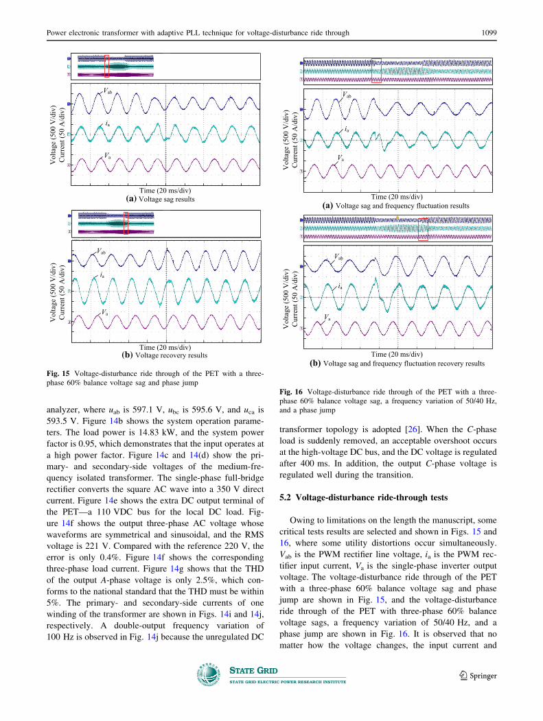
5.2 Voltage-disturbance ride-through tests
Owing to limitations on the length the manuscript, some
critical tests results are selected and shown in Figs. 15 and
16, where some utility distortions occur simultaneously.
Vab is the PWM rectifier line voltage, ia is the PWM rec-
tifier input current, Va is the single-phase inverter output
voltage. The voltage-disturbance ride through of the PET
with a three-phase 60% balance voltage sag and phase
jump are shown in Fig. 15, and the voltage-disturbance
ride through of the PET with three-phase 60% balance
voltage sags, a frequency variation of 50/40 Hz, and a
phase jump are shown in Fig. 16. It is observed that no
matter how the voltage changes, the input current and
Time (20 ms/div)
(b) Voltage recovery resultsTime (20 ms/div)
Vol
tage
(500
V/d
iv)
Cur
rent
(50
A/d
iv)
Vol
tage
(500
V/d
iv)
Cur
rent
(50
A/d
iv)
(a) Voltage sag results
Vab
ia
Va
Vab
ia
Va
Fig. 15 Voltage-disturbance ride through of the PET with a three-
phase 60% balance voltage sag and phase jump
(a) Voltage sag and frequency fluctuation resultsTime (20 ms/div)
Vol
tage
(500
V/d
iv)
Cur
rent
(50
A/d
iv)
Vol
tage
(500
V/d
iv)
Cur
rent
(50
A/d
iv)
(b) Voltage sag and frequency fluctuation recovery resultsTime (20 ms/div)
Vab
ia
Va
Vab
ia
Va
Fig. 16 Voltage-disturbance ride through of the PET with a three-
phase 60% balance voltage sag, a frequency variation of 50/40 Hz,
and a phase jump
Power electronic transformer with adaptive PLL technique for voltage-disturbance ride through 1099
123
output voltage are both well-regulated with a fast dynamic
response. The input power quality is only affected for two
or three grid periods. The output voltage changes are not
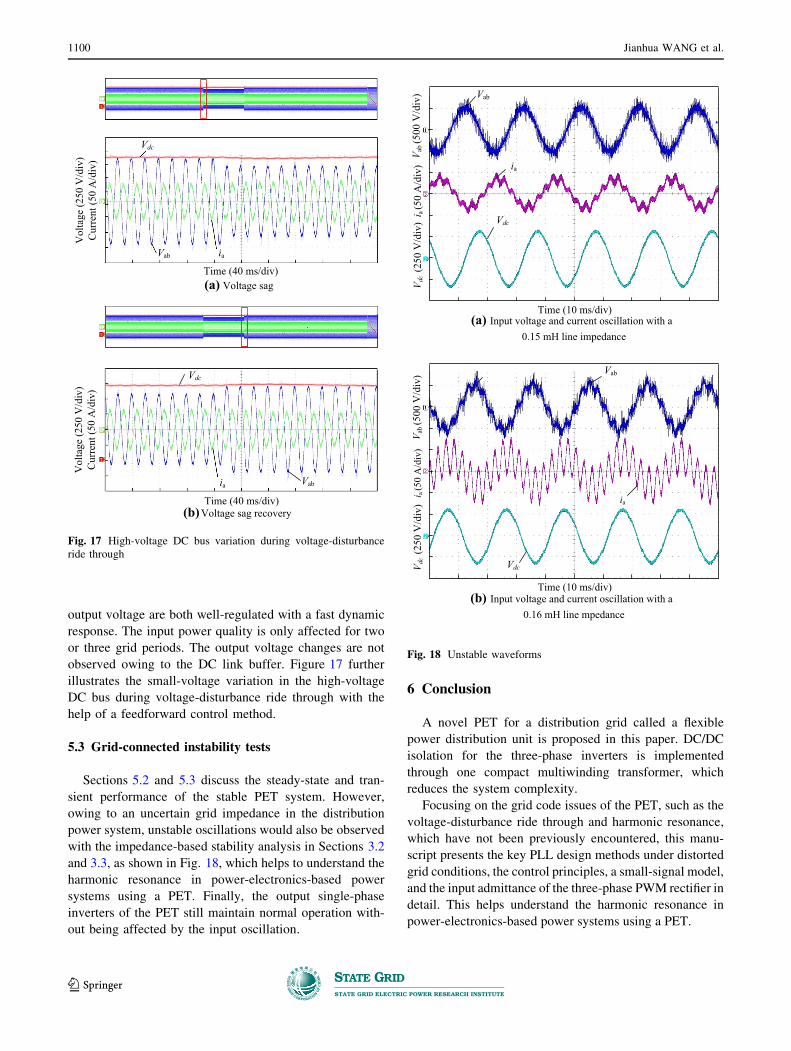
observed owing to the DC link buffer. Figure 17 further
illustrates the small-voltage variation in the high-voltage
DC bus during voltage-disturbance ride through with the
help of a feedforward control method.
5.3 Grid-connected instability tests
Sections 5.2 and 5.3 discuss the steady-state and tran-
sient performance of the stable PET system. However,
owing to an uncertain grid impedance in the distribution
power system, unstable oscillations would also be observed
with the impedance-based stability analysis in Sections 3.2
and 3.3, as shown in Fig. 18, which helps to understand the
harmonic resonance in power-electronics-based power
systems using a PET. Finally, the output single-phase
inverters of the PET still maintain normal operation with-
out being affected by the input oscillation.
6 Conclusion
A novel PET for a distribution grid called a flexible
power distribution unit is proposed in this paper. DC/DC
isolation for the three-phase inverters is implemented
through one compact multiwinding transformer, which
reduces the system complexity.
Focusing on the grid code issues of the PET, such as the
voltage-disturbance ride through and harmonic resonance,
which have not been previously encountered, this manu-
script presents the key PLL design methods under distorted
grid conditions, the control principles, a small-signal model,
and the input admittance of the three-phase PWM rectifier in
detail. This helps understand the harmonic resonance in
power-electronics-based power systems using a PET.
(a) Voltage sag Time (40 ms/div)
ia
ia
Vol
tage
(250
V/d
iv)
Cur
rent
(50
A/d
iv)
Vol
tage
(250
V/d
iv)
Cur
rent
(50
A/d
iv)
Vdc
Vab
Vdc
Vab
(b) Voltage sag recoveryTime (40 ms/div)
Fig. 17 High-voltage DC bus variation during voltage-disturbance
ride through
Vdc
ia
Time (10 ms/div)(a) Input voltage and current oscillation with a
0.15 mH line impedance
Vdc
ia
(b) Input voltage and current oscillation with a 0.16 mH line mpedance
Time (10 ms/div)
Vab
Vab
V ab (5
00 V
/div
)i a
(50
A/d
iv)
V dc
(250
V/d
iv)
V ab (5
00 V
/div
)i a
(50
A/d
iv)
V dc
(250
V/d
iv)
Fig. 18 Unstable waveforms
1100 Jianhua WANG et al.
123
Although the cost, volume, and weight of the PET are
presently much higher than those of conventional power
transformers, the future of the PET is still promising, as it
can play many different but important roles in future smart
grid and Energy Internet applications.
Acknowledgements This work was supported in part by the National
Basic Research Program of China (No. 2016YFB0900404), the
National Natural Science Foundation of China (No. 51477030, No.
51207023), the Cooperative Innovation Fund of Jiangsu Province–the
Prospective and Joint Research Project (No. BY2015070-18), the
Basic and Prospective Science and Technology Project of State Grid
Corporation of China (No. PD71-17-024), and the Fundamental
Research Funds for the Central Universities (No. 2242017K40159).
Open Access This article is distributed under the terms of the
Creative Commons Attribution 4.0 International License (http://
creativecommons.org/licenses/by/4.0/), which permits unrestricted
use, distribution, and reproduction in any medium, provided you give
appropriate credit to the original author(s) and the source, provide a
link to the Creative Commons license, and indicate if changes were
made.
References
[1] McMurray W (1971) The thyristor electronic transformer: a
power converter using a high-frequency link. IEEE Trans Ind
Gen Appl 7(4):451–457
[2] MIT (2011) Emerging technologies breakthroughs that are
bursting into our lives. Technol Rev 44–45
[3] Lai JS, Maitra A, Mansoor A et al (2005) Multilevel intelligent
universal transformer for medium voltage applications. In:
Proceeding of the IEEE IAS, Kowloon, Hong Kong, 2–6 Oct
2005, 7 pp
[4] Huang A, Crow ML, Heydt GT et al (2011) The future
renewable electric energy delivery and management (FREEDM)
system: the energy internet. Proc IEEE 99(1):133–148
[5] Quartarone G, Liserre M, Fuchs F et al (2014) Impact of the
modularity on the efficiency of smart transformer solutions. In:
Proceeding of the IEEE IECON, Dallas, USA, 29 Oct–1 Nov, 7
pp
[6] Claessens M, Dujic D, Canales F et al (2012) Traction trans-
formation—a power-electronic traction transformer (PETT).
ABB Rev 1(12):11–17
[7] Iov F, Blabjerg F, Clare J et al (2009) UNIFLEX-PM-A key-
enabling technology for future European electricity networks.
EPE J 19(4):6–16
[8] Zhao J (2003) Simulation study of a power electronic trans-
former with constant output voltage. Autom Electr Power Syst
27(18):30–34
[9] Briz F, Lopez M, Rodriguez A et al (2016) Modular power
electronic transformers: modular multilevel converter versus
cascaded H-bridgesolutions. IEEE Ind Electron Mag 10(4):1–19
[10] Wang D, Tian J, Mao C et al (2016) A 10-kv/400-v 500-kva
electronic power transformer. IEEE Trans Ind Electron
63(11):6653–6663
[11] She X, Yu X, Wang F et al (2014) Design and demonstration of
a 3.6-kV–120-V/10-kVA solid-state transformer for smart grid
application. IEEE Trans Power Electron 29(8):3982–3996
[12] Drofenik U (2012) A 150 kW medium frequency transformer
optimized for maximum power density. In: Proceeding of the
IEEE CIPS, Nuremberg, Germany, 6–8 March 2012, 6 pp
[13] Siemaszko D, Zurkinden F, Fleischli L et al (2009) Description
and efficiency comparison of two 25 kVA DC/AC isolation
modules. EPE J 19(4):17–24
[14] Zhao B, Song Q, Liu W (2015) A practical solution of high-
frequency-link bidirectional solid state transformer based on
advanced components in hybrid micro-grid. IEEE Trans Ind
Electron 62(7):4587–4597
[15] Huber J, Kolar JW (2015) Analysis and design of fixed voltage
transfer ratio DC/DC converter cells for phase-modular solid-
state transformers. In: Proceedings of the IEEE ECCE USA,
Montreal, Canada, 20–24 Sept 2015, 9 pp
[16] Wang X, Liu J, Ouyang S et al (2015) Research on unbalanced-
load correction capability of two power electronic transformer
topologies. IEEE Trans Power Electron 30(6):3044–3056
[17] Kolar JW, Huber J, Guillod T et al (2015) Research challenges
and future perspectives of solid-state transformers. In: Pro-
ceedings of the 5th international conference on power engi-
neering, energy and electrical drives (POWERENG 2015), Riga,
Latvia, 11–13 May 2015
[18] Hooshmand R, Ataei M, Rezaei M (2012) Improving the
dynamic performance of distribution electronic power trans-
formers using sliding mode control. J Power Electron
12(1):145–156
[19] Acikgoz H, Kececioglu O, Yildiz C et al (2016) Performance
analysis of electronic power transformer based on neuro-fuzzy
controller. SpringerPlus 5:1350
[20] Li Y, Han J, Cao Y et al (2017) A modular multilevel converter
type solid state transformer with internal model control method.
Int J Electr Power Energy Syst 85:153–163
[21] Teodorescu R, Liserre M, Rodriguez P (2011) Grid converters
for photovoltaic and wind power systems. Wiley, New York
[22] Shah DG, Crow ML (2014) Stability design criteria for distri-
bution systems with solid-state transformers. IEEE Trans Power
Deliv 29(6):2588–2595
[23] Shi H, Zhuo F, Hao Yi et al (2016) Control strategy for
microgrid under three-phase unbalance condition. J Mod Power
Syst Clean Energy 4(1):94–102
[24] Sudhoff SD, Glover SF, Lamm PT et al (2000) Admittance
space stability analysis of power electronic systems. IEEE Trans
Aerosp Electron Syst 36(3):965–973
[25] Chen Z, Chen Y, Guerrero JM et al (2016) Generalized coupling
resonance modeling, analysis, and active damping of multi-
parallel inverters in microgrid operating in grid-connected
mode. J Mod Power Syst Clean Energy 4(1):63–75
[26] Wang J, Ji B, Lu X et al (2014) Steady-state and dynamic input
current low frequency ripple evaluation and reduction in two-
stage single phase inverters with back current gain model. Trans
Power Electron 29(8):4247–4260
Jianhua WANG received the B.S. and Ph.D. degrees in electrical
engineering from Nanjing University of Aeronautics & Astronautics,
Nanjing, China, in 2004 and 2010, respectively. In 2010, he joined the
faculty of School of Electrical Engineering in Southeast University,
Nanjing, China, where he is currently an Associate Research
Professor. He has published more than 30 technical papers. He is
the holder of 2 China patents. His main research interests are solid-
state power electronic transformer, power electronics system stability,
general power electronic circuit topologies, modeling, and control.
Power electronic transformer with adaptive PLL technique for voltage-disturbance ride through 1101
123
Fangfang LUO received the B.S degree the School of Automation in
Nanjing University of Science and Technology, Nanjing, China, in
2010. Now she is studying for her M.S. degree in School of Electrical
Engineering in Southeast University, Nanjing, China. Her main
research interests are solid-state power electronic transformer, power
electronics system stability, modeling and control of new energy
system.
Qing DUAN received the Ph.D. degree of Power System and
Automation from Shandong University, China in 2010, and then had a
post-doctor research experience in China Electric Power Research
Institute (CEPRI) in 2011–2013. He currently is a senior engineer and
IEEE member in Power Distribution Department of CEPRI, Beijing
Key Laboratory of Distribution Transformer Energy-saving Technol-
ogy. He is engaged in the research of intelligent power distribution
system, planning, operation and control, power electronics technolo-
gies, artificial intelligence and DGs access technologies. He has been
successively responsible for more than 10 science and technology
projects. What’s more, he has published more than 30 significant
papers in core journals, academic meeting, he also had several
scientific patents and won some progress prize of scientific and
collective technologies.
Zhendong JI received the B.S. and Ph.D. degrees in electrical
engineering from Southeast University, Nanjing, China, in 2007 and
2015, respectively. Since 2015, he joined the School of Automation in
Nanjing University of Science and Technology, Nanjing, China,
where he is currently a lecturer. His main research interests include
cascade multilevel converters and solid-state transformers.
Binshi GU received the B.S. degree in electrical engineering from
Nanjing Tech University, and M.S. degree in School of Electrical
Engineering from Southeast University, Nanjing, China, in 2010,
2017 respectively. Now he is with State Grid Nantong Power Supply
Company, Nantong, China. His main research interests are solid-state
power electronic transformer, power electronics system stability and
virtual synchronous generator.
Jun YOU received his B.S. degree in Automation from Nanjing
University of Aeronautics and Astronautics, Nanjing, China, in 1998.
He received his M.S. degree in Power Electronics and Electrical
Drive and Ph.D. degree in Electrical Engineering from Southeast
University, Nanjing, China, in 2001 and 2012, respectively. Since
2001, he has been with the School of Electrical Engineering,
Southeast University, where he is currently an Associate Professor.
Since 2010, he has also been the Deputy Director of Suzhou Key
Laboratory of Electrical Equipment and Automation of Research
Institute of Southeast University in Suzhou, China. His main research
interests include power electronics, grid connected renewable energy
systems and power quality monitoring.
Wei GU received his B.Eng. degree and Ph.D. degree in Electrical
Engineering from Southeast University, China, in 2001 and 2006.
From 2009 to 2010, he was a Visiting Scholar in the Department of
Electrical Engineering, Arizona State University, Tempe, AZ 85287,
USA. He is now a professor in the School of Electrical Engineering,
Southeast University. His research interests are power system stability
and control, smart grid, renewable energy technology and power
quality.
Jianfeng ZHAO received the B.S. from Huainan Mining Institute,
Huainan, China, and the M.S. degree from Nanjing University of
Aeronautics & Astronautics, Nanjing, China, and Ph.D. degrees from
Southeast University, Nanjing, China, in 1995, 1998, and 2001,
respectively, all in electrical engineering. In 2001, he joined the
faculty of School of Electrical Engineering in Southeast University,
and he became a Professor since 2008, where he has been engaged in
teaching and research in the field of high power electronics. Since
2014, he has also been the Dean of School of Electrical Engineering,
Southeast University. He has published more than 100 technical
papers. His main research interests are utility applications of power
electronics in smart grid such as solid state transformer, active filters
for power conditioning, FACTs devices, multilevel AC motor drives,
and efficient energy utilization.
1102 Jianhua WANG et al.
123