printed when - nie networks
TRANSCRIPT
SPECIFICATION
200-011
36 kV Outdoor
Voltage Transformers
28th February 2018
UNCONTROLLED W
HEN PRIN
TED
200-011 Issue 4 – February 2018
Page ii
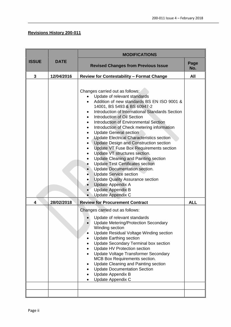
Revisions History 200-011
ISSUE
DATE
MODIFICATIONS
Revised Changes from Previous Issue Page No.
3 12/04/2016 Review for Contestability – Format Change All
Changes carried out as follows:
Update of relevant standards
Addition of new standards BS EN ISO 9001 & 14001, BS 5493 & BS 60947-2
Introduction of International Standards Section
Introduction of Oil Section
Introduction of Environmental Section
Introduction of Check metering information
Update General section
Update Electrical Characteristics section
Update Design and Construction section
Update VT Fuse Box Requirements section
Update VT structures section.
Update Cleaning and Painting section
Update Test Certificates section
Update Documentation section.
Update Service section
Update Quality Assurance section
Update Appendix A
Update Appendix B
Update Appendix C
4 28/02/2018 Review for Procurement Contract ALL
Changes carried out as follows:
Update of relevant standards
Update Metering/Protection Secondary Winding section
Update Residual Voltage Winding section
Update Earthing section
Update Secondary Terminal box section
Update HV Protection section
Update Voltage Transformer Secondary MCB Box Requirements section.
Update Cleaning and Painting section
Update Documentation Section
Update Appendix B
Update Appendix C
UNCONTROLLED W
HEN PRIN
TED

200-011 Issue 4 – February 2018
Page iii
Specification 200-11
36kV Outdoor voltage transformers Table of Contents
1 General .......................................................................................................................... 1
1.1 Scope ..................................................................................................................... 1
1.2 Standards ............................................................................................................... 1
1.2.1 European Standards ........................................................................................ 1
1.2.2 International Standards .................................................................................... 1
1.2.3 National Standards .......................................................................................... 2
1.2.4 ENA Technical Specifications .......................................................................... 2
1.2.5 NIE Networks Specifications ............................................................................ 2
1.3 Service Conditions .................................................................................................. 2
1.4 System Conditions .................................................................................................. 2
2 Electrical Characteristics ................................................................................................ 3
2.1 Type ....................................................................................................................... 3
2.2 Rated of Voltage Transformers ............................................................................... 3
2.3 Primary Voltage Ratio ............................................................................................. 3
2.4 Metering/Protection Secondary Winding ................................................................. 3
2.5 Residual Voltage Winding ....................................................................................... 3
2.6 Accuracy Class of Windings .................................................................................... 3
2.7 VA Rating of Windings ............................................................................................ 4
2.8 Mounting Details ..................................................................................................... 4
2.9 Secondary Terminal Box ......................................................................................... 4
3 Design and Construction ................................................................................................ 4
3.1 Transformer Tanks .................................................................................................. 4
3.1.1 General ............................................................................................................ 4
3.2 Rigid Tanks ............................................................................................................. 5
3.3 Non-Rigid Tanks ..................................................................................................... 5
3.4 Oil ........................................................................................................................... 5
3.4.1 General ............................................................................................................ 5
3.4.2 PCB ................................................................................................................. 5
3.5 HV Bushings ........................................................................................................... 5
3.5.1 General ............................................................................................................ 5
3.5.2 Performance .................................................................................................... 5
3.5.1 HV Lightning Protection ................................................................................... 5
3.5.2 Identification .................................................................................................... 5
UNCONTROLLED W
HEN PRIN
TED

200-011 Issue 4 – February 2018
Page iv
3.6 HV Fusing ............................................................................................................... 6
3.7 Earthing .................................................................................................................. 6
4 Voltage Transformer Fuse Box Requirements ............................................................... 6
4.1 General ................................................................................................................... 6
4.2 Construction............................................................................................................ 6
4.3 Equipping of Fuse Box ............................................................................................ 6
5 Voltage Transformer Structures ..................................................................................... 7
5.1 General ................................................................................................................... 7
6 Cleaning and Painting .................................................................................................... 7
6.1 General ................................................................................................................... 7
6.2 Surface Preparation ................................................................................................ 7
6.3 Coating Systems ..................................................................................................... 7
6.4 Paint Finish ............................................................................................................. 7
6.5 Other Requirements ................................................................................................ 8
7 Testing ........................................................................................................................... 8
7.1 General ................................................................................................................... 8
8 Documentation ............................................................................................................... 8
8.1 Maintenance Instructions ........................................................................................ 8
8.2 Drawings and Information ....................................................................................... 8
9 Service ........................................................................................................................... 9
9.1 Spare Parts ............................................................................................................. 9
9.2 Delivery ................................................................................................................... 9
10 Quality Assurance ...................................................................................................... 9
10.1 Quality System and Inspection ................................................................................ 9
10.2 Environment.......................................................................................................... 10
11 Schedule of Requirements ....................................................................................... 11
12 APPENDIX A ............................................................................................................ 11 UNCONTROLLED W
HEN PRIN
TED

200-011 Issue 4 – February 2018
1
1 General
1.1 Scope
This specification covers the supply and delivery to sites within the Northern Ireland Electricity Networks area of supply, of 36 kV outdoor voltage transformers complete with separately mounted fuse boxes and supporting steelwork.
The life expectancy of the transformers shall be not less than 40 years and the choice of components and accessories shall not limit the life expectancy.
1.2 Standards
The voltage transformers shall in general comply with the references and related documents below. Where any provision of this NIE Networks specification differs from those listed, the provision of this specification shall apply.
1.2.1 European Standards
To be read in conjunction with the latest version
BS EN 14713-1 Guidelines and recommendations for the protection against corrosion of iron and steel in structures.
BS EN 60076-1 Power Transformers. General.
BS EN 60137 Insulated bushings for alternating voltages above 1kV.
BS EN 60270 High voltage test techniques. Partial discharge measurements.
BS EN 60296 Fluids for electro – technical applications. Unused mineral insulating oils for transformers and switchgear.
BS EN 60507 Artificial pollution tests on high-voltage ceramic and glass insulators to be used on a.c. system
BS EN 60529 & A2 Specification for degrees of protection provided by enclosures.
BS EN 60815-2 Selection and dimensioning of high-voltage insulators intended for use in polluted conditions. Ceramic and glass insulators for a.c. systems
BS EN 61869-3 Instrument transformers – Additional requirements for inductive voltage transformers.
BS EN 60947-2 Low voltage switchgear and control gear. Circuit Breakers BS EN 62271-1 & A1 Common specifications for high-voltage switchgear and controlgear standards.
BS EN ISO 9001 Quality management systems.
BS EN ISO 14001 Environmental management systems
1.2.2 International Standards
IEC 60997: Determination of poly chlorinated biphenyls (PCBs) in mineral insulating oils by packed column gas chromatography.
UNCONTROLLED W
HEN PRIN
TED

200-011 Issue 4 – February 2018
2
1.2.3 National Standards
BS CP 3 Chapter 5, Part 2: Wind Loads
BS 381C Specification for colours for identification, coding and special purposes.
BS 923-1 Guide on high-voltage testing techniques (Associated Standard: BS EN 60269).
BS 5493 Code of Practice for protective coating of iron and steel structures against corrosion
BS 7354 Code of Practice for design of high-voltage open-terminal stations.
BS HD 60269-2013 Low voltage fuses. Supplementary requirements for fuses for use by Authorised Persons (fuses mainly for industrial application). Examples of standardized systems of fuses A to J
1.2.4 ENA Technical Specifications
ENA Technical Specifications 35-1 Distribution transformers (from 16kVA to 2000kVA)
ENA Technical Specification 50-18 Design and application of ancillary electrical equipment.
ENA Technical Specification 98-1 Environmental classification and corrosion protection of structures, plant and equipment.
1.2.5 NIE Networks Specifications
211-03 Design and application of ancillary Electrical Equipment
1.3 Service Conditions
The transformers will be located outdoors in an electrically exposed location less than 1,000 metres above sea level, in a salty atmosphere with high humidity.
The following ambient temperature conditions detailed in Table 1 shall apply:
Environmental conditions Value
Minimum temperature -25C
Annual average temperature +20C
Maximum temperature +40C
Maximum daily average temperature +30C
Table 1: Environmental conditions
Wind Loading: In accordance with BS CP3, Chapter 5
Ice Loading: Max radial ice thickness of 12.5mm
1.4 System Conditions
The voltage transformers are for use on the NIE Network’s 33,000 volt (33kV), 3-phase, 50 Hz network with standard phase rotation. 33kV system details are as below: - (a) System Voltage: 33kV
UNCONTROLLED W
HEN PRIN
TED

200-011 Issue 4 – February 2018
3
(b) Highest System Voltage: 36kV (c) No. of Phases: 3 (d) System Frequency: 50 Hz (e) Method of Neutral Earthing: Earthing Transformer Electrical Characteristics
1.5 Type
Voltage transformers shall be suitable for metering and protection proposes in accordance with BS EN 61869-3. They shall be oil immersed or dry type, and be of 3- phase five limb construction.
1.6 Rated of Voltage Transformers
Rated voltage of the voltage transformer shall be 33 kV
Rated insulation levels of the voltage transformer shall be in accordance with BS EN 60076
(a) Lightning impulse withstand to earth, between poles - 170kV.
(b) Power frequency 1 minute wet and dry with-stand voltage - 95kV.
Voltage factor shall be 1.2 continuous, and 1.9 for 30 seconds
1.7 Primary Voltage Ratio
The primary winding shall be star connected and wound for 33/√3 kV per limb. The neutral point shall be brought out to a 1000 volt bushing to be connected to earth by NIE Networks.
1.8 Metering/Protection Secondary Winding
The secondary winding shall be star connected and wound for 63.5 V per limb. The neutral shall be earthed in a separately mounted VT secondary fuse box as detailed in Appendix C. The winding shall be star connected at the winding internal to the voltage transformer, ie 4 wires to be brought down into the secondary terminal box.
The metering/protection winding is to have the secondary neutral terminal earthed, see appendix C.
1.9 Residual Voltage Winding
Where specified in Schedule 1, a residual voltage winding shall be provided connected in broken delta. This shall be wound for 63.5 V per limb. Both ends of each phase winding shall be brought out through the secondary terminal box into the secondary VT MCB box, where it shall be possible to make the open delta connection. The open delta connection shall be made in the separate secondary VT MCB terminal box as detailed in Appendix C. A method of providing ferroresonance damping for the residual voltage winding shall be provided. This shall be by a suitably rated resistor connected across the da-dn terminals in the VT secondary MCB box as determined and supplied by the manufacturer.
1.10 Accuracy Class of Windings
The accuracy class of voltage transformer winding shall be as follows: -
(1) Secondary Winding: - (a) Metering class 0.5
(2) Secondary Winding:- (a) Metering and Protection class 0.5/6P
UNCONTROLLED W
HEN PRIN
TED
200-011 Issue 4 – February 2018
4
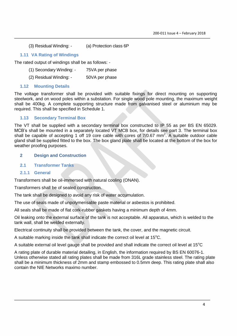
(3) Residual Winding: - (a) Protection class 6P
1.11 VA Rating of Windings
The rated output of windings shall be as follows: -
(1) Secondary Winding: - 75VA per phase
(2) Residual Winding: - 50VA per phase
1.12 Mounting Details
The voltage transformer shall be provided with suitable fixings for direct mounting on supporting steelwork, and on wood poles within a substation. For single wood pole mounting, the maximum weight shall be 400kg. A complete supporting structure made from galvanised steel or aluminium may be required. This shall be specified in Schedule 1.
1.13 Secondary Terminal Box
The VT shall be supplied with a secondary terminal box constructed to IP 55 as per BS EN 65029. MCB’s shall be mounted in a separately located VT MCB box, for details see part 3. The terminal box shall be capable of accepting 1 off 19 core cable with cores of 7/0.67 mm2. A suitable outdoor cable gland shall be supplied fitted to the box. The box gland plate shall be located at the bottom of the box for weather proofing purposes.
2 Design and Construction
2.1 Transformer Tanks
2.1.1 General
Transformers shall be oil-immersed with natural cooling (ONAN).
Transformers shall be of sealed construction.
The tank shall be designed to avoid any risk of water accumulation.
The use of seals made of unpolymerisable paste material or asbestos is prohibited.
All seals shall be made of flat cork-rubber gaskets having a minimum depth of 4mm.
Oil leaking onto the external surface of the tank is not acceptable. All apparatus, which is welded to the tank wall, shall be welded externally.
Electrical continuity shall be provided between the tank, the cover, and the magnetic circuit.
A suitable marking inside the tank shall indicate the correct oil level at 15oC.
A suitable external oil level gauge shall be provided and shall indicate the correct oil level at 15oC
A rating plate of durable material detailing, in English, the information required by BS EN 60076-1. Unless otherwise stated all rating plates shall be made from 316L grade stainless steel. The rating plate shall be a minimum thickness of 2mm and stamp embossed to 0.5mm deep. This rating plate shall also contain the NIE Networks maximo number.
UNCONTROLLED W
HEN PRIN
TED

200-011 Issue 4 – February 2018
5
2.2 Rigid Tanks
Rigid tanks shall comply with the oil preservation and enclosure integrity requirements of ENATS 35 – 1 section 8.2: “Sealed – tank system with gas cushion, in which a volume of gas above the oil surface in a stiff tank accommodates the oil expansion under variable pressure”.
2.3 Non-Rigid Tanks
Non-rigid tanks will be considered provided the design offered is such that no permanent deformation of the tank occurs over the full range of transformer loading, up to a maximum overload at maximum ambient temperature and that the tank will withstand an unlimited number of load cycles.
2.4 Oil
2.4.1 General
The insulating oil shall be Class 1 mineral oil to BS EN 60296. The complete first filling shall be new oil provided by the Supplier. If an anti-oxidant is recommended, its use shall be subject to NIE Networks approval.
2.4.2 PCB
The oil shall not include polychlorinated biphenyls (PCB), polychloroterphenyls (PCT) or polychlorobenzyltoluene (PCBT). The material used for the transformers such as insulating materials, varnishes, paints etc., shall also not contain PCB, PCT or PCBT. The concentration of PCB shall be less than the limit detection measurement of the measurement method specified in IEC 60997.
2.5 HV Bushings
2.5.1 General
HV bushings shall be either polymeric or composite outdoor immersed type, in accordance with BS EN 60137 and easily replaceable; cemented-in types are not acceptable. The preferred bushing colour, is light grey number 70, Munsell Notation SBG70.0/0.4, or similar.
Three phase transformers (NIE Networks Type 2) shall have three fully rated high voltage bushings.
2.5.2 Performance
HV bushings shall, in general, comply with the requirements of BS EN 60137 and BS EN 60507. HV bushings shall be suitable for a coastal environment. The minimum nominal creepage distance for the ALS (Alternative Long Short) insulator between phase and earth shall be in accordance with IEC 60815-3 Figure 1 for the case of heavy pollution levels – Class d. (Based on Unified Specific Creepage Distance of 43.3mm/kV, system highest voltage of 36 kV and the appropriate shed diameter factor, kD.)
2.5.1 HV Lightning Protection
Bushings shall be puncture proof and shall flashover externally before puncture or insulation failure. This shall be achieved by the application of double gap crossed cylinder arcing horns.
For 33kV arc gaps to be 2 x 90mm.
2.5.2 Identification
The transformer bushings shall be identified by engraving or cold stamping on the tank. (L1, L2 & L3 – capital L, for HV bushings).
UNCONTROLLED W
HEN PRIN
TED

200-011 Issue 4 – February 2018
6
2.6 HV Protection
The preferred option is for primary internal VT protection. Internal MCB’s shall be easily accessible. I.e. Access cover clearly labelled and no oil should be required to be removed.
2.7 Earthing
The voltage transformer shall be fitted with an earthing terminal, for connection to earth via a copper 70mm2 cable lug connection. A fixed metal label shall be fitted to donate the earth connection point.
3 Voltage Transformer Secondary MCB Box Requirements
3.1 General
A separately mounted MCB box shall be provided as per Schedule 1 and Appendix C.
3.2 Construction
The MCB box shall be of from stainless steel grade 340L over painted metal constructed to IP55, as per BS EN 65029. It shall be suitable for mounting on a steel structure or wood pole, and shall be fitted with a means of padlocking. The bottom of the box shall be suitable for glanding 3 off 7-core cable with 7/0.67 mm2 cores and 1 off 19-core cable with 7/0.67 mm2 cores. Suitable cable glands shall be provided fitted to the gland plate.
Locking facilities shall be suitable for padlocks having a shackle of 7 mm diameter. The hole for the shackle shall be not less than 8 mm diameter. Padlocks are not to be supplied.
Door hinges shall be made of brass to prevent rusting.
3.3 Equipping of Secondary MCB Box
The box is to be equipped and wired as per Appendix C. All wiring shall be 7/0.67mm2 1000V grade PVC insulated cable, and shall be ferruled as shown on the drawing. The wiring shall be white except for the earth connections, which shall be green/yellow.
Insertion terminal blocks shall be used mounted on appropriate DIN (‘Top Hat’) rail as shown on the drawing. Entrelec M6/8.RS terminals (part no. 1SNA115685R1200) or equivalent shall be used in the output circuits and Entrelec D6/8.ST1.RS type test terminals (part no. 1SNA115831R0400) or equivalent in the input circuits.
Cable terminations shall be hook type and shall be crimped using an approved crimping tool and suitable for 7/0.67 mm2 cable. Only one cable termination per crimp is permitted. Appropriate terminations shall be used for MCB’s. As appropriate all wires shall be individually terminated with crimped-type terminals in accordance with EA Technical Specification 50-18 Part 2 Figure B2 hook type and Figure B7 ring tongue type. Manufacturer recommendations regarding the crimping procedure shall be strictly adhered to.
A 6amp 3 phase 4 pole MCB (ABB 200 series or Schneider ATCI 9 series) is required to be fitted on the L1, L2, L3 and N of the primary winding and secondary winding. The residual voltage winding if fitted, shall have a separate 1ph 2-pole MCB (ABB 200 series or Schneider ATCI 9 series) and a link. The ‘n’ and ‘dn’ terminals shall be connected to earth on the winding side of the links. See Appendix B & C.
An earth link stud shall be provided as per the drawing in appendix B.
UNCONTROLLED W
HEN PRIN
TED

200-011 Issue 4 – February 2018
7
The residual voltage winding if fitted, shall be provided with a method of ferroresonance damping. The preferred method is by a loading resistor.
4 Voltage Transformer Structures
4.1 General
Voltage transformer structures shall be such, as to provide a minimum height of 2.4 metres to the bottom of the HV bushings. They shall be provided as per Schedule 1. They shall be suitable for the top mounting of the voltage transformer and capable of supporting the secondary MCB box mounted on the side at an easily accessible position from ground level. The structure shall be made from either galvanised steel or aluminium, and be suitable for mounting on a concrete base. Two earth connections shall be provided suitable for the connection of a copper 70mm2 cable lug connection. This is to be provided on diagonally opposite corners of the structure.
5 Cleaning and Painting
5.1 General
Voltage transformers may be exposed to coastal atmospheric conditions and therefore must be able to resist the corrosive effects of the environment.
The expected life span of pole mounted voltage transformers is 40 years and protective coatings should protect transformer tanks from oil leaks due to metallic corrosion during the lifetime of the voltage transformer.
All fixings and fastenings used in the fabrication of the voltage transformers shall be of suitable material or treated to the same performance level as the tank to prevent corrosion, having regard for the corrosion effects of different adjacent materials.
5.2 Surface Preparation
Prior to coating the surface shall be thoroughly cleaned and free from rust scale and other contaminants. Ferrous exterior surfaces which are to be blast cleaned shall, before any treatment of ferrous surfaces.
Unless otherwise agreed between NIE Networks and the supplier, blast cleaned surfaces shall be coated within 4 hours without outside exposure.
5.3 Coating Systems
The metallic coating systems for voltage transformers constructed from mild steel should comply with the general requirements of ENA TS 98-1 and BS EN ISO 14713 for "exterior exposed non-polluted coastal atmospheres", category "very long" to provide life to first maintenance greater than 20 years. Alternatively, stainless steel will be considered provided it will not corrode in a coastal environment and should be grade 304L.
5.4 Paint Finish
All voltage transformers shall be coated with a paint system in accordance with the requirements of ENA TS 98-1. The colour should conform to Cement Grey, RAL 7033.
UNCONTROLLED W
HEN PRIN
TED

200-011 Issue 4 – February 2018
8
All interior surfaces of the tank above normal oil level including the tank cover shall be given one coat of oil resisting paint or varnish, unless the surface is made from stainless steel, non-ferrous metal or has a metallic protective coating.
5.5 Other Requirements
Fixing studs for access covers shall be coated with a wax based rust inhibitor paint to facilitate cover removal. Alternatively ‘dome’ type nuts can be provided on all access covers.
6 Testing
6.1 General
A copy of the type test certificates for the voltage transformer shall be provided. Routine tests shall be carried out in accordance with BS EN 61869-3. NIE Network’s reserve the right to witness the tests at no additional cost.
7 Documentation
7.1 Maintenance Instructions
Six copies of Maintenance Instructions and an electronic copy, in English, shall be forwarded to the Asset Management Operational Manager, NIE Networks, Fortwilliam House, Edgewater Road, Edgewater Business Park, Belfast BT3 9JQ, Northern Ireland, not less than one month before delivery of the equipment.
7.2 Drawings and Information
The following Drawings and Information shall be supplied with the tender:-
(a) Outline dimensioned drawings of the voltage transformer. (Plan and elevation)
(b) Typical drawings and literature showing the construction and internal arrangement of the equipment.
(c) Typical examples of schematic and wiring/layout diagrams together with a description of the small wiring system being employed.
(d) Technical particulars in accordance with BS EN 61869-3
(e) Details of the proposed painting system for NIE Network’s approval.
Failure to provide these drawings and information shall result in disqualification from the tender.
Three copies of the following drawings shall be forwarded to the Asset Management Operational Manager, Fortwilliam House, Edgewater Road, Edgewater Business Park, Belfast BT3 9JQ, Northern Ireland, for approval before commencing manufacturer:-
(a) General arrangement drawings of the voltage transformer with their supporting structures showing dimensions and foundation details.
(b) Schematic wiring diagrams for each voltage transformer.
UNCONTROLLED W
HEN PRIN
TED
200-011 Issue 4 – February 2018
9
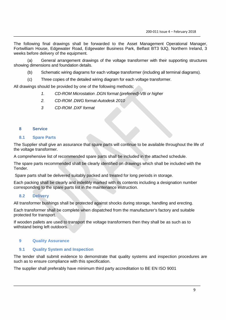
The following final drawings shall be forwarded to the Asset Management Operational Manager, Fortwilliam House, Edgewater Road, Edgewater Business Park, Belfast BT3 9JQ, Northern Ireland, 3 weeks before delivery of the equipment.
(a) General arrangement drawings of the voltage transformer with their supporting structures showing dimensions and foundation details.
(b) Schematic wiring diagrams for each voltage transformer (including all terminal diagrams).
(c) Three copies of the detailed wiring diagram for each voltage transformer.
All drawings should be provided by one of the following methods;
1. CD-ROM Microstation .DGN format (preferred)-V8i or higher
2. CD-ROM .DWG format-Autodesk 2010
3 CD-ROM .DXF format
8 Service
8.1 Spare Parts
The Supplier shall give an assurance that spare parts will continue to be available throughout the life of the voltage transformer.
A comprehensive list of recommended spare parts shall be included in the attached schedule.
The spare parts recommended shall be clearly identified on drawings which shall be included with the Tender.
Spare parts shall be delivered suitably packed and treated for long periods in storage.
Each packing shall be clearly and indelibly marked with its contents including a designation number corresponding to the spare parts list in the maintenance instruction.
8.2 Delivery
All transformer bushings shall be protected against shocks during storage, handling and erecting.
Each transformer shall be complete when dispatched from the manufacturer's factory and suitable protected for transport.
If wooden pallets are used to transport the voltage transformers then they shall be as such as to withstand being left outdoors.
9 Quality Assurance
9.1 Quality System and Inspection
The tender shall submit evidence to demonstrate that quality systems and inspection procedures are such as to ensure compliance with this specification.
The supplier shall preferably have minimum third party accreditation to BE EN ISO 9001
UNCONTROLLED W
HEN PRIN
TED

200-011 Issue 4 – February 2018
10
Representatives of NIE Networks may wish to witness routine, type and special tests at the manufacturer's factory and the successful tenderer shall be required to give adequate notice of the dates for the tests. (Minimum of 3 working weeks required).
9.2 Environment
NIE Networks is committed to protecting the environment in which it carries out its activities and to this end has obtained accreditation to BS EN ISO 14001. As part of this commitment NIE Networks would prefer manufacturers to be accredited to ISO 14001, but as a minimum, demonstrate that a suitable environmental management system and inspection procedures are in place.
UNCONTROLLED W
HEN PRIN
TED

200-011 Issue 4 – February 2018
11
10 Schedule of Requirements
ITEM EQUIPMENT QUANTITY
Item 1 Voltage Transformer (as per section 2)
Item 2 MCB Box (as per section 4)
Item 3 Structure (as per section 5)
Item 4 High Voltage VT Fusing INTERNAL
Item VT secondary winding requirements Required? No. of windings
1 Metering/Protection winding
(as per section 2.4)
1 Residual winding (as per section 2.5)
11 APPENDIX A
Voltage Transformer Details
1. Rated Primary Voltage: 33kV phase to phase
33kV/√3 phase to neutral
2. Rated Secondary Voltage: 110V phase to phase
63.5V phase to neutral
3. Rated Output:
Secondary Winding
Residual Winding
75 VA per phase
50 VA per phase
UNCONTROLLED W
HEN PRIN
TED

200-011 Issue 4 – February 2018
12
4. Accuracy Class:
Metering
Metering/Protection
Class 0.5
Class 0.5/6p
5. Rated Voltage Factor: 1.2 continuous, 1.9 for 30 seconds
6. Primary Winding Insulation:
Power Frequency
Lightning Impulse
95kV rms
170kV peak
7. Secondary Winding Insulation:
3kV for 1 minute
8. Bushing Insulation Requirements:
250kV
9. Creepage distance: Minimum of 25kV/mm at highest system voltage of 36kV
UNCONTROLLED W
HEN PRIN
TED