qtd20 - interoute · pdf fileqtd20.241 q-series 24v, 20a, dc input ... typ. 1.5a peak :...
TRANSCRIPT
QTD20.241 Q-Series 24V, 20A, DC INPUT
Mar 2012 / Rev. 1.2 DS-QTD20.241-EN All parameters are specified at 24V, 20A, 600Vdc input, 25°C ambient and after a 5 minutes run-in time unless otherwise noted.
www.pulspower.com Phone +49 89 9278 0 Germany
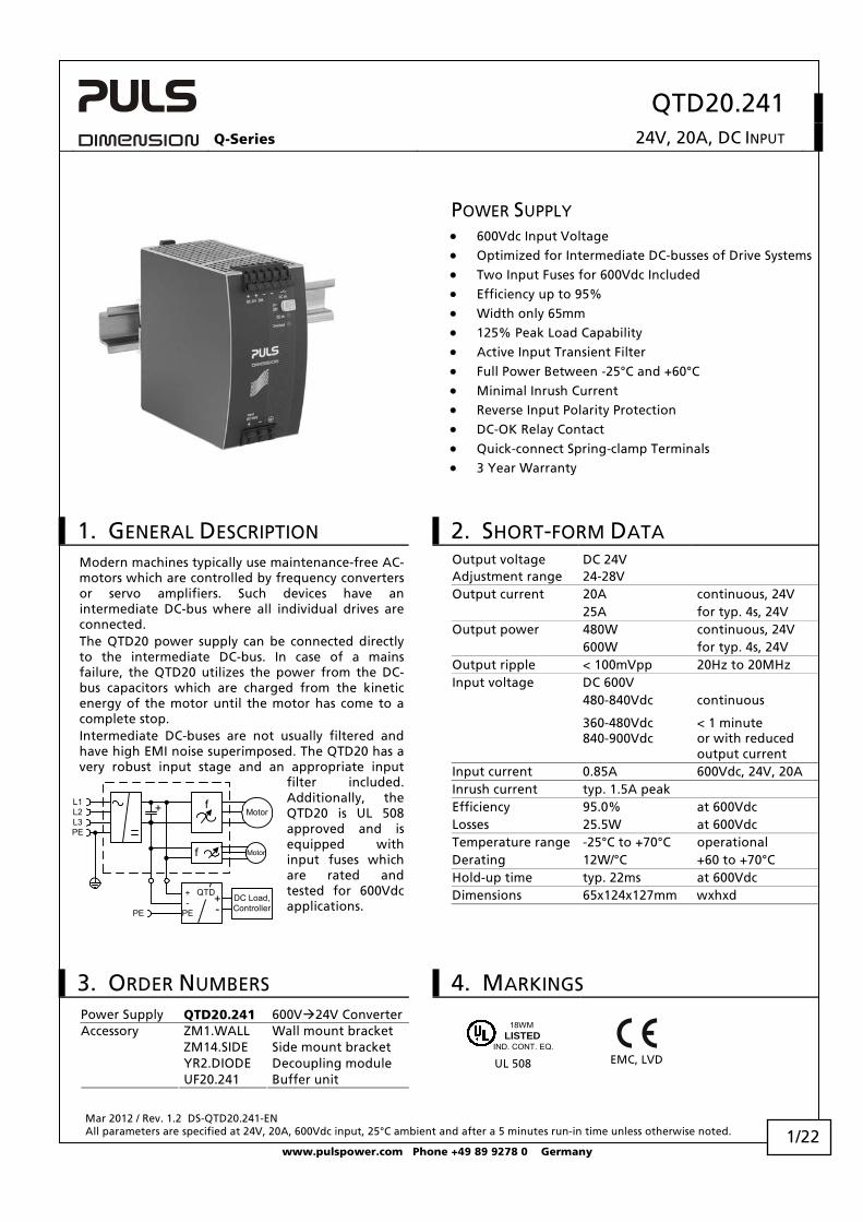
POWER SUPPLY • 600Vdc Input Voltage • Optimized for Intermediate DC-busses of Drive Systems • Two Input Fuses for 600Vdc Included • Efficiency up to 95% • Width only 65mm • 125% Peak Load Capability • Active Input Transient Filter • Full Power Between -25°C and +60°C • Minimal Inrush Current • Reverse Input Polarity Protection • DC-OK Relay Contact • Quick-connect Spring-clamp Terminals • 3 Year Warranty
1. GENERAL DESCRIPTION 2. SHORT-FORM DATA Output voltage DC 24V Adjustment range 24-28V Output current 20A continuous, 24V 25A for typ. 4s, 24V Output power 480W continuous, 24V 600W for typ. 4s, 24V Output ripple < 100mVpp 20Hz to 20MHz Input voltage DC 600V 480-840Vdc continuous 360-480Vdc
840-900Vdc < 1 minute or with reduced output current
Input current 0.85A 600Vdc, 24V, 20A Inrush current typ. 1.5A peak Efficiency 95.0% at 600Vdc Losses 25.5W at 600Vdc Temperature range -25°C to +70°C operational Derating 12W/°C +60 to +70°C Hold-up time typ. 22ms at 600Vdc Dimensions 65x124x127mm wxhxd
Modern machines typically use maintenance-free AC-motors which are controlled by frequency converters or servo amplifiers. Such devices have an intermediate DC-bus where all individual drives are connected. The QTD20 power supply can be connected directly to the intermediate DC-bus. In case of a mains failure, the QTD20 utilizes the power from the DC-bus capacitors which are charged from the kinetic energy of the motor until the motor has come to a complete stop. Intermediate DC-buses are not usually filtered and have high EMI noise superimposed. The QTD20 has a very robust input stage and an appropriate input
filter included. Additionally, the QTD20 is UL 508 approved and is equipped with input fuses which are rated and tested for 600Vdc applications.
L1L2L3PE
fMotor
PE
+
DC Load,Controller
QTD+-
+-
PE
f Motor
3. ORDER NUMBERS 4. MARKINGS Power Supply QTD20.241 600V 24V Converter
Accessory ZM1.WALL Wall mount bracket ZM14.SIDE Side mount bracket YR2.DIODE Decoupling module UF20.241 Buffer unit
IND. CONT. EQ.
18WMLISTED
UL 508
EMC, LVD
1/22
QTD20.241 Q-Series 24V, 20A, DC INPUT
Mar 2012 / Rev. 1.2 DS-QTD20.241-EN All parameters are specified at 24V, 20A, 600Vdc input, 25°C ambient and after a 5 minutes run-in time unless otherwise noted.
www.pulspower.com Phone +49 89 9278 0 Germany
INDEX PAGE INDEX PAGE
1. General Description ............................................1 20. Approvals.......................................................... 14 2. Short-form Data ..................................................1 21. Fulfilled Standards............................................ 14 3. Order Numbers....................................................1 22. Used Substances ............................................... 14 4. Markings..............................................................1 23. Physical Dimensions and Weight ..................... 15 5. Input Voltage ......................................................3 24. Installation and Operation Instructions .......... 15 6. Input Inrush Current ...........................................4 25. Accessories ........................................................ 16 7. Output .................................................................5 26. Application Notes............................................. 17 8. Hold-up Time.......................................................7 26.1. Repetitive Pulse Loading........................ 17 9. DC-OK Relay Contact ..........................................7 26.2. Back-feeding Loads ................................ 18 10. Efficiency and Power Losses................................8 26.3. Charging of Batteries............................. 18 11. Functional Diagram.............................................9 26.4. Output Circuit Breakers ......................... 19 12. Front Side and User Elements.............................9 26.5. Parallel Use to Increase Output Power . 20 13. Terminals and Wiring........................................10 26.6. Parallel Use for Redundancy.................. 20 14. Reliability ...........................................................10 26.7. Daisy Chaining of Outputs..................... 20 15. EMC....................................................................11 26.8. Series Operation..................................... 21 16. Environment ......................................................12 26.9. Inductive and Capacitive Loads ............. 21 17. Protection Features ...........................................13 26.10. Use in a Tightly Sealed Enclosure .......... 21 18. Safety .................................................................13 26.11. Mounting Orientations.......................... 22 19. Dielectric Strength ............................................13
INTENDED USE The power supply shall only be installed and put into operation by qualified personnel.
This power supply is designed for installation in an enclosure and is intended for the general use, such as in industrial control, office, communication, and instrumentation equipment. Do not use this device in aircraft, trains and nuclear equipment, where malfunctioning of the power supply may cause severe personal injury or threaten human life.
TERMINOLOGY AND ABREVIATIONS PE and symbol PE is the abbreviation for Protective Earth and has the same meaning as the symbol .
Earth, Ground This document uses the term “earth” which is the same as the U.S. term “ground”.
T.b.d. To be defined, value or description will follow later.
DC 600V A figure displayed with the AC or DC before the value represents a nominal voltage with standard tolerances (usually ±15%) included. E.g.: DC 12V describes a 12V battery regardless whether it is charged (13.7V) or discharged (10V)
600Vdc A figure with the unit (Vdc) at the end is a value which is used during testing without any additional tolerances included.
DISCLAIMER The information presented in this document is believed to be accurate and reliable and may change without notice.
2/22
QTD20.241 Q-Series 24V, 20A, DC INPUT
Mar 2012 / Rev. 1.2 DS-QTD20.241-EN All parameters are specified at 24V, 20A, 600Vdc input, 25°C ambient and after a 5 minutes run-in time unless otherwise noted.
www.pulspower.com Phone +49 89 9278 0 Germany
5. INPUT VOLTAGE
Input nom. DC 600V Input voltage range 480-840Vdc continuous operation 360-480Vdc max. 60 seconds or with de-rating according to Fig. 7-2
840-900Vdc max. 60 seconds or with de-rating according to Fig. 7-2
1000Vdc Absolute maximum input voltage with no damage to the
power supply. Above 900Vdc, the output will switch off and will turn-on again when the voltage falls below 850V.
Allowed voltage between input and earth (ground)
max. 600V R.M.S. continuously allowed
max. ±900V peak value, allowed for transients
Slew rate for voltage between input and earth (ground)
max. 1000V/μs
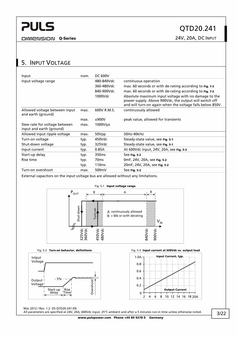
Allowed input ripple voltage max. 50Vpp 50Hz-40kHz Turn-on voltage typ. 450Vdc Steady-state value, see Fig. 5-1
Shut-down voltage typ. 325Vdc Steady-state value, see Fig. 5-1
Input current typ. 0.85A At 600Vdc input, 24V, 20A, see Fig. 5-3
Start-up delay typ. 350ms See Fig. 5-2
Rise time typ. 70ms 0mF, 24V, 20A, see Fig. 5-2
typ. 110ms 20mF, 24V, 20A, see Fig. 5-2
Turn-on overshoot max. 500mV See Fig. 5-2
External capacitors on the input voltage bus are allowed without any limitations.
Fig. 5-1 Input voltage range
Turn
-on
450V
dc
VIN
POUT
900V
dc
Shu
t-d
ow
n
840V
dc
325V
dc
480V
dc
360V
dc
A: continuously allowedB: < 60s or with derating
B A B
Fig. 5-2 Turn-on behavior, definitions Fig. 5-3 Input current at 600Vdc vs. output load
Start-updelay
RiseTime O
vers
ho
ot- 5%Output
Voltage
IntputVoltage
20A2 4 6 8 10 12 14 16 180
0.2
0.4
0.6
1.0A
0.8
Output Current
Input Current, typ.
3/22
QTD20.241 Q-Series 24V, 20A, DC INPUT
Mar 2012 / Rev. 1.2 DS-QTD20.241-EN All parameters are specified at 24V, 20A, 600Vdc input, 25°C ambient and after a 5 minutes run-in time unless otherwise noted.
www.pulspower.com Phone +49 89 9278 0 Germany
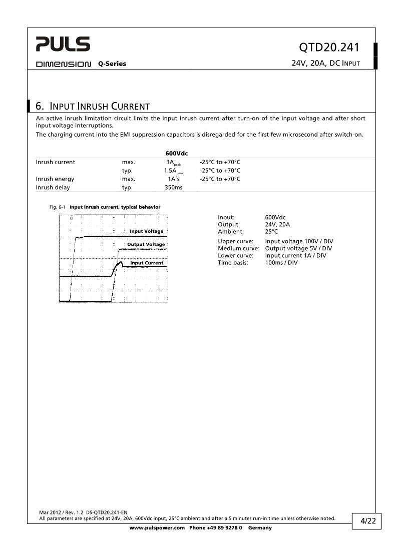
6. INPUT INRUSH CURRENT An active inrush limitation circuit limits the input inrush current after turn-on of the input voltage and after short input voltage interruptions.
The charging current into the EMI suppression capacitors is disregarded for the first few microsecond after switch-on.
600Vdc Inrush current max. 3Apeak -25°C to +70°C typ. 1.5Apeak -25°C to +70°C Inrush energy max. 1A2s -25°C to +70°C Inrush delay typ. 350ms
Fig. 6-1 Input inrush current, typical behavior
Input Current
Input Voltage
Output Voltage
Input: 600Vdc Output: 24V, 20A Ambient: 25°C
Upper curve: Input voltage 100V / DIV Medium curve: Output voltage 5V / DIV Lower curve: Input current 1A / DIV Time basis: 100ms / DIV
4/22
QTD20.241 Q-Series 24V, 20A, DC INPUT
Mar 2012 / Rev. 1.2 DS-QTD20.241-EN All parameters are specified at 24V, 20A, 600Vdc input, 25°C ambient and after a 5 minutes run-in time unless otherwise noted.
www.pulspower.com Phone +49 89 9278 0 Germany 5/22
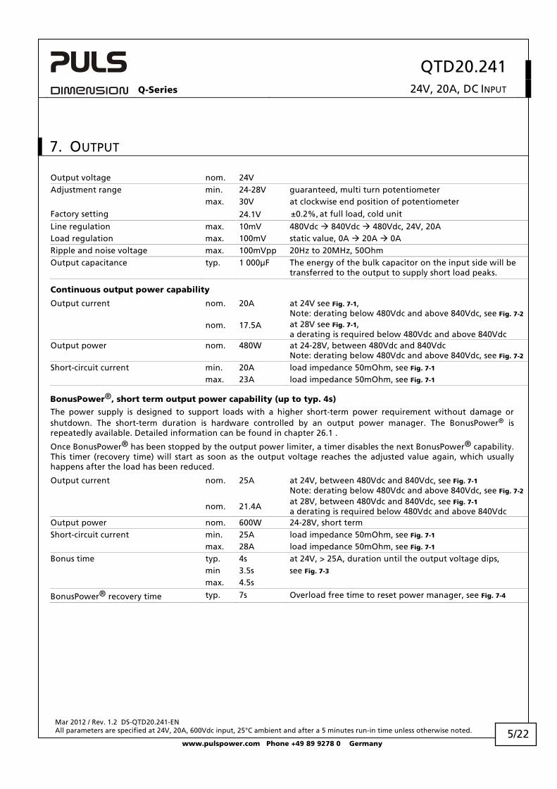
7. OUTPUT
Output voltage nom. 24V Adjustment range min. 24-28V guaranteed, multi turn potentiometer max. 30V at clockwise end position of potentiometer Factory setting 24.1V ±0.2%, at full load, cold unit
Line regulation max. 10mV 480Vdc 840Vdc 480Vdc, 24V, 20A Load regulation max. 100mV static value, 0A 20A 0A Ripple and noise voltage max. 100mVpp 20Hz to 20MHz, 50Ohm
Output capacitance typ. 1 000μF The energy of the bulk capacitor on the input side will be
transferred to the output to supply short load peaks.
Continuous output power capability
Output current nom. 20A at 24V see Fig. 7-1,
Note: derating below 480Vdc and above 840Vdc, see Fig. 7-2
nom. 17.5A at 28V see Fig. 7-1, a derating is required below 480Vdc and above 840Vdc
Output power nom. 480W at 24-28V, between 480Vdc and 840Vdc
Note: derating below 480Vdc and above 840Vdc, see Fig. 7-2
Short-circuit current min. 20A load impedance 50mOhm, see Fig. 7-1
max. 23A load impedance 50mOhm, see Fig. 7-1
BonusPower®, short term output power capability (up to typ. 4s)
The power supply is designed to support loads with a higher short-term power requirement without damage or shutdown. The short-term duration is hardware controlled by an output power manager. The BonusPower® is repeatedly available. Detailed information can be found in chapter 26.1 .
Once BonusPower® has been stopped by the output power limiter, a timer disables the next BonusPower® capability. This timer (recovery time) will start as soon as the output voltage reaches the adjusted value again, which usually happens after the load has been reduced.
Output current nom. 25A at 24V, between 480Vdc and 840Vdc, see Fig. 7-1
Note: derating below 480Vdc and above 840Vdc, see Fig. 7-2
nom. 21.4A at 28V, between 480Vdc and 840Vdc, see Fig. 7-1 a derating is required below 480Vdc and above 840Vdc
Output power nom. 600W 24-28V, short term Short-circuit current min. 25A load impedance 50mOhm, see Fig. 7-1
max. 28A load impedance 50mOhm, see Fig. 7-1
Bonus time typ. 4s at 24V, > 25A, duration until the output voltage dips, min 3.5s see Fig. 7-3
max. 4.5s
BonusPower® recovery time typ. 7s Overload free time to reset power manager, see Fig. 7-4
QTD20.241 Q-Series 24V, 20A, DC INPUT
Mar 2012 / Rev. 1.2 DS-QTD20.241-EN All parameters are specified at 24V, 20A, 600Vdc input, 25°C ambient and after a 5 minutes run-in time unless otherwise noted.
www.pulspower.com Phone +49 89 9278 0 Germany
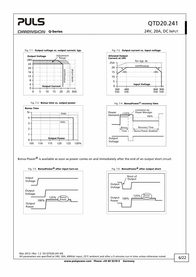
Fig. 7-1 Output voltage vs. output current, typ. Fig. 7-2 Output current vs. input voltage
Output Voltage
00 5 10 20 25
4
8
12
28V
16
20
24
15 30A
Output Current
s ho
r t-t erm
AdjustmentRange
con
tinu
ou
s
Allowed OutputCurrent at 24V
0900Vdc
5
10
15
20
25Acontinuous
for typ. 4s
840Vdc
360Vdc
480Vdc
Input Voltage
<60s<60s
Fig. 7-3 Bonus time vs. output power Fig. 7-4 BonusPower® recovery time
max.
Bonus Time
0105 110 115 120 125 130%
Output Power
1
2
3
4
5s
min.
PowerDemand
OutputVoltage
Limitation byPower Manager
Bonus Power disabled
Recovery Time
100%<125%
Bonus
Time
Bonus Power® is available as soon as power comes on and immediately after the end of an output short circuit.
Fig. 7-5 BonusPower® after input turn-on Fig. 7-6 BonusPower® after output short
100%
OutputVoltage
IntputVoltage
BonusPower
OutputPower
125%
Short ofOutput
100%
OutputVoltage
BonusPowerOutput
Power
125%
6/22
QTD20.241 Q-Series 24V, 20A, DC INPUT
Mar 2012 / Rev. 1.2 DS-QTD20.241-EN All parameters are specified at 24V, 20A, 600Vdc input, 25°C ambient and after a 5 minutes run-in time unless otherwise noted.
www.pulspower.com Phone +49 89 9278 0 Germany
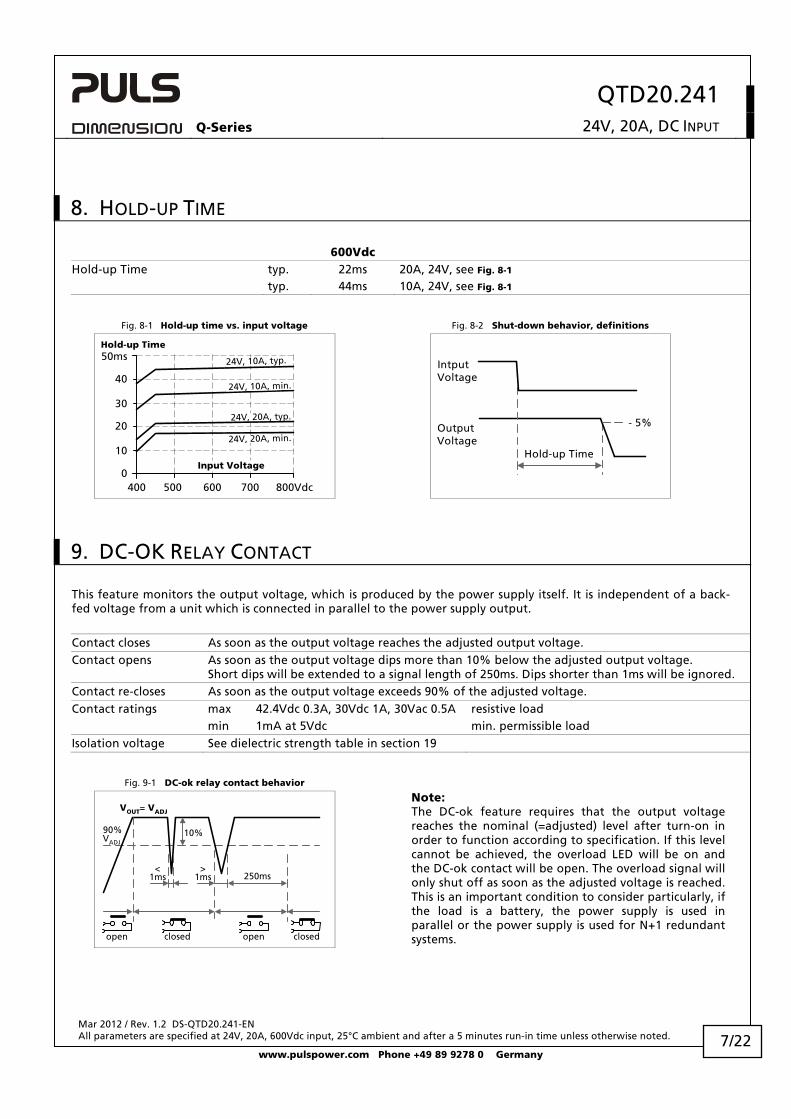
8. HOLD-UP TIME
600Vdc Hold-up Time typ. 22ms 20A, 24V, see Fig. 8-1
typ. 44ms 10A, 24V, see Fig. 8-1
Fig. 8-1 Hold-up time vs. input voltage Fig. 8-2 Shut-down behavior, definitions
0
10
20
30
40
50ms
400 500 600 700 800Vdc
Input Voltage
Hold-up Time
24V, 10A, typ.
24V, 20A, typ.
24V, 10A, min.
24V, 20A, min.
- 5%
Hold-up Time
OutputVoltage
IntputVoltage
9. DC-OK RELAY CONTACT
This feature monitors the output voltage, which is produced by the power supply itself. It is independent of a back-fed voltage from a unit which is connected in parallel to the power supply output.
Contact closes As soon as the output voltage reaches the adjusted output voltage.
Contact opens As soon as the output voltage dips more than 10% below the adjusted output voltage. Short dips will be extended to a signal length of 250ms. Dips shorter than 1ms will be ignored.
Contact re-closes As soon as the output voltage exceeds 90% of the adjusted voltage. Contact ratings max 42.4Vdc 0.3A, 30Vdc 1A, 30Vac 0.5A resistive load min 1mA at 5Vdc min. permissible load Isolation voltage See dielectric strength table in section 19
Fig. 9-1 DC-ok relay contact behavior
250ms
90%VADJ
<1ms
10%
open
VOUT= VADJ
openclosed closed
>1ms
Note: The DC-ok feature requires that the output voltage reaches the nominal (=adjusted) level after turn-on in order to function according to specification. If this level cannot be achieved, the overload LED will be on and the DC-ok contact will be open. The overload signal will only shut off as soon as the adjusted voltage is reached. This is an important condition to consider particularly, if the load is a battery, the power supply is used in parallel or the power supply is used for N+1 redundant systems.
7/22
QTD20.241 Q-Series 24V, 20A, DC INPUT
Mar 2012 / Rev. 1.2 DS-QTD20.241-EN All parameters are specified at 24V, 20A, 600Vdc input, 25°C ambient and after a 5 minutes run-in time unless otherwise noted.
www.pulspower.com Phone +49 89 9278 0 Germany
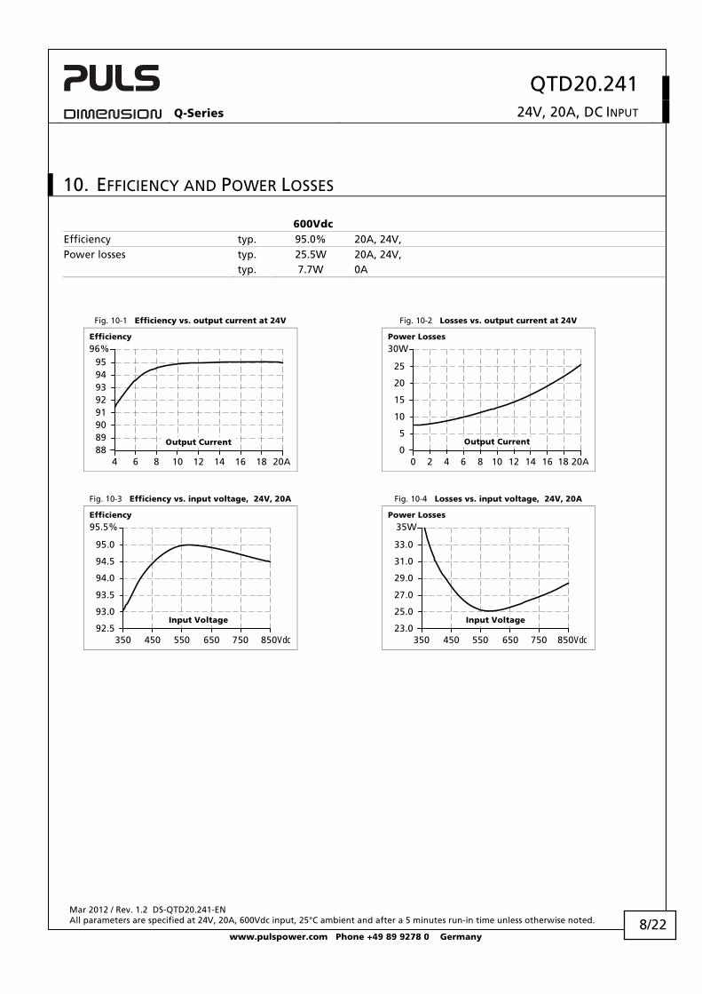
10. EFFICIENCY AND POWER LOSSES
600Vdc Efficiency typ. 95.0% 20A, 24V, Power losses typ. 25.5W 20A, 24V, typ. 7.7W 0A
Fig. 10-1 Efficiency vs. output current at 24V Fig. 10-2 Losses vs. output current at 24V
Efficiency
4 6 8 10 12 14 16 18 20A8889909192939495
96%
Output Current
Power Losses
0 2 4 6 8 10 12 14 20A0
5
10
15
20
Output Current
25
30W
16 18
Fig. 10-3 Efficiency vs. input voltage, 24V, 20A Fig. 10-4 Losses vs. input voltage, 24V, 20A
Efficiency
350 450 650 750 850Vdc92.5
93.0
93.5
94.0
94.5
95.0
95.5%
Input Voltage
550
Power Losses
350 450 550 650 850Vdc23.0
25.0
27.0
29.0
31.0
33.0
35W
750
Input Voltage
8/22
QTD20.241 Q-Series 24V, 20A, DC INPUT
Mar 2012 / Rev. 1.2 DS-QTD20.241-EN All parameters are specified at 24V, 20A, 600Vdc input, 25°C ambient and after a 5 minutes run-in time unless otherwise noted.
www.pulspower.com Phone +49 89 9278 0 Germany
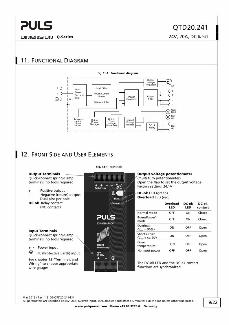
11. FUNCTIONAL DIAGRAM
Fig. 11-1 Functional diagram
++
--
VOUT
DCok
OutputOver-
VoltageProtection
Input Filter
Inrush CurrentLimiter
Transient Filter
InputFuses(in + and -pole)
OutputVoltage
Regulator
PowerConverter
OutputFilter
DC okRelay
OutputVoltageMonitor
OutputPower
Manager
Temper-atureShut-down
Over-load
DCok
+-
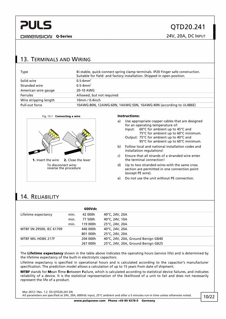
12. FRONT SIDE AND USER ELEMENTS
Fig. 12-1 Front side
Output voltage potentiometer (multi turn potentiometer) Open the flap to set the output voltage. Factory setting: 24.1V
Output Terminals Quick-connect spring-clamp terminals, no tools required + Positive output - Negative (return) output Dual pins per pole DC ok Relay contact (NO-contact)
9/22
DC-ok LED (green) Overload LED (red)
Overload
LED DC-ok LED
DC-ok contact
Normal mode OFF ON Closed
BonusPower® mode
OFF ON Closed
Overload (VOUT < 90%) ON OFF Open
Short-circuit (VOUT = ca. 0V)
ON OFF Open
Over- temperature
ON OFF Open
Input Terminals Quick-connect spring-clamp terminals, no tools required + - Power input
PE (Protective Earth) input No input power OFF OFF Open
See chapter 13 “Terminals and Wiring” to choose appropriate wire gauges
The DC-ok LED and the DC-ok contact functions are synchronized
QTD20.241 Q-Series 24V, 20A, DC INPUT
Mar 2012 / Rev. 1.2 DS-QTD20.241-EN All parameters are specified at 24V, 20A, 600Vdc input, 25°C ambient and after a 5 minutes run-in time unless otherwise noted.
www.pulspower.com Phone +49 89 9278 0 Germany
13. TERMINALS AND WIRING
Type Bi-stable, quick-connect spring clamp terminals. IP20 Finger safe construction. Suitable for field- and factory installation. Shipped in open position.
Solid wire 0.5-6mm2 Stranded wire 0.5-4mm2 American wire gauge 20-10 AWG Ferrules Allowed, but not required Wire stripping length 10mm / 0.4inch Pull-out force 10AWG:80N, 12AWG:60N, 14AWG:50N, 16AWG:40N (according to UL486E)
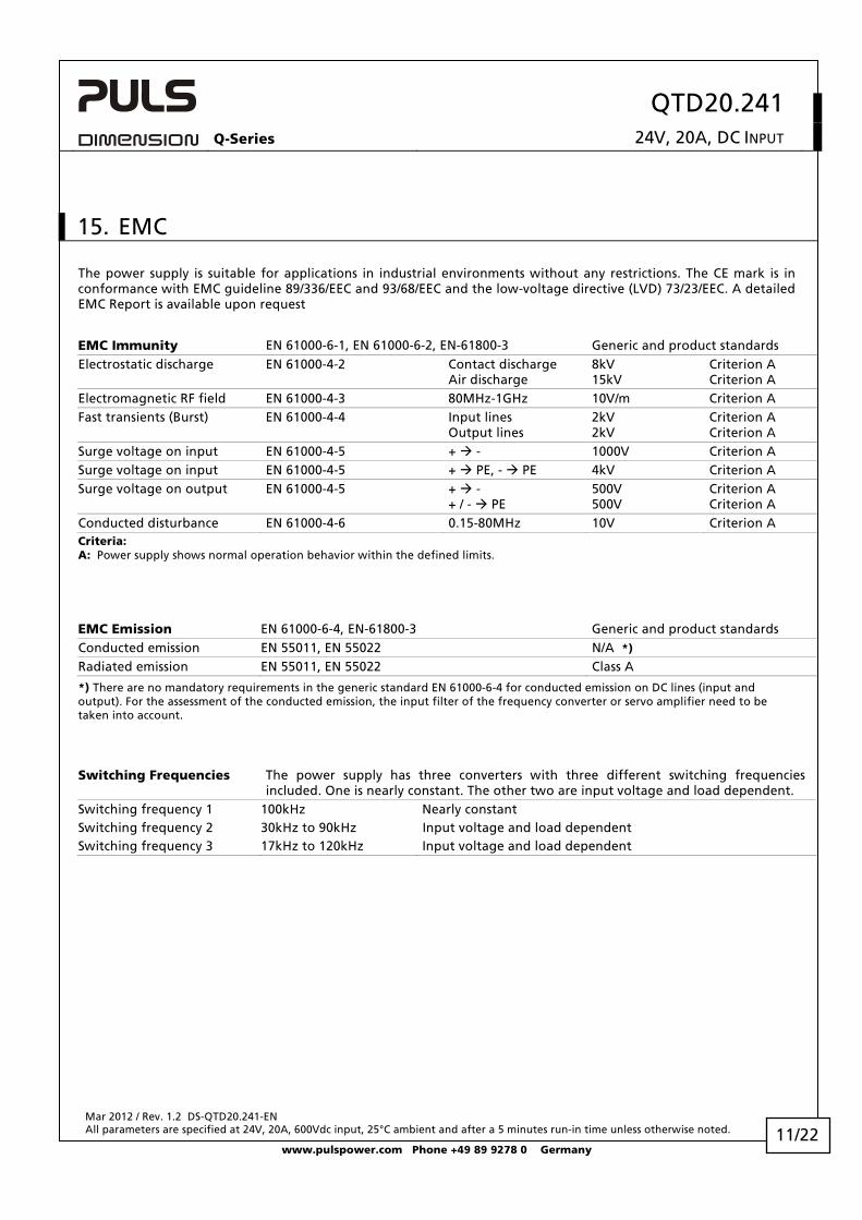
Fig. 13-1 Connecting a wire
1. Insert the wire 2. Close the lever
To disconnect wire:reverse the procedure
Instructions:
a) Use appropriate copper cables that are designed for an operating temperature of: Input: 60°C for ambient up to 45°C and 75°C for ambient up to 60°C minimum. Output: 75°C for ambient up to 40°C and 95°C for ambient up to 60°C minimum.
b) Follow local and national installation codes and installation regulations!
c) Ensure that all strands of a stranded wire enter the terminal connection!
d) Up to two stranded wires with the same cross section are permitted in one connection point (except PE wire).
e) Do not use the unit without PE connection.
14. RELIABILITY
600Vdc
Lifetime expectancy min. 42 000h 40°C, 24V, 20A min. 77 500h 40°C, 24V, 10A min. 119 000h 25°C, 24V, 20A MTBF SN 29500, IEC 61709 446 000h 40°C, 24V, 20A 801 000h 25°C, 24V, 20A MTBF MIL HDBK 217F 204 000h 40°C, 24V, 20A, Ground Benign GB40 267 000h 25°C, 24V, 20A, Ground Benign GB25
The Lifetime expectancy shown in the table above indicates the operating hours (service life) and is determined by the lifetime expectancy of the built-in electrolytic capacitors.
Lifetime expectancy is specified in operational hours and is calculated according to the capacitor’s manufacturer specification. The prediction model allows a calculation of up to 15 years from date of shipment.
MTBF stands for Mean Time Between Failure, which is calculated according to statistical device failures, and indicates reliability of a device. It is the statistical representation of the likelihood of a unit to fail and does not necessarily represent the life of a product.
10/22
QTD20.241 Q-Series 24V, 20A, DC INPUT
Mar 2012 / Rev. 1.2 DS-QTD20.241-EN All parameters are specified at 24V, 20A, 600Vdc input, 25°C ambient and after a 5 minutes run-in time unless otherwise noted.
www.pulspower.com Phone +49 89 9278 0 Germany 11/22
15. EMC
The power supply is suitable for applications in industrial environments without any restrictions. The CE mark is in conformance with EMC guideline 89/336/EEC and 93/68/EEC and the low-voltage directive (LVD) 73/23/EEC. A detailed EMC Report is available upon request
EMC Immunity EN 61000-6-1, EN 61000-6-2, EN-61800-3 Generic and product standards
Electrostatic discharge EN 61000-4-2 Contact discharge
Air discharge 8kV 15kV
Criterion A Criterion A
Electromagnetic RF field EN 61000-4-3 80MHz-1GHz 10V/m Criterion A
Fast transients (Burst) EN 61000-4-4 Input lines
Output lines 2kV 2kV
Criterion A Criterion A
Surge voltage on input EN 61000-4-5 + - 1000V Criterion A Surge voltage on input EN 61000-4-5 + PE, - PE 4kV Criterion A
Surge voltage on output EN 61000-4-5 + -
+ / - PE 500V 500V
Criterion A Criterion A
Conducted disturbance EN 61000-4-6 0.15-80MHz 10V Criterion A Criteria: A: Power supply shows normal operation behavior within the defined limits.
EMC Emission EN 61000-6-4, EN-61800-3 Generic and product standards Conducted emission EN 55011, EN 55022 N/A *) Radiated emission EN 55011, EN 55022 Class A
*) There are no mandatory requirements in the generic standard EN 61000-6-4 for conducted emission on DC lines (input and output). For the assessment of the conducted emission, the input filter of the frequency converter or servo amplifier need to be taken into account.
Switching Frequencies The power supply has three converters with three different switching frequencies included. One is nearly constant. The other two are input voltage and load dependent.
Switching frequency 1 100kHz Nearly constant Switching frequency 2 30kHz to 90kHz Input voltage and load dependent Switching frequency 3 17kHz to 120kHz Input voltage and load dependent
QTD20.241 Q-Series 24V, 20A, DC INPUT
Mar 2012 / Rev. 1.2 DS-QTD20.241-EN All parameters are specified at 24V, 20A, 600Vdc input, 25°C ambient and after a 5 minutes run-in time unless otherwise noted.
www.pulspower.com Phone +49 89 9278 0 Germany
16. ENVIRONMENT
Operational temperature -25°C to +70°C (-13°F to 158°F) Reduce output power above +60°C Output de-rating 12W/°C 60-70°C (140°F to 158°F), see Fig. 16-1
Storage temperature -40 to +85°C (-40°F to 185°F) Storage and transportation
Humidity 5 to 95% r.H. IEC 60068-2-30
Do not energize while condensation is present
Vibration sinusoidal 2-17.8Hz: ±1.6mm;
17.8-500Hz: 2g 2 hours / axis
IEC 60068-2-6
Vibration random 0.5m2(s3) 2 hours / axis
IEC 60068-2-64
Shock 30g 6ms, 20g 11ms
3 bumps / direction, 18 bumps in total
IEC 60068-2-27
Altitude 0 to 6000m (0 to 20 000ft) Reduce output power or ambient temperature above 2000m sea level.
Output de-rating (for altitude) 30W/1000m or 5°C/1000m above 2000m, see Fig. 16-2
Over-voltage category III EN 50178, altitudes up to 2000m II Altitudes from 2000m to 6000m Degree of pollution 2 EN 50178, non conductive
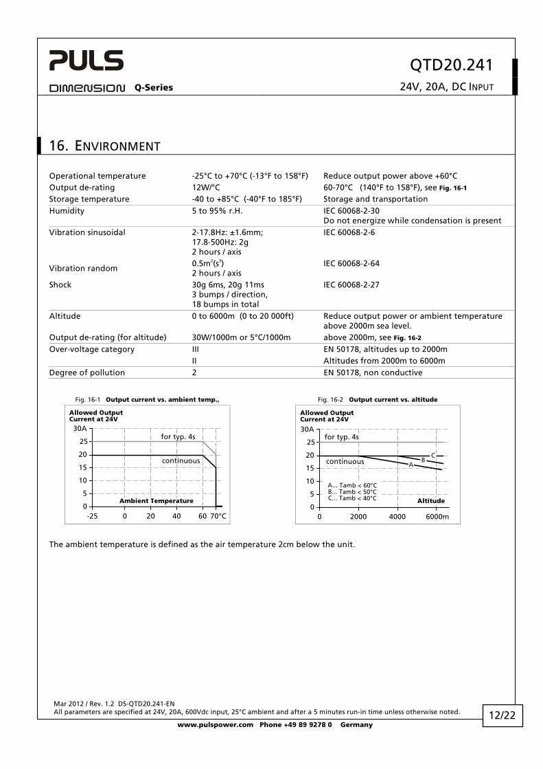
Fig. 16-1 Output current vs. ambient temp., Fig. 16-2 Output current vs. altitude
Allowed OutputCurrent at 24V
0-25 0 20 40 70°C
5
10
15
20
25
30A
continuous
60
Ambient Temperature
for typ. 4s
Allowed OutputCurrent at 24V
00 2000 4000 6000m
5
10
15
20
25
30A
continuous
Altitude
for typ. 4s
A... Tamb < 60°CB... Tamb < 50°CC... Tamb < 40°C
AB
C
The ambient temperature is defined as the air temperature 2cm below the unit.
12/22
QTD20.241 Q-Series 24V, 20A, DC INPUT
Mar 2012 / Rev. 1.2 DS-QTD20.241-EN All parameters are specified at 24V, 20A, 600Vdc input, 25°C ambient and after a 5 minutes run-in time unless otherwise noted.
www.pulspower.com Phone +49 89 9278 0 Germany
17. PROTECTION FEATURES
Output protection Electronically protected against overload, no load and short circuits *) Output over-voltage protection typ. 32Vdc
max. 35Vdc In case of an internal power supply fault, a redundant circuit limits the maximum output voltage. The output shuts-down and automatically attempts to restart.
Reverse input polarity protection included Unit does not start when input voltage is reversed Degree of protection IP 20 EN/IEC 60529 Penetration protection > 3.5mm e.g. screws, small parts Over-temperature protection yes Output shut-down with automatic restart Input transient protection MOV (Metal Oxide Varistor) and active transient filter
Internal input fuse 4A, midget size KLKD (Littelfuse)
The unit is equipped with two internal input fuses (+ line and - line) which protect the unit against internal short circuits and ground faults. The fuses are not user accessible. A tripping of an internal fuse is caused by an internal fault.
*) An audible noise may be heard during a no load, overload or short circuit event.
18. SAFETY
Input / output separation SELV IEC/EN 60204-1, EN 60950-1:2006 PELV EN 60204-1, EN 50178, IEC 60364-4-41 double or reinforced insulation Class of protection I PE (Protective Earth) connection required Isolation resistance > 5MOhm Input to output, 500Vdc PE resistance < 0.1Ohm Between housing and PE terminal
Touch current (leakage current) The leakage current which is produced by the power supply itself depends on the
input voltage ripple and need to be investigated in the final application. For a smooth DC input voltage, the produced leakage current is less than 100μA.
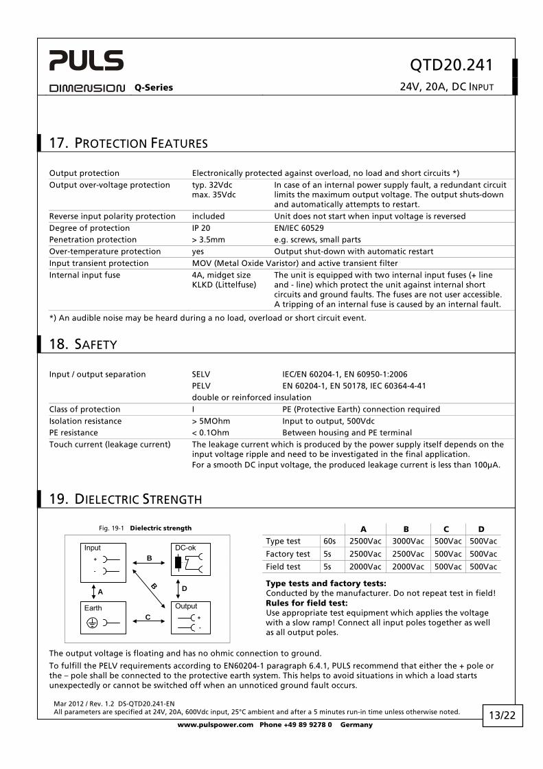
19. DIELECTRIC STRENGTH Fig. 19-1 Dielectric strength A B C D
Type test 60s 2500Vac 3000Vac 500Vac 500Vac
Factory test 5s 2500Vac 2500Vac 500Vac 500Vac
Field test 5s 2000Vac 2000Vac 500Vac 500Vac
A D
C
B
B+
Input DC-ok
Earth Output
-
+
-
Type tests and factory tests: Conducted by the manufacturer. Do not repeat test in field! Rules for field test: Use appropriate test equipment which applies the voltage with a slow ramp! Connect all input poles together as well as all output poles.
The output voltage is floating and has no ohmic connection to ground.
To fulfill the PELV requirements according to EN60204-1 paragraph 6.4.1, PULS recommend that either the + pole or the – pole shall be connected to the protective earth system. This helps to avoid situations in which a load starts unexpectedly or cannot be switched off when an unnoticed ground fault occurs.
13/22
QTD20.241 Q-Series 24V, 20A, DC INPUT
Mar 2012 / Rev. 1.2 DS-QTD20.241-EN All parameters are specified at 24V, 20A, 600Vdc input, 25°C ambient and after a 5 minutes run-in time unless otherwise noted.
www.pulspower.com Phone +49 89 9278 0 Germany
20. APPROVALS
UL 508
IND. CONT. EQ.
18WMLISTED
LISTED E198865 Industrial Control Equipment
21. FULFILLED STANDARDS
EN 61558-2-17 Safety of Power Transformers
EN/IEC 60204-1 Safety of Electrical Equipment of Machines
EN/IEC 61131-2 Programmable Controllers
EN 50178, IEC 62103 Electronic Equipment for Use in Power Installations
EN 61800-5 Adjustable speed electrical power drive systems, Safety requirements
EN 60950-1: 2006 Safety of Information Technology Equipment
22. USED SUBSTANCES
The unit does not release any silicone and is suitable for the use in paint shops.
Electrolytic capacitors included in this unit do not use electrolytes such as Quaternary Ammonium Salt Systems.
Plastic housings and other molded plastic materials are free of halogens, wires and cables are not PVC insulated.
The materials used in our production process do not include the following toxic chemicals: Polychlorinated Biphenyl (PCB), Polychlorinated Biphenyl (PCB), Pentachlorophenol (PCP), Polychlorinated naphthalene (PCN), Polybrominated Biphenyl (PBB), Polybrominated Biphenyl Oxide (PBO), Polybrominated Diphenyl Ether (PBDE), Polychlorinated Diphenyl Ether (PCDE), Polybrominated Diphenyl Oxide (PBDO), Cadmium, Asbestos, Mercury, Silica
14/22
QTD20.241 Q-Series 24V, 20A, DC INPUT
Mar 2012 / Rev. 1.2 DS-QTD20.241-EN All parameters are specified at 24V, 20A, 600Vdc input, 25°C ambient and after a 5 minutes run-in time unless otherwise noted.
www.pulspower.com Phone +49 89 9278 0 Germany
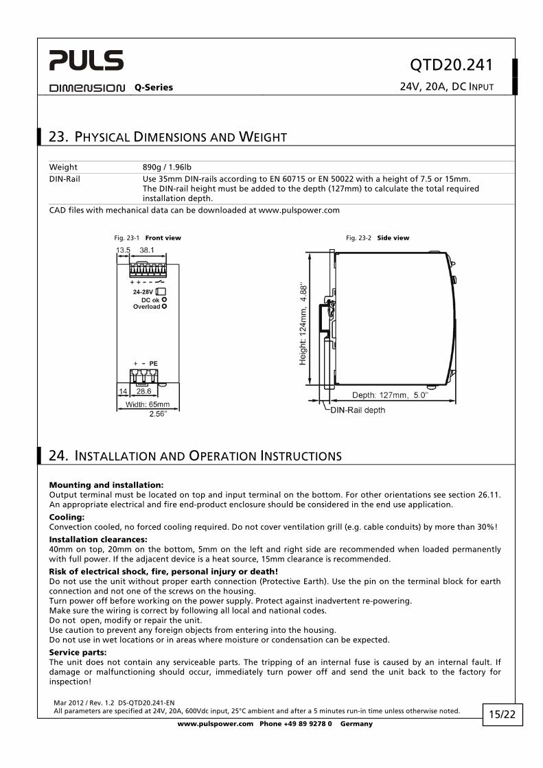
23. PHYSICAL DIMENSIONS AND WEIGHT
Weight 890g / 1.96lb DIN-Rail Use 35mm DIN-rails according to EN 60715 or EN 50022 with a height of 7.5 or 15mm.
The DIN-rail height must be added to the depth (127mm) to calculate the total required installation depth.
CAD files with mechanical data can be downloaded at www.pulspower.com
Fig. 23-1 Front view Fig. 23-2 Side view
24. INSTALLATION AND OPERATION INSTRUCTIONS
Mounting and installation: Output terminal must be located on top and input terminal on the bottom. For other orientations see section 26.11. An appropriate electrical and fire end-product enclosure should be considered in the end use application.
Cooling: Convection cooled, no forced cooling required. Do not cover ventilation grill (e.g. cable conduits) by more than 30%!
Installation clearances: 40mm on top, 20mm on the bottom, 5mm on the left and right side are recommended when loaded permanently with full power. If the adjacent device is a heat source, 15mm clearance is recommended.
Risk of electrical shock, fire, personal injury or death! Do not use the unit without proper earth connection (Protective Earth). Use the pin on the terminal block for earth connection and not one of the screws on the housing. Turn power off before working on the power supply. Protect against inadvertent re-powering. Make sure the wiring is correct by following all local and national codes. Do not open, modify or repair the unit. Use caution to prevent any foreign objects from entering into the housing. Do not use in wet locations or in areas where moisture or condensation can be expected.
Service parts: The unit does not contain any serviceable parts. The tripping of an internal fuse is caused by an internal fault. If damage or malfunctioning should occur, immediately turn power off and send the unit back to the factory for inspection!
15/22
QTD20.241 Q-Series 24V, 20A, DC INPUT
Mar 2012 / Rev. 1.2 DS-QTD20.241-EN All parameters are specified at 24V, 20A, 600Vdc input, 25°C ambient and after a 5 minutes run-in time unless otherwise noted.
www.pulspower.com Phone +49 89 9278 0 Germany
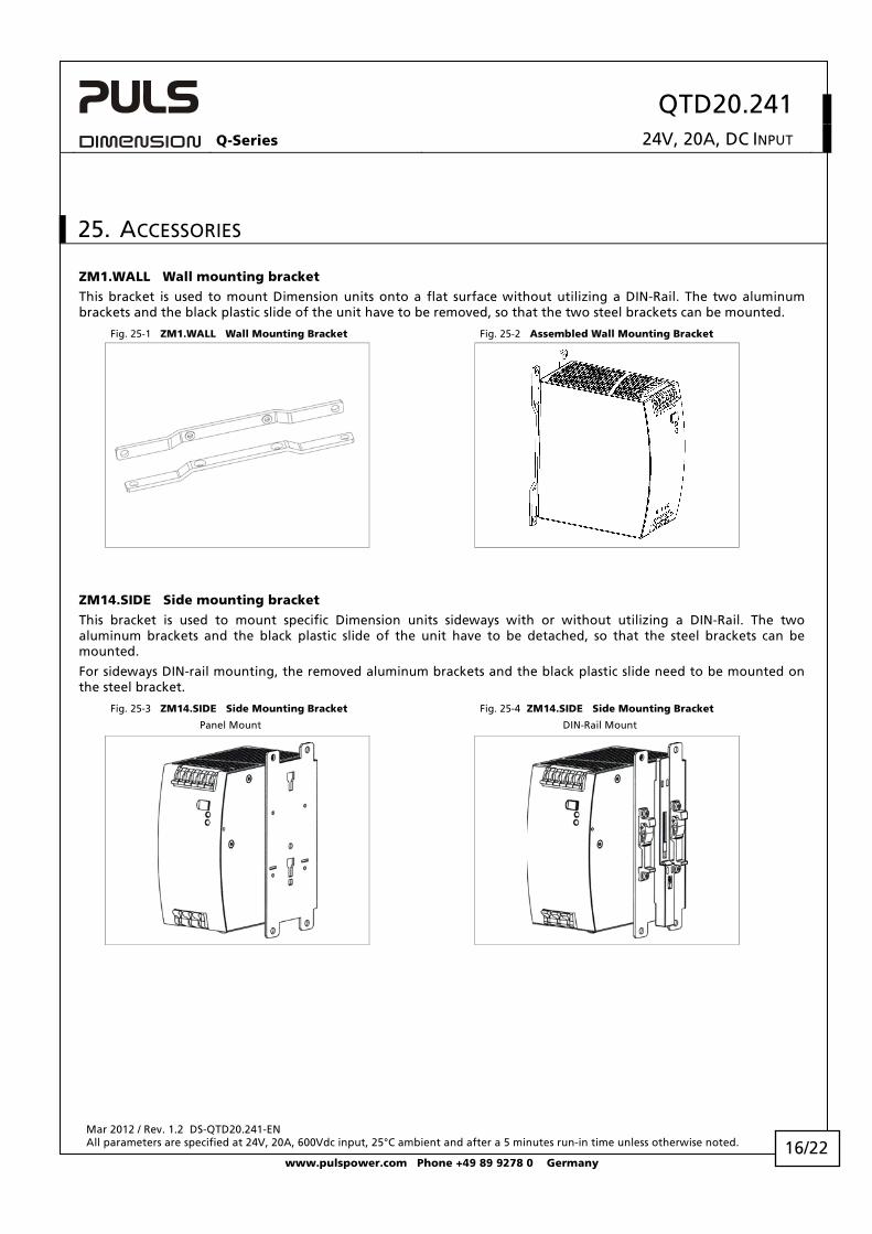
25. ACCESSORIES
ZM1.WALL Wall mounting bracket
This bracket is used to mount Dimension units onto a flat surface without utilizing a DIN-Rail. The two aluminum brackets and the black plastic slide of the unit have to be removed, so that the two steel brackets can be mounted.
Fig. 25-1 ZM1.WALL Wall Mounting Bracket Fig. 25-2 Assembled Wall Mounting Bracket
ZM14.SIDE Side mounting bracket
This bracket is used to mount specific Dimension units sideways with or without utilizing a DIN-Rail. The two aluminum brackets and the black plastic slide of the unit have to be detached, so that the steel brackets can be mounted.
For sideways DIN-rail mounting, the removed aluminum brackets and the black plastic slide need to be mounted on the steel bracket.
Fig. 25-3 ZM14.SIDE Side Mounting Bracket
Panel Mount
Fig. 25-4 ZM14.SIDE Side Mounting Bracket
DIN-Rail Mount
16/22

QTD20.241 Q-Series 24V, 20A, DC INPUT
Mar 2012 / Rev. 1.2 DS-QTD20.241-EN All parameters are specified at 24V, 20A, 600Vdc input, 25°C ambient and after a 5 minutes run-in time unless otherwise noted.
www.pulspower.com Phone +49 89 9278 0 Germany
26. APPLICATION NOTES
26.1. REPETITIVE PULSE LOADING Typically, a load current is not constant as it varies over time. For pulse load compatibility the following rules must be met:
a) The pulse power demand must be below 125% of the nominal power. b) The duration of the pulse power must be shorter than the allowed Bonus Time. (see output section) c) The average (R.M.S.) output current must be below the specified continuous output current.
If the R.M.S. current is higher, the unit will respond with a thermal shut-down after a period of time. Use the "Max. Duty Cycle Curve" (Fig. 26-2) to check if the average output current is below the nominal current.
d) The duty cycle must be below 0.75. e) For altitudes higher than 2000m reduce the pulse loading (15W/1000m) or the ambient temperature (5°C/1000m)
Fig. 26-1 Repetitive pulse loads, definitions Fig. 26-2 Max. Duty Cycle Curve
100%
PPEAK TPEAK
P0
T0max.125%
125%1000
0.2
0.4
0.6
0.75
Duty Cycle
105 110 115 120
PPEAK
P0 = 10%P0 = 50%P0 = 75%
P0 = 100%
P0 Base load (W) PPEAK Pulse load (above 100%) T0 Duration between pulses (s) TPEAK Pulse duration (s)
DutyCycleT0 =
Tpeak - (DutyCycle x Tpeak)
Tpeak + T0
TpeakDutyCycle =
Utilizing the Max. Duty Cycle Curve:
Example to determine the repetition rate of pulses without dipping of the output voltage:
Parameters of application: Pulse length of TPEAK = 1s Steady state load P0=120W (= 50% of IRATED) Peak load PPEAK = 600W (= 125% of IRATED)
Determining the repetition rate: 1) make a vertical line at PPEAK = 125% 2) make a horizontal line where the vertical line crosses the P0 = 50% curve 3) Read the Max. Duty Cycle from the Duty Cycle-axis (= 0.37) 4) Calculate the min. pause (base load) length T0 :
DutyCycleT0 =
Tpeak - (DutyCycle x Tpeak)=
0.37
1s - (0.37 x 1s)= 1.7s
5) Pulse length = 1s, min. pause length = 1.7s 6) Max. repetition rate = pulse length +pause length = 2.7s
More examples for pulse load compatibility:
PPEAK P0 TPEAK T0 PPEAK P0 TPEAK T0
600W 480W 1s >25s 600W 240W 0.1s >0.16s 600W 0W 1s >1.3s 600W 240W 1s >1.6s 540W 240W 1s > 0,75s 600W 240W 3s >4.9s
17/22
QTD20.241 Q-Series 24V, 20A, DC INPUT
Mar 2012 / Rev. 1.2 DS-QTD20.241-EN All parameters are specified at 24V, 20A, 600Vdc input, 25°C ambient and after a 5 minutes run-in time unless otherwise noted.
www.pulspower.com Phone +49 89 9278 0 Germany 18/22
26.2. BACK-FEEDING LOADS Loads such as decelerating motors and inductors can feed voltage back to the power supply. This feature is also called return voltage immunity or resistance against Back- E.M.F. (Electro Magnetic Force).
This power supply is resistant and does not show adverse effects when a load feeds back voltage to the power supply. It does not matter, whether the power supply is on or off.
The maximum allowed feed back voltage is 34Vdc. The absorbing energy can be calculated according to the built-in large sized output capacitor which is specified in chapter 7.
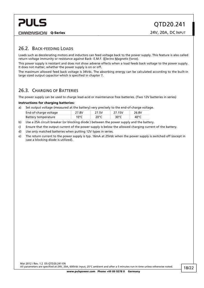
26.3. CHARGING OF BATTERIES The power supply can be used to charge lead-acid or maintenance free batteries. (Two 12V batteries in series)
Instructions for charging batteries:
a) Set output voltage (measured at the battery) very precisely to the end-of-charge voltage.
End-of-charge voltage 27.8V 27.5V 27.15V 26.8V Battery temperature 10°C 20°C 30°C 40°C
b) Use a 25A circuit breaker (or blocking diode ) between the power supply and the battery.
c) Ensure that the output current of the power supply is below the allowed charging current of the battery.
d) Use only matched batteries when putting 12V types in series.
e) The return current to the power supply is typ. 16mA at 25Vdc when the power supply is switched off (except in case a blocking diode is utilized).
QTD20.241 Q-Series 24V, 20A, DC INPUT
Mar 2012 / Rev. 1.2 DS-QTD20.241-EN All parameters are specified at 24V, 20A, 600Vdc input, 25°C ambient and after a 5 minutes run-in time unless otherwise noted.
www.pulspower.com Phone +49 89 9278 0 Germany
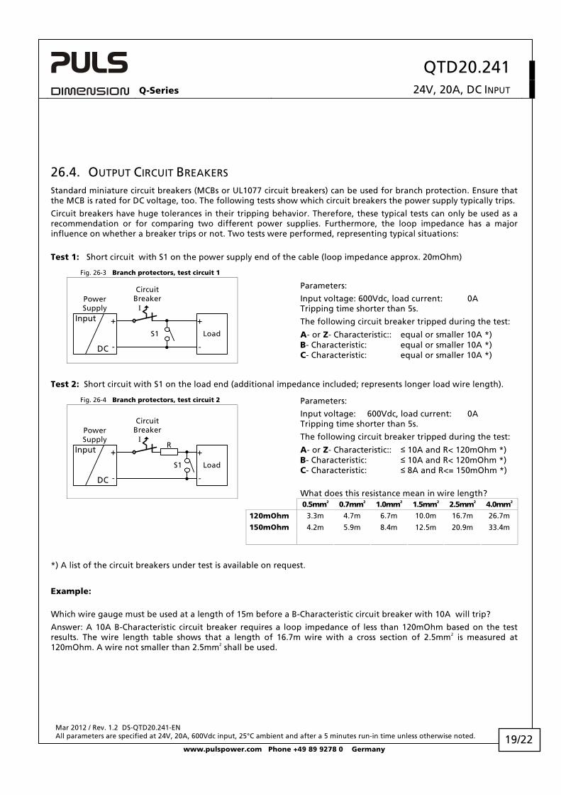
26.4. OUTPUT CIRCUIT BREAKERS Standard miniature circuit breakers (MCBs or UL1077 circuit breakers) can be used for branch protection. Ensure that the MCB is rated for DC voltage, too. The following tests show which circuit breakers the power supply typically trips.
Circuit breakers have huge tolerances in their tripping behavior. Therefore, these typical tests can only be used as a recommendation or for comparing two different power supplies. Furthermore, the loop impedance has a major influence on whether a breaker trips or not. Two tests were performed, representing typical situations:
Test 1: Short circuit with S1 on the power supply end of the cable (loop impedance approx. 20mOhm)
Fig. 26-3 Branch protectors, test circuit 1
CircuitBreakerPower
SupplyInput
DC
+
-
I
Load
+
-
S1
Parameters:
Input voltage: 600Vdc, load current: 0A Tripping time shorter than 5s.
The following circuit breaker tripped during the test:
A- or Z- Characteristic:: equal or smaller 10A *) B- Characteristic: equal or smaller 10A *) C- Characteristic: equal or smaller 10A *)
Test 2: Short circuit with S1 on the load end (additional impedance included; represents longer load wire length).
Fig. 26-4 Branch protectors, test circuit 2
R
CircuitBreakerPower
SupplyInput
DC
+
-
I
S1 Load
+
-
Parameters:
Input voltage: 600Vdc, load current: 0A Tripping time shorter than 5s.
The following circuit breaker tripped during the test:
A- or Z- Characteristic:: ≤ 10A and R< 120mOhm *) B- Characteristic: ≤ 10A and R< 120mOhm *) C- Characteristic: ≤ 8A and R<= 150mOhm *)
What does this resistance mean in wire length?
0.5mm2 0.7mm2 1.0mm2 1.5mm2 2.5mm2 4.0mm2
120mOhm 3.3m 4.7m 6.7m 10.0m 16.7m 26.7m
150mOhm 4.2m 5.9m 8.4m 12.5m 20.9m 33.4m
*) A list of the circuit breakers under test is available on request.
Example:
Which wire gauge must be used at a length of 15m before a B-Characteristic circuit breaker with 10A will trip?
Answer: A 10A B-Characteristic circuit breaker requires a loop impedance of less than 120mOhm based on the test results. The wire length table shows that a length of 16.7m wire with a cross section of 2.5mm2 is measured at 120mOhm. A wire not smaller than 2.5mm2 shall be used.
19/22
QTD20.241 Q-Series 24V, 20A, DC INPUT
Mar 2012 / Rev. 1.2 DS-QTD20.241-EN All parameters are specified at 24V, 20A, 600Vdc input, 25°C ambient and after a 5 minutes run-in time unless otherwise noted.
www.pulspower.com Phone +49 89 9278 0 Germany
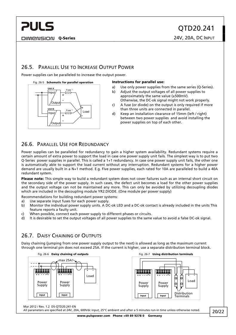
26.5. PARALLEL USE TO INCREASE OUTPUT POWER Power supplies can be paralleled to increase the output power.
Fig. 26-5 Schematic for parallel operation Instructions for parallel use:
Unit B
-+
Load+
-
Fuse *)
Fuse *)
-+
Unit A
Input
Output
Input
Output
a) Use only power supplies from the same series (Q-Series). b) Adjust the output voltages of all power supplies to
approximately the same value (±500mV). Otherwise, the DC-ok signal might not work properly.
c) A fuse (or diode) on the output is only required if more than three units are connected in parallel.
d) Keep an installation clearance of 15mm (left / right) between two power supplies and avoid installing the power supplies on top of each other.
26.6. PARALLEL USE FOR REDUNDANCY Power supplies can be paralleled for redundancy to gain a higher system availability. Redundant systems require a certain amount of extra power to support the load in case one power supply unit fails. The simplest way is to put two Q-Series power supplies in parallel. This is called a 1+1 redundancy. In case one power supply unit fails, the other one is automatically able to support the load current without any interruption. Redundant systems for a higher power demand are usually built in a N+1 method. E.g. Five power supplies, each rated for 10A are paralleled to build a 40A redundant system.
Please note: This simple way to build a redundant system does not cover failures such as an internal short circuit on the secondary side of the power supply. In such cases, the defect unit becomes a load for the other power supplies and the output voltage can not be maintained any more. This can only be avoided by utilizing decoupling diodes which are included in the decoupling module YR2.DIODE. (One module per power supply)
Recommendations for building redundant power systems: a) Use separate input fuses for each power supply. b) Monitor the individual power supply units. A DC-ok LED and a DC-ok contact is already included in the units This
feature reports a faulty unit. c) When possible, connect each power supply to different phases or circuits. d) It is desirable to set the output voltages of all power supplies to the same value to avoid a false DC-ok signal.
26.7. DAISY CHAINING OF OUTPUTS Daisy chaining (jumping from one power supply output to the next) is allowed as long as the maximum current through one terminal pin does not exceed 25A. If the current is higher, use a separate distribution terminal block.
Fig. 26-6 Daisy chaining of outputs Fig. 26-7 Using distribution terminals
PowerSupply
+ + - -
Input
PowerSupply
+ + - -
Input
Load
+ -
max 25A!
PowerSupply
+ + - -
Input
PowerSupply
+ + - -
Input
Load
+ -
DistributionTerminals
20/22
QTD20.241 Q-Series 24V, 20A, DC INPUT
Mar 2012 / Rev. 1.2 DS-QTD20.241-EN All parameters are specified at 24V, 20A, 600Vdc input, 25°C ambient and after a 5 minutes run-in time unless otherwise noted.
www.pulspower.com Phone +49 89 9278 0 Germany
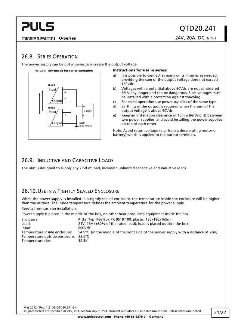
26.8. SERIES OPERATION The power supply can be put in series to increase the output voltage. Fig. 26-8 Schematic for series operation Instructions for use in series:
Unit B
-+
Load+
-
Input
Output
-+
Unit A
Earth(see notes)
Input
Output
a) It is possible to connect as many units in series as needed, providing the sum of the output voltage does not exceed 150Vdc.
b) Voltages with a potential above 60Vdc are not considered SELV any longer and can be dangerous. Such voltages must be installed with a protection against touching.
c) For serial operation use power supplies of the same type. d) Earthing of the output is required when the sum of the
output voltage is above 60Vdc. e) Keep an installation clearance of 15mm (left/right) between
two power supplies and avoid installing the power supplies on top of each other.
Note: Avoid return voltage (e.g. from a decelerating motor or battery) which is applied to the output terminals.
26.9. INDUCTIVE AND CAPACITIVE LOADS The unit is designed to supply any kind of load, including unlimited capacitive and inductive loads.
26.10. USE IN A TIGHTLY SEALED ENCLOSURE When the power supply is installed in a tightly sealed enclosure, the temperature inside the enclosure will be higher than the outside. The inside temperature defines the ambient temperature for the power supply.
Results from such an installation:
Power supply is placed in the middle of the box, no other heat producing equipment inside the box
Enclosure: Rittal Typ IP66 Box PK 9519 100, plastic, 180x180x165mm Load: 24V, 16A (=80% of the rated load); load is placed outside the box Input: 600Vdc Temperature inside enclosure: 54.9°C (in the middle of the right side of the power supply with a distance of 2cm) Temperature outside enclosure: 22.6°C Temperature rise: 32.3K
21/22
QTD20.241 Q-Series 24V, 20A, DC INPUT
Mar 2012 / Rev. 1.2 DS-QTD20.241-EN All parameters are specified at 24V, 20A, 600Vdc input, 25°C ambient and after a 5 minutes run-in time unless otherwise noted.
www.pulspower.com Phone +49 89 9278 0 Germany
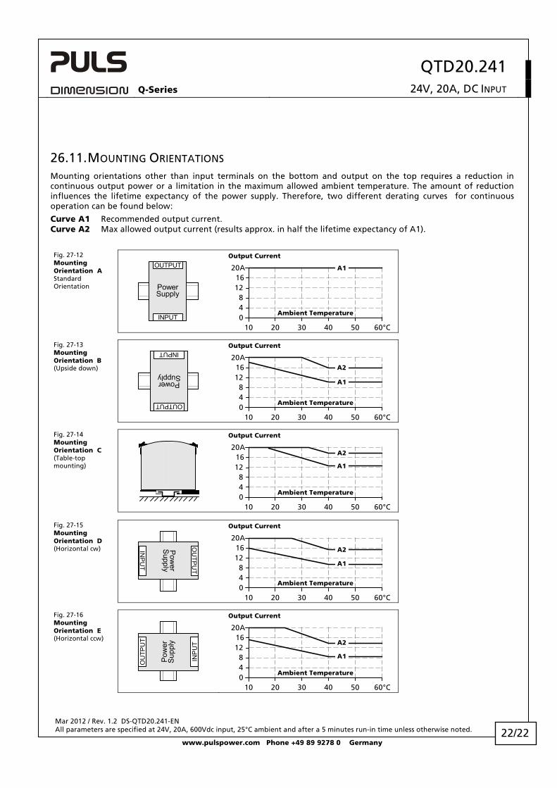
26.11. MOUNTING ORIENTATIONS Mounting orientations other than input terminals on the bottom and output on the top requires a reduction in continuous output power or a limitation in the maximum allowed ambient temperature. The amount of reduction influences the lifetime expectancy of the power supply. Therefore, two different derating curves for continuous operation can be found below:
Curve A1 Recommended output current. Curve A2 Max allowed output current (results approx. in half the lifetime expectancy of A1).
Fig. 27-12 Mounting Orientation A Standard Orientation Power
Supply
OUTPUT
INPUT
Output Current
010 20 30 40 60°C
4
1216
20A
50
A1
8
Ambient Temperature
Fig. 27-13 Mounting Orientation B (Upside down)
PowerSupply
OUTPUT
INPUT
Output Current
010 20 30 40 60°C
4
1216
20A
50
8A1
A2
Ambient Temperature
Fig. 27-14 Mounting Orientation C (Table-top mounting)
Output Current
010 20 30 40 60°C
4
1216
20A
50
8
A1
A2
Ambient Temperature
Fig. 27-15 Mounting Orientation D (Horizontal cw) P
ower
Supply
OU
TPU
T
INP
UT
Output Current
010 20 30 40 60°C
4
1216
20A
50
8A1
A2
Ambient Temperature
Fig. 27-16 Mounting Orientation E (Horizontal ccw)
Pow
erS
uppl
y
OU
TPU
T
INP
UT
Output Current
010 20 30 40 60°C
4
1216
20A
50
8 A1
A2
Ambient Temperature
22/22