bridgwater college electronic ignition - hall effect
TRANSCRIPT

Bridgwater College
Electronic Ignition - Hall Effect
HALL EFFECT IGNITION
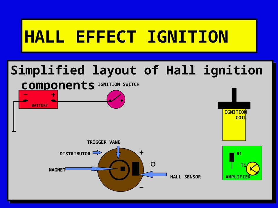
Simplified layout of Hall ignition componentsSimplified layout of Hall ignition components
AMPLIFIER
R1
T1
IGNITION COIL
BATTERY
IGNITION SWITCH
TRIGGER VANE
MAGNET
DISTRIBUTOR
HALL SENSOR

HALL EFFECT IGNITION
Earths to the amplifier and Hall sensorEarths to the amplifier and Hall sensor
AMPLIFIER
R1
T1
IGNITION COIL
BATTERY
IGNITION SWITCH
HALL EFFECT IGNITION
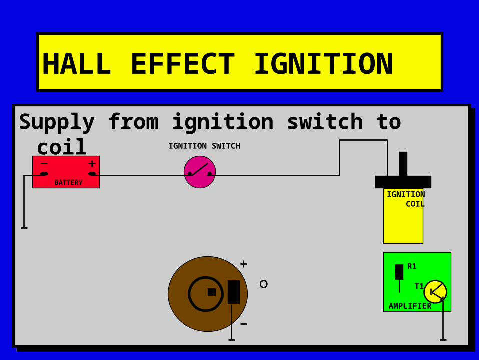
Supply from ignition switch to coilSupply from ignition switch to coil
AMPLIFIER
R1
T1
IGNITION COIL
BATTERY
IGNITION SWITCH
HALL EFFECT IGNITION
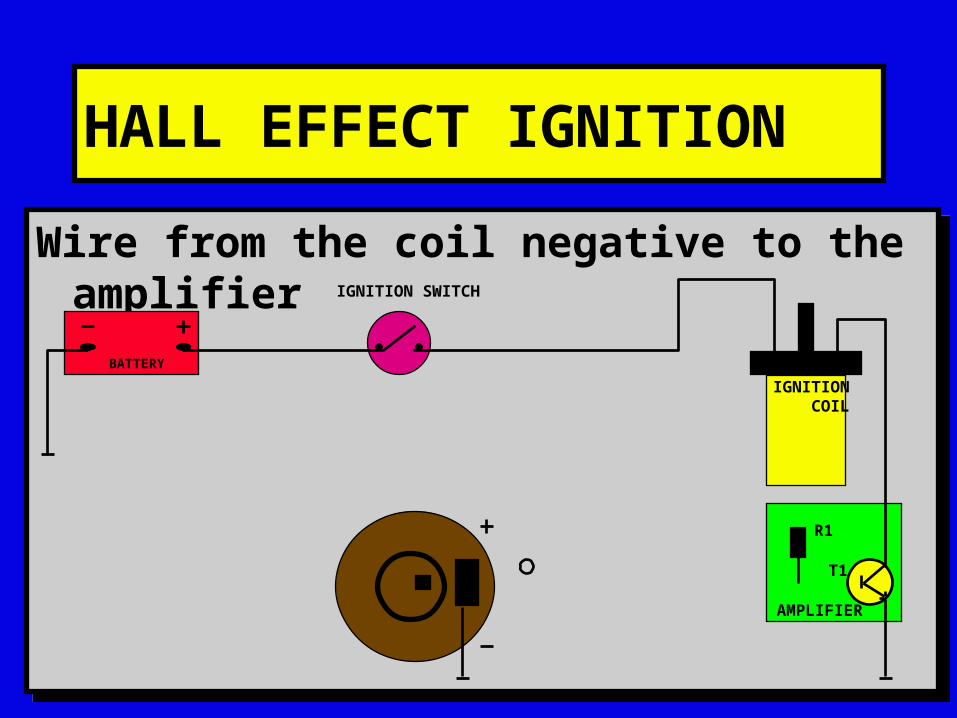
Wire from the coil negative to the amplifierWire from the coil negative to the amplifier
AMPLIFIER
R1
T1
IGNITION COIL
BATTERY
IGNITION SWITCH

HALL EFFECT IGNITION
Live supply from ignition to the amplifierLive supply from ignition to the amplifier
AMPLIFIER
R1
T1
IGNITION COIL
BATTERY
IGNITION SWITCH
HALL EFFECT IGNITION
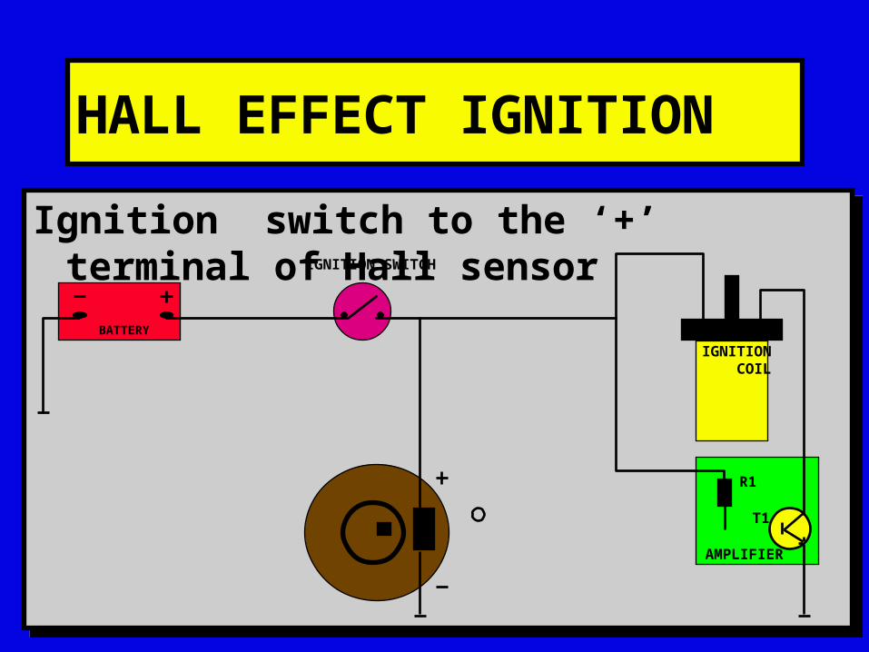
Ignition switch to the ‘+’ terminal of Hall sensorIgnition switch to the ‘+’ terminal of Hall sensor
AMPLIFIER
R1
T1
IGNITION COIL
BATTERY
IGNITION SWITCH
HALL EFFECT IGNITION
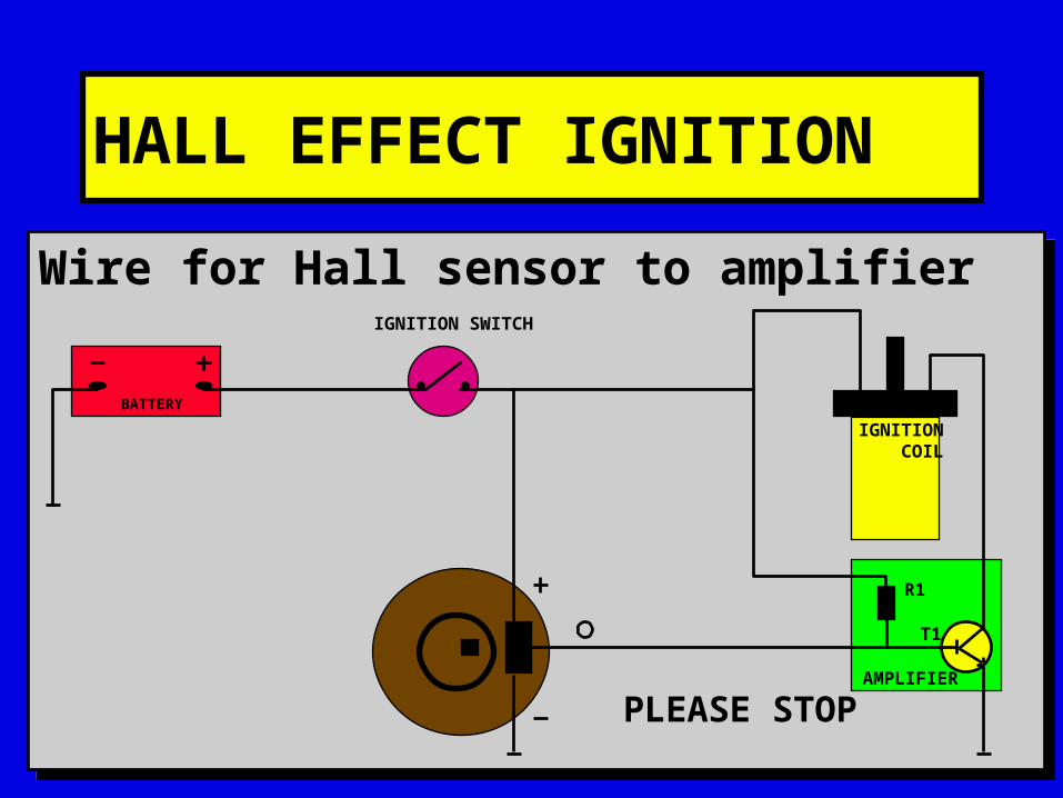
Wire for Hall sensor to amplifierWire for Hall sensor to amplifier
AMPLIFIER
R1
T1
IGNITION COIL
BATTERY
IGNITION SWITCH
PLEASE STOP
HALL EFFECT IGNITION
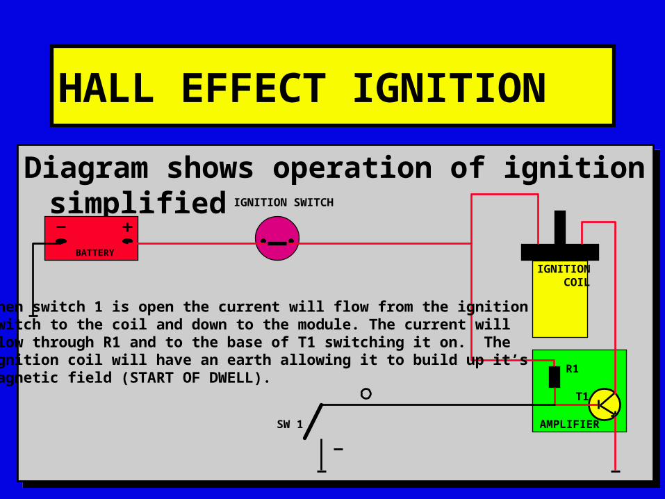
Diagram shows operation of ignition simplifiedDiagram shows operation of ignition simplified
AMPLIFIER
R1
T1
IGNITION COIL
BATTERY
IGNITION SWITCH
SW 1
When switch 1 is open the current will flow from the ignitionswitch to the coil and down to the module. The current willflow through R1 and to the base of T1 switching it on. Theignition coil will have an earth allowing it to build up it’smagnetic field (START OF DWELL).
HALL EFFECT IGNITION
AMPLIFIER
R1
T1
IGNITION COIL
BATTERY
IGNITION SWITCH
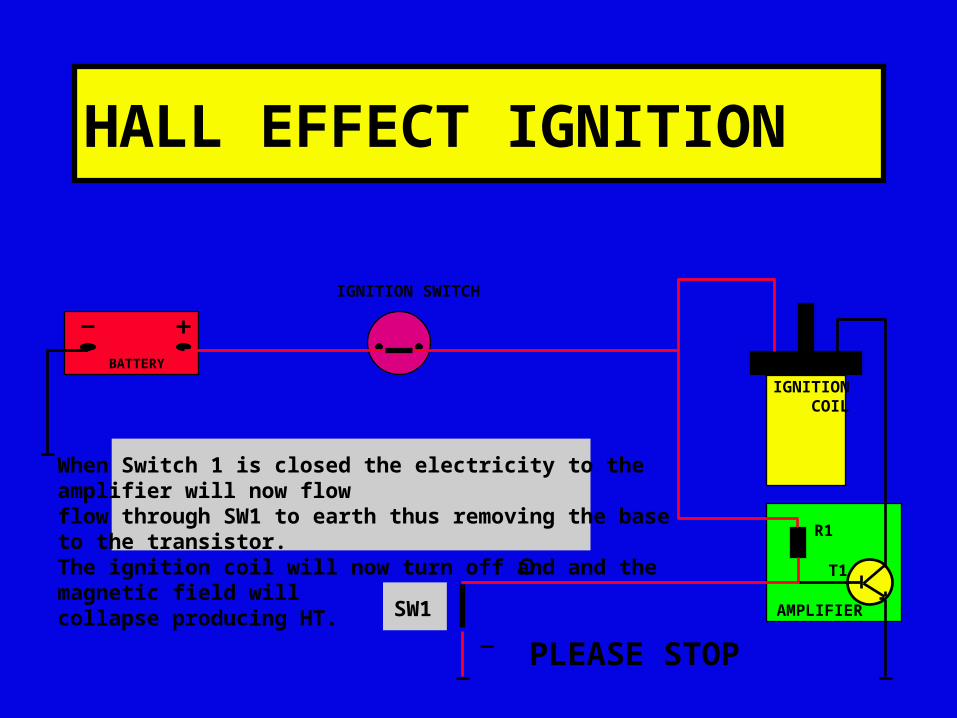
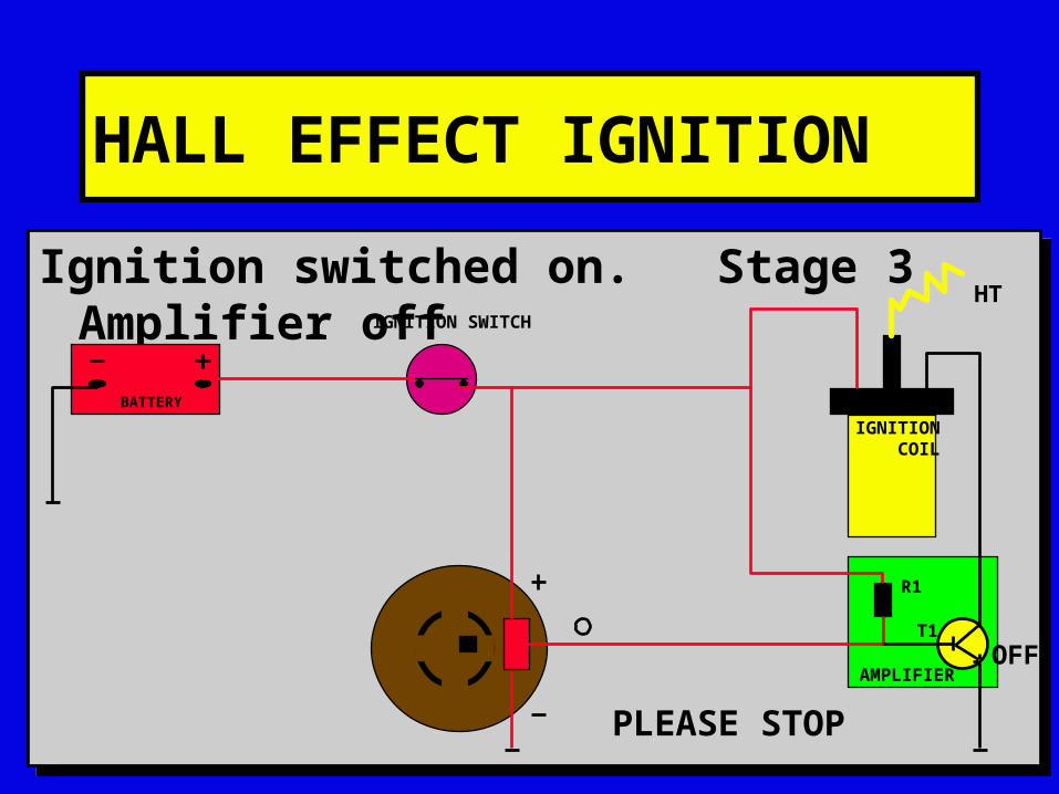
When Switch 1 is closed the electricity to the amplifier will now flowflow through SW1 to earth thus removing the base to the transistor.The ignition coil will now turn off and and the magnetic field willcollapse producing HT.
SW1
PLEASE STOP
HALL EFFECT IGNITION
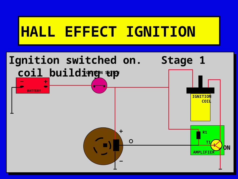
Ignition switched on. Stage 1 coil building upIgnition switched on. Stage 1 coil building up
AMPLIFIER
R1
T1
IGNITION COIL
BATTERY
IGNITION SWITCH
ON
HALL EFFECT IGNITION
Ignition switched on. Stage 3 Amplifier offIgnition switched on. Stage 3 Amplifier off
AMPLIFIER
R1
T1
IGNITION COIL
BATTERY
IGNITION SWITCH
HT
PLEASE STOP
OFF
HALL EFFECT IGNITION
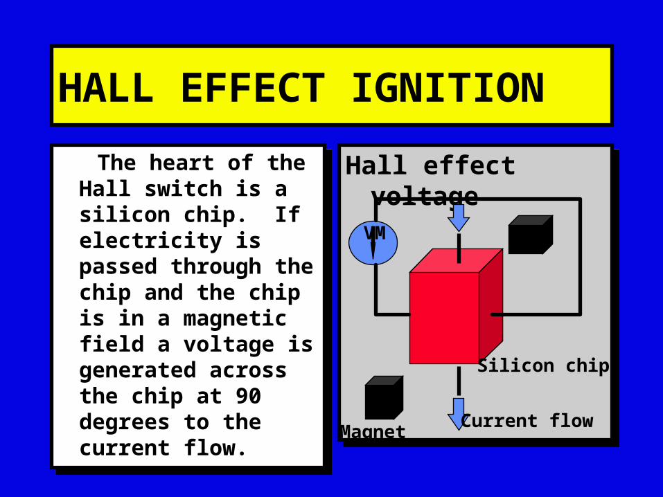
The heart of the Hall switch is a silicon chip. If electricity is passed through the chip and the chip is in a magnetic field a voltage is generated across the chip at 90 degrees to the current flow.
The heart of the Hall switch is a silicon chip. If electricity is passed through the chip and the chip is in a magnetic field a voltage is generated across the chip at 90 degrees to the current flow.
Hall effect voltageHall effect voltage
Silicon chip
Current flowMagnet
VM
HALL EFFECT IGNITION
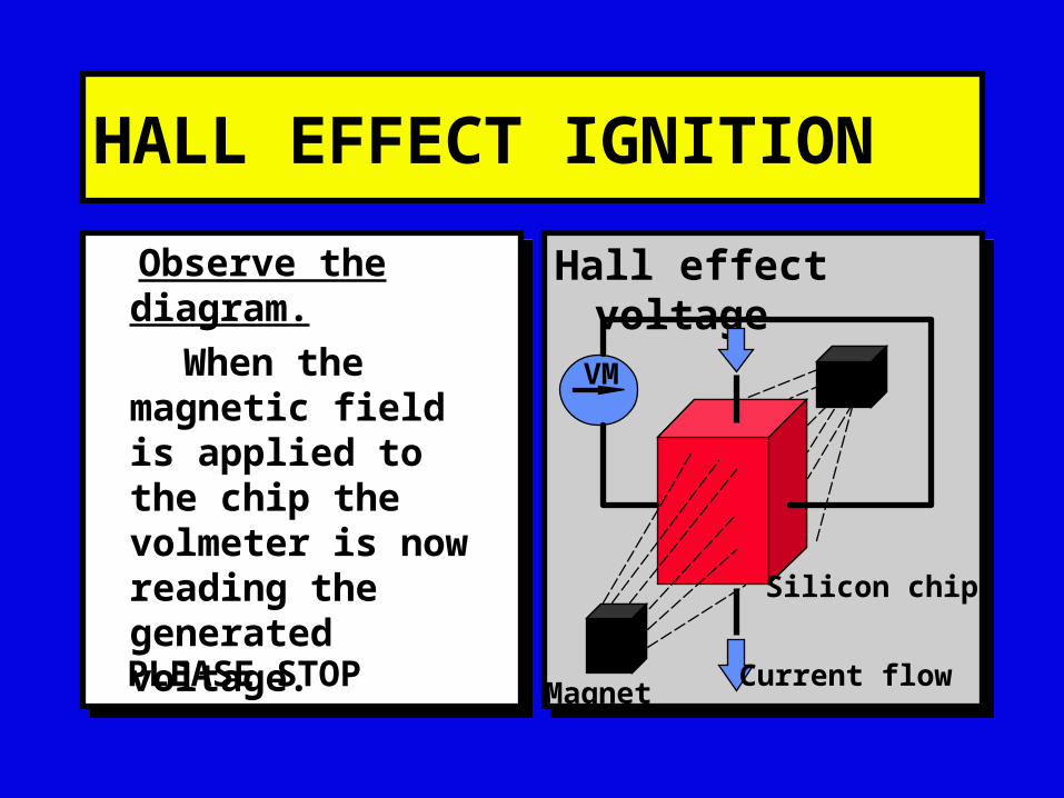
Observe the diagram.
When the magnetic field is applied to the chip the volmeter is now reading the generated voltage.
Observe the diagram.
When the magnetic field is applied to the chip the volmeter is now reading the generated voltage.
Hall effect voltageHall effect voltage
Silicon chip
Current flowMagnet
VM
PLEASE STOP
HALL EFFECT IGNITION
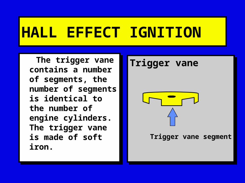
The trigger vane contains a number of segments, the number of segments is identical to the number of engine cylinders. The trigger vane is made of soft iron.
The trigger vane contains a number of segments, the number of segments is identical to the number of engine cylinders. The trigger vane is made of soft iron.
Trigger vaneTrigger vane
Trigger vane segment
HALL EFFECT IGNITION
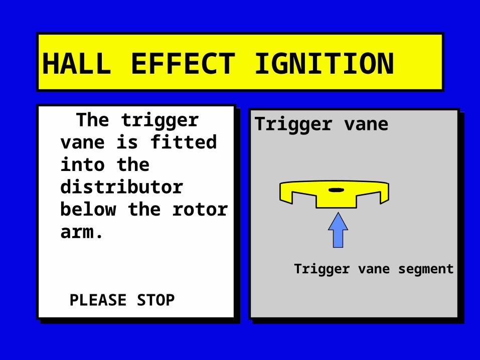
The trigger vane is fitted into the distributor below the rotor arm.
The trigger vane is fitted into the distributor below the rotor arm.
Trigger vaneTrigger vane
Trigger vane segment
PLEASE STOP
HALL EFFECT IGNITION
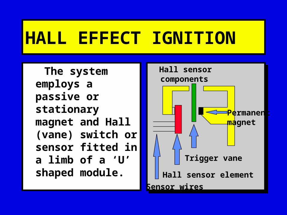
The system employs a passive or stationary magnet and Hall (vane) switch or sensor fitted in a limb of a ‘U’ shaped module.
Hall sensor components Hall sensor components
Trigger vane
Permanentmagnet
Hall sensor element
Sensor wires
HALL EFFECT IGNITION
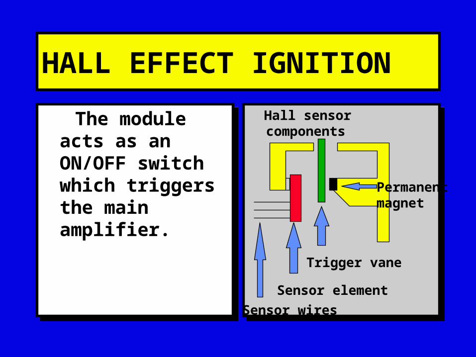
The module acts as an ON/OFF switch which triggers the main amplifier.
The module acts as an ON/OFF switch which triggers the main amplifier.
Hall sensor components Hall sensor components
Trigger vane
Permanentmagnet
Sensor element
Sensor wires
HALL EFFECT IGNITION
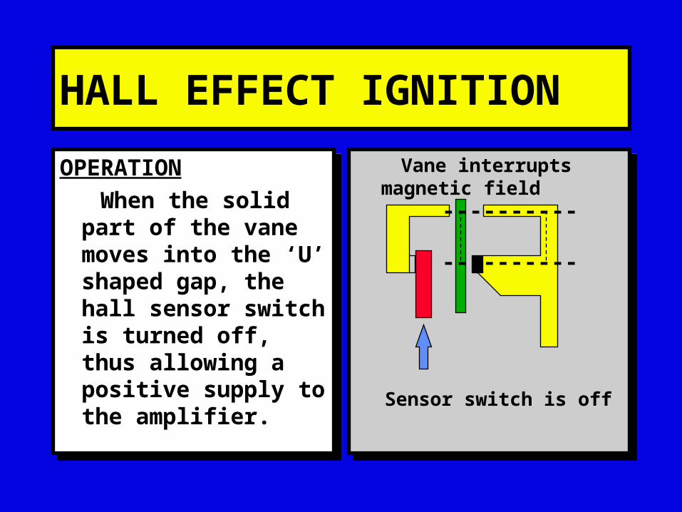
OPERATION
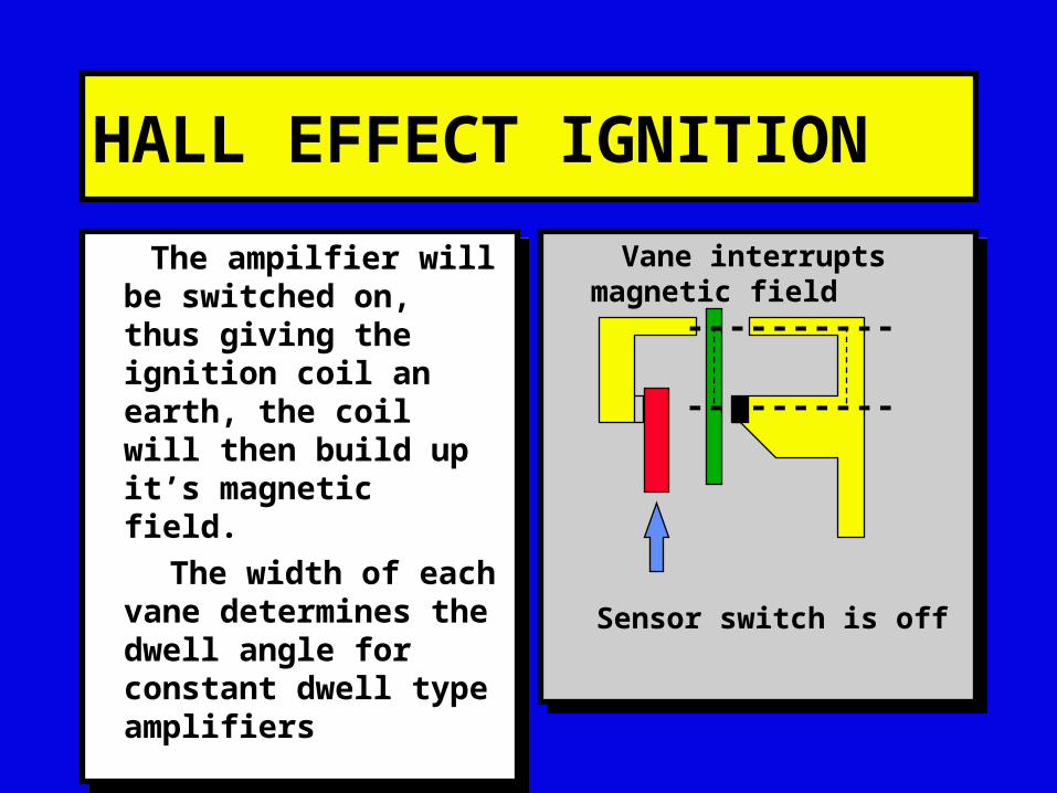
When the solid part of the vane moves into the ‘U’ shaped gap, the hall sensor switch is turned off, thus allowing a positive supply to the amplifier.
OPERATION
When the solid part of the vane moves into the ‘U’ shaped gap, the hall sensor switch is turned off, thus allowing a positive supply to the amplifier.
Vane interrupts magnetic field
Vane interrupts magnetic field
----------
----------
Sensor switch is off
HALL EFFECT IGNITION
The ampilfier will be switched on, thus giving the ignition coil an earth, the coil will then build up it’s magnetic field.
The width of each vane determines the dwell angle for constant dwell type amplifiers
The ampilfier will be switched on, thus giving the ignition coil an earth, the coil will then build up it’s magnetic field.
The width of each vane determines the dwell angle for constant dwell type amplifiers
Vane interrupts magnetic field
Vane interrupts magnetic field
----------
----------
Sensor switch is off
HALL EFFECT IGNITION
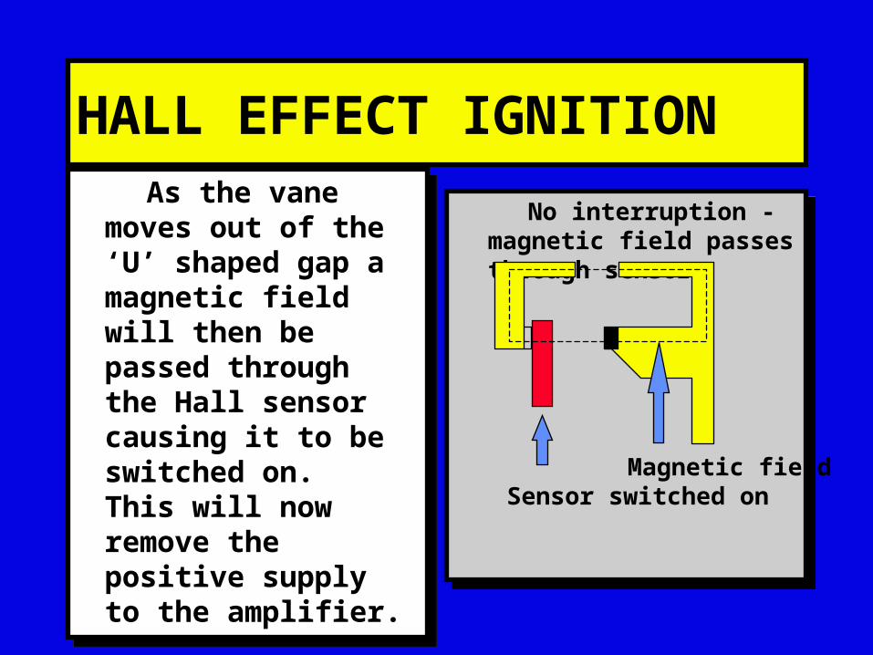
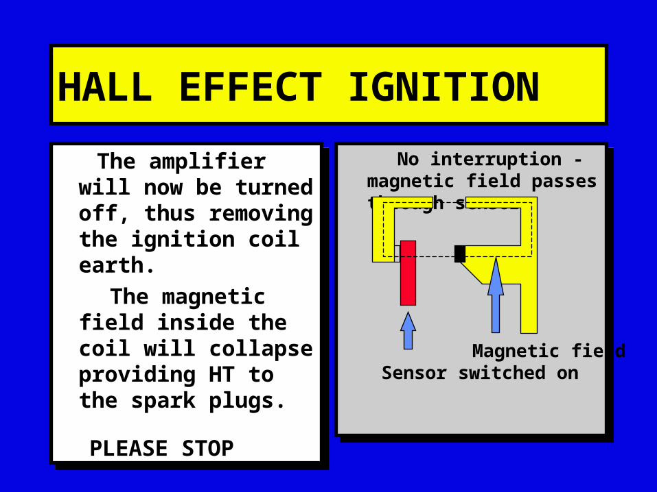
No interruption - magnetic field passes through sensor
No interruption - magnetic field passes through sensor
Sensor switched onMagnetic field
As the vane moves out of the ‘U’ shaped gap a magnetic field will then be passed through the Hall sensor causing it to be switched on. This will now remove the positive supply to the amplifier.
As the vane moves out of the ‘U’ shaped gap a magnetic field will then be passed through the Hall sensor causing it to be switched on. This will now remove the positive supply to the amplifier.
HALL EFFECT IGNITION
No interruption - magnetic field passes through sensor
No interruption - magnetic field passes through sensor
Sensor switched onMagnetic field
The amplifier will now be turned off, thus removing the ignition coil earth.
The magnetic field inside the coil will collapse providing HT to the spark plugs.
The amplifier will now be turned off, thus removing the ignition coil earth.
The magnetic field inside the coil will collapse providing HT to the spark plugs.PLEASE STOP

HALL EFFECT IGNITION
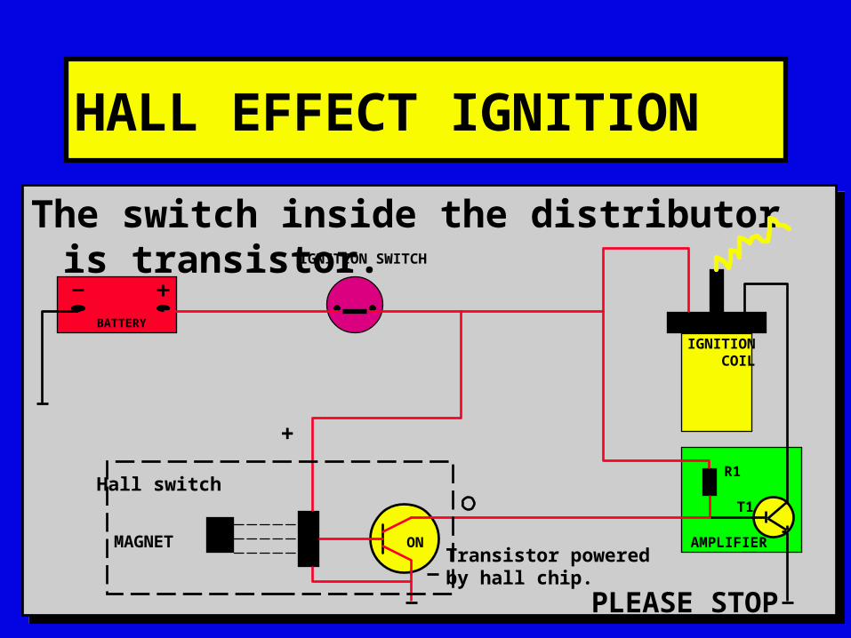
The switch inside the distributor is transistor.The switch inside the distributor is transistor.
AMPLIFIER
R1
T1
IGNITION COIL
BATTERY
IGNITION SWITCH
+
Hall switch
Transistor poweredby hall chip.
OFFMAGNET
VANE PLEASE STOP
HALL EFFECT IGNITION
The switch inside the distributor is transistor.The switch inside the distributor is transistor.
AMPLIFIER
R1
T1
IGNITION COIL
BATTERY
IGNITION SWITCH
+
Hall switch
Transistor poweredby hall chip.
ONMAGNET
PLEASE STOP

HALL EFFECT IGNITION
SYSTEM COMPONENTS
7 6 5 4 3 2 1
+0
15 1
AMPLIFIER
COIL
BATTERYING SW
DISTRIBUTOR

HALL EFFECT IGNITION
LIVE SUPPLY TO AMPLIFIER AND COIL
7 6 5 4 3 2 1
+0
15 1
AMPLIFIER
COIL
BATTERYING SW
DISTRIBUTOR

HALL EFFECT IGNITION
EARTH WIRE TO AMPLIFIER
7 6 5 4 3 2 1
+0
15 1
AMPLIFIER
COIL
BATTERYING SW
DISTRIBUTOR
HALL EFFECT IGNITION
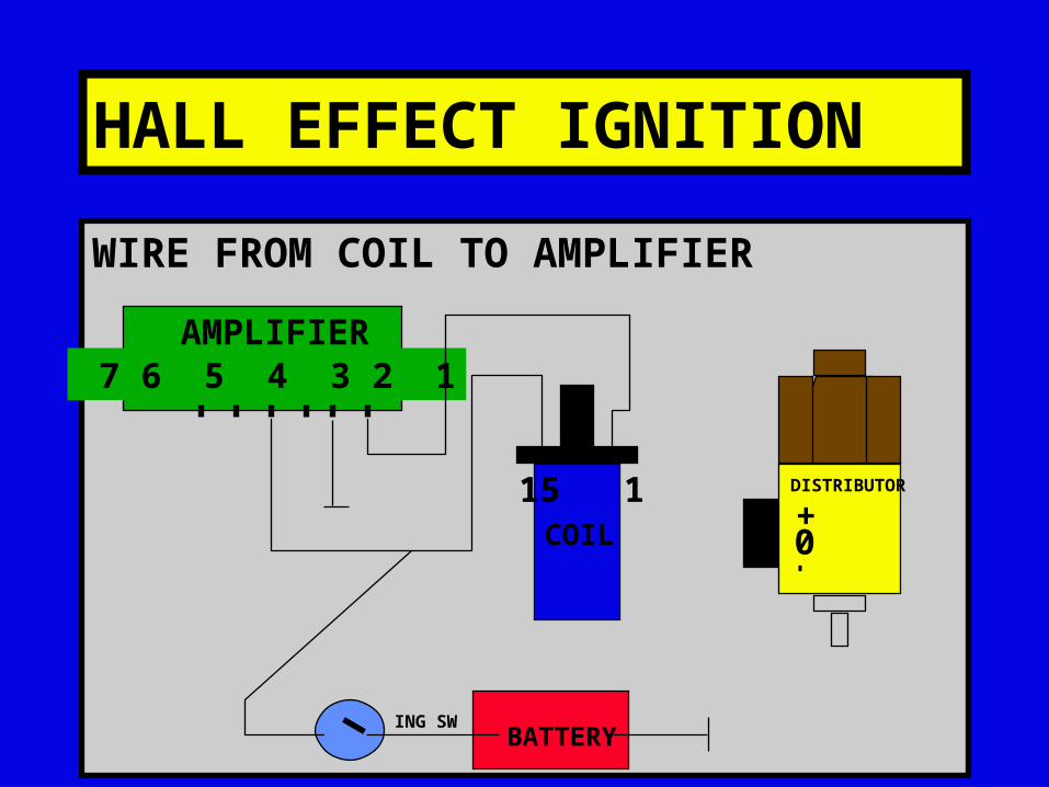
WIRE FROM COIL TO AMPLIFIER
7 6 5 4 3 2 1
+0
15 1
AMPLIFIER
COIL
BATTERYING SW
DISTRIBUTOR

HALL EFFECT IGNITION
WIRE FROM AMPLIFIER TO ‘+’ ON ‘DIST’
7 6 5 4 3 2 1
+0
15 1
AMPLIFIER
COIL
BATTERYING SW
DISTRIBUTOR

HALL EFFECT IGNITION
WIRE FROM AMPLIFIER TO ‘-’ ON ‘DIST’
7 6 5 4 3 2 1
+0
15 1
AMPLIFIER
COIL
BATTERYING SW
DISTRIBUTOR

HALL EFFECT IGNITION
WIRE FROM AMPLIFIER TO ‘0’ ON ‘DIST’
7 6 5 4 3 2 1
+0
15 1
AMPLIFIER
COIL
BATTERYING SW
DISTRIBUTOR
HALL EFFECT IGNITION
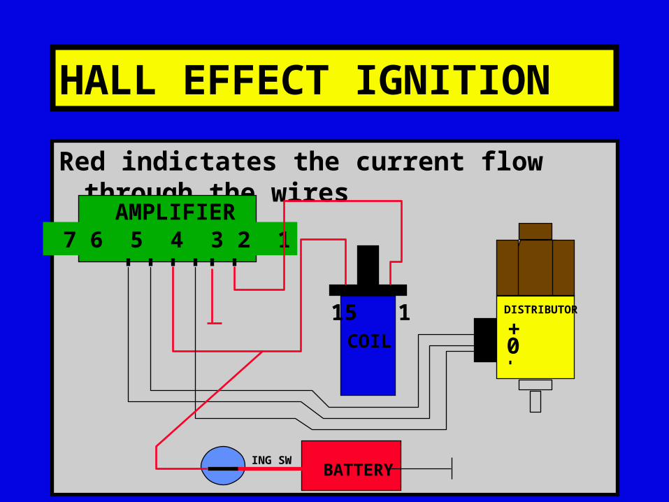
Red indictates the current flow through the wires
7 6 5 4 3 2 1
+0
15 1
AMPLIFIER
COIL
BATTERYING SW
DISTRIBUTOR
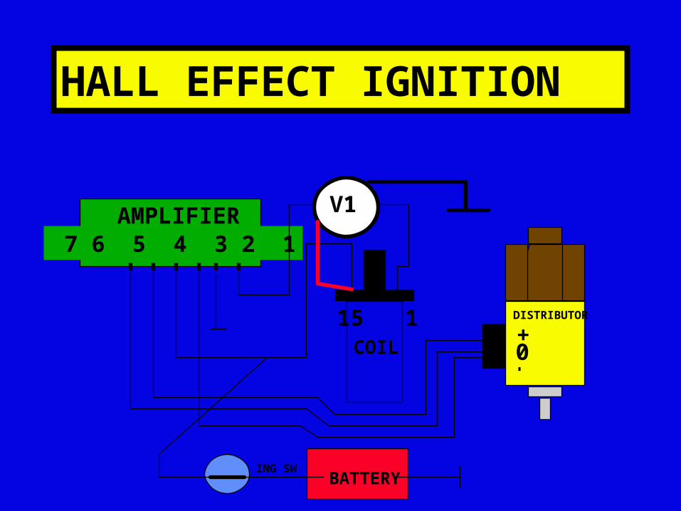
HALL EFFECT IGNITION
7 6 5 4 3 2 1
+0
15 1
AMPLIFIER
COIL
BATTERYING SW
DISTRIBUTOR
V1
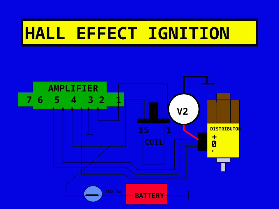
HALL EFFECT IGNITION
7 6 5 4 3 2 1
+0
15 1
AMPLIFIER
COIL
BATTERYING SW
DISTRIBUTOR
V2
HALL EFFECT IGNITION
7 6 5 4 3 2 1
+0
15 1
AMPLIFIER
COIL
BATTERYING SW
DISTRIBUTOR
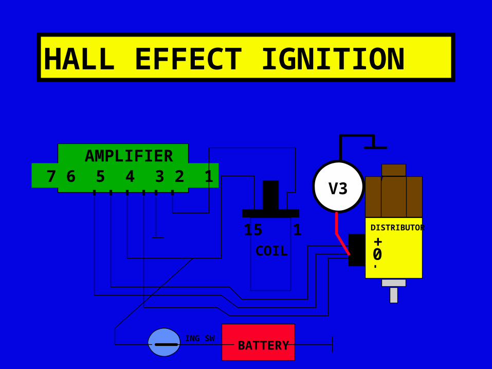
V3
HALL EFFECT IGNITION
7 6 5 4 3 2 1
+0
15 1
AMPLIFIER
COIL
BATTERYING SW
DISTRIBUTOR
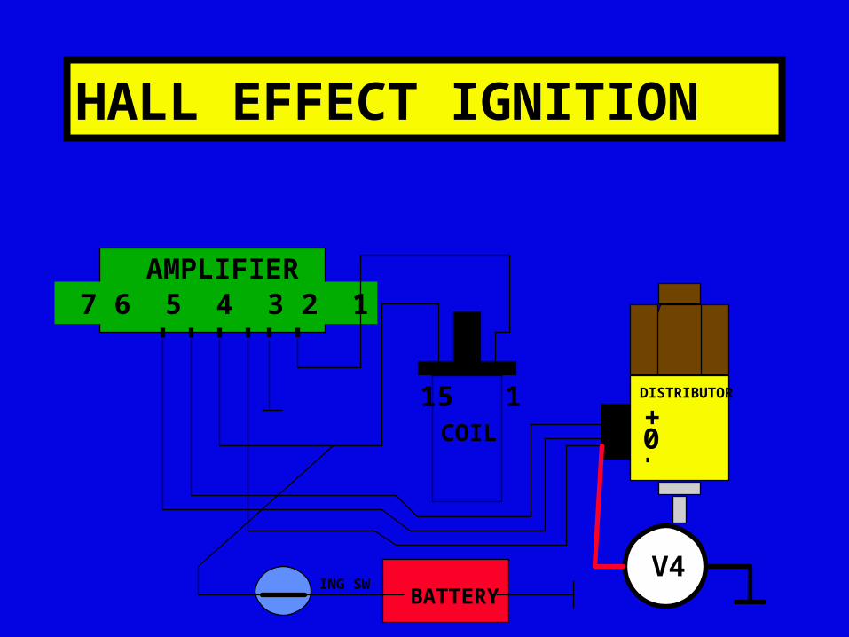
V4
HALL EFFECT IGNITION
7 6 5 4 3 2 1
+0
15 1
AMPLIFIER
COIL
BATTERYING SW
DISTRIBUTOR
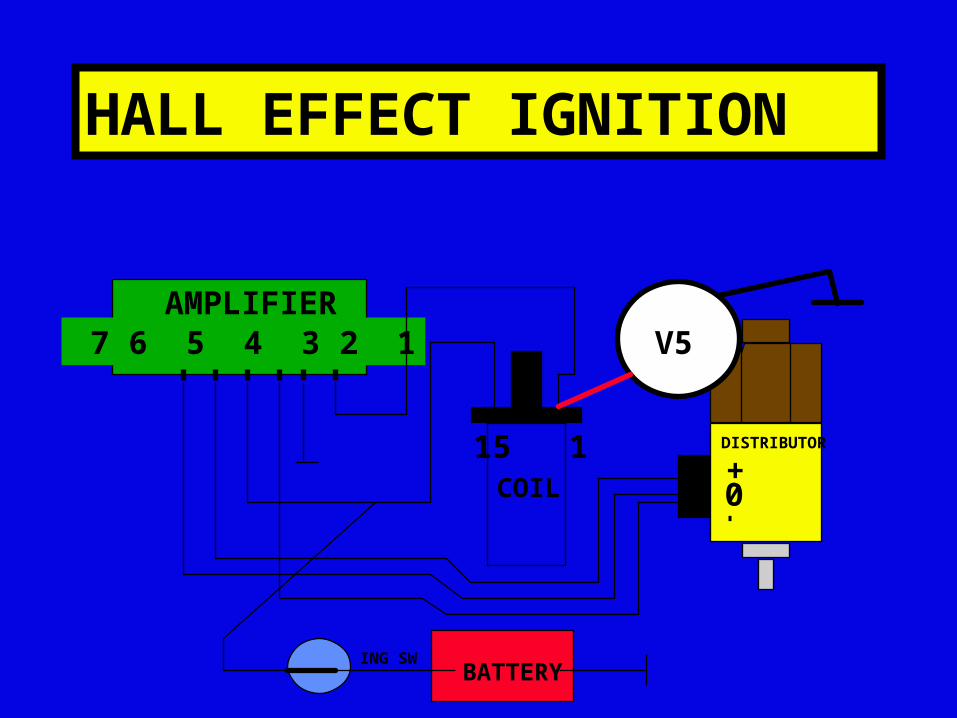
V5

HALL EFFECT IGNITION
7 6 5 4 3 2 1
+0
15 1
AMPLIFIER
COIL
BATTERYING SW
DISTRIBUTOR
V6

HALL EFFECT IGNITION
7 6 5 4 3 2 1
+0
15 1
AMPLIFIER
COIL
BATTERYING SW
DISTRIBUTOR
V7

HALL EFFECT IGNITION
7 6 5 4 3 2 1
+0
15 1
AMPLIFIER
COIL
BATTERYING SW
DISTRIBUTOR
V8

HALL EFFECT IGNITION
7 6 5 4 3 2 1
+0
15 1
AMPLIFIER
COIL
BATTERYING SW
DISTRIBUTOR
V9
HALL EFFECT IGNITION
7 6 5 4 3 2 1
+0
15 1
AMPLIFIER
COIL
BATTERYING SW
DISTRIBUTOR
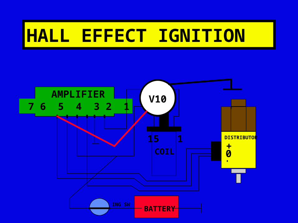
V10
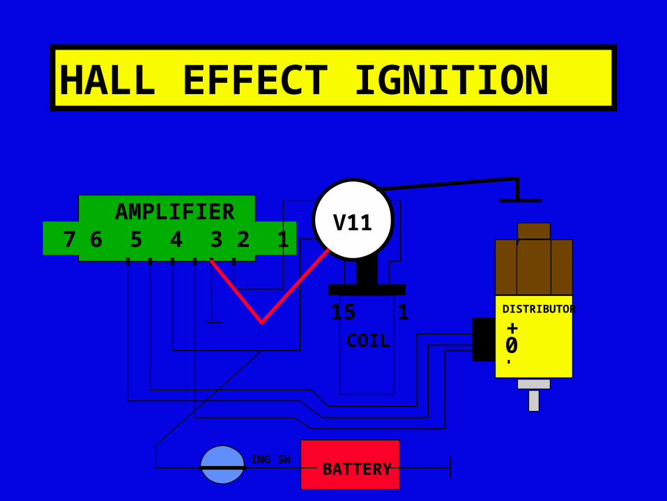
HALL EFFECT IGNITION
7 6 5 4 3 2 1
+0
15 1
AMPLIFIER
COIL
BATTERYING SW
DISTRIBUTOR
V11