pjm planning modeling data requirements and reporting
TRANSCRIPT
www.pjm.com | For Public Use PJM Planning Modeling Data Requirements and Reporting Procedures
1 | P a g e
PJM Planning Modeling Data Requirements and Reporting Procedures for Steady State Power Flow, Dynamics, and Short Circuit PJM System Planning Division System Planning Modeling and Support Department April 1, 2021

www.pjm.com | For Public Use PJM Planning Modeling Data Requirements and Reporting Procedures
2 | P a g e
Table of Contents 1. Introduction..................................................................................................................................... 4
1.1. Purpose.................................................................................................................................... 4
1.2. Background .............................................................................................................................. 4
1.3. Process Overview ..................................................................................................................... 4
1.4. Data Requirements and Reporting Procedures ......................................................................... 6
1.4.1. Data Checks ...................................................................................................................... 6
1.5. Responsible Entities and Expectations ...................................................................................... 6
2. PJM Deliverables.............................................................................................................................. 7
2.1. Load Flow................................................................................................................................. 7
2.2. Dynamics ................................................................................................................................. 8
2.3. Short Circuit ............................................................................................................................. 8
2.4. Document Organization ........................................................................................................... 9
3. Generator Owners ......................................................................................................................... 10
3.1. Schedule ................................................................................................................................ 10
3.1.1. As-Built Submittals (required for post-interconnection for new generators or increased generator capability)...................................................................................................................... 10
3.1.2. Annual Gen Model Window Submittals .......................................................................... 10
3.2. Applicability ........................................................................................................................... 11
3.3. Power Flow ............................................................................................................................ 11
3.4. Dynamics ............................................................................................................................... 11
3.4.1. Modeling Level of Detail ................................................................................................. 12
3.4.2. Accepted Dynamics Models ............................................................................................ 12
3.4.3. Dynamics Data Checks, Initialization, and Acceptance..................................................... 12
3.5. Short Circuit ........................................................................................................................... 12
4. Transmission Owners ..................................................................................................................... 13
4.1. Power Flow Cases................................................................................................................... 14
4.1.1. Schedule......................................................................................................................... 14
4.1.2. Format ........................................................................................................................... 14
4.1.3. Level of Detail ................................................................................................................. 15
4.1.4. Power Flow via Model On Demand ................................................................................. 16
www.pjm.com | For Public Use PJM Planning Modeling Data Requirements and Reporting Procedures
3 | P a g e
4.1.5. Tie-Lines ......................................................................................................................... 16
4.1.6. Interchange .................................................................................................................... 17
4.2. Dynamics ............................................................................................................................... 17
4.2.1. Dynamics Schedule ......................................................................................................... 17
4.2.2. Format ........................................................................................................................... 17
4.2.3. Dynamic Load Model Data .............................................................................................. 18
4.2.4. Accepted Dynamics Models ............................................................................................ 18
4.2.5. Dynamics Data Checks, Initialization, and Acceptance..................................................... 18
4.3. Short Circuit ........................................................................................................................... 18
4.3.1. Schedule......................................................................................................................... 18
4.3.2. Format ........................................................................................................................... 19
4.3.3. Short Circuit Level of Detail............................................................................................. 19
4.3.4. Short Circuit Submittal Procedure ................................................................................... 20
5. Appendix 1: Generator Owner Data Requirements ........................................................................ 21
6. Appendix 2: Transmission Owner Data Requirements ..................................................................... 22
6.1. Power Flow Data .................................................................................................................... 22
6.2. Short Circuit Data ................................................................................................................... 24
7. Appendix 3: BES and Non-BES Demarcation Guidance for MoD ..................................................... 27
7.1. Criteria for PJM TO Entities to Submit Data into Siemens Model On Demand (MoD) .............. 27
7.2. Additional Modeling Considerations ....................................................................................... 27
7.3. Accepting Changes from PJM Non-Incumbent TOs ................................................................. 28
7.4. Modeling Responsibilities for Existing Facilities Examples ....................................................... 28
7.5. Modeling Responsibilities for Approved Network Upgrade Projects Examples ........................ 32
8. Appendix 4: Document Revision History......................................................................................... 36
www.pjm.com | For Public Use PJM Planning Modeling Data Requirements and Reporting Procedures
4 | P a g e
1. Introduction
1.1. Purpose PJM created this document to collect the necessary data from its wholesale market participants to develop reliable and accurate data for modeling and reliability analyses. PJM’s data collection process is meets or exceeds NERC modeling requirements specified in the MOD-032 standard. MOD-032, according to the NERC standard, is to “establish consistent modeling data requirements and reporting procedures for development of planning horizon cases necessary to support analysis of the reliability of the interconnected transmission system”. The purpose of this document is to establish the data requirements, schedules, and submission methods to ensure data owner compliance with the standard.
1.2. Background The MOD-032 and MOD-033 standards are focused on system-level modeling and validation. MOD-032 replaces and consolidates MOD-010-0, MOD-011-0, MOD-012-0, MOD-013-0, MOD-014-0, and MOD-015-0.1. It requires various Functional Entities, as data owners, to submit data to their Transmission Planner(s) (TP) and Planning Coordinator(s) (PC). These data owners include Transmission Owners (TO), and Generation Owners (GO). The data submitted is used to inform the steady state, dynamics, and short circuit models for various years and scenarios. MOD-033 is a new standard requiring every PC to put into place a process to validate the models for its area. Thus, MOD-032 ensures owners of equipment submit quality data input to system-level models and MOD-033 validates that data through comparisons to actual data and system event response. PJM developed data and modeling requirements for generators 20 MW or greater participating meet or exceed MOD-032 requirements for its applicable participants. On July 1, 2015, requirement 1 (R1) became effective and required PJM to develop data requirements and reporting procedures to collect the necessary data in the remaining requirements of MOD-032, which became effective on July 1, 2016. It should be noted that FERC approved removal of Load-Serving Entity (LSE) as a functional registration category on October 15, 2015. Therefore, even though LSEs are still referred to in the standard they are no longer applicable.
1.3. Process Overview PJM is the TP and PC for its region and therefore must develop data requirements, reporting procedures, and schedules for the data owners in its area to provide data to build steady state, dynamics, and short circuit cases. MOD-032 Requirement 1.2.4 states that the data must be submitted at least every 13 months.
www.pjm.com | For Public Use PJM Planning Modeling Data Requirements and Reporting Procedures
5 | P a g e
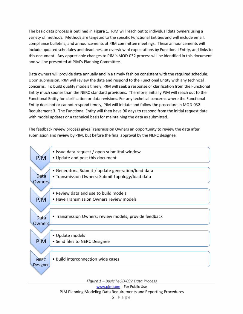
The basic data process is outlined in Figure 1. PJM will reach out to individual data owners using a variety of methods. Methods are targeted to the specific Functional Entities and will include email, compliance bulletins, and announcements at PJM committee meetings. These announcements will include updated schedules and deadlines, an overview of expectations by Functional Entity, and links to this document. Any appreciable changes to PJM’s MOD-032 process will be identified in this document and will be presented at PJM’s Planning Committee. Data owners will provide data annually and in a timely fashion consistent with the required schedule. Upon submission, PJM will review the data and respond to the Functional Entity with any technical concerns. To build quality models timely, PJM will seek a response or clarification from the Functional Entity much sooner than the NERC standard provisions. Therefore, initially PJM will reach out to the Functional Entity for clarification or data revisions. For any technical concerns where the Functional Entity does not or cannot respond timely, PJM will initiate and follow the procedure in MOD-032 Requirement 3. The Functional Entity will then have 90 days to respond from the initial request date with model updates or a technical basis for maintaining the data as submitted. The feedback review process gives Transmission Owners an opportunity to review the data after submission and review by PJM, but before the final approval by the NERC designee.
Figure 1 – Basic MOD-032 Data Process
PJM• Issue data request / open submittal window• Update and post this document
Data Owners
• Generators: Submit / update generation/load data• Transmission Owners: Submit topology/load data
PJM• Review data and use to build models• Have Transmission Owners review models
Data Owners
• Transmission Owners: review models, provide feedback
PJM• Update models• Send files to NERC Designee
NERC Designee
• Build interconnection wide cases
www.pjm.com | For Public Use PJM Planning Modeling Data Requirements and Reporting Procedures
6 | P a g e
1.4. Data Requirements and Reporting Procedures This document is posted on the MOD-032 webpage on PJM.com located below: https://pjm.com/planning/services-requests/planning-modeling-submission-mod-032.aspx The information in this document and the data requirements and reporting procedures were developed by PJM staff to ensure PJM’s compliance with MOD-032 requirement 1. PJM incorporated feedback into this document provided from representatives from various functional entities including GOs and TOs. Each year, PJM communicates any updates to its MOD-032 process via this document, emails through various committee mailing lists, and/or with in-person announcements at PJM committees, such as the Planning Committee. PJM expects all applicable parties to be attentive to communications, committee activities and pjm.com for MOD-032 compliance announcements. It is expected that applicable parties will review this document annually. The version of this document posted on pjm.com is the latest version. In addition, PJM will reach out directly to TOs and GOs with its current modeling contacts list. In addition, PJM’s compliance bulletin will be updated if MOD-032 is modified by NERC.
1.4.1. Data Checks The MMWG has established a set of Power Flow Data Checks, defined in their manual. PJM will run the MMWG’s data checking program to identify all errors according to the criteria defined by MMWG. All finalized power flow models shall be free of all such errors, or expectations shall be documented as required by MMWG procedure. The latest MMWG manual can be found at MMWG’s website located here: https://rfirst.org/ProgramAreas/ESP/ERAG/MMWG/ERAG%20%20MMWG%20Library/MMWG_Procedural_Manual_V27.pdf#search=MMWG%20Manual
1.5. Responsible Entities and Expectations Similar to NERC, PJM requires generating facilities with cumulative generation of 20 MW or more to submit the data to PJM annually. For facilities that meet NERC reporting requirements, Requirement 2 of MOD-032 requires GOs and TOs to submit steady state, dynamics, and short circuit data to their TPs and PCs according to the requirements, schedules, and submission methods as set out in this document. As mentioned in Section 1.2, even though LSEs are still referred to in the standard, they are no longer applicable.
www.pjm.com | For Public Use PJM Planning Modeling Data Requirements and Reporting Procedures
7 | P a g e
2. PJM Deliverables
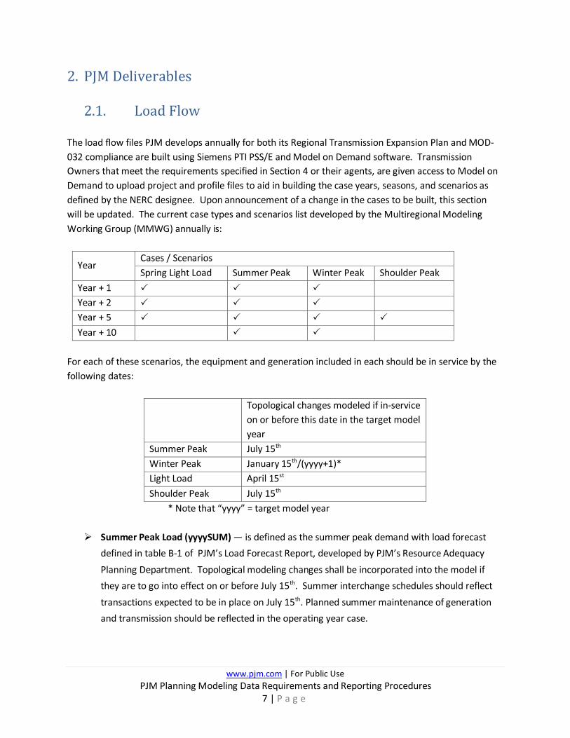
2.1. Load Flow The load flow files PJM develops annually for both its Regional Transmission Expansion Plan and MOD-032 compliance are built using Siemens PTI PSS/E and Model on Demand software. Transmission Owners that meet the requirements specified in Section 4 or their agents, are given access to Model on Demand to upload project and profile files to aid in building the case years, seasons, and scenarios as defined by the NERC designee. Upon announcement of a change in the cases to be built, this section will be updated. The current case types and scenarios list developed by the Multiregional Modeling Working Group (MMWG) annually is:
Year Cases / Scenarios Spring Light Load Summer Peak Winter Peak Shoulder Peak
Year + 1 Year + 2 Year + 5 Year + 10
For each of these scenarios, the equipment and generation included in each should be in service by the following dates:
Topological changes modeled if in-service on or before this date in the target model year
Summer Peak July 15th Winter Peak January 15th/(yyyy+1)* Light Load April 15st Shoulder Peak July 15th
* Note that “yyyy” = target model year Summer Peak Load (yyyySUM) — is defined as the summer peak demand with load forecast
defined in table B-1 of PJM’s Load Forecast Report, developed by PJM’s Resource Adequacy
Planning Department. Topological modeling changes shall be incorporated into the model if they are to go into effect on or before July 15th. Summer interchange schedules should reflect
transactions expected to be in place on July 15th. Planned summer maintenance of generation and transmission should be reflected in the operating year case.
www.pjm.com | For Public Use PJM Planning Modeling Data Requirements and Reporting Procedures
8 | P a g e
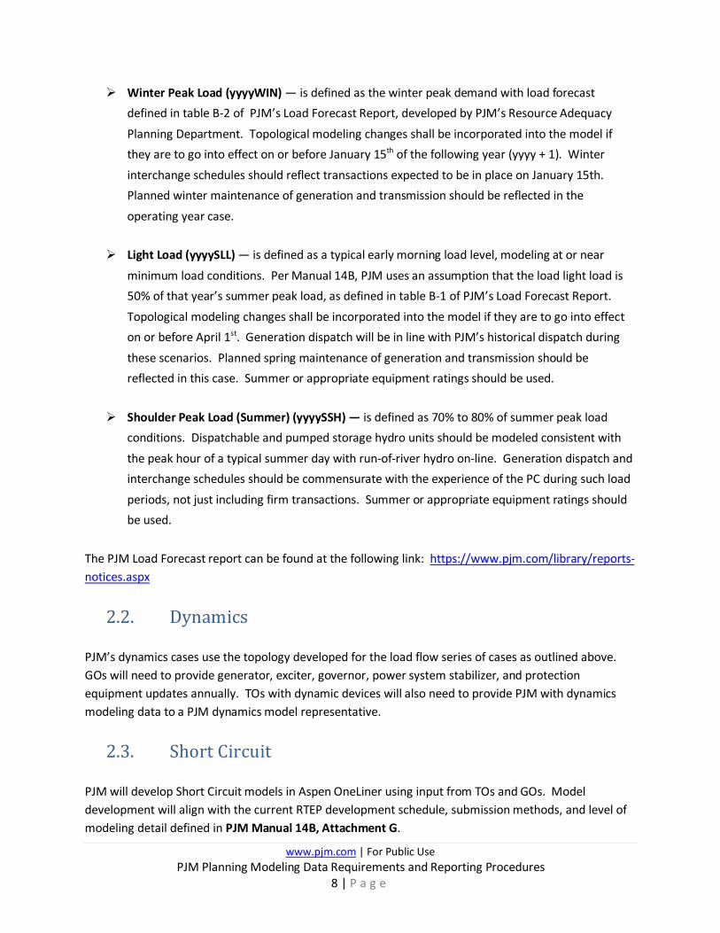
Winter Peak Load (yyyyWIN) — is defined as the winter peak demand with load forecast defined in table B-2 of PJM’s Load Forecast Report, developed by PJM’s Resource Adequacy
Planning Department. Topological modeling changes shall be incorporated into the model if they are to go into effect on or before January 15th of the following year (yyyy + 1). Winter
interchange schedules should reflect transactions expected to be in place on January 15th. Planned winter maintenance of generation and transmission should be reflected in the
operating year case. Light Load (yyyySLL) — is defined as a typical early morning load level, modeling at or near
minimum load conditions. Per Manual 14B, PJM uses an assumption that the load light load is 50% of that year’s summer peak load, as defined in table B-1 of PJM’s Load Forecast Report.
Topological modeling changes shall be incorporated into the model if they are to go into effect on or before April 1st. Generation dispatch will be in line with PJM’s historical dispatch during
these scenarios. Planned spring maintenance of generation and transmission should be reflected in this case. Summer or appropriate equipment ratings should be used.
Shoulder Peak Load (Summer) (yyyySSH) — is defined as 70% to 80% of summer peak load
conditions. Dispatchable and pumped storage hydro units should be modeled consistent with
the peak hour of a typical summer day with run-of-river hydro on-line. Generation dispatch and interchange schedules should be commensurate with the experience of the PC during such load
periods, not just including firm transactions. Summer or appropriate equipment ratings should be used.
The PJM Load Forecast report can be found at the following link: https://www.pjm.com/library/reports-notices.aspx
2.2. Dynamics PJM’s dynamics cases use the topology developed for the load flow series of cases as outlined above. GOs will need to provide generator, exciter, governor, power system stabilizer, and protection equipment updates annually. TOs with dynamic devices will also need to provide PJM with dynamics modeling data to a PJM dynamics model representative.
2.3. Short Circuit PJM will develop Short Circuit models in Aspen OneLiner using input from TOs and GOs. Model development will align with the current RTEP development schedule, submission methods, and level of modeling detail defined in PJM Manual 14B, Attachment G.
www.pjm.com | For Public Use PJM Planning Modeling Data Requirements and Reporting Procedures
9 | P a g e
2.4. Document Organization For convenience, the remainder of this document is divided into two sections. The first section is for Generator Owners and second section is for Transmission Owners.

www.pjm.com | For Public Use PJM Planning Modeling Data Requirements and Reporting Procedures
10 | P a g e
3. Generator Owners A GO, according to NERC is an “entity that owns and maintains generating units”. Concerning MOD-032, GOs are responsible for submitting modeling data for existing generating units in Gen Model. PJM asks that all generators with capacity in PJM markets or having machines over 20 MW submit data via Gen Model. This data will aid PJM in building steady state, dynamics, and short circuit cases.
3.1. Schedule PJM opens a Gen Model window annually on May 1 and the window remains open for 45 calendar days. All in-service generation facilities 20 MW or greater are required to update or submit data during this window. Data for generators that have executed ISAs, but have not begun operating will be extracted from Queue Point, PJM’s data tool for the interconnection study process.
3.1.1. As-Built Submittals (required for post-interconnection for new generators or increased generator capability)
If a PJM queue project with new capability must submit as-built data per its ISA requirement during the Gen Model window, then the GO may submit its as-built data directly into Gen Model and this submittal will meet both the as-built requirement and the annual data submittal requirement. If a PJM queue project with new capability is required to submit as-built data outside of the PJM annual Gen Model window, then the GO must submit “as-built” per the ISA requirements into PJM Queue Point. Regardless of the duration between the initial as-built submittal and the Gen Model window, the GO must submit data into Gen Model at the first window opening. PJM provides instruction to transfer the as-built data from queue point into Gen Model in the Gen Model User Guide (see link below).
The GO must review and verify the data transferred to Gen Model for accuracy and update as required. For example, if a new generator submits as-built data to PJM’s Queue Point as stipulated by its agreement on April 30 and the MOD-032 window opens on May 1, then they must also transfer the Queue Point data to Gen Model as their first MOD-032 submittal. For all subsequent years, the GO is required to update and confirm their data via Gen Model.
3.1.2. Annual Gen Model Window Submittals Every year, PJM provides GOs a time window to submit data. The GO data submittal window opens on May 1 and is open for 45 calendar days. To submit or transfer MOD-032 data to PJM, GOs will have to create a login account for pjm.com and request access to Gen Model via their Company Account Manager (CAM). Refer to Appendix 2: Generator Owner Data Sheet Requirements for a list of
www.pjm.com | For Public Use PJM Planning Modeling Data Requirements and Reporting Procedures
11 | P a g e
required data. Gen Model can be accessed via the PJM Planning Center: https://pjm.com/markets-and-operations/etools/planning-center.aspx Generator Owners have to provide dynamics data in Siemens PTI PSS/E Dynamics Model Raw Data File (.dyr) format. This includes submitting all applicable dynamic model data via the Gen Model portal.
The user guide for “Gen Model” can be accessed here: http://www.pjm.com/~/media/etools/planning-center/gen-model-user-guide.ashx
3.2. Applicability Generation Owners participating in PJM’s wholesale market and meet either criteria below must submit data to PJM:
• Generators with capacity in PJM markets • Generators with 20 MW or greater individual nameplate capacity
• NERC MOD-032 applicable generators
3.3. Power Flow The load flow files developed for PJM’s RTEP and MOD-032 compliance are built using Siemens PTI PSS/E and Model on Demand software. PJM collects data from GOs at specific seasonal assumptions as identified in Gen Model document: http://www.pjm.com/~/media/etools/planning-center/gen-model-user-guide.ashx.
3.4. Dynamics PJM dynamics cases will use the topology developed for the load flow series of cases as outlined above. GOs will need to provide generator, exciter, governor, power system stabilizer, and protection equipment updates annually. Dynamics data is to be submitted via Gen Model in Siemens PTI PSS/E Dynamics Model Raw Data File (.dyr) format. Any changes year to year would require an update uploaded via Gen Model. If a change from previously provided .dyr data is submitted, additional justification must be provided in the form of Excel, Word or Portable Document Format (pdf) documents. These changes must also be reviewed and approved through PJM’s dynamic model verification process under MOD-026 and MOD-027.
www.pjm.com | For Public Use PJM Planning Modeling Data Requirements and Reporting Procedures
12 | P a g e
3.4.1. Modeling Level of Detail Generation Owners are required to provide data for the following (if applicable):
• Generator model
• Excitation System model
• Governor model
• Power System Stabilizer model
• Reactive Line Drop Compensation model
3.4.2. Accepted Dynamics Models PJM follows NERC and MMWG practices in regards to dynamic model requirements. For reference the latest MMWG Procedural Manual can be found at the Reliability First website: https://rfirst.org/ProgramAreas/RAPA/ERAG/MMWG PJM accepts models that are on NERC’s Acceptable Models list. This information is available on the NERC website: https://www.nerc.com/pa/RAPA/ModelAssessment/Pages/default.aspx Other models will only be accepted with a valid technical justification and proper documentation.
3.4.3. Dynamics Data Checks, Initialization, and Acceptance PJM follows the MMWG practice in regards to dynamic data checks. More detailed information can be found in the MMWG Procedural Manual.
3.5. Short Circuit PJM will develop Short Circuit models in Aspen OneLiner using input from GOs. Data provided by our members is preferred in the Aspen format. Model development will align with the current RTEP development schedule, submission methods, and level of modeling detail defined in PJM Manual 14B, Attachment G. GO data collection for short circuit cases will occur in the annual Gen Model window.
www.pjm.com | For Public Use PJM Planning Modeling Data Requirements and Reporting Procedures
13 | P a g e
4. Transmission Owners A TO according to NERC is defined as, “the entity that owns and maintains transmission facilities.” Concerning MOD-032, TOs are responsible to submit modeling data for their existing and future transmission assets. The TOs that are required to submit all data contained in MOD-032-1 Attachment 1 must meet the following criteria: 1. NERC registered Transmission Owners 2. Signatory of the PJM Consolidated Transmission Owners Agreement (CTOA) TOs are required to submit and coordinate shared facility (or tie line) data. They also will submit system topology information using the current Siemens Model on Demand (MoD) production system at PJM, such that each scenario listed in Section 2.1 can be built. Once the load flow cases are created using Model on Demand, TOs will review their respective system topology for accuracy and provide any updates as necessary. TOs are required to provide data for short circuit case builds. TOs are expected to provide dynamics modeling information for any dynamics devices they own. Any TOs that serve external area load via their transmission system, should coordinate with that company and include in its data submission. TOs that have facilities that meet the definition of NERC BES are responsible to provide PJM the necessary planning modeling information per MOD-032 data requirements. If a PJM TO owns any non-BES facilities supplied from NERC BES facilities that are owned by another existing PJM TO, the PJM TO with the non-BES facility must continue to provide planning modeling details to the responsible NERC BES TO. Refer to Appendix 3 for more information on the delineation between Non-BES and BES Modeling Responsibilities with respect to applicable PJM TOs. PJM’s FERC Order 1000 process (Refer to PJM Manual 14F) may result in non-incumbent transmission developers being awarded transmission facilities to engineer, construct, own, operate, and maintain. These non-incumbent transmission developers that are awarded projects through PJM’s FERC Order 1000 window process shall provide all necessary modeling data for their project via a PSSE response file (*.idv). PJM will ensure that this idv is included in future case builds. Additional model support by the non-incumbent transmission developers such as creating contingencies, verifying the existing model, and providing any annual updates or changes are also required. The non-incumbent transmission developer can have the incumbent TOs, or other PJM member TOs provide modeling support on their behalf if it is agreed upon between those entities. Due to the fact that non-incumbent transmission developers cannot sign the CTOA until 45 days prior to energization, both parties must provide modeling data and tie-in details to PJM.

www.pjm.com | For Public Use PJM Planning Modeling Data Requirements and Reporting Procedures
14 | P a g e
If FERC Order 1000 project is awarded to an existing PJM Transmission Owner, project information will be submitted through Model on Demand similar to the process for other baseline projects. Any questions and updates should be sent to [email protected].
4.1. Power Flow Cases 4.1.1. Schedule
Task Anticipated Annual Completion Month
Additional Comments
Kick off Conference Call February Tie line update May Interchange Update May Build Cases to be submitted for Trial 1 in MOD
May Cases assembled by PJM in MOD based on latest available base case and project file information and disseminated to TOs by PJM
Case updates to Trial 1 July Finalize Tie line and Interchange
August
Case updates to Trial 2 August Case updates to Trial 3 September Post Final Cases October
4.1.2. Format Power Flow data for MOD-032 compliance will be uploaded via PJM’s implementation of the Siemens/PTI software Model on Demand. Every Transmission Owner responsible for submitting MOD-032 data to PJM will have access to Model on Demand in order to upload project files and profile files to allow PJM to build the years and scenarios as defined by the NERC designee. A project (.prj) file will model future changes in transmission system topology, correct case modeling, and future generation projects. Profile files (.raw) model load profile and device settings on regulating equipment. Equipment ratings will be uploaded via comma separated value (.csv) format into Model on Demand. Until becoming a TO as defined in Section 4, any non-incumbent transmission developers awarded projects through PJM’s FERC Order 1000 window process shall provide modeling data for their project through a PSS/E response file (*.idev). This submission shall be verified/updated annually. Once the
www.pjm.com | For Public Use PJM Planning Modeling Data Requirements and Reporting Procedures
15 | P a g e
non-incumbent transmission developer is registered by NERC as a Transmission Owner and Signatory of the PJM Consolidated Transmission Owners Agreement (CTOA), modeling data shall be provided through Model on Demand by the non-incumbent transmission developer. Additional model support by the non-incumbent transmission developers such as creating contingencies, verifying the existing model, and providing any annual updates or changes are also required. The non-incumbent transmission developer can have the incumbent TOs, or other PJM member TOs provide modeling support on their behalf if it is agreed upon between those entities. Non-incumbent transmission developers cannot sign the CTOA until 45 days prior to energization therefore, both parties must provide modeling data and tie-in details to PJM. If FERC Order 1000 project is awarded to an existing PJM Transmission Owner, project information will be submitted through Model on Demand similar to the process for other baseline projects. Any questions and updates should be sent to [email protected].
4.1.3. Level of Detail The minimum level of detail that must be uploaded to Model on Demand in order to be included in steady state cases for MOD-032 compliance is: Included in Model on Demand base case or in project files:
• Bulk Electric System and PJM Market Monitored facilities o Sub-BES facilities can be included at TO discretion
• All PJM Board approved Baseline projects
• All Supplemental projects submitted to the Local Plan
• Interconnection projects with an executed ISA and their network upgrades o PJM as RP will coordinate with TO’s for project modeling
Included in Model on Demand profile files:
• Load profile for each season o PJM will scale load based on its load forecast as described in section 2.1
o It is expected that distribution owners will coordinate with their TO to provide load profile data
• TOs that serve external area load via their transmission system should coordinate with that company and include in its data submission
• Device profile containing settings on equipment such as transformers, shunts, HVDC data, etc.
More in depth detail on individual equipment can be found in Appendix 1: Detailed Data Requirements for Steady State.

www.pjm.com | For Public Use PJM Planning Modeling Data Requirements and Reporting Procedures
16 | P a g e
4.1.4. Power Flow via Model On Demand PJM currently uses the Siemens Model on Demand tool for creation and maintenance of its load flow planning models. Each registered PJM TO member company that is involved with the model can have as many users as it deems necessary, with one or two people being that TOs administrator in charge of approving its areas projects. Note that all personnel being granted access must have CEII clearances. If a PJM TO Member Company elects to have an agent submit data on their behalf, then a Declaration of Authority is required. Because Model on Demand licenses are by company, if an Agent is used, then only the Agent company representatives will have access to Model on Demand. PJM then will review and accept each submission before the projects are included in case builds. For any user issues, contact [email protected].
4.1.5. Tie-Lines PJM will maintain a list of tie facilities (lines and transformers) to be used in the creation of steady state and dynamics models. It will be distributed to the TOs at the beginning of each year’s build cycle for updates. PJM will maintain data for intra-PJM ties between its TOs and Inter-PJM ties with other PCs.
1) Ties will only be included in steady state and dynamics models if they are included in the tie list
2) The bus names and associated data in steady state and dynamics models should match those in the tie list
3) Tie lines must be agreed upon by applicable TOs in order to be included 4) Tie facility modeling should be consistent with the data requirements in Appendix 1:
Detailed Data Requirements for Steady State 5) Include in service and out of commission dates for tie lines and transformers
6) Tie facility list will be updated annually at the beginning of the case build cycle 7) TOs should only submit changes to the tie line database
8) Ties with an in-service/out-of-service date from 01/16/yyyy to 04/15/yyyy will be in-service/out-of-service in the spring model for the year yyyy.
9) Ties with an in-service/out-of-service date from 04/16/yyyy to 06/01/yyyy will be in-service/out-of-service in the summer model for the year yyyy.
10) Ties with an in-service/out-of-service date from 06/02/yyyy to 10/15/yyyy will be in-service/out-of-service in the fall model for the year yyyy.
www.pjm.com | For Public Use PJM Planning Modeling Data Requirements and Reporting Procedures
17 | P a g e
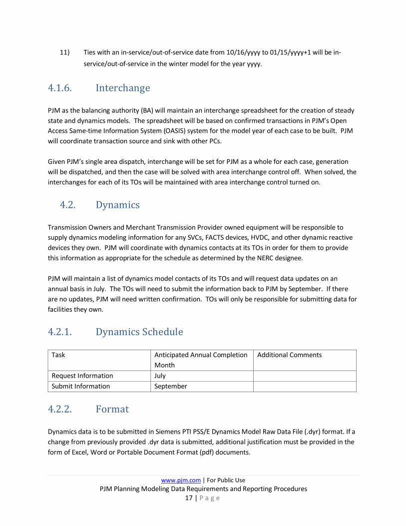
11) Ties with an in-service/out-of-service date from 10/16/yyyy to 01/15/yyyy+1 will be in-service/out-of-service in the winter model for the year yyyy.
4.1.6. Interchange PJM as the balancing authority (BA) will maintain an interchange spreadsheet for the creation of steady state and dynamics models. The spreadsheet will be based on confirmed transactions in PJM’s Open Access Same-time Information System (OASIS) system for the model year of each case to be built. PJM will coordinate transaction source and sink with other PCs. Given PJM’s single area dispatch, interchange will be set for PJM as a whole for each case, generation will be dispatched, and then the case will be solved with area interchange control off. When solved, the interchanges for each of its TOs will be maintained with area interchange control turned on.
4.2. Dynamics Transmission Owners and Merchant Transmission Provider owned equipment will be responsible to supply dynamics modeling information for any SVCs, FACTS devices, HVDC, and other dynamic reactive devices they own. PJM will coordinate with dynamics contacts at its TOs in order for them to provide this information as appropriate for the schedule as determined by the NERC designee. PJM will maintain a list of dynamics model contacts of its TOs and will request data updates on an annual basis in July. The TOs will need to submit the information back to PJM by September. If there are no updates, PJM will need written confirmation. TOs will only be responsible for submitting data for facilities they own.
4.2.1. Dynamics Schedule
Task Anticipated Annual Completion Month
Additional Comments
Request Information July Submit Information September
4.2.2. Format Dynamics data is to be submitted in Siemens PTI PSS/E Dynamics Model Raw Data File (.dyr) format. If a change from previously provided .dyr data is submitted, additional justification must be provided in the form of Excel, Word or Portable Document Format (pdf) documents.
www.pjm.com | For Public Use PJM Planning Modeling Data Requirements and Reporting Procedures
18 | P a g e
4.2.3. Dynamic Load Model Data To meet TPL-001-4 R2.4.1 standard, PJM requires TOs develop and submit dynamic load models satisfying the following conditions:
• Submitted load models shall be under system peak load conditions
• Submitted load models shall represent dynamic behavior of loads
• Submitted load models shall consider dynamics of induction motor loads
• Submitted load models shall cover all load buses in TO’s area
• Submitted load models shall be usable: o Model shall initialize without error
o Model shall results in negligible transients for a no-disturbance o Model shall results in stable behavior for a stable disturbance
An aggregate System Load model which represents the overall dynamic behavior of the Load is acceptable.
4.2.4. Accepted Dynamics Models PJM follows NERC and MMWG practices in regards to dynamic model requirements. For reference the latest MMWG Procedural Manual can be found at the Reliability First website: https://rfirst.org/ProgramAreas/RAPA/ERAG/MMWG PJM accepts models that are on NERC’s Acceptable Models list. This information is available on the NERC website: https://www.nerc.com/pa/RAPA/ModelAssessment/Pages/default.aspx ‘ Other models will only be accepted with a valid technical justification and proper documentation.
4.2.5. Dynamics Data Checks, Initialization, and Acceptance PJM follows MMWG practice in regards to dynamic data checks. More detailed information can be found in the MMWG Procedural Manual.
4.3. Short Circuit
4.3.1. Schedule The short circuit schedule presented below keeps with the current RTEP development cycle. The schedule set out by the NERC designee makes this schedule subject to change. If the designee requests

www.pjm.com | For Public Use PJM Planning Modeling Data Requirements and Reporting Procedures
19 | P a g e
a case, PJM will request TOs to review and provide feedback on a 2 and/or 5 year case based on the NERC designee request.
Two Year Out Case Build
Task Anticipated Annual Completion Month
Additional Comments
Send out Draft (Previous Year) Case
August
Receive Updates September Case Updates to Trial 1 January Case Updates to Trial 2 January/February Case Updates to Trial 3 March/April Finalize Case April
Five Year Out Case Build
Task Anticipated Annual Completion Month
Additional Comments
Send out Trial 1 case (based on final year 2 case)
February/March
Receive and apply updates March/April Finalize Case April
4.3.2. Format PJM uses Aspen Oneliner as its short circuit modeling and analysis software which uses .olr format. For TOs using Aspen, data shall be submitted either via .olr or change file (.chf) format. For TOs using Siemens PTI PSS CAPE software, topology changes will be accepted in .dxt format and breaker changes will be accepted via spreadsheet.
4.3.3. Short Circuit Level of Detail Included in base case or in project files:
• Bulk Electric System and PJM Market Monitored facilities o Sub-BES facilities can be included at TO discretion
• All PJM Board approved Baseline projects
• All supplemental projects submitted to the Local Plan
• Interconnection projects with an executed ISA and their network upgrades o PJM as RP will coordinate with TOs for project modeling

www.pjm.com | For Public Use PJM Planning Modeling Data Requirements and Reporting Procedures
20 | P a g e
4.3.4. Short Circuit Submittal Procedure
PJM will maintain short circuit modeling contacts with each of its TOs. PJM will send out the previous year’s short circuit case and will ask for updates in the data formats outlined above to be emailed back according to that year’s model build schedule. An anticipated short circuit build schedule is included in Section 4.3.1.

www.pjm.com | For Public Use PJM Planning Modeling Data Requirements and Reporting Procedures
21 | P a g e
5. Appendix 1: Generator Owner Data Requirements
Applicable Generator Owners are required to submit their data for MOD-032 requirements into the Gen Model portal. Please refer to the most recent version of the Gen Model Form Spreadsheet, which clearly indicate the data requirements. All the applicable values are included in this spreadsheet. https://pjm.com/-/media/etools/planning-center/read-only-2021-gen-model-form-spreadsheet.ashx
www.pjm.com | For Public Use PJM Planning Modeling Data Requirements and Reporting Procedures
22 | P a g e
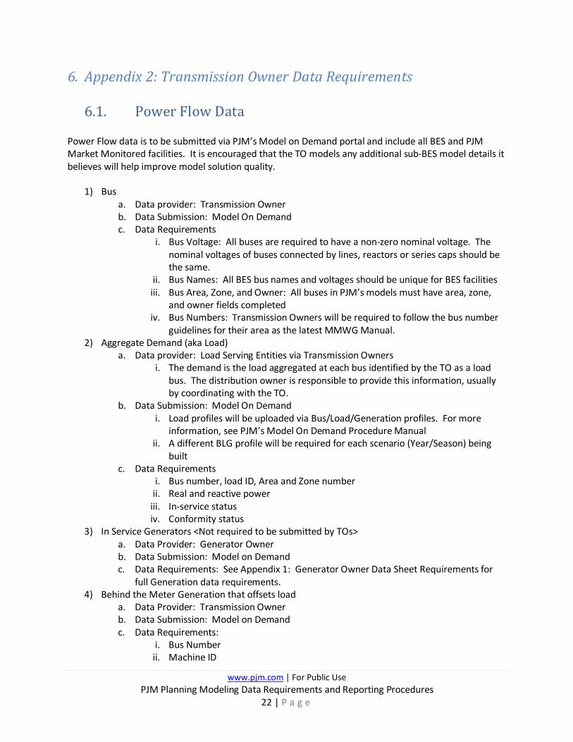
6. Appendix 2: Transmission Owner Data Requirements
6.1. Power Flow Data Power Flow data is to be submitted via PJM’s Model on Demand portal and include all BES and PJM Market Monitored facilities. It is encouraged that the TO models any additional sub-BES model details it believes will help improve model solution quality.
1) Bus a. Data provider: Transmission Owner b. Data Submission: Model On Demand c. Data Requirements
i. Bus Voltage: All buses are required to have a non-zero nominal voltage. The nominal voltages of buses connected by lines, reactors or series caps should be the same.
ii. Bus Names: All BES bus names and voltages should be unique for BES facilities iii. Bus Area, Zone, and Owner: All buses in PJM’s models must have area, zone,
and owner fields completed iv. Bus Numbers: Transmission Owners will be required to follow the bus number
guidelines for their area as the latest MMWG Manual. 2) Aggregate Demand (aka Load)
a. Data provider: Load Serving Entities via Transmission Owners i. The demand is the load aggregated at each bus identified by the TO as a load
bus. The distribution owner is responsible to provide this information, usually by coordinating with the TO.
b. Data Submission: Model On Demand i. Load profiles will be uploaded via Bus/Load/Generation profiles. For more
information, see PJM’s Model On Demand Procedure Manual ii. A different BLG profile will be required for each scenario (Year/Season) being
built c. Data Requirements
i. Bus number, load ID, Area and Zone number ii. Real and reactive power iii. In-service status iv. Conformity status
3) In Service Generators <Not required to be submitted by TOs> a. Data Provider: Generator Owner b. Data Submission: Model on Demand c. Data Requirements: See Appendix 1: Generator Owner Data Sheet Requirements for
full Generation data requirements. 4) Behind the Meter Generation that offsets load
a. Data Provider: Transmission Owner b. Data Submission: Model on Demand c. Data Requirements:
i. Bus Number ii. Machine ID
www.pjm.com | For Public Use PJM Planning Modeling Data Requirements and Reporting Procedures
23 | P a g e
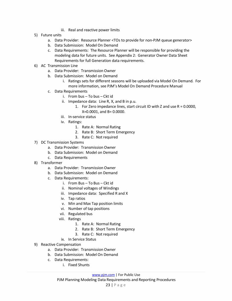
iii. Real and reactive power limits 5) Future units
a. Data Provider: Resource Planner <TOs to provide for non-PJM queue generator> b. Data Submission: Model On Demand c. Data Requirements: The Resource Planner will be responsible for providing the
modeling data for future units. See Appendix 2: Generator Owner Data Sheet Requirements for full Generation data requirements.
6) AC Transmission Line a. Data Provider: Transmission Owner b. Data Submission: Model on Demand
i. Ratings sets for different seasons will be uploaded via Model On Demand. For more information, see PJM’s Model On Demand Procedure Manual
c. Data Requirements i. From bus – To bus – Ckt id
ii. Impedance data: Line R, X, and B in p.u. 1. For Zero impedance lines, start circuit ID with Z and use R = 0.0000,
X=0.0001, and B= 0.0000. iii. In-service status iv. Ratings:
1. Rate A: Normal Rating 2. Rate B: Short Term Emergency 3. Rate C: Not required
7) DC Transmission Systems a. Data Provider: Transmission Owner b. Data Submission: Model on Demand c. Data Requirements
8) Transformer a. Data Provider: Transmission Owner b. Data Submission: Model on Demand c. Data Requirements:
i. From Bus – To Bus – Ckt id ii. Nominal voltages of Windings iii. Impedance data: Specified R and X iv. Tap ratios v. Min and Max Tap position limits
vi. Number of tap positions vii. Regulated bus
viii. Ratings 1. Rate A: Normal Rating 2. Rate B: Short Term Emergency 3. Rate C: Not required
ix. In Service Status 9) Reactive Compensation
a. Data Provider: Transmission Owner b. Data Submission: Model On Demand c. Data Requirements:
i. Fixed Shunts

www.pjm.com | For Public Use PJM Planning Modeling Data Requirements and Reporting Procedures
24 | P a g e
1. G-Shunt (MW) 2. B-Shunt (MVAr) 3. In-service Status
ii. Switched Shunts 1. Voltage Limits (Vhi and Vlow) 2. Mode of Operation (Fixed, Discrete, Continuous) 3. Regulated Bus (If not fixed) 4. Binit (MVAr) 5. Steps and Step Sizes (MVAr)
10) Static Var Systems a. Data Provider: Transmission Owner b. Data Submission: Model on Demand c. Data Requirements
i. Reactive limits ii. Voltage set point
iii. Fixed/switched shunt, if applicable iv. In-service status
6.2. Short Circuit Data
1) Bus a. Data provider: Transmission Owner b. Data Submission: Email c. Data Requirements:
i. Bus Voltage: All buses are required to have a non-zero nominal voltage. The nominal voltages of buses connected by lines, reactors or series caps should be the same.
ii. Bus Names: All BES bus names and voltages should be unique for BES facilities iii. Bus Numbers: At least one bus at each substation should be numbered
matching the guidelines for their area in the latest MMWG Manual. This bus number should map to that same substation in the steady state model.
2) Generating Units a. Existing Units <Not required to be submitted by TOs>
i. Data Provider: Generator Owner ii. Not Data Submission: Gen Model iii. Data Requirements: See Appendix 2: Generator Owner Data
Requirements for full Generation data requirements. b. Behind the Meter Units
i. Data Provider: Transmission Owner ii. Data Submission: Model On Demand iii. Data Requirements: See Appendix 2: Generator Owner Data
Requirements for full Generation data requirements. c. Future Units
i. Data Provider: Resource Planner (TO responsible for non-PJM queue generation)
ii. Data Submission: Model On Demand

www.pjm.com | For Public Use PJM Planning Modeling Data Requirements and Reporting Procedures
25 | P a g e
iii. Data Requirements: The Resource Planner will be responsible for providing the modeling data for future units. See Appendix 2: Generator Owner Data Requirements for full Generation data requirements.
3) AC Transmission Line a. Data Provider: Transmission Owner b. Data Submission: Email c. Data Requirements
i. From bus – To bus – Ckt id ii. Impedance data: Line R, X, and B in p.u.
1. Line R, X, and B in p.u. 2. Positive, Negative, zero sequence data
iii. In-service status 4) DC Transmission Systems
a. Data Provider: Transmission Owner b. Data Submission: Model On Demand c. Data Requirements
5) Transformer a. Data Provider: Transmission Owner b. Data Submission: Model On Demand c. Data Requirements:
i. From Bus – To Bus – Ckt id ii. Nominal voltages of Windings iii. Impedance data: Specified R and X
3. Positive, Negative, zero sequence data
6) Circuit Breakers a. Data Provider: Transmission Owners b. Data Submission: Email c. Data Requirements: For each BES circuit breaker the following data must be included in
the data submittal: I. Substation & Bus Name
II. Breaker Name III. Manufacturer IV. Model Number V. Nameplate Interrupting Rating (kA or MVA)
VI. Nameplate Interrupting Time (Cycles) VII. Nameplate K-factor
VIII. Operating Voltage (kV) IX. Nameplate Max Design kV (kV) X. Contact Parting Time (Cycles)
XI. Reclosing Time (Number of Cycles & reclosing time in seconds) XII. Protective Equipment 1 (e.g. generator, line, transformer)
a. Specify specific protective equipment name (e.g. Peach Bottom unit 2 Generator, TMI- Hosensack 500 kV Circuit 1 Line)
XIII. Protective Equipment 2 (e.g. generator, line, transformer)
www.pjm.com | For Public Use PJM Planning Modeling Data Requirements and Reporting Procedures
26 | P a g e
a. Specify specific protective equipment name (e.g. Peach Bottom unit 2 Generator, TMI- Hosensack 500 kV Circuit 1 Line)
XIV. Interrupting Medium (e.g. Gas, Oil, Air, etc.) Does this breaker get de-rated? (yes or no)
www.pjm.com | For Public Use PJM Planning Modeling Data Requirements and Reporting Procedures
27 | P a g e
7. Appendix 3: BES and Non-BES Demarcation Guidance for MoD
7.1. Criteria for PJM TO Entities to Submit Data into Siemens Model On Demand (MoD)
All entities meeting the following criteria must submit MOD-032 data directly to Model on Demand:
• NERC registered Transmission Owner, and
• Signatory of the PJM Consolidated Transmission Owners Agreement
TOs that have facilities that meet the definition of NERC BES are responsible to provide PJM the necessary planning modeling information per MOD-032 data requirements. If a PJM TO owns any non-BES facilities supplied from NERC BES facilities that are owned by another existing PJM TO, the PJM TO with the non-BES facility must continue to provide planning modeling details to the responsible NERC BES TO. Examples of different scenarios are shown in Section 7.4 and 7.5.
7.2. Additional Modeling Considerations
There are two classification types of PJM Transmission Owners for the purpose of this document – incumbent and non-incumbent.
• Incumbent TOs are defined as TOs represented under their own “Area” number in the load flow model per MMWG modeling standards.
• Non-Incumbent TOs are defined as those that are geographically located within the “Area” of an Incumbent TO (has its own “Area” number in the load flow model). Instead of being assigned a separate “Area” number in the model, non-incumbent TOs will have their “Owner” number within the existing “Area” hierarchy.
Applicable facilities (buses, etc.) that are needed for the model will be maintained by the TO (both non-Incumbent and Incumbent) under its own unique “Owner(s)” number in PSS/E under the existing “Area” hierarchy. For non-incumbent TOs - PJM requires further justification for modeling exceptions such as buses below 100 kV to be included under their Owner number to ensure that they meet the NERC BES definition.
NERC Reference Guide (Provides BES vs. Non-BES Guidance) https://www.nerc.com/pa/Stand/Project%20201017%20Proposed%20Definition%20of%20Bulk%20Electri/bes_phase2_reference_document_20140325_final_clean.pdf

www.pjm.com | For Public Use PJM Planning Modeling Data Requirements and Reporting Procedures
28 | P a g e
7.3. Accepting Changes from PJM Non-Incumbent TOs
Non-Incumbent TOs need to ensure that any .prj file correctly identifies the correct Owner bus numbers are included in the change file. Only the new BES buses (and applicable non-BES buses as clarified in the examples) that are under its MOD-032 modeling jurisdiction should use its owner number. The remainder of the buses not under its MOD-032 modeling jurisdiction and required for modeling should use and/or remain that of the incumbent TO owner number. An error with the Owner Numbers will cause issues when submitting into MoD.
For PJM approved baseline projects that are under the non-incumbent MOD-032 modeling jurisdiction, the non-incumbent TO should submit that project directly in MoD.
For PJM approved baseline projects that contain non-BES facilities and under the MOD-032 modeling jurisdiction of the incumbent TO, the non-incumbent TO will need to submit the .idv to the incumbent TO for them to submit this project into MoD.
For the competitive process window, the non-incumbent TO should submit an .idv of their project directly to the Transmission Planning group at PJM per the competitive planning process.
7.4. Modeling Responsibilities for Existing Facilities Examples
Notes for all Examples
• The transformers shown represent the full physical transformer, which includes the high and low side bushings, which can be excluded from the BES definition if the low side voltage is less than 100 kV.
• The Yellow Diamond represents the Point of Interconnection (POI). Green coloring is for 138 kV facilities and Orange coloring is for 69 kV facilities.
• Purple Facilities are considered “new or proposed”. • Entity #1 represents an incumbent TO and Entity #2 represents a non-incumbent TO both located
within the same PSS/E Area Number.
www.pjm.com | For Public Use PJM Planning Modeling Data Requirements and Reporting Procedures
29 | P a g e
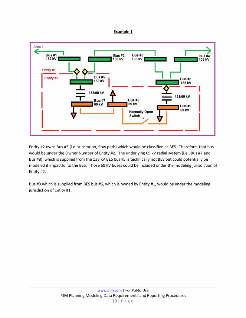
Example 1
Entity #2 owns Bus #5 (i.e. substation, flow path) which would be classified as BES. Therefore, that bus would be under the Owner Number of Entity #2. The underlying 69 kV radial system (i.e., Bus #7 and Bus #8), which is supplied from the 138 kV BES bus #5 is technically not BES but could potentially be modeled if impactful to the BES. Those 69 kV buses could be included under the modeling jurisdiction of Entity #2.
Bus #9 which is supplied from BES bus #6, which is owned by Entity #1, would be under the modeling jurisdiction of Entity #1.
www.pjm.com | For Public Use PJM Planning Modeling Data Requirements and Reporting Procedures
30 | P a g e
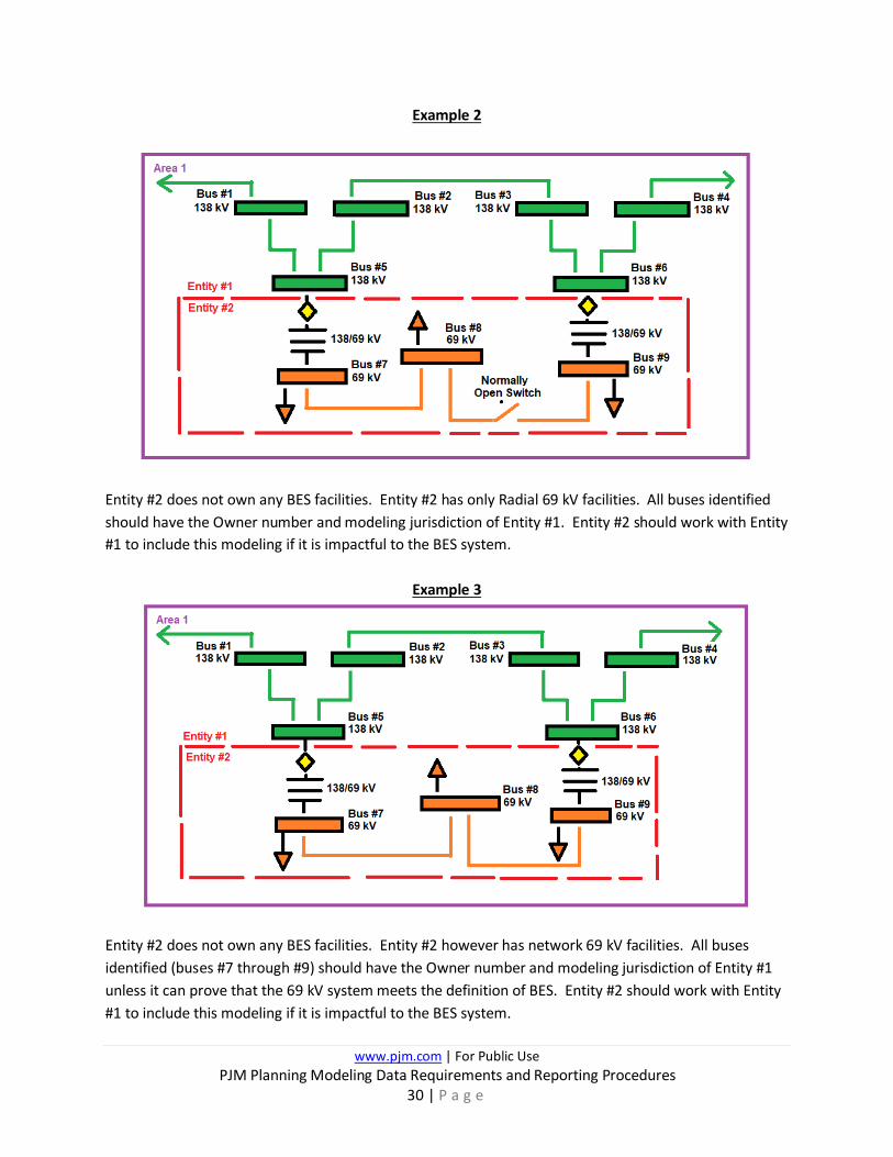
Example 2
Entity #2 does not own any BES facilities. Entity #2 has only Radial 69 kV facilities. All buses identified should have the Owner number and modeling jurisdiction of Entity #1. Entity #2 should work with Entity #1 to include this modeling if it is impactful to the BES system.
Example 3
Entity #2 does not own any BES facilities. Entity #2 however has network 69 kV facilities. All buses identified (buses #7 through #9) should have the Owner number and modeling jurisdiction of Entity #1 unless it can prove that the 69 kV system meets the definition of BES. Entity #2 should work with Entity #1 to include this modeling if it is impactful to the BES system.
www.pjm.com | For Public Use PJM Planning Modeling Data Requirements and Reporting Procedures
31 | P a g e
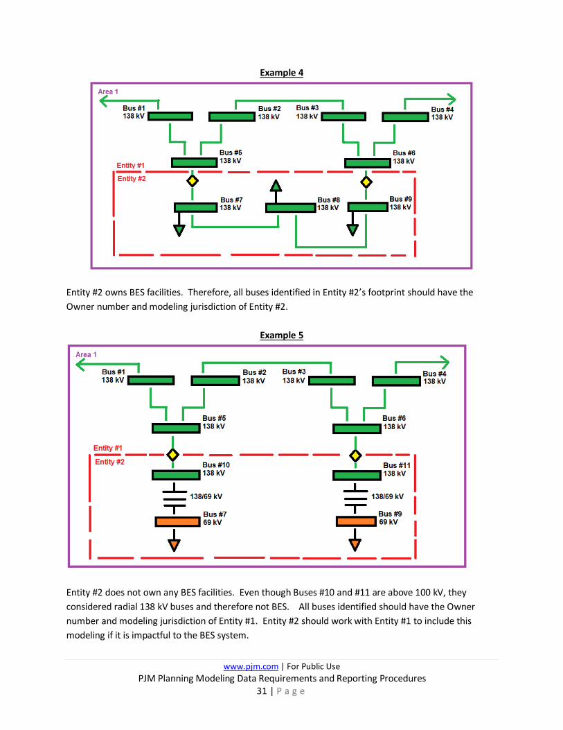
Example 4
Entity #2 owns BES facilities. Therefore, all buses identified in Entity #2’s footprint should have the Owner number and modeling jurisdiction of Entity #2.
Example 5
Entity #2 does not own any BES facilities. Even though Buses #10 and #11 are above 100 kV, they considered radial 138 kV buses and therefore not BES. All buses identified should have the Owner number and modeling jurisdiction of Entity #1. Entity #2 should work with Entity #1 to include this modeling if it is impactful to the BES system.
www.pjm.com | For Public Use PJM Planning Modeling Data Requirements and Reporting Procedures
32 | P a g e
7.5. Modeling Responsibilities for Approved Network Upgrade Projects Examples
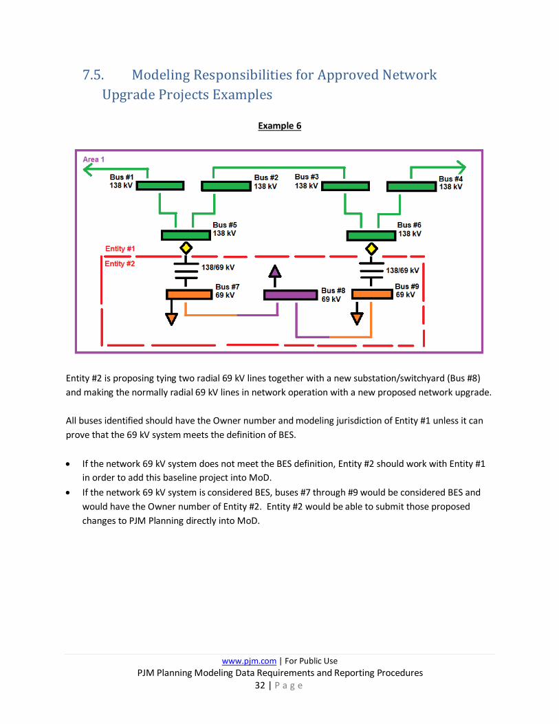
Example 6
Entity #2 is proposing tying two radial 69 kV lines together with a new substation/switchyard (Bus #8) and making the normally radial 69 kV lines in network operation with a new proposed network upgrade. All buses identified should have the Owner number and modeling jurisdiction of Entity #1 unless it can prove that the 69 kV system meets the definition of BES.
• If the network 69 kV system does not meet the BES definition, Entity #2 should work with Entity #1
in order to add this baseline project into MoD. • If the network 69 kV system is considered BES, buses #7 through #9 would be considered BES and
would have the Owner number of Entity #2. Entity #2 would be able to submit those proposed changes to PJM Planning directly into MoD.
www.pjm.com | For Public Use PJM Planning Modeling Data Requirements and Reporting Procedures
33 | P a g e
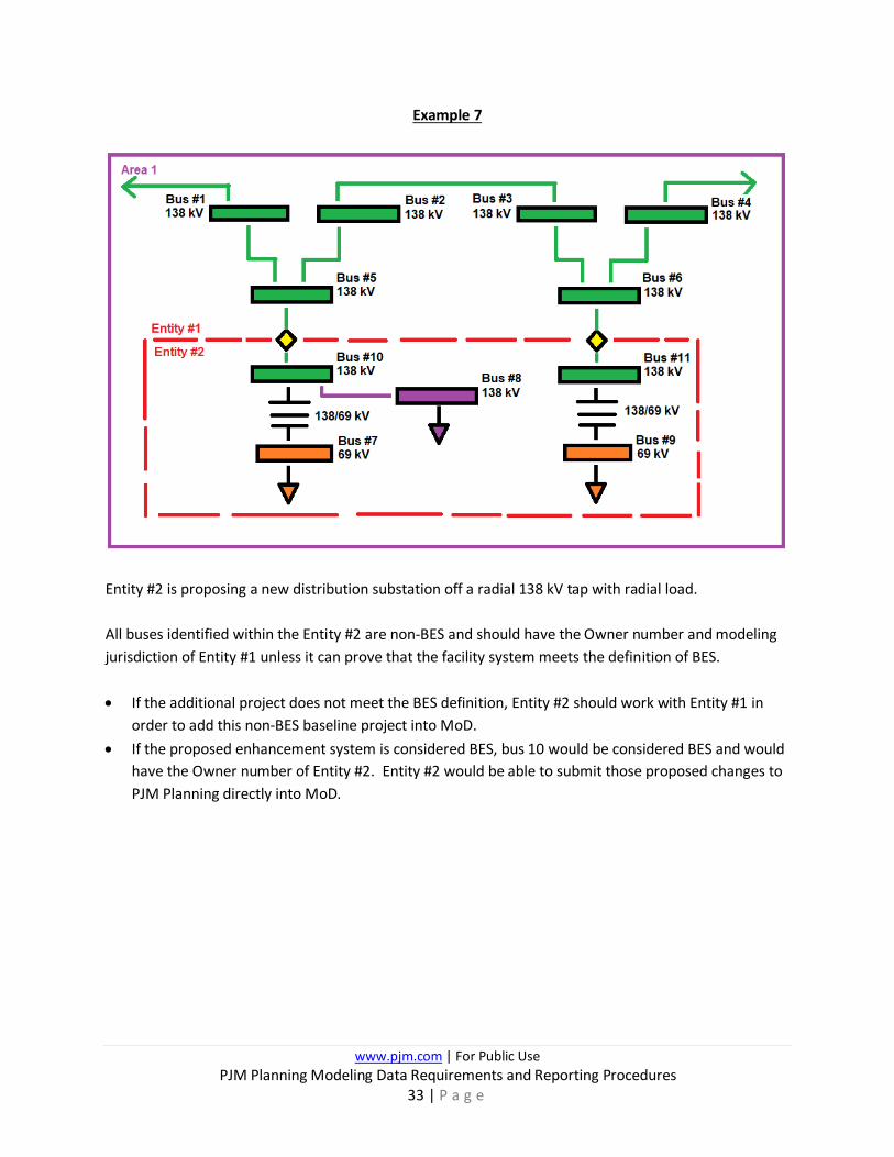
Example 7
Entity #2 is proposing a new distribution substation off a radial 138 kV tap with radial load. All buses identified within the Entity #2 are non-BES and should have the Owner number and modeling jurisdiction of Entity #1 unless it can prove that the facility system meets the definition of BES. • If the additional project does not meet the BES definition, Entity #2 should work with Entity #1 in
order to add this non-BES baseline project into MoD. • If the proposed enhancement system is considered BES, bus 10 would be considered BES and would
have the Owner number of Entity #2. Entity #2 would be able to submit those proposed changes to PJM Planning directly into MoD.

www.pjm.com | For Public Use PJM Planning Modeling Data Requirements and Reporting Procedures
34 | P a g e
Example 8
Entity #2 is proposing adding a distribution substation off a radial 138 kV tap, however in this case networking all the local 69 kV lines together.
All buses identified should have the Owner number and modeling jurisdiction of Entity #1 unless it can prove that the 69 kV network system meets the definition of BES. • If the network 69 kV system does not meet the BES definition, Entity #2 should work with Entity #1
in order to add this baseline project into MoD. • If the network 69 kV system is considered BES, buses #7 through #12 would be considered BES and
would have the Owner number of Entity #2. Entity #2 would be able to submit those proposed changes to PJM Planning directly into MoD.

www.pjm.com | For Public Use PJM Planning Modeling Data Requirements and Reporting Procedures
35 | P a g e
Example 9
Entity #2 is proposing adding a new line for a distribution substation off an initially radial 138 kV tap, however in this case, the new transmission line makes the initial radial tap, networked.
Now that Buses 5 and 6 become BES with the new transmission line, this situation becomes slightly more complicated.
Bus 10 and Bus 11 even though are 138 kV, are still radial and considered non-BES. Therefore, Buses 7, 9, 10, and 11 if modeled should have the Owner number and modeling jurisdiction of Entity #1 unless it can prove that the facility system meets the definition of BES. Bus 8 is part of a network path and therefore would be considered BES. As a result, Bus 12 if modeled should have the Owner number and modeling jurisdiction of Entity #2.
www.pjm.com | For Public Use PJM Planning Modeling Data Requirements and Reporting Procedures
36 | P a g e
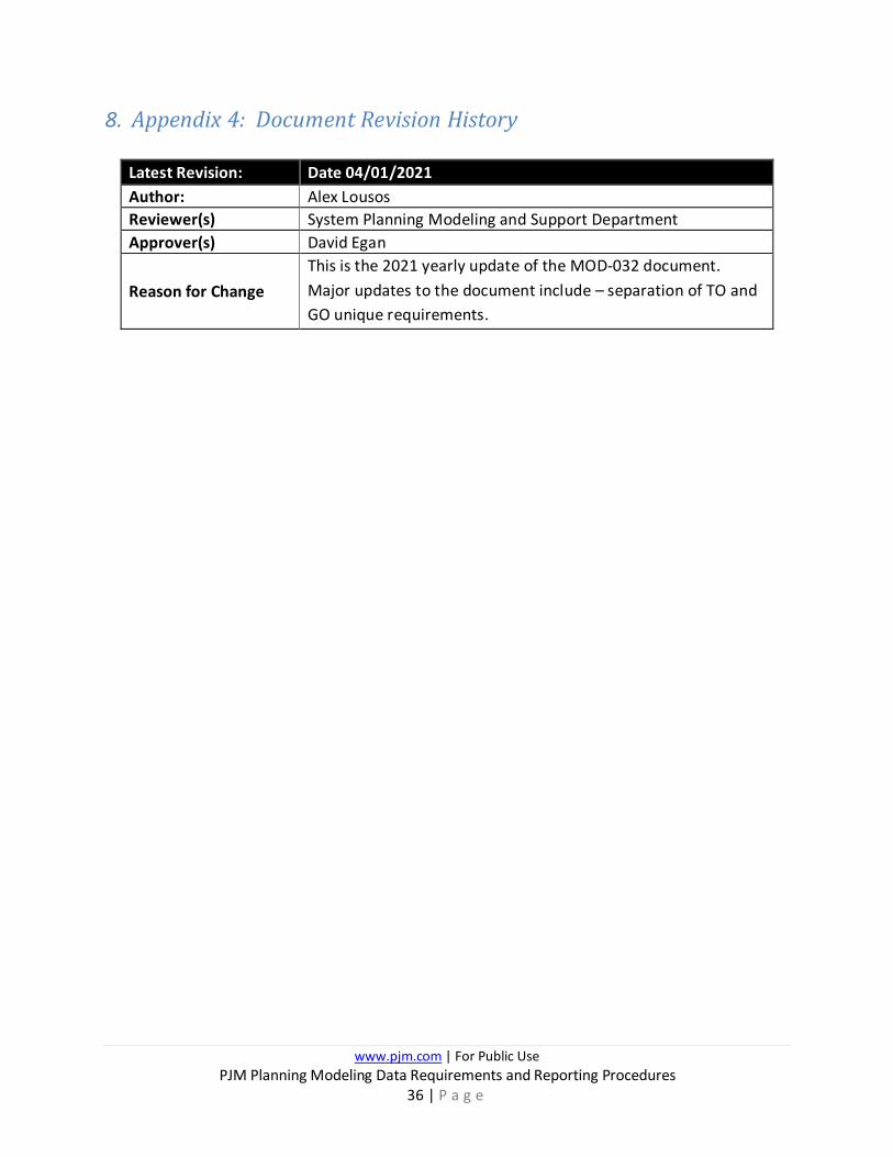
8. Appendix 4: Document Revision History
Latest Revision: Date 04/01/2021 Author: Alex Lousos Reviewer(s) System Planning Modeling and Support Department Approver(s) David Egan
Reason for Change This is the 2021 yearly update of the MOD-032 document. Major updates to the document include – separation of TO and GO unique requirements.