summary - dtic
TRANSCRIPT


SUMMARY
The Purpose of this experiment was to measure the scalins with
distance of the transverse made stimulation in the free electron laser
exPeriment at LURE in Orsay. These experiments were Performed, and the
analysis has revealed that the Phenomenon scales as Predicted b- the
smn ll signal theory. A new effect was observed with a multiple mode
ini ut laier Probe; the theer,, to describe this effect was developed. In
further 3nalysis of data taken Previously, we were also able to
demonstrate the scaling of the transverse oouplinm terms in the gain as
a function of the electron beam size and the resonance parameter.
Our main conclusion from this work is that the size of the
oFF-diaaonal terms in the transverse gain matrix is of the order of
unity if the electron beam and the laser beam sizes are comparable.
Since this situation is lihely to hold for all FEL deviresr transverse
effects cannot in general be neglected. To dater these effects have not
shown up due to the low main of the oscillators which have been
orerated. For devices with a gain of the order of unit ' or higher.
diffractive effects wil) strongly modiF!' the laser mode. Prosrams
devieloping FELs in the high zn resime should he aware of this fact,
and budoet the research time to inve~tieRte the implications to their
Particular confisuration.
This experiment is the first capable of rosolvins an excitation of
I ho higher order transverse modes in a free electron laser, and has
established the existence of oFf-diasonal terms in the transverse gain
matrix. The technique we have developed is the only diasnostic of the
trAnsverse mode mixins effect which can diagnose its Presence in devices
with oPtical sain below aPPn'0:(imately 100% Per Pass.
0r

: J:- : \. , ,---, . :. . i . . ' , , .* . . . . . . . . ': '. i
\ r
INTRODUCTION
The Purpose of this experiment was to obtain some additional
information on the Phenomenon of mode mixins in the FEL, recently
discovered at Orsat' [Appendix I. Ai sinsle transverse mode laser
beam is obserued to Produce stimulated emission into a series of
hisher order modes. We have deveJoped a technique which enables us
to measure this effect. In this work, we have obtained a new set
of data and have been able to show both qualitative and quantitave
9sreement with the theor-? (APPendix II.
Transverse mode mixins is important to the operation of FEL
hish 2ain oscillators and ampliFiers. For low sain systems, the
vector of mode amplitudes and Phases is little chansed in one
Pass, and the Power, which is quadratic in the amplitudes, only
increases noticeably in the modes Populated by the input beam.
Oscillators operated in this resime will show no effects From mode
mixins. At moderate values of sain, the rotation of the input mode
vector can be substantial, resultins in multiple mode output
resardless of the input mode. StorRse rins lasers are expected to
operate in this regime. If the sain is sufficiently larser the
ProPasatina light wave can be uery, stronsly modified. In this
resime, a srowins field distribution can be maintained
Which is substantially better focussed than the lowest order
Gaussian mode of free space. This situation is likel-, to beAT9 r"'' " "
Present in the amplifier. 1, 71-

- i' ~~~.. ............. , . .. ...... ,....... ..... o.,.o. ....- *
-4-
The Presence of cross terms in the transverse sain matrix was
first observed experimentally a year aso [Appendix I]. A basic
theory was derived, and applied to the conditions of the
measurement system. This theory revealed scalins relations
which had not been investisated in the orisinal experiments. In this
work, the experiments were extended with additional equipment to
enable us to Probe the scalins as a function of the analyzins
aperture displacement, and the older data was investisated to
check the scalin3 with the resonance Parameter and the electron
beam size. The theor-, was also extended analytically to cover the
case of an arbitrary combination of modes in the input beam. The
result2 show clearly that the seneral theory is correct in the
small sisnal resime. In the larse sisnal resion, where the
arplication of the theory is still incomplete: the experimental
method we have developed may Prove useful as a tool to ,dentify
the effects of the mode mixins.

DESCRIPTION OF THE EvPERIMEHT
The transverse mode content of the optical Field ProPasatins
throush the FEL can be conv, eniently thousht of 3s a vector whose
elements are the amplitudes and Phases of the modes. As the beam
PT-oPasates throush Free spAcer the PhaseF evolve in a fashion
characteristic of each mode, but the amplitudes remain constant
(in the absence of losses). The amplifier contributes an
a'ditional ecto, of comple: Oield amplitudes which describes the
stimulated radiation, and which is in seneral not a simple
multiple of the input vector. The Field vector at the outit't of
tho FEL imp]iFier is the sum of the input vector ProPasated to the
outPut and the stimulated emission vector. The masnitude Squared
of the output vector t jill be larser than that of the input b-/ a
factor which is the net amplification, and the vector Will be
rotated in the multi-dimensional mode space. IF the sain is larse
and mode mixins occurs, the output Field vector will be stronsly
rotated. Under theFe eJrcumstancesr the lafer can be exPected to
run multi-moder and a selF-consistent calculation of the field
jiJtribution must he PerFormed to identify the steady state Field
vector and the sain it exre'i,lncPc. In a low faRin orcillator,
however, the same level of mode mixins will Produce no ,FFects
beratse the rolatlon of the *ertor is nesgisible.
The sain of the Orsay FEL is very low, on the order of 10"-3.
Eu'en thoush the conditions for mode ixins are prevent (the
dimensions of laser and electron beam are comparable), the
rotation of the field ,.ctor iF minsuscule. As cotild he expected
under these conditions, the oscillator Produced a nearly Pure
TE~oo Giussian mode C11. (Even the Stanford oscillator which has a
sain of about i0% C2 Produces a Gaussian mode [3]). The newer FEL
systems now under construction at Stanford, Orsayr and elsewhere
are Projected to have sains ransing up to a factor of ten Per
Pass. The mixins Phenomena of the transverse modes will play an
important role in the operation of these new devices. Our
teihnique Permits us to observe the three dimensional
ampliFication Process ev.en in devices where the sain is so ]now
that no effects can be observed in the modes of the oscillator.
Bt' means of an adjustable aperture Placed in the amplified
beam, we hav, been able to moeasure the excitation of hisher order
transverse modes induced by the nonuniform transverse Profile of
the electron beam. This information is maPPed into the spatial
distribution of the electric Field at the analvzins aperture. The
ratio of the transmitted stimulated Power to the transmitted Power
of the external laser is measured as a function of the aperture
diameter. The Functional dependence of the ratio on the aperture
diameter is a diasnostic on the transverse mode mixins which has
occurred durina the amplification Process.
The aPParatus wie used is essentially identical to that
reported in the orisinal sain measurements r4-7]. A chopped
external arson laser is Focussed coaxially onto the electron beam
-7-
in the optical klystron where it is amplified by the FEL
interaction. The output beam is Passed throush an adJustible
aperture, filtered in a monochrometer, and detected in a resonant
detector. The amplified Power is extracted in a double
demodulation scheme: a 13 Mhz lock-in detects the sum of the
srpontaneous and the stimulated Power, and a subsequent lock-in
oreratins at the freguency of the chopper extracts a sisnal
Proportional to the stimulated Power at the detector.
In this experiment, the undulator sap is scanned to set a
maimum of the optical Klystron sain -Pectrum 17] at the laser
wa,,elensth. Alisnment is Performed, and the Powers oF the
transmitted laser and of the stimulated emission are measured in
serarate channolt and recorded For about 100 seconds. The laser is
then bloched in order to Permit a measurement of the noise
backsround; the aperture diameter is readjusted and realisned (if
nocessary)! and the two Power measurements are repeated. In the
absence of cross terms in the sain matrix, the ratio of the two
channels is independent of the aperture diameter. Excitation of
hjiher order modes is sisnaled by a deviation of this ratio From
unit?. The detection sy'stem was checked for spurious sources which
misht mimic this sisnal; any deviation From linearit' or Position
:nsiti,,itr of the detector was verified to be small compared to
the observed sisnal.
The interpretation of the results demands an accurate
knowledse of the electron and optical beam sizes. These were

measured with the aid of a Reticon diode arr3y of' 25 micron
sPacin3, and the disitizins oscilloscope. The shape and the Full
width at half maximum of the input Yaser mode was recorded at Five
Positions about the Focus, both in the Vertical and the horizontal
dimensions. Unfortunatelyr the Arson laser provided by Stanford
For this wor|' is now aseins noticeably, and it was impossible to
obtain sinsle transverse mode operation. In order to see the
effects of the multiple mode input, a seneral reformulation of the
theory was done, includins an arhitrary number of modes in the
input beam (see Appendix II, equations 'I-10)). From this
anal'sis, it Follow that, an analy'tic comparison with the theory
would require a Knowledse of the amplitudes and the relati,.e
Ph-Ises of all the modes Present in the input beam, an impossible
taft 1,th the avajiahle instrumentation. On the other hand,
qualitative comparison with the theory :till reveals the preserce
of several important trends in the data, as we shall see below.
The electron beam size is measured with the aid of the
synchrotron radiation emitted from the beam in the dipole masnet
in front of the optical Klystron. The vertical and the horizontal
beam shapes arp typically observed to be Gaussian, with a width
which varies accordins to the current in the rins. These
dimensions also chanse with the tunes of the rins, so separate
eectron beam measurements are required on each injection durins
the experiment.
Due to a technical Problem with the extraction mirror, the
- -.- ' 9- -
I.'--9-
e;-Periments were PerFormed this time with the Probe laser beam
e:citing thje ,acuum .- stem thrn'_Th the rear oscillator mirror. The
transmission )F this mirrror: a hish reflector at 6328 A, is about
80% at the Arson 5145 A wa,,elensth. It acts as a defocussine lens
with oci. lensth of bnut -5.2 m. These experiments also had to
be PerFormed at Yow oners- -fiE6 M&.') in Order to av'o s dam33i ns
[8J the oscillator- mirrors with the UV senerated in the optical
!1.3'stron. This Producer' A somewhat !ower sisnal-to-noise ratio
than in the Preo'ious worK..?,&
.9

- 1''
-""rER TIOF O HIGHER ORDER MODE GENERATION
As reported in Appendix II, we completed a set of
measurements of the sain its a Function of the iris aPerture For
two distances of the aPerture From the optical .lystron; one as
.'.9 o.e 3s possible ,"2. m) and the other essentiall'. at infinity
(14.3 m). These measurements show the ev.olution of the Phases of
the individual components Predicted in Aprendi". I. Measured near
the Klystron (Fi.ure - oj Appendi:x I):. the Phases have shiftedV-..
little From their values in the interaction resion. Measured at
inFinit' Fisure 0 of Arrendi: I1. the Phases have attained their
mn,-imum value, depressins the 3ain measured at the center of the
berm relative to that of the near zone measurement. The results
-hillt t the qUtt.]itat).,)e behauior expected from the theor-'.
4. 'Our data analysis Proaram also addressed the data From the
eumrlier e:periment.c of a year ao. L.uantitative asreement has now
been shown -tween the Predictions of the theory and the reFults
i o-': the earlier .insie mnde experiments. An examination of fisure 4
of' Appendix II confirms be'ond .4 doubt that the low field theor-'
i-i understood.
The theor!- also Predicts that the 3in matrix should be
esentially inderendont of the re'onance Parameter. We were able
to tale advantase of the optical Klystron's utniqueo spectral shape
to ,.eriF, ,he scalirs of the mode miyins as a function of the4..
A .'. . . . .. . . ,. ....-. , . .- , .. .. , ... , ..- .,.
- 1 -
,'4.
m-3netic -2P. Figure 6 of , pPendix II shotjs three scans taKen -it
.)F-erent "] uq of the r'o.on.Ance Paramet er and suPerimposed.
. These three scans correspond to sain and absorption Peaks four
.ts:.]tron frines -aWAY from resonance. The, asree Within the
experimental errors.
Fisures _ and 8 demonstrate the scalins of the effect as a
function of the electron beam size. These fiures: ta!en with both
siisle and multiple mode inputs, show unmistakeahly that larser
electron beams show less excitation of the hiher order transverse
modes. This trend is e:pected berause in the limit of a larse
electron beam, the sain medium exactlt" reproduces the input mode
combination so that no aperture dependence will he observed.
This arra!, of data completes, in our view, the verification
-c the small -iena! theor'' of transverse mode stimulation. In
future s_'stems which operate with hish sain OT in the saturated
rcime; one can .nticipate that no.,el effects (such as "sain
focussins") will appear. We can now PProach these s5 stems with
the assurance that the Fundamental equations are well I'nown
-nd verified.
=.-.
'.

REFERENCES
1) M. Bil1ardon, P. Elleaume, J. M. Ortesa, C. B3:in, M.Bo-sher - M. Vel3he, Y. PetrofF: D. A. G. Deacon: K. E. Robinson,J. M. J. Made:,, Ph!'s. Rev. Lett. 51:1652(1983).
2) *_=. Benson. D. A. 3. Deacon. J. H. EcI.stein, J. M. J. MadeY,K'. Robinson: T. I. Smith, R. Taber, "ReuioW of Recent E:xrerimentalPN rtu]ts F'om the '--nFord 2 micron Free Electron Laser"? Journ. dePhvs. CI353-362(1983), eds. D. A. G. Deacon. M. Billardon:(Editions de Ph-,,Sque: Les Ulis: France).
3? G. R. Neil J. A. EdishofFer, "Measurements of Optical BeamI-u-;!t-, in -'n FEL": PTE ,i14-11?(194), eds. C. A. Brau, S. F.!'cobs, MI. A. Scull'- (SPIE B.ellinsham, Washinston).
1? D. A'. 3. Deacon, J. 11. J. i3,d-.,.= I'. E. Robinson. C. Bazin, M.
Billardon7 P. Elleaume, Y. Farse, J. M. Orteaa, Y. Petroff, 1. F.I.elshe. 1EEE Trans. Nuel. sci. MC-28.3142(1981).
D. A. G. Deacon, K. E. Robinson, J. M. J. Made/,, C. Bazin, 11.F.llaron, P. Elleaume. Y. Far2e, J. M. Ortesa, Y. PetroFF, H. F.Ye1lshe. Opt. Commun. 4,)373-37e(ISB2)
6) J. H. 1vte_-a, B. Bazrn; D. ,,. 3. D,.?a on, . . APPI. Ph:'s.-, 54,A-776-4793(1983).
7) D. A. G. Deacon. H. Bilardon, P. Elleaume, J. M. Ortesa.; V.E. Robinson, C. Bazin, H. Bersher, M. .elhe, J. M. J. Madey, Y.Petroffr submitted to Appl. Ph"s. B. (1983).
e) P. E ,;aumP. D. A. G. Deacon. H. Billardon; J. H. Ortesa, "UV,nd 'UV Desradation of Yer:, Hish ReFlectiuitv Mirrors For use in a
,'. Etorase Rins Free Electron Laser": Diest of Technical Papers,*, CLEO Conference 19B3, Baltimore, MD, (Optical Society of America).
I,
A z W , , , - " ,-' - % " " .- -.- " :, ,,_:"'"". """"' '".,,.-," '

4-
4.4.
(~PPFHDIv I
4.
4%,~
-4
4.444
44
44-
.. Ip.
'C'
*~54
*44
4,.
4.
4-
4'* I4-
4
4'
*'h.4-
4-
.4.,
-4'
-4 .4 ~ -.
.. 4.P ~ --
Appl. Phys. B 33.9-1611984) Applied
Physics B n' Springer-Verlag 1984
Transverse Mode Dynamicsin a Free-Electron Laser
P. Elleaume' and D. A. G. Deacon'
LURE, Universit& de Paris-Sud, F-91405 Orsay, FranceCEN Saclay, DPC/SPP/SP, F-91190 Gif, France
2 Deacon Research, 754 Duncardine Way, Sunnyvale, CA 94087, USA
* Received 16 August 1983/Accepted 12 September 1983
Abstract. We derive the most general equations of motion for the electrons and theelectromagnetic field in a free-electron laser including the effects of diffraction and pulsepropagation. The field evolution is expressed in terms of the amplitudes and phases of acomplete set of transverse modes. The analytic solution is given in the small-signal regime,where the theory is shown to be in excellent agreement with a recent experiment at Orsay.
PACS: 42.60, 42.20, 42.55
Stimulated by the original free-electron-laser experi- the minimum number of physically observable quan-ments [1] in 1977, a number of authors have contri- titles: the transverse optical modes of the system. Thebuted to the development of a purely classical theory field evolution is expressed in terms of a couplete set offor the electron dynamics and the electromagnetic orthogonal transverse modes. equations are developedwave growth in these devices. The initial work as- for the propagation of the amplitude and phase of eachsumed the light could be represented by a single- mode. In physical systems which operate on a few offrequency plane wave [2, 3]. The first generalization the lowest-order modes, this approach greatly in-was required to explain the extremely short pulse creases the accuracy, and may reduce the requiredphenomena observed at Stanford [4, 5]. The inclusion computer time for the calculation by working in aof the longitudinal modes in the theory [6-8] per- vector space well matched to the solution of themitted the explanation of the cavity detuning curve, problem. For the oscillator case. the appropriateand predicted a range of phenomena in the pulse choice of modes is the set of eigenmodes of the cavity.structure which have yet to be observed. More re- For the amplifier, the vector space of modes is de-cently, the theory has been broadened to include the termined by the characteristics of the input mode,transverse-mode structure of the optical beam [9-15]. which is presumably a TEMOo Gaussian mode. InUntil our work at Orsay [16], no experimental infor- either device, an optimum design would result in themation has been available to test the validity of these excitation of as few of the higher-order modes asso-called 3D theories. possible. The modal decomposition method is there-In this paper, we present a new approach to calculating fore well adapted to the prediction and optimization ofthe three-dimensional effects operative in free-electron the operation of the free-electron laser (FEL).lasers. The previously mentioned approaches consider In the first section, we derive, in their most generalthe growth of the field 6(r, t) along the propagation or form. the equations governing the dynamics of thei axis by evaluating its change at each point (x, y), and complex mode amplitudes. The subsequent sectionsintegrating numerically through the interaction region reduce these equations to the familiar case of the smallin the time domain [9-14] or in the frequency domain signal, low-gain result (Sect. 2). Here, the problem(15]. These techniques all demand long computer runs becomes linear, the mode evolution can be describedif they are to be applied to a real experimental by a matrix transformation, and we retrieve the wellsituation. Our approach decomposes the problem into known gain equation complete with filling factor. The
-• - .%
10 I' lllia m and 1) 1 ( , on
theory is then applied to the case of the Orsay expert- t. A helically polari/ed plante wat' of %.a,.elengthment. where the results are in excellent agreement with 2,' k. frequency e,. and electric field ,(:. t) - El:. )an experiment [16] performed recently which exhibits exp Ji[k -(!t + 0:. t)]: interacts with the electrons. Inthe off-diagonal terms of the gain matrix. (3), K )<.. is the average over the initial phase ,, and
resonance parameter v. of the electron population atthe position z.
I. Theoretical Development Equations (1. 2) are derived directly from the Lorentzof the Fundamental Equations force equation and describe the effect of the radiation
The FEL system is properly described by the coupled field on the electrons. The work done by the longitu-Maxwell and Lorentz force equations. From these, we dinal field on the electrons is neglected here, which is ashall derive a self-consistent set of equations describing good approximation provided that the modes are notthe electron and the transverse optical mode dynamics. too divergent [14] A.W,42/ro KN/'. Equation (3) isWe use the dimensionless notation originally deve- derived from the Maxwell equations and describes theloped by Colson (in fact this work is a generalization of effect of the electron on the radiation field. The set (1),Colson's work to include transverse modes and we (2), and (3) is self-consistent. Indeed, those equationsshall stay as close as possible to his original notation). are very close to being the most general classicalLet us recall his main equations describing the field equations describing the FEL dynamics. They apply toand electron dynamics in the slowly varying phase and high and low gain devices (r'> I or r' 4 1). high field
.°amplitude approximation [18]: and low field cases (a'> I or a'< I), and include theeffects of multiple longitudinal modes (laser lethargy
dv =a'cos(C+0), (1) effects) through the . dependence of r', E, and 0. Slight, - smodifications allow their extension to the cases of:
dC - the planar undulator [19].d = (2) - the tapered undulator [18].
T - the optical klystron [14]. andda' -,e_(3) - space charge effects [19].
dr o.o,(3) However, the plane-wave approximation cannot ac-curately describe the transverse effects produced by the
where finite transverse extent of the optical mode and the((t) = (k + ko) z(t) - cot (4) electron beam. A filling factor calculated with an
ad-hoc overlap integral can be added to the results ofis the dimensionless electron phase, this calculation, and gives satisfactory results in the-)["-(k( small signal regime only so long as one is not interested, = +k]5) in the exact transverse field profile.the dimensionless resonance parameter. To relieve this last restriction on the theory, we assume
_Ct the field to be described in free space by the paraxialct (6) wave equation [20]:
the dimensionless interaction time, O + -y2 - 2ikZ E(r, t)e-r =0. (9)t ' 41eN L K E( , t)eiO('.
a'(z, t) e n ce (7) This equation is derived from the wave equation(V"-c2 c-let-),5 =0 in the slowly varying amplitude
the dimensionless complex field amplitude, and and phase approximation, and has been widely used in:t)I laser field calculations [17. 20]. The general solution of"r tc 2N (8) (9) can be expressed as a linear combination of a
y inc complete set of orthogonal modes. If we define these
the dimensionless gain parameter. modes by the complex amplitude Emexp(ii',,), whereE, is real and in is the generalized index of the mode (in
Here we consider an N-period helical undulator of1.0 the two-dimensional transverse space we consider. in
..1 length L, magnetic period ;.o=2-'r 'k. peak magnetic represents two integer numbers), the most generalfield B, and deflection parameter K=93.4B%I expression for the field is4.1 [Gauss] ; 0 [cm]. An electron beam of energy ;'mc2.
Nand number density L travels along the axis of the E(r. t le""= Yc,,(t)E"(rl' '"*' (10)undulator; an individual electron has longitudinalcoordinate :(t) and longitudinal velocity cfl.(t) at time where cm is complex and time-independent in free
4V.
V~hAV22. LA . . .

5-°.. .
Transverse Mode Dynamics in a Free-Electron Laser II
space. The orthogonality relation reads As before. 117) and (18) describe the effect of thedx dy _ .radiation field on the electrons, and (19) describes the
I , E e inn'"=6, (11) growth or decay of the radiation field due to itsII ~ ~~where we have chosen a convenient normalization interaction decyt o th radction Th d duane i 1in sV in era tio wi h the electrons. T he change in II17) isquite straightforward. Equation (19) shows clearly thewhich makes the Em dimensionless. The modes can be fact that the growth in the i 1h mode amplitude and
chosen in a variety of symmetries, but it is useful to phase is given by the operlap integral of the inphaseexhibit their specific form in cylindrical symmetry: and out-of-phase components of the charge density
E 2' 2 w° (_r _ cos/0 with the complex conjugate of that mode, as one wouldE(r)= (p+l)! (1 +S6o) W(:) %v(:) sin 10 expect. We note that the only assumptions made on
the modes Eexp(i,,,) used in (17-19) are orthogo-2r2 _, , e : nality and completeness. This means these equations
e .2(.)I are also valid for the cases of waveguide modes andkr 2 dielectrically loaded cavities. In this case, wo is no
"e Wp'(r)= - (2 p + l + 1)tan -- , (13) longer the mode waist in the usual Gaussian sense, but2R(z) z° is defined by (11). As before, these equations are self-
where r is the radial and 0 is the azimuthal coordinate, consistent. An example of this fact is t. energyWO is the beam waist, L'P(2r2/w') is the associated conservation equationLaguerre polynomial, and dx rw2(z)=w 2( ' 2f r- (23)
4).)W 21 (14) R i:jbalthmoes2 /which is derived from (17) and (19). The left-hand side- R(z)=.-I+ ,,), (15) of (23), the total energy gained by all the modes. is
-_). equal to the energy loss integrated over all of the-(16) electrons in the beam.
Equations (17-19) retain all of the generality of (1-3).These modes are very useful for the case of a cylindri- They are valid for high and low fields, and high andcal electron beam aligned to the axis of the light beam. low gain systems. They take into account the evolutionFor an ellipsoidal electron beam profile. or off-axis of the transverse modes explicitly, and the evolution ofelectron injection, the rectangular eigenmodes are the longitudinal modes implicitly, by keeping track ofmore appropriate. Although we will use the cylindrical the . dependence of the charge density r(r, t) and of themodes in the examples, we proceed with the general mode amplitudes a(:, t). For simplicity in the followingtheoretical development which makes no assumptions development, we drop the explicit -dependence whichon the specific form of the modes. has been thoroughly discussed by Colson [18], andIn FEL, the coefficients in (10) become time dependent. concentrate on the transverse phenomena.We wish to calculate the evolution of the amplitude As discussed in [19], the generalization to the case ofand phase of these mode coefficients. Proceeding the planar undulator is no more than a change in thethrough the derivation of(1-3), making only the slowly definition of the two parametersvarying amplitude and phase approximation, but now 2eNLK[JJ]using (10) and (11), we find n_ cm(t) (24)Or =Y It, c,(t, 24
dv 7 mc"
-= laI E. cos( + i',+ ,), (17) 4n2 e,.NL 2K 2[JJ],S lin
= 1zJ (r, t), (25)__ =_ . (18) '"C
where7T = -. d *d rEe-' -<e-,>,.o' (19) K_=o _ _ 4 ) (26)
(4 k+2-K) 4+2K2)where we have made the new definitions
4neNLK Equations (17-19) can be integrated numerically toa.(:. t)- 7c c,(:, t), (20) find the evolution of the optical wave in any Compton
8n'e 2NL2 K2 regime FEL. In a high-field experiment. (18) and (19)r(r, t Q(r.t), (21) are nonlinear in a. and the wave evolution can only be
;' lc- obtained numerically. In this case. (17-19) provide ac,(:. t)- Ic.,(:. t01 e'l(: 'fl. (22) precise and efficient technique for solving the general
12 1' 11lt.m111v aid D) \ i D~za,ol
problem. In a low-field situation such as we find at Let us note that this gain matrix is gencrall. complexOrsay, however, the problem becomes linear, and can and defines the gro\\th of the ,mlihtudC Of the ficldbe solved analytically. We proceed with the low field Sometimes people speak of the gain in a mode *Il'' ascase in the next section. the energy gained by this mode in a pass through the
undulator. This gain is sLmpl, 2 Re , +
course, one must keep in mind that energy is radiated2. The Low-Field Solution into other modes, and that cross terms will mix a
multiple mode input. If the input beam is truly mo-The low-field case is defined by Iapl K 1 for every mode. nomode. the power radiated into the n1h mode i- lowerIn other words, the electrons do not become over- than that into the 'h mode by the ratiobunched. Experiments which operate in this domaininclude the low-field amplifier experiments, and sto- syst/2 Re {,,,,,} which is small for low gain (reIfrage ring FEL oscillators which saturate by mecha- systems. It is only in this case that it makes sense tor e r tspeak of the gain of a mode. In high-gain systems.nisms other than overbunching. The ignition of any however, the off-diagonal terms can lead to substantial
emission of energy into the higher-order transverse
modes. If the input beam is multimode, of course.2.1. The Gain Matrix mode mixing occurs at all power levels.
Let us calculate g, in the simple case of experimentalEquations (17-19) can be solved by integrating (17) interest where the electron beam is cylindrical, and aand (18) to lowest order in the fields a,, and inserting good choice of modes is the cylindrical cavity eigen-the result for 4 into (19). If the electrons are uniformly modes (12) and (13). We restrict ourselves to the
distributed initially in phase, we find weakly diverging case tw' > ;.L where the gain takesOa,(T "on its most familiar form. The mode amplitudes and
= Jdr' fdZ"Al,.rn, ")aj(r"), (27) phases in (28) become independent of r, and we can0 0 integrate the first term in (30) to find the gain. The
where average over the resonance parameter in (28) becomes.
ifdxj, under the assumption of a Gaussian distribution ofM.(r, r" ) =- f: - r(x, y) E,.(x, y, ) E.(x. Y, r") centroid v, and deviation a,
.. ... (e ).. 28 <e- ,=e (31)
Equation (27) describes a linear evolution of the modeamplitudes, and upon integration, gives the relation Under the weak-divergence approximation, and as-
suming negligible pulse slippage effects (long electrona.( =1) = (l+ G),..aj =0). (29) bunch length a,>N'.), the only time-dependence in
(28) is that of(31). For small spread a,< I the integralwhere I is the identity matrix, and G. which is generally gives the well known gain spectrumnot Hermitian, has elements dxd - E jx. ) E jv t) e e'"'t" Y
l ,' O,..~~~~~~~~= , __;,ijx, v) E.xv ,Iv - - ' ' " '
g,.. = Jrf dr' dr"M..(T, r") M+-4., i oi o~ -cosv' '
• , , .jl-cosy. vv. - 2oy. +s.in.Sdr 5" ,tz " drA, 1 (r.r +) •.(0) I th-sa xprmna cas iunor- ntv. 1"
0 0 0
an hIe powe of' dr'r3,( ar) nel+il in th
,, . . (321" I~ dr., f drs f" r(6,(r r)+ ... (30)
0 0 0 In the usual experimlen tal case I unffort unatlely.[),,, <1
The higher-order terms in q,,. are proportional to re and th nrygi .o iemd eoe
and higher powers of r and are negligible in the low I - Cosy - V.':SillvI
gain case. Gd = 2 sinv,Evidently this matrix is of great interest since multiple G =_ Re Iq,,,,,, - -L,,passes of the electron beam will result in multipleproducts of this matrix, greatly simplifying the calcu- (33)
lation of the modes' growth. We shall discuss the This is exactly the gain one calculates by using theconsequences for an oscillation experiment in filling factor obtained by integrating the mode profileSect. 2.2. oerlap %%ith the gain profile. Special i/ing to the
, . . '' A J ' 7 : 4 ~ . - ** % %'*. . . . . ..-..... '%*. - , ,
' =
. "%=, -•' %..-. % .. . ,-

IN
Transverse Mode Dynamics in a Free-Electron Laser 13
4 TEMoo case with a Gaussian electron beam of width a, Gaussian TFENm, modes, and tile phase shift per roundwe find trip )( becomes. for n= 2 reflections per amplifica-
V tion and identical radius of curvature mirrors.S1-cosv.- -sinv, ' = 4(2p + I + 1) tan -( 2),). % where L, is the opt ical
G' 1 (34) cavity length.The -W The matrix (36) is the fundamental matrix of the
4a' problem. Its diagonalization allows the calculation of
complete with the familiar filling factor, the mode evolution up to the onset of saturation:
The Y, dependence of G. is the well known spectral (I+ G)C= P.1P - , (38)dependence. The imaginary part of g, is not new. Itdescribes the phase shift of the radiation field as +
". described by Colson [18]. The inhomogeneous where the columns of P are composed of the eigenvec-broadening term in (31) clearly distorts and reduces the tors of (I + G)C, and A is diagonal. The fastest modemagnitude of the gain spectrum if it is present in the growth will be obtained with the eigenmode having theintegral of (30). highest eigenvalue modulus. Optimization of the FELThe effect of the divergence of the beam on the oscillator will then consist of maximizing the desireddiagonal terms in G is, to first order, and for a eigenvalue of(U+G)C.filamentary electron beam. the addition of a time- If the gain is low (as it is, unfortunately, for our systemvarying phase which shifts the resonance curve in (32) on ACO), one can diagonalize the evolution matrixby a constant depending on the mode (36)
AL (U + G) C? = ".,~ (40)v, v,- 2 (2p + I + 1). (35) - (40)
1 Wousing the cavity eigenmodes V~ as the basis for aEquation (35) means that the gain curves of the modes perturbation expansion of the new modes :. To firstare shifted with respect to each other. This effect has order in the non-degenerate case, the result isbeen calculated for the fundamental TEMoo mode inthe energy loss approximation [14], and has recently .j=Q e"(I +g g), (41)been observed experimentally at Orsay [21]. It should oe...be noted that for many practical situations where the zj = xi+ Z AM gj'. (42)cavity is optimized for gain on the TEM 0 mode, this j --m
expression is valid for only the lowest-order mode. The Under these conditions, the FEL design is optimizedhigher modes become distorted in form as well as by maximizing the diagonal term gj corresponding tosimply shifted in resonance parameter by (35). the desired mode. From (33) and (12) it is clear that the
beam size w0 must be reduced down to the order of the2.2. The Low-Field Oscillator electron-beam size in order to optimize the coupling,
but if the mode becomes too divergent, the timeWe now discuss some consequence of the linearity of dependent terms in E. and E. of (28) begin to reducethe low-field problem on the optimization of an optical the gain. The optimal situation lies between these twocavity for an FEL oscillator experiment. In such an extremes, and has been calculated in detail (using theexperiment the light pulses reflect n times on the cavity energy loss approximation) by Colson and Elleaumemirrors (n2>2) between interactions with electrons in [14].the undulator. The matrix governing the mode evolu- The optimization procedure must also be limited bytion from one amplification to the next is the stability condition [17] on the cavity. For the
U + G)C, (36) Orsay experiment, the radius of curvature chosen tooptimize the small-signal gain was R = 3 m, which is
where G in the gain matrix defined previously, and C is acceptably close to the stability limit of 2.75 m. Therethe cavity matrix describing the a reflections on the are cavity designs in which C is degenerate for whichmirrors. In a set of cavity eigenmodes. C is diagonal the optimization procedure is not necessary. For these
,(37) designs.7 is a constant independent of the index. InA-P Xthese cavities. any combination of modes reproduces
with cj/j=p =Qexpi2), where I-L,2 are the total itself after ii reflections. If a = 2 as in the Stanford andlosses on the n reflections, including transmission, the Orsav experiments, the concentric and the plane-absorption. scattering, and diffraction. If diffrac- parallel cavities are degenerate. and the confocal cavitytion is negligible. the cigenvectors V become (he is degenerate on the p modes, (quasi-degenerate). These

14 P' I lclaui and I) k; I '.,,,
ARGON LASER 1.5 GAIN(iris open)
MOCN MTCHINGoeMtOPPETR TELECOPE
TO 7.. .J
AND 1 It.W.JLATOR COLUtMV1:N3 ---IRis ONOCHROMETER
.- mode IRESOTVr 0.5 "
RF DEMODULATOR DETECTOR
*DELAY 13. . 0Iris diameter
T W(z)I II +
ZTOTA POW'ER 1 2 3 4 17
0 AHZ- 500 HZ II L F Fig. 2 The measured gain as a function of the ris diameter [16]1AND "SS LOCK-IN"- normalized to the measured beam waist at the iris. The solid pointsFILTER A'PLIIER 1. were taken closing the iris and the open points while opening it. The
error bars are the one sigma statistical errors. All points have thesame horizontal error bar which is shown for the point at 2.7. The
Fig. I. Simplified schematic diagram of the gain-measurement ap- solid curve is calculated using the measured values for the electronparatus [23) showing the argon-laser focussing system. the collimat- and laser beam sizes. The effect of each higher-order mode is showning iris. and the double demodulation detection system by the dashed curves
cavity designs, however, are useless since they stand will still be tight. and the experimental utility of thesecritically on the stability boundary. The tolerance on cavities remains to be investigated.the mirror radius of curvature is on the order of Iyo01
., (obtained from the perturbation expansion) which is 3. Application to Gain-%s-Aperture Experimientdifficult to meet if the gain is low. For two-mirrordevices where n> 2. such as the Novosibirsk experi- 3.1. Description of the Exp'riment
' .' ment where n = 8. in general for mirrors of equal radius The gain of the Orsay FEL has recently been measured,' of curvature there exist n;2+ I cavity desig~ns with a"-
o ua e n wwith the optical klystron in place [22] in an amplifierdegenerate C matrix: experiment using an external argon ion laser to pro-
L, xide the coherent mode. A detailed description of the(43) apparatus can be found in [23]. and a schematic
2 tan- description is given in Fig. 1. The laser beam is anal-%zed at a distance d from the optical klystron after
and a,2 with a quasi-degenerate C matrix in which the passing through an adjustable collimating iris (Fig. I)odd I modes change sign on every amplification. Only which is centered on the laser mode emerging from thetwo of the degenerate and one of the quasi-degenerate interaction region. The gain is measured as the ratio ofcavities correspond to the unstable cavities: the others the power detected in phase with both the electronare potentially useable in an experiment. The value of a repetition frequency and the chopper frequency (thedegenerate C matrix is that the eigenvetors of the amplified power) divided by the power in phase withamplifier plus cavity matrix (36) are equal to those of the chopper alone (the incident laser po%%er).the gain matrix alone, multiplied by a constant. This Calibration is performed as in [23].degeneracy allows the cavity to oscillate on the most The again is recorded as a function of the iris aperture.
'1 favorable combination of modes which best fits the and large variations are observed [ 16]. One set of dataelectron beam shape. In this manner, the gain can be points is reproduced in Fig. 2% %ihere tile gaitt ,increased by factors of two or three over the gain of an normalized to its V\ale for the iris cotn!plctcl. o,.en.optimized rEM,, mode. particularly if tie electron and the iris diameter is nornlali,d to the nleAtir,'dbeam size is smaller than the TEM.m mode. Tile beam waist at the iris. The data IN takcn -it :1na \n1lulltolerance on tile mirror radius for the degeneracy of C gain. %%hich means r It hit0fo the opt,al kh ,k'1il ..'Ind

* - .- -;--.0 .-
Transverse Mode Dnamics in a Free-tectron Laser 15
GAIN - GAINGAIN( iris open ) 'GAIN( iris open )
05II151.5 18 /. -- J a d/L.4076 25I
0.5 0.5
Iris diameter Iris diameterd(z) W(z)
1 2 3 4 5 1 2 3 1. 5Fig. 3. Calculated curves for the gain as a function of iris diameter Fig. 4. Calculated gain as a function of iris diameter for several irisunder the conditions of the Orsay experiment [16]. The electron positions d, under the conditions of the Orsay experiment [16]. Thebeam dimension Z =o AL is varied to show the effects of the ratio of the iris to optical klystron distance d divided by the opticalbeam size on the excitation of the higher order modes. The value klystron length L is varied through the range 0.5 to )c. The1 =0.76 corresponds to a =0.35 mm which is very close to the value experimental points of Fig. 2 were taken for dL = 9at which the experimental points were recorded
the laser beam was carefully aligned to within about and (13). From (29), the output field E(r) becomes0.05 mm of the axis of the electron beam. The change inthe measured gain as the iris is closed means that the E = E + co g .E.. ,e" (4)laser is not uniformly amplified in its transverse profile.In fact, this experiment provides a very sensitive Assuming low gain, the output power passing throughtechnique for measuring the power emitted into the the iris aperture ishigher-order modes even in the small gain limit and fora monomode input beam. Clearly a calculation of the 8P
- JdSIEI 2C2 JdSE + 2 C2 Re
g, is necessary in order to explain these results. In the cnext section, we apply the theory we have developed to {_o Sthe case at hand, and in Sect. 3.3, precise comparison is • jodSEOEJ - (46)made between the experimental and the theoreticalresults. where JdS covers the iris aperture. The gain is
therefore
3.2. Multimode Emission in a Single-Mode 2 Re Z .gof iSEE c E ,Amplifier Experiment G= JdSE (47)
In this subsection, we assume the incident wave is asingle mode TEMoo beam with a weak field (jani < 1), For purely cylindrical I=0 modes. G can he writtenand perfectly aligned onto the electron beam. As xdiscussed previously, we take the cylindrical eigen- j, ,'p, - -W dx
modes based on the form of the input beam. Using G = 2 Re Iloo + Y .pe --t . (49)the notation of Sect. 1. the input laser field reads "i IX
E'(r) =coEolre i frP, (44) %%here z, is the Rayleigh range of the laser mode. : isthe distance between the iris and the laser beam %%aist.
where the subscript 0 refers to the TEMo0 mode of(12) and X= r2 _i- 2(z) where rO is the iris diameter. There
*0 *
16 P. tl:leaume and I). A. (i. Deacon
are two interesting limiting cases: Figure 4 shows the calculated effect for various irisG=2 Re (g00 X- (iris open). (49) distances d from the optical kl)stron center, normal-Giized to the optical klystron length: 1 L = 0.5. 1. 1.8, 2.5.
i.pa, I and z. The experimental points of Fig. 2 were obtain-G=2Re (Yoo)+ g, 0 e -0 ed for d/L=9. The inversion of the effect is due
primarily to the term exp[i2ptan- '(z,)] with p= I inX-0(iris closed). (50) (50) which switches from + 1 to - 1 as z goes from zero
It is obvious from (48-50) that the gain changes with to infinity (the mode p= 1 gives the predominant
iris diameter in a way which depends on the magni- effect). At short distances the TEMo mode interferestudes of the off-diagonal terms in the gain matrix, constructively on axis 1, and at long distances, it
The generalization is straightforward to the case of the changes sign.muitimode input beam, and to imperfect alignment ofthe laser and electron beams, although the calculation Acknowledgements. The authors would like to acknowledge stimu-
lating discussions with W. B. Colson and J. M. J. Madey. The workbecomes more difficult. This calculation also applies to was supported by the DRET, the Centre d'Etudes Nucleaires de
high-power input laser beams (ao > 1) provided one Saclay DPC/SPP/SP, the Centre Nationale de la Recherche
keeps in mind that the Ogo are functions of a. Scientifique, and was performed by Deacon Research under subcon-tract to HEPL, Stanford University, for the AFOSR.
3.3. Application to the Orsay Experiment
The experimental points shown on Fig. 2 were taken Referencesunder the following approximate conditions I. D.A.G. Deacon, L.R. Elias, J.M.J. Madey, G.J. Ramian. HA.
Schwettman, T.I. Smith: Phys. Rev. Lett. 38, 892 (1977)laser 2. IEEE J. QE-17 (1981), Special Issue on Free-Electron Lasers (ed.
beam: - measured beam waist wo = 0.67 mm by A. Szoke)
- wavelength = 5145 A 3. Physics of Quantum Electronics. Vols. 5 and 7-9 (Addison-
- measured beam waist at iris w(z) = 2.7 mm, Wesley, Reading, MA 1978-1982)4. J.M.J. Madey et al.: Final Technical Report to ERDA:
- distance from optical klystron to iris Contracts EY76-S-03-0326 PA48, "snd PA49 (1977). availabled = 11.6 m, from the authors at HEPL, Stanford. CA 94305. USA
5. S. Benson, D.A.G. Deacon. J.N. Eckstein. J.M.J. Madey, K.electron Robinson. T.I. Smith, R. Taber: Phys. Rev. Lett. 48. 235 (1982)beam: - Gaussian and cylindrical with 6. W.B. Colson, S. K. Ride: Physics of Quantum Electronics 7, 377
a" 0.32 mm. (Addison-Wesley, Reading, MA 1980)7. F.A. Hopfe T.G. Kuper, G.T. Moore. M.O. Scully: PhYsics of
optical Quantum Electronics 7.31 (Addison-Wesley. Reading. MA 1980)klystron: - Nd = 80 [19, 22, 24] 8. G. Dattoli. A. Marino, A. Renieri, F. Romanelli: IEEEJ.QE-17,
1371 (1981)
- resonance parameter corresponding to 9. C.-M. Tang, P. Sprangie: Physics of Quantum Electronics 9, 627
maximum gain with iris open. (Addison-Wesley, Reading. MA 1982)10. S.A, Mani, D.A. Korff. J. Blimmel: Phy rsics of Quantum
The solid curve of Fig. 2 has been calculated using (27, Electronics 9, 557 (Addison-Wesley. Reading, MA 198228. and 50) for the planar configuration (24 and 25). 11. L.R. Elias. J.C. Gallardo: Phys. Rev. 24A. 3276 (1981)
taking into account the 10 lowest order 1=0 modes. 12. D. Prosnitz, R.A. Maas, S. Doss. R.J. Gelinas: Ph.ysics of
The dashed curves of Fig. 2 show the contribution of Quantum Electronics 9, 1047 (Addison-Wesley. Reading. MA1982)
each individual mode. These curves are the same 13. B.J. Coffey. M. Lax. C.J. Eliott: IEEE J. QE-19. 297 11983)whether an undulator or optical klystron is used. Very 14. W.B. Colson. P. Elleaume: Appl. Ph)s. B29. 101 (1982)
similar curves (not shown) were calculated for other 15. W.B. Colson. J.L. Richardson: FPhs. Rev. Lett. 50. 1050983)
resonance parameters indicating that as expected. the 16. D.A.G. Deacon. J.-M. Ortega et al.: In preparation17. A. Yariv: Quantum ElectronicsiWiley. New York 1975) Chaps. 6
diffraction effects do not change much as a function of and 7detuning parameter for modes with low divergence. 18. W.B. Colson: Ph.sics of Quantum Electronics 8, 457 (..\ddison-
Figure 3 shows the calculated effect for several dimen- Wesley. Reading. MA 19821sionless electron beam transverse dimensions 19. W.B. Colson: IEEE J. Ql--17. 1417 (1l9
20. M. Kogelnik. I. Li: Proc. IEFE 54. 1312 119661E= /At/)L =0.4. 0.76. 1.5. 3. where L is the length of 21. D.A.G. Deacon et al.: In preparationthe magnetic interaction region. Z =0.76 corresponds 22. M. Bilardon. D.A.G. )eacon. P. Llleaume, J.-M. Ortega et al.to the value a=0.35 mm, close to that used in Fig. 2. In preparation
7 Tos23. D, AG. Deacon, J. ]il. M\Icev K I . Ro'iison. C. l.min. \1The flattening of the curves as I is increased to 2: = 3 is Billardon. P I tlcaune, Y I irgce. J -%I )rteL. Y. P:trofl, \1 :
due to the vanishing of fin1 oo for j*O as a Vclvhe: Il:E Trans. NS-28. 1142 (l)lS i
increases. 24 P Illeaume J. Phy.. Waril 44. I 1,; i 1 ̂31
APPENDIX I
U 4
.4
we-
.'4
.

* . . . . = .' " -- - . " . ..= . . - , - ' - .
MARCH 1984
V.. To be submitted to
" -. APPI Phvs. (?)
MEASUREMENT OF STIMULATED TRANSVERSE MODE MIXING IN A FREE
ELECTRON LASER
"1P t 3 9
D. A. G. DEACON, P. ELLEAUME, M. XIE. C. BAZIN: M. BERGHERT M. BILLARDON7B. GIRAPD- J. M. J. MADFY" J. M. QRTEGAT Y. PETROFF, M. "ELGHE 5
LURE. Batiment 209C, Uni,.ersite de Paris-Sud. 91405 'rsa-, FRANCE
1) Deacon Rese3rch: 754 Duncardine Way, Sunnyvale, CA 940872) Departement de Ph-sico-Chimie, Service de Photophysique, CEN
Sacl ', 91191 GiF-sur-Y,,ette, FRANCE3) Hih Ener3y Physics Lab. Stanford Uni.ersity,
Stanford, CA 943054) Ecole superieure de Phys.ique et Chimie. 10 rue .au.1uelin.- 75221Paris Codex, FRANCE
5) Laboratoire de Photophsique Molecul-iire7 B .timent Z13,Universite de Paris-Sud, 91405 Orsa,, FRANCE
i
ABSTRACT
IHPe report the First measurement of the off-dia!onal terms inthe tranF'.erse _ain iatrj.:, in a free electron lAser. The higherorder trans,,erse modec atimilated in the FEL interaction are shown
pto diminish ire amnlitu-de -s the electron beam size is increased,aed to be insensit'.e to the resonance Parameter. Remartably close3f:reement is demonstrated with the theory. [J]. The effects of amultiple mode inp,.t beam are also measured, and the theoreticale"Pression is deried.
-J4

I-TPODICT ION
Besinnine in 198)0 a series of measurements have been
performed oF the stimulated 3mPlification of the Orsa' storase
rins free electron laser. These measurements Were Part of the
successful effort to achieve oscillation using the ACO storase
rin2 system 12:33. The oriinal _ain experiments [4,5] on the
superconductins undulator, and a later series of measurements
[6,73 on the Permanent masnot undulator HOEL and its optical
111.stron confiuration demonstrated that the amplitude and the
sPectrum of the sain could be correctl'o calculated b: the
classical independent Particle theor- C,2J. These exPeriments Were
sensitive to the total ener3" emitted b- the stimulated emission
rrocess, and did not Pro,idt. an:, information on the spatial
structure of the amplification Process. In this paper we report on
an extension of these measurements which Probes the three
dimensional nature of the interaction.
B" means of an adjustable aperture Placed in the amplified
a." beamr we have been able to measure the excitation of his-her order
transverse modes induced b-. the nonuniform transverse profile of
44the electron beam. This information is mapped into the spatial
distribution of the electric Field at the anAlyzin- aperture. The
ratio of the transmitted stimulated rower to the transmitted Power
of the external laser is measured as a function of the aperture
-'-:,~ - 3 -
diametor. The FunctionAl dependence of the ratio on the aperture
, diameter is7 a dia-no.tic on the transverse mode mixing which has
" occurred durins the amrliFication Process.
If the spatial distribution of the stimulated rAdiation is
identicAl to that of the incident laser, their diffraction
characteristics are identical, and the ratio of the Powers
transmitted throush the -Aperture will be independent of its
* diameter. A dependence wjill be seen onlty if the stimulated
radiation contains a different combination of trans.erse modes4
than the incident radi-tion. The aperture dependence of this ratio
is: therefore a mood diasnostic of transverse mode mi-'ins in the
laser 3mrliFier.
44 In a Free electron laser, the input laser mode is Perfectly
replicated onl' under the conditions that the electric Field
strensth remains below the saturated level; that the electron beam
is uniform across the opticl mode. -And that the diversence of the
l3-er is nealisible in the interaction reion. If the electron
* beam dimers ion - are comparable to those of the optical mode. if
. s..turatlon occurs, 1,r if diffr nrtion 3s sisniCicant. hiher order
modes iilI be excited. In most configurations of Pr-ArtIc-Al
jnterest r one or mv~t of the latter ,enditions will hold.
T he mode content of the optical fi ld pror!ating throush the
FEL ,an be con,,enientI . hought of -s _a ,."ector ,hose elements are
. --.. . . . . .-. .*•

q1
the amP!itudes Pnd Phases of the modes. As the beam Propasates
throush free srPce. the Phises evol,.le in a F-shion characteristic
of each modey but the amplitudes remain constant (in the absence
of losses). The ampl.Fier contributes an zdditional vector of complex
field amplitudes which descrihes the stimulated r-diation, and
which is in aeneral not a simple multiple of the input vector 11.
The Field vector at the outPut of the FEL 3mPlifier is the sum of
the input vector Propasated to the output and the stimulated
emission vector. The masnitude !quared of the output vector w.ill
be larer than that of the input by a factor which is the net
N amrlification, 3nd the ejector '4sll] be rotated in the
.4 multi-dimensional mode space. If the =ain is lar e and mode mixins
occurs, the outPut field .octor will be stronsh" rotated. Under
'.here circumst.ances. the laser can be expeoted to run multi-mode,
arid a self-consistent ca]culat..n of the field di-tribut .on must
be performed to identiFf, the stead'." state field eector -And the,%
A .. vin .. exr2eT'iences. In -A low ain oscillator, however the same
"'. 1vlo of mode mw,.in Will produce no .ffects because the rotation
of' the vector is neslisible.
" The sa1 of the OraL, FEL is ver- low, on the order of 10A-3
NA-73. E,.,en thouSh the condition for mode- irir,- are present (the
* dimensions of laser and electron beam are comr'Arble): the
v'ta.]orn of the field .ector is minuscule. As could be e.,ected
under these conditions- the oscillator Produced 3 nearlh Pure
TEMoo GauSsian mode 13]. (E,.,en the _tanFoT'd oscillator which has a
'.4

=-,in of about I'Y" 9)] Produces a Gaussian mode [103). The newer
FEL s"stems now. tinder construction at :t-inFord, Orsay. and
elsewhere are Projected to have sains Per Pass ransins abo.'e
unit:,. The mi.ins vhenomena of the transverse modes will
'Pl, an imrortant role in the operation of these new de.ices. Our
measurement technIque permits us to obtain some information on the
three dimensional amplification Problem even in devices where the
sain is so low that no effects can be obser,.,ed in the modes of the
o-cill at or.
Two series of experiments have been Performed: both with the
undulator NOEL modified into the optical F..l:'tron confisuration
[7]. The firs t series oF experiments (hich we wi11 identif'-, as
t- . es , T',e'.d t.o i dent if ! the rhenomerion and stimulated our
Ia" theoretical effort .iI on the Prohlem. A second series (series II)
tha: Planned in order to extend the comparison between theor', and
e:fperiment by chansins the Placement of the anai.,zins aperture. We
TrOrort here on the results of these two e'-Periments.
....
.°
ha...',
* .' a '- .. '. . . .'-... . *'-* -2,* .*a ;. . ' ... a-* .. .* * ..... ..

EYPEPIMENTAL METHOD
The a paratus we used was essentially identical to that reported
in the oriinal -ain measurements [4-71. Those unfamiliar with the
details of the setup should refer to the schematic diasram in [43
alons with the associated description of the exPeriment and the
calibration Proceedure. 0 chopped e',ternal areon laser is
Focussed coaxially onto the electron beam in the optical kl stron
where it is amplified by the FEL interaction. The output beam is
N Pssed through an adjustible iperture: filtered in a
monochromator- and detected in a resonant detector. The amplified
Power is extracted in a double demodulation scheme: -4 12 Mhz
lock-in detects the Sum of the sPontaneous and the stimulated
power- and a subsequent loch-in operatin_ at the frequency of the
chopper extracts a signal ProPortional to the stimulated Power at
the detector.
In this experiment, the undulator nap is scanned to set a
miximum of the optical klystron sain spectrum [7) at the laser
tinuelength. Alignment is Performed bt, oPtimiin2 the amplitude of
the ctimulated Power when adjusting the trans.erse angles and
Positions of the electron lbeam. A halF-wae Plate in the laser
inp..t beam is also adJusted to ensure that the polarization of .he
input mode is Parallel to that of the undulator emission.15ud-aoaom s in

L7
One anal-zinst arerture was set up as close as Possible to the
interact ion T- 3E on: jus t out s do t he e.-i t window at a di s tance of'
286 cm from the center of the optical klvstron. This unit Was a
s.t of fi..ed gpertures of diameters . . I. , 2. Qr and 2. 5 mm,
mounted on a rotatins exchanser block'. The selected aperture could
-' be rotated into Position and aliried Precisely in the Plne
transverse to the laser. Before each measurement with this set of
arertures alinment £435 established b'" recenterins the diffracted
beam onto the orisinal axis. A :econd aperture Was Placed Far from
the interaction reion at a distance of 14.7 m. Since the laser
beam ,as larser here A minimum aPerture of 2 mm was sufficient,
and ?n adjusta2blo l'is 1.74S used- eliminatins the need for
realinnment on each chanse in di3meter. The Powers of the
'V transmitted l ser _and of the stimulated omission were measured in
separate channels and recorded for about 101) seconds. The laser
Was then blocked in order to Permit a mea surement of the noise
bicR_round. the aperture diameter 4as readjusted; the aperture was
.4- realigned (if necessary)! and the two Power measurements were
repeated. The cur.'es of fimures 4-8 were taken by this method.
In order to .,erif-. that no detection artifacts were
m3Squeradinm as rea! effects.- ,,e veriFied First the !inearit., of
the detector7 and then the Position sensitivity of its hih and
low frequeocy response. B!" insertins a series of broadbind Filters
tip to a neutral densit- oF F.: we simulated the reduction in Power
rroduced by closins the aperture diameter Without chansins the
::: .':.:.:~ .... .. . .. .... .-. ... .... ._ .. ......-• 4. ".",, w , . ,. ._.., .. .., ' : ,..,. .,..".; ?. , ;,';....':', .,".-.-'-' -..... ... '.. ,..

.. -. . n.* '-- -*-
rlio of laser to -timu.flited power. The measured ratio remained
- .ttuthin a 2r-ctior, of' one standard deviation from unit'. The
detector was also moved from side to side with - Focussed input to
cheef that spatial variations in its sensitivity were riot
V- respons Vle For the signal. The same negative result was obtained:
the detection system is linear -nd sensitive onl" to the Power
transmitted throush the analzins iris.
Since our goal is to measure the dependence of the stimulated
Power on the -per ure. it is Particularl, important to be sure
that no Portion of the laser output mode is scraped oOf at an-
point in the oPtac3 t ransPort _-'.stem. IThe aperture dependance
disappeared when the monochromator slits were closed down:
scr.APin ,,CF a rFortion of the focal area). Durin . set-up: the
laser mode was centered on the transPort mirrors. and the
monochromator slits were opened to 2! mm to ensure that when the
-' .,a"l:ins operture was open, all of the stimulated Power entered
the detector. When the anal'zins iPerture was Placed in its
Farthest Position from the undulator, no Problem Was observed in
. Power transport. .hen the RPerture was Placed in its near Position
to the undulator. and closed to its minimum. the 2rowth of the
output beam due to diFFraction did result in rerhars a 10% poi-er.-
l]oss on one of the beam transport mirrors.
P "
The interpretation of the results demands an accurate
k.noejledse of the electron and optical beam .sizes. In an attempt to
S. ,: ,"v .,:,;, .?. ? ;. ;v . . .. . / . "...% , . . . . . - -'-....'..'''-..'

simP!fiF" the comparison t.jith thoor', considerable effort Was
expended to ni3Pke the e-ternal i'rson 1.3er run in j sinale
trans.,erse mode. For series i, this effort was successful. For the
later seriesr the ased laser Plasma tube Performed less well, and
e,.,en with 3n iris internal to the Arzon laser oscillator closed
and optimized, the beam showed sianiFicant hiher order mode
Power.
The l3ser beam sizes wore repeatedly measured before and
durin!s serio s IT. The input laser mode was measured with a Reticon
diode arrat,- with a 2.- micron diode separation. The beam shape and
- the Full wJidth at half ma.(imum was recorded at Five Positions
about the focus both in the vertical 3nd the horizontal
dimensions. The-ri mea.surements were fit to a Gaussian TEMoo mode
to extr.ct the beam waist and foca] Position information. The
Fits, shown in figure 1, show moderate aareement with the data:
but cnnot he used reliabl!" to estimate the hisher mode
intensities. The astismatism of the Ar!on laser's asymmetric cavity
is arParent" as expected. the vertical focus is tishter than the
horizontal: and occurs slishtly before it. Fiure 2 shows the
transverse Profile of the intensity 7t the center of the und,.lator
(norly Gaussian), and 4.3 to before the focuS, Where the hisher
i mode Power becomes apParent.
For the data anal-,is- wie also require a Knowledme of the
size oF the ltter besm at. the aperture. This information is obtained
"4W ; % ' * " " .. ..... .... ......... .. . . ... . .%
1% p
- ifi -
'%
from the dependence of the total detected laser Power on the
diameter. T? the diameter is fPnown and the aperture is well
aligned, the l.ser beam size can be calculated From the reduction
of the transmitted laser Powerr under the assumption of a Gaussian
beam.
The electron beam size is less well Kno.,n. It is measured as
shown in Fi2urq 2. The s!,nchrotron radiation emitted from the beam
in the dipole masnet !!Q cm in Front of the center of the optical
l'.-'stron is imased onto the Reticon. The isertical and the
horizontal boom shapes are tY-Pically observed to be GiussiAn.- with a
', j4lth Which ,-Aries accordins to the current in the rins. These
dimension! also chanse With the tunes of the rins- so separate
electron beam measurements are required on each injection durinc
th" .-,periment. Ho diasnostics -are avuailable on the beam size in
the center of the optical P.1J'stron. This is an unfortunate
limitation since the beta functions of ACO have not been measured
wilh the se:rtupoles in operatiorl. In the absence of the trajectory
errors induced b'- the sextupoles- the theoretical model of the ACO
or-tics Predicts that the beam sizes chanse b-, less than 2fY% and
G%7 respectivel', in the o,.ri-ontal and the vertical Planes. when
movins from the electron beam measurement Point to the center of
the OK. These numbers can also be taKen as a roush estimate of the
st'stematic error in the electron beam size determination.
Due to a technical Problem with the extraction mirror, the

second series of e:,Periments was Performed with the Probe laser
beam exitin2 the vacuum sy'stem throush the rear oscillator mirror.
The transmission of this mirror, a hieh reflector at 6'2D? A, is
about 80% at the Arson 5145 A wavelenth. It acts as a defocussins
lens with a focal lensth of about -5.2 m. These exPeriments also
had to he Performed at 10w ener :s i166 MeP in order to avoid
damasins NIf1 the oscillator mirrors with the UV senerated in the
ortical kl'stron. All measurements were done with the 5145 A laser
' line! in Series Y: Nd = :07 K = ..- and Wo = 670 microns! in
Series 11, Nd = 7', K = .9, and We = 610 microns.
-4' ''.' ', .;'. . '' ' ' 'o'.'.".-./ . -'-". ..- : ",. ,-...-.. -.-. ''. -"- ; -; ; . ' ' ' -y .-. ..

~- 1 -
RESULTS OF THE EXPERIMENTS
The most Precise data scan taren in series I is illustr?ted
and compared with theory" in fisure 4. Here, the input laser beam
is a Pure TEMoo moder and the amplified beam ProPasates freely for
tk3 14.3 m before beins anal:zed with the iris. The error bars can be
estimated from the accuracy with which the two consecutive scans
4 overlap. The solid curve is the theoretical calculation [1 based
on the measured distances and beam sizes; no fittins has been
done. The asreement is e!cellent.
This is the First experiment to demonstrate the existence of
the Off-djason~ l terms in the sain matri.- (transverse mode
mixins), and establishes the validity of our theoretical
understandin2 o mode mi:'ins in FELs in the weaR field limit. From
the theoretical curve the amplitudes of the first Few terms in
the matrix are determined to be Y3 = .46, and = .17;
the hisher terms are less than 10%. It is clear that significant
mode mixins is ocurrins with an electron beam to laser beam size
ratio of = 20/.o = 0.96. If a laser of moderate!, hish gain is
orerited with such 4 beam ratio? the oscillator mode will differ
sistnificantly from a Gaussian.
Figure 5 show the results of two series I measurements tarten
as the stored current decayed b, - Factor of 1.9! the resonance
Parameter was chansed by a very small amount (9 x=.l) between the
- - - (i 3 . -... ... ° .aa, .. a a a / ~ a % ~ a..cT- a I , a°>. V . .t°" a °.° -
kW *'7
• .'..,- 123 -
4°,.*'13
two scans. Sisnificant differences are _aPrarent between the shapes
of these curves. The error bars can be estimated from the
deviations in the high current measurements! For this scan, two
complete cycles of the aperture were made.
This data demonstrates the effect of a reduction of the
electron beam size. In ACO the transverse dimensions are strongly
-- dependent on the current stored in the rins because of thek--
multiple Tousche effect and ion traPPing. The electron beam
dimensions have fallen from apProximatel' C = 620 microns to 0 = 480
microns between these two data scans, which mak.es the beam ratios
t = 1.9 and 1.4, respectively. The curve with the larseost current
(79 ma) shows less gain depression at small aperture then the low
current curve: taKen 3t 42 ma. The conclusion is that smaller
electron beam sizes result in more excitation of the higher order
transverse modes. The shape of each curve depends on the shape of
the mode integrals, and shows some variation as the beam size
drops.
Figure 6 shos- a later sot of data taken after the lifetime
of the stored beam had stabilized to a larster value. These three
sets of Points were taken consecutively at approximately the same
1 electron beam size (r= 420, 260. and 350 micr'onsY but 14widely
,,-irvins resonance Parameters (9 = 3.6, 3.0 ,and -?.0: which
correspond to the CnurthC-rom-the-center gain and absorption PeaRs
on either side of the opt ica4l fl!stron sPectrum. HIo -'-tematic
,
a: ,,,~~~~~~~~~..-., -.. , ... .......... :,..,.............. . -.- ... ,..'., .
-14-
dev.iation appears between these cur-,es.
.4
%4
%4
This conclusion is further supported b- a second type of
measurement. For a svern aperture diameter. a scan Was taken 's.
-P,
-. the resonance Parameter. The PeaK Positions were identified? and a
.- new scan was taken for another diameter. No spectral shifts or
changes in the shape of the sPectrum were observed over a ranse of
iris oPenings between full open and .9 on the horizontal scale of
figure 6.
The theory 113 of the mode mixing effect describes both of
these Phenomena. The AmPlitudes of the oFF-diasonal terms in the
sin matrix 'see equation i'21 of the next section) depend on the
transverse intesral of the electron beam with the relevant modes.
Al oFf-diaonal terms dror to :ere in the larse electron beam
limit. This is the behavior verified in figure f. It is also
apparent From 1.2) that in the low diffraction limit, the spectral
term has separated out as an independent factor. This implies that
the relative amplitudes and Phases of the gain matrix are
independent oF the resonance Parameter. Fisure 6 supports this
result.
In the larse diffraction case, the resonance curves are
shifted With respect to each other 11 due to the di,,ersence of
the modes. The amplitude of the cross terms in the ain therefore
depends on the diversence of the source and the scattered modes.

'i =
Por our case, the diversence of the first few modes is ver-. low,
- so no dependence is observed on the resonance Parameter.
The data of series II were taken with the Primary soal of
t,.erifYins the doerdence on the distance of the aperture from the
interaction resion. The evidence of multiple mode input1 howeuer,
severei, complicates the analysis of the results. Fiure ? shows a
composite of c utr successive measurement scans taken at a distance
oF 2.88 m, only 13 cm From the output mirror. The larse
Fluatuations 21i the amplitude are caused by the need to realisn
the aperture each time a new openin_ is selected. It is clear that
a larse increase in the sin is obser-ed at small --Perture
openingr although the exact shape of the cure is not Well
-1 determined.
The solid cur,,e is the theoretical calculation based on the
assumption of a sinsle mode input with the measured beam
Parameters. The electron and laser beams were further appro(imated
to be round althoush both Were slisht]!' elliptic- 3s 3PParent from
fsure I and the data in figure 7. We belie.e the observed hisher
order mode rontent of the input liecm is Primarily responsible for
the deviation of the theoretical c Fr.'e From the evperimental one.
A The larme deviation of the sain From unit., at mal -:Perture can
be explained if Power is Present in the higher modes of
t.hn. input heam. ('ddition.4l interferences appear with the input
moles, and extrn sets of stimulated modes are Produced, one For:i
'"

-. 7 -%7 -7:7%:0
4 L ch "nPut mode. The theoretical treatment (see the next section)
"_''. .can become quite Cemplov,. In the absence of detailed
... [.-information an the input mode content, a comparison between the
thoort, and the ?:fPeriment can be success ':.l only, if one happens to
,'.'-"choose the correct input mode intensities and Phasecr and Would be
..- oF I imi ted loa 1ue .
A set of data at the 14.3 m distance W.as also taKen in series
' II, and is_ iresentedi in 'i-ure :2., The error bars 'or this set are
comparable to those of the other 14.3 m data of f'isures 4-6. Our
. -results . at this distance shot+j ? routshl:, constant or increasins
"-'." r-itio in a situation w.here the sinale mode theor'., Predicts _ a 40.%
r~edutction Ai. --mail :-ievkture diameter. The tw~o scains show4n were ta~en
. at diFFereiit electron be.gm sizes: and a,-ain show the reduction1 Of
:,,the hi~her order terms at larger beam size (see fisure _=Z.
"/- ", The data Of" FiSure 8 were tak~en under the same conditions as
thos.e OF .Fi3ure 7" ,.)nl". the electron beam sizes are slishtly
~difFerent. Hotiever there is a lapse and sisnificant diff'erence
-'
.-.. between the two sets: of measurements. We are obser,.ins the effect
t , that w~e set out to seer namel-, tha-t the relative Phases oF thehi3her order modes ch ne as the, PrOaate throuh nre space. If
otr interPret3tion o the or2 n of the dependence o the sain on
fthe diameter is correct- m chanoe n the distarince at wehich
the nPerture is Placed should bhift the Phase of the oeFiients of
cq thon ) rtand hanue the shi moe inest aan s. iris ndurue in a
%* 4.

rik-
rrodictble wa r. Unfortunately, due to the Precence of the hisher
modes in the input be ;m. We -i'e unable to majFe _ qttntitatlve
comp~irison w~ith the theor>',. However, it is clear from - comparison
of Fisures 7 and :? that this efFect is actie , and even that the
chanse in the shape of the experimental urv.e ha_ the Proper Zisn
and 3pprorxiniu'-tel - the ri2ht masnitude.
.4-k,
-'4
A*
--4"* . ,'4.",, '."",,,.,,,,,. ..'" ,, " ", . ,"."" . " " . . " . ,' . ." ,. """' - ,, '" '

MODE MI'TIOG THEORY APPLIED TO THE GAINI 'S APERTURE E.PERIMENT
Ellea ume and Deacon (1] ha.,e identified the equations of
motion For tho e:,citatien of the hiher order trans,.jerse modes in
an FEL, and sol.,ed them in the low Field case. Their principal low
field resuLtS ire that the comele., mode amplitudes C M evolve
accordins to
-,.' CB -- (11 (3.,.C
-ps.
The linear relationship between input and output mode amp!itudes
holds k-.,0n . n the~ hiah 2:3in resi on r II although the
transFormation becomes difficult to e3 eulato. In what Follows- we
restrict our e:<amPle- to the _mall 3ain limit. In this limitr For
low diFFractien, .nd for small beam slippase
Parameter (as in the Orsa-' experiment), the elements of' the sain
m-ttri; 6 ave
::e.."°" 4 (
p... J
- .-,,_. .. ..,,,, ..,,,,,.. .. .;,....... _ : _ _ : ., .. .-., ..._ --. -.-: -.-_. , . ..-._. ..-, , >,--... ... .".v -.. , " ..-- . .. .,.-,'_ _,* v ."-.,-

,° - . - - . -.
Let uS alpply these equations, Followns [I], to the case
in Which the inident boer contairs 3n arbitrary number of modes.
The input Field is
-. , i 4(3)
.3.
where wje use the summation convention: repe-ated indices are
- summed. The Functions E(.-!.), and are defined in 11]
an the normalized amplitude and the Phase of the mode. The
out Put F e 1 d is - r m ( r
:t:
The sain measured in this experiment, which is the ratio of the
" stimulated Power to the incident Power tra4nsmitted throuth the
arerturer isy for small sain systems,
SR
-,i I,{wiere the ,ntegr-1! ts o,.pr the surFace of the aper'ture openins.
4.,
'p

* or Timp! icit - of notation, let us define a normalized mode
,...n .'. )
inteira]
fS E , 4
.hich defines the elements of a Hermitian matrix T. Since the
integral is o,,er the surface out to the aperturer it is clear that
these quantities depend on the diameter. Due to the different mode
structurec r each tmn has ) tS own aperture dependence, and its own
unique Phase. Substitutins into i6).- the _airt beeomeF
This relation can be expressed more compactly in matrix notation.
Adopti n2 C as the ,.,eptor of comPe:, mode amplit udes , we find the.
compact result
h e. <CIr.,C (8)
(C ITIC>..
"2 . . -

-70 7, -7-ov 7
Phy .ic-! 1 speaiKin! this result is not hard to understand. The
nutner.-tor is the stimulAted power term. Each input mode C. Produces a,J
set of stmm.lated modes )'ia the gain matri:, : the ,ector of
stimulated modes is GIC>. Each stimulated mode "beats" with
another mode Ck when it Passes throush the aPerture! this other mode
is either an incident mode <CII or an amplified mode <CIG
Eieh combination nf modes Produces a nonzero contribution to the
transmitted Power ,hen the --Perture diameter is Finite. This
contribution is Proportional to .a Particular mode intestRal whose
amplitude is siven by T. . The measured sain is the ratio of the
Slimulated iovier to the incident Power, and the denominator taKes
care of the effects of the iris on the incident beam.
To make the situation more clear, let us look at the explicit
sums in the case of ti.j input modes- "o" and "p". We -Assume that
the input beam is Predominantly "o", and linearize in Cp. Equation
,.4 ,. reduces to
lihore we ha,,e -3txoniliz1d the denominator' and collected the
ol'"-dj son';1 termc in the stui
-. 9

. - . -
We note here that for sinsle mode input (Ce = )), this result
* reduces to th.it of equation (4e) in 11]. The additional termF are
the various beatins terms of the stimulated emission ,-ith the
input modes: interated across the iris. The last termr For
o:'ample, is the Product of the mth stimulated mode (produced ,.ia
lip From the Pth input mode) and the Oth input mode, interated
. arros- the 3riqlizin_ aperture: and normalized to the input
intensity. It is the last three sums which are apparent]-,
responsible for the difference between the experimental Points in
..' figures 7 and 8 and the single input mode theor;" of [11.
If' the electron beam is very larse compared to the laser
beam, the oFf-daseon l terms (2) of G so to zero b-, the
- orthosonlitv, of the modes. The diasonal terms all have the same
masnitude due to the mode normalization. Equation (9) reduces:
under these cir'imstances_ to
G= 2 e (flat electron beam) (10)
tw hich means that the sain for a combination of tWo modes is the
same as that of one of them alone. If we redefine the Sum oF two
modes as our now startins mode.- it is clear that an arbitrar-.
third mode amplitude can be added o.ithout chansins the result. Itfollows b." induction that for -;n arbitr.ar-y combination of node..
the direction of the mode vector is not chansed b:" the FEL
:4mr, if ication process For - f1,t beam.
S.N

, . , -, . . -¥ ., ,. ,'X, L - • • -. - -.-
Ir4
-23-
A measurement of the sain under these circumstances will show
no *a-,atjtn as .a Function of the transverse Position in the beam
M" 'is shown, (10) is independent of iris diameter). An!, variation of
the sain in the transverse Plane is Proof of mode mixins. Although
the d.ta of figures 7 .3nd 8 Were taken with an unknown multiple
mode input, the de-iation From unitt" of the results are a clear
indication of the Presence of mode mixins. The finite beam size
allows oFF-diasonal terms in (2), and thereby Produces the mode
mi;:ins obser,.ved in this experiment.
4.1m
I.3
/.4J
• - -24 -
CONCLUSION
This experiment is the First capable of resolvins an
ex'citation os' the hisher order transvese modes in a free electron
lser, and has established the existence of oFf-diasonal terms in
the trarv.erse ain matri',. The technique we have developed is a
useful diagnostic of the tr.nsverse mode miins effect which is
invisible in today's FEL oscillators due to the low4 sain: but
,jhich will ilta, 3 dominant role in the operation of the high sain
devices now being constructed or Planned.
High sain free electron lasers will show strons effects of
m,,de mirin_ in ar- s"stem in hi.ch the electron and laser beam
sizes are comparable. We have demonstrated that mode mi',ins
effects are t'icallt, large in Free electron lasers but that they
have been masked in the e:,istins devices by the low value of' the
main. The results of this experiment indicate that the basic
theor!, is valid. and that it is complete in the linear resime.
This experiment underlines tf.-, importance of extendins the theory
to co,.,er the new, _ener,3tion of devices which will operate in the
saturated or the high gain resime.
Acknowledeements: This research was supported in Part b- the
S'e4,.anced Research ProJects Aenc-' of the Department of Defense,

i . -. - , " . . , .. L 4
Etd the Air orce Office of' ScientiFic Research under contracts
mI ,:iF4!962O-S3-C-0149 arid F49E2O-83-K-003O: b. the Dnirection des
'i P.Recherches7 Etudes et Techniques contract 61,/131.
.j
.-
,.rc
'p
" 9.. ; ~ 2-* % .'.. ' .; " .> ;->..;.;T.? ..... 'i.'.;..- .- .?'- .'-:.-".2

.1*-
FPERENCES
. 1) P. Elleaume- D. A. G. Deacon, Appi. Phys. B33,9-16 1984).
2) M. gillardonr P. Elleaume- J. M. Ortesar C. Bazin, M.Bersher, M. elshe, Y. PetroFf, D. A. G. Deacon, K. E. Robinson?J. M. 1. M-de". Pht,s Re~p Lett. 51:113-52(1983).
3) P. Elleaume, J. M. Ortega, M. Billardon, C. Bazin, M.SBrsher- M. .'Yo!_he Y. Petroff- D. A. G. Deacon, K. E. Robinson,J. M. J. Made',, to 1e published in Journ. de Ph s. June (1984).
4) D. A. G. Deacon, J. M. J. Madev, K. E. Robinson: C. Bazin. M.Billardon, P. Elleaume, Y. Farse, J. M. Ortega, Y. Petroff, M. F.,olhe: IEEE Trans. Hucl. Sci. NS28,3142(1981).
4 K 1. A. G3. Doacon. K. E. Robinson.- J. M. J. Madey, C. Bazin, M.
Billardon: P. Elleaume, Y. Farse, J. M. Ortega, Y. Petroff, M. F.
Velhe. 13pt. Conmrun. -10,372-378(1982)
6) J. M. Ortega, C. BaZin, D. A. G. Deacon, J. App1. Phys.T r 4 77e_-A.792 ( 1982)..
7) D. A.13. Deacon: M. Billardon, P. Elleaumer J. M. Ortesa, K.
E. Robinson; C. Bazinr M. Bersher, M. Yelghe, J. M. J. Made!,. Y.
Petroff: submitted to ApP-. Ph"'s. B. (1983).
E) 1H. B. Colson: "Oro Bodv' Analysis of Free Electron Lasers", in
Ph!,sics of f.uantum Electronics, 5,157-196(1978), eds. S. F.Jacobs: M. Sarert III M. 1). Scull"- (Addison-Wesley, Reading,Mass. )
9) S. Benson, D. A. G. Deacon, J. M. Eckstein, J. M. J. Made!-K. Robinson- T. I. Fmith. P Tabor, "Review of Recent ExperimentalResults From the Stanford 3 micron Free Electron Laser". journ. dePh-s. C1,353-362(1983), eds. D. A. G. Decon. M. Billardon:
S"(Editions de Physique, Les Ulis, France).
10) G. R. Heil: j. A. EdjihoFFer. "Measurements of Optical Beam
.uility in an FEL"r SPIE 453,114-117(1984), eds. C. A. Brau, S. F.
Jacol - 1. A. ScuJ]:-. (SPIE Bolinsham: Washinston).
It) P. Elleaume, D. A. G. Deacon, M. Billardon, j. M. Ortes-, "U')
.nd i llll) Dpeoradmtion of ,er-' High ReFlectivity Mirrors For use in aStorage Ring Free Electron Laser", Digest of Technical Papers:CLEO Conference 1983, Baltimore, MD, (Optical Society of America).
oO* to. . • "

-"'" -27-
S't3lIRE CAPTIONS
Fisure 1
The laser beam was measured With a Reticon diode array to
determine its mode characteristics. The beam Parameter W(z) measured in
Series II is Plotted and comrared to a TEMoo Gaussian fit. The beam is
wall Focussed into the klystron, whose Position is- indicated at
the center of the horizontal axis.
Fisure
Photosraphs of the transverse laser Profiles durins series
II, taPon by the Peticon at two4 .onsitudinal Positions: at the
center of the optical flystron, and 4.3 m in front of it. The
horizontal and the vertical rms beam sizes are noted. In the
center of the laser interaction resion: the laser Profiles can be
fit well with a Gaussian shape. However. far from the focus: the
Profiles acquire R sisnificant non-Gaussian Pedestal which is
.rparent in the Photo on the left (the discontinuitr, in the
vertical profile is an artifact caused by a bad diode).
Fimure 3
The electron beam measurement scheme. S',nchrotron lisht
i "" ."',' *"".. ." " '4,1''' , "" -".- _ " ., -. ,-. -- ..' ' "-."- .- ,- . '-- -" ' '- , ." ", .'''.- .... .'""'x -

-,- -
emitted in lhe bendina masnet before the Klystron is imased onto
the Peticon.
S.q
- Fisure 4
Measured ratio of stimulated Power to incident laser Power
transmitted throuh Rn analyzin2 aPerture .s a function of its
di.3meter. The diameter of the -Perture is nrcrmalized to the laser
beam Waist Parameter at the measurement Point: and t..he 3;in ratio
-j noTm-li:ed to unity' at lar__e aperture openins. The Points were
measured on two successive scans! the error bars can be estimated by
the deviation of the Points from each other. The solid cur;,e is
t.he theoretical [1] result. usins the measured beam Parameters: Wa
= 670 microns For the Aseer. and -=! 220 microns for the electron
benm. The dashed lines show the contributions of the individual
oFf-diiona terms in the sain matri', assumins that for the
Purposes of demonstration, all the other off-diasonal terms
are zero.
Fisure 5
The main is measured as a function of the iris diameter as in
fl!ure 4- but now fnr two different electron beam sizes. The
triansles, taIen for the small electron beam size, show the
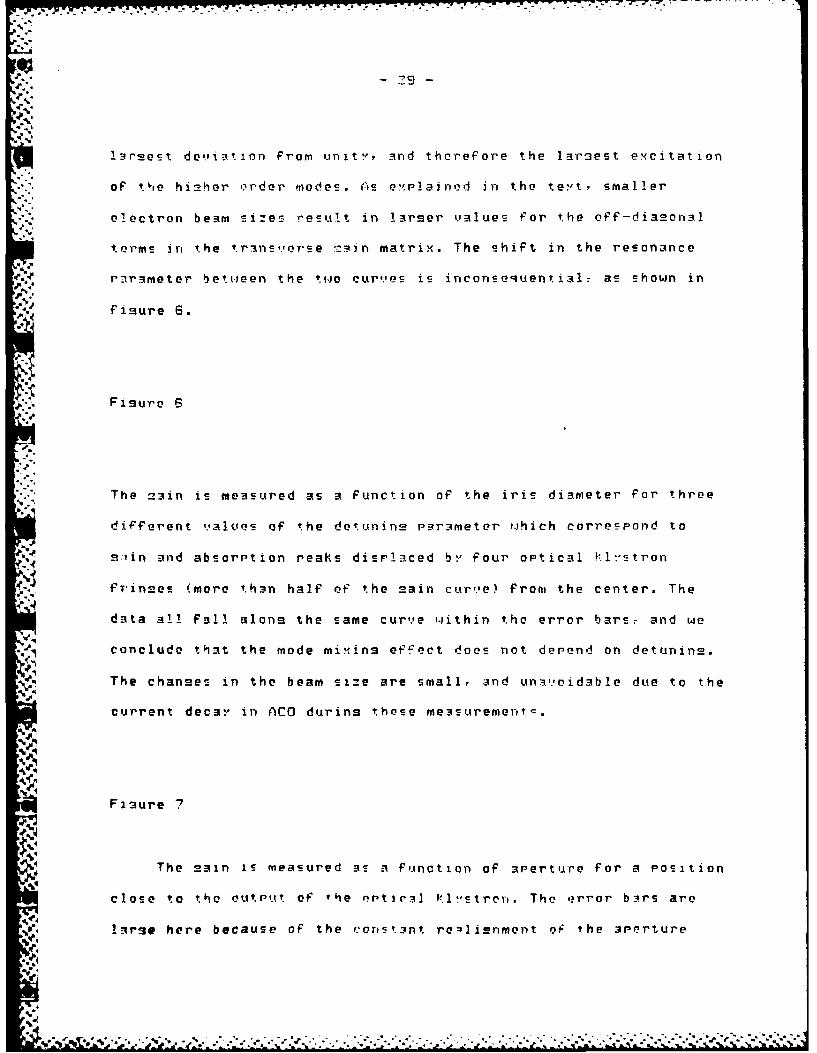
t - - ----
.,,-."
p..
-S.O
l-trsest de,.iation from unit-,, and therefore the larest excitation
of Pie hi_2her order modes. (is e';Plained in the teyt, smaller
electron beam sizes result in larser values for the off-diaeonl
terms n the trans,.'erse Tan matrix. The shift in the resonance
rarameter between the two cur,.,es is inconsequential. as shown in
Fisure 6
1
d".i The =3in is. meas.ured as a function of the iris diameter for three
I.
diFferent ,.,alues- of the detunin_ Paraimeter ,. ich corres pond to
~ s-l.in and absorption Peaks displaced b-" four optical k.l:' tron
e.J ~fr'innes (more th~n half of" the _2ain cur,.,e) from the center. The
data all fal! alons the s.ame cur,,e wJithin the error bars.= and we
,. conclude that the mode mi:.ing ef 'ect does_ not depend on detunins.
"w" The chanmes in the beam size are small, and un-i,.,oidable due to the
current decay in ACO durins these mea24Surement5.
Figure 7
The Tain is measured as a function Of aperture for a Poition
clo e to the outPef of the optc Pramstrer. The error bors are
farnse here becaue of the eoris nt relienment oF the perture
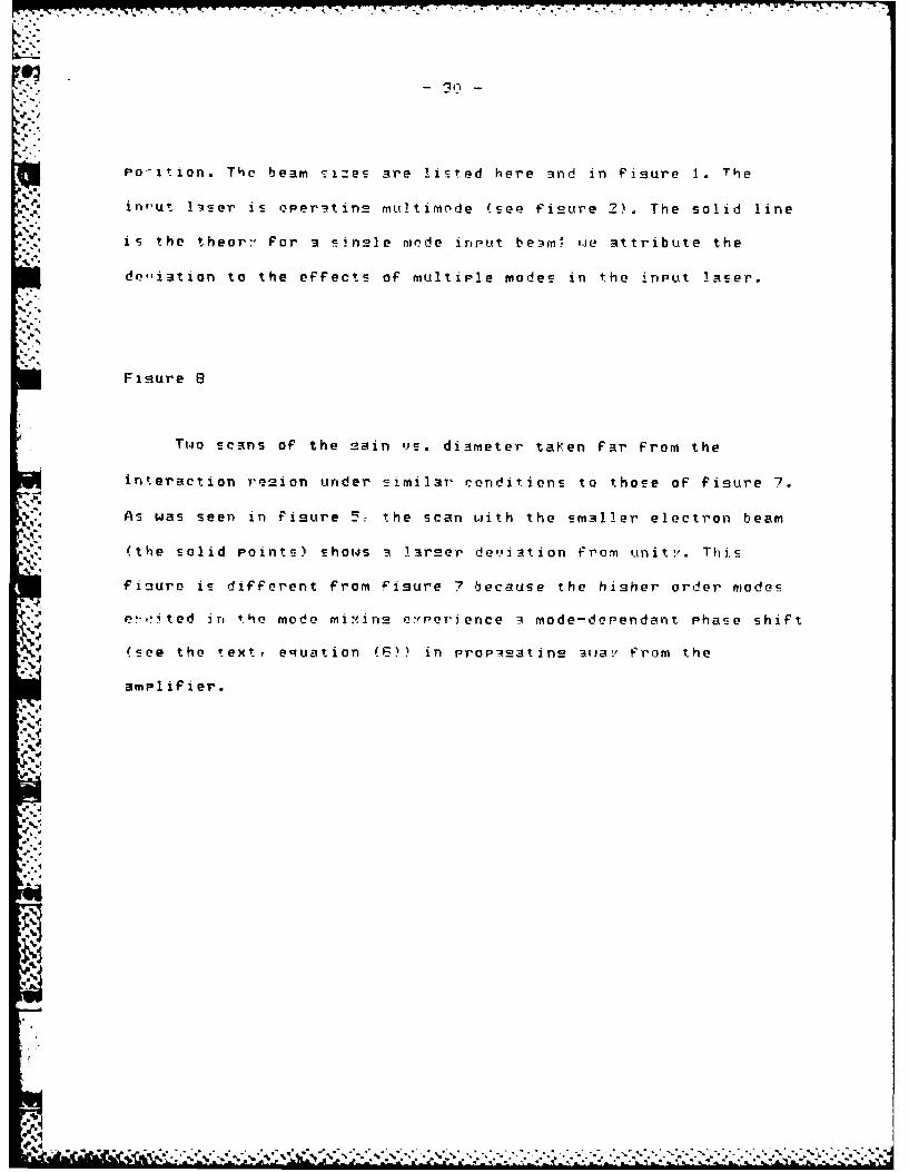
L.., - 30-
Po--ition. The beam sizes are listed here and in Figure 1. The
inrut 135er is oPeritin_ multimode (see Fisure 2). The solid line
is the theor- For a sinsle mode input beam" we attribute the
de,,iation to the effects of multiple modes in the input laser.
JJ Fisure 8
Tw.o scans of the m-ain 1v1. diameter taKen fair from the
j interaction re~ion under similar conditions to those of fisure 7.
" As was seen in Figure 57 the scan with the smaller electron beam
, (the solid Points) showcs i lar__er de,.,i-_Ation from unit-,. This
~fisure is different from fisure 7 because the hisher order modes
" .P-,oted i-, tho mode mix.in-e e:,POTr ence -4 mode-derendant Phase shift
j (--ee the text, e qiuation (C-)) in prop-4_aatin __ _ :,from the
amplifier.
4'4 *4
4. .°
Fisure
I " ", .', " "- . " ", Two-" -- sc n-f h am i'-da e e ta"• en" far ". from . ,'. the.'""''""""-" . '''.''' '
in ' teact ion .- --- re - 's under•, '-. -similar.. conditions to..... those of f-iure 7-.- °, -,., .,

0 0.
C 0
0 0
0 C 0+d
000
0 < z0 D
2 <2LLJ 0
0
-- p-
LL00- L 4
IC)
4(W

. oa-a
II| /
IN mom
oi,,
-Sdj
-4o
.ta
1w
, N i~ l l
,- J Pll> .. il 2
'4 iS -mmn
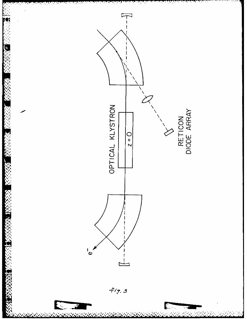
*0 p
U)c 0<
-J 0
U
C-7-

GAIN SERIES I
GAIN(iris open) z 14.3mW= 3.2mm
1.5
.,° .
0.5
mode
-.--. ' * ,5 -
....
*4_4-..
Iris diameter~Wlz)
SI I II
1 2 3 4 17
J',2
(,?°
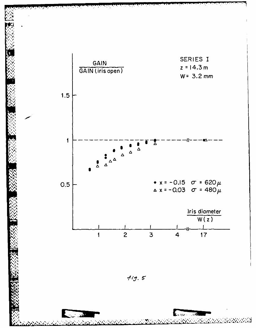
SERIES I-. GAIN
GI-.spnz = 14.3m~W = 3.2 mm.--,GAIN (iris open) W =}.
1.5
1~ = -0.0 - = -48- -* "- * A
"4- *4
i 0.5 • x---0.15 o- 62O/.
,,x--.03 o 4 8 0.t
Iris diameterW(z)
1I 3 4 11 2 3 4 17
4"..
'9: : ,. ,
€ ,U..."....... ..%J........
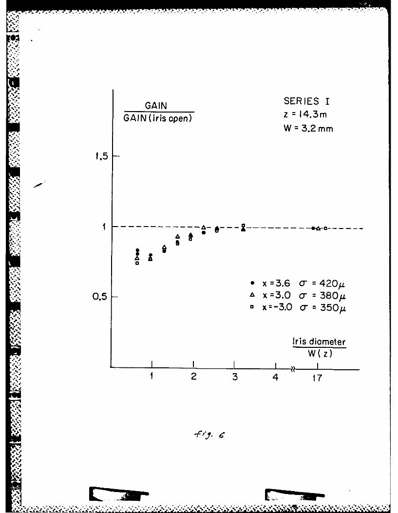
GAIN SERIES I"; z =14.3m-. :'2: G A I N (iris open)
W 3.2mm
1.5
.
"S
- - - - - - - - - - - - -- -
A
,~~~ 3, . ,x :.6 ":420,u'--',:0.5 - x x=3.0 o"=380,u
"x=-3.0 o-:350/1
Iris diameterW(z)
::;I2 3 4 17AAl
" '.9O..- ',ti

GAIN SERIES IGAIN (iris open) z = 2.88mW= 1.4mm
.1.
1.5-
AW W
0.5 A -H 450 V 31 0 /
*0 cOH :3 4 0 o-v :290J.
Iris diameter++-: W(z)
I I I I I1 2 ,3 4 17
9!
II
: + +I, . :.i T
-" • " I ,, '+ +. + " .+ + " " .+" + " *'*- ,*: , , . ,

- .ft .. .! P . ,
I "*
GAIN SERIES H' z 14.3m
GAIN(iris open) W6.2mm
1.5
NL ' 0
0.5 - OH - 3 6 0 ov = 33 0LO"H o- v 4 2 0/
Iris diameterW(z)
I I I1 2 3 4 17
-Low