loheeeei - dtic
TRANSCRIPT
AD-R148 836 B1-PAC F-:15 EXTERNAL FUEL TANK CONTAINER MODIFICATION i/i(U) AIR FORCE PACKAGING EVALUATION AGENCYWRIGHT-PATTERSON AFB OH E J KOWALSKI SEP 84
UNCLASSIFIED PTPD-84-R-2 F/G 03/4 N
LohEEEEI
.1.8
111.4 1 13 6! IIII II~l III'.
MICROCOPY RESOLUTION TEST CHARTNATIONAL FJREAU OF STANDARDS 1963 A
.
',=
.4
a
4°
q.
I
*-.. "., .,-"* ," w . % ."Y' ' '..4 r ",= '4 .**..',.*4*54 5 ,* .- ' w.. = ".~ t- W" V %' ,LW, V , %' ,, - ~
I/
APPROVED FOR PUBLIC RELEASE (3 PTPD IPORT NO. 84-R-02DISTRIBUTION UNLIPITED FTP ROJRCT no. 84-.i I
AD NO. 538026
00
fl EDWARD J. KOAUlKI
Mechanical Engineer
AUTOVON 787-3120
Coswercial (513) 257-3120
Q. BI-PAC F-15 EXTERNAL FUEL TANK CONTAINER MODIFICATIONCD
LQ~
HQ AFLC/DSTZ DTICAIR FORCE PACKAGING EVALUATION AGENCY ELECTE
Wright-Patterson AFB OR 13 DEC96
September 1984S
84 12 13 016
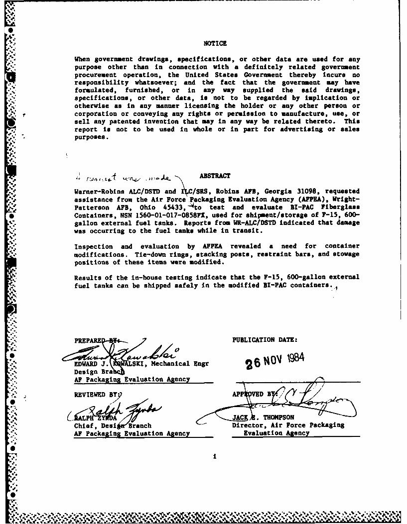
NOTICE
When government drawings, specifications, or other data are used for any
purpose other than in connection with a definitely related governmentprocurement operation, the United States Government thereby incurs noresponsibility whatsoever; and the fact that the government may haveformulated, furnished, or in any way supplied the said drawings,specifications, or other data, is not to be regarded by implication orotherwise as in any manner licensing the holder or any other person or
N. corporation or conveying any rights or permission to manufacture, use, orsell any patented invention that may in any way be related thereto. This
report is not to be used in whole or in part for advertising or salespurposes.
.;*
". r~c ~ABSTRACT
Warner-Robins ALC/DSTD and /CISRS, Robins AFB, Georgia 31098, requested. assistance from the Air Force Packaging Evaluation Agency (AFPHA), Wright-
Patterson AFB, Ohio 45433, 4to test and evaluate BI-PAC Fiberglass* Containers, NSN 1560-01-017-0858FX, used for shipment/storage of F-15, 600-
gallon external fuel tanks. Reports from WR-ALC/DSTD indicated that damagewas occurring to the fuel tanks while in transit.
Inspection and evaluation by AFPEA revealed a need for container
modifications. Tie-down rings, stacking posts, restraint bars, and stowagepositions of these items were modified.
Results of the in-house testing indicate that the F-15, 600-gallon externalfuel tanks can be shipped safely in the modified BI-PAC containers.
9o.
PREPAREn- PUBLICATION DATE:
EDAR ega SKI, Mechanical Engr26 I''~Design Brah
AF Packaging Evaluation Agency
REVIEWED BY: APP VED B
JAC THOMPSONChief, Desi Branch Director, Air Force PackagingAF Packaging Evaluation Agency Evaluation Agency
TABLE OF CONTENTS
PAGE
ABSTRACT .. . . . . . . . . . . . . . . . . . . . . . . . . . . .
TABLE OF CONTENTS.................................................jjt
INTRODUCTION......................................................1I
BACKGROUND........................................................ 1
PURPOSE...................................................... 1
TEST SPECIMENS.................................................... 1
TEST OUTLINE AND TEST EQUIPMENT .................................... 2
TEST PROCEDURES AND RESULTS ........................................ 2
TETN.lPNUU-MAT................0
TEST NO. le(RET, PENDULUACT...............................2
TEST NO. la, (REA) EDULUM-OTINACT.........................
%.TEST NO. lb, CEDNEWISE-DROP (ROTATIONAL)..................... 3
TEST NO. 2b, EVISEDP(OATIONA ).......................... 3
TEST NO. 2b, VIBRATION ...........o.............................3
TEST No. 3, TIE-DOWN STRENGTH ................................ 4
4CONCLUSION ....................................................... 4
RECOMMENDATION.................................................... 4
TABLE I, CONTAINER TEST PLAN ....................................... 5
FIGURE 1, BI-PAC CONTAINER, NSN 1560-01-017-0858FX ................. 6K ~ ~~~FIGURE 2, CONTAINER DAMAGE, SIDE VIEW ........................................ 6
FIGURE 3, STRAP DAMAGE .................................. 6
FIUR 4, FUEL TANK ROTATION .................................................... 7
FIGURE 5, LOOSE STRAP, CORNER POST ................................. 7
WA .WWV.6.%
ydH

FIGURE 6, LOOSE STRAP, FUEL TANK FORWARD END ........... 7
FIGURE 7, LOOSE ANGLE IRON, FORKLIFT ENTRY ............ 8
FIGURE 8, TIE-DOWN RING INSTALLATION ............... 8
FIGURE 9, BACK-UP PLATE, TIE-DOWN RING INSTALLATION ........ B
FIGURE 10, TIE-DOWN RING CLEARANCE, CONTAINER STACKING .............. 9
FIGURE 11, STACKING POST MODIFICATION ........................ 9
FIGURE 12, STACKING POST, INSTALLED ................................ 9
FIGURE 13, STACKING POST BRACKET INSTALLATION, STOWAGE POSITION .. 10
FIGURE 14, STACKING POST IN STOWAGE POSITION,4GUIDE PIN ASSEMBLY ............................................ 10
FIGURE 15, STACKING POST METAL STRAP MODIFICATION ................... 10
FIGURE 16, STACKING POST IN STOWAGE POSITION ....................... 11
FIGURE 17, STACKING POST IN STOWAGE POSITION,NYLON STRAP MODIFICATION ...................................... 11
FIGURE 18, RESTRAINT BAR MODIFICATION .............................. 11
FIGURE 19, RESTRAINT BAR MODIFICATION .............................. 12
FIGURE 20, BACK-UP PLATE, RESTRAINT BAR INSTALLATION ................ 12
FIGURE 21, RESTRAINT BAR END ....................................... 12
FIGURE 22, RESTRAINT BAR, FUEL TANK MOUNTING LUG .................... 13
FIUE2,RSTAN.ASTWG..IIN............. 1
FIGURE 23, RESTRAINT BAR, STOWAGE POSITION ......................... 13
FIGURE 24, VRTINTEBRSTOWAGE.POSITIO...................... 13
0FIGURE 25, VIBRATION TEST,..........................................14
FIGURE 27,VBACONT E AMG, SACED.................................14
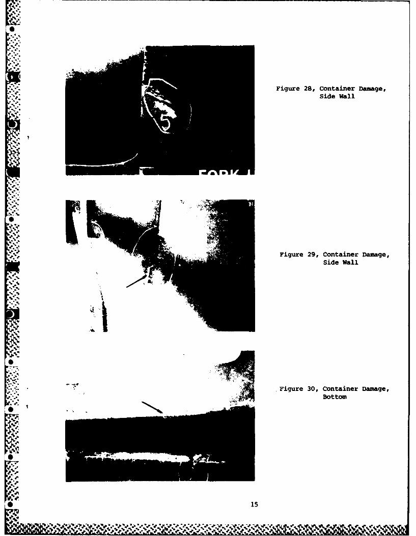
FIGURE 27, CONTAINER DAMAGE, SIDE WALL ............................. 14
* 'FIGURE 28, CONTAINER DAMAGE, SIDE WALL ..............................1
- yN - N
FIGURE 30, CONTAINER DAMAGE, BOTTOK .............................. 15
FIGURE 31, TIE-DOWN RING TEST .......................... ...... * 16
FIGURE 32, TIE-DOWN RING TEST A...LL UU.......................... 16
F IGU 33, TIE-DOWN RIN,. SIDE WALL RUFR .. o........o........ 16
FIGURE 34, TIE-DOWN RING, SIE WALL RUFTURE ............. 7.......17
FIGRE 35, MA&lNG DIAGRAM ..o ... ............... .......... ... 18
DISTRIBUTION LIST .... ................ 19
-iPA C sc I onI For
.AA
• ."!Dla .i or
,d"
*58 ."
.'
.J.°
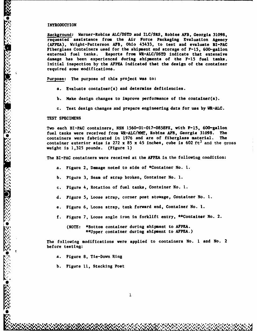
A. INTRODUCTION
,- Background: Warner-Robins ALC/DSTD and ILC/SRS, Robins AFB, Georgia 31098,requested assistance from the Air Force Packaging Evaluation Agency(AFPEA), Wright-Patterson AFB, Ohio 45433, to test and evaluate BI-PACFiberglass Containers used for the shipment and storage of F-15, 600-gallonexternal fuel tanks. Reports from WR-ALC/DSTD indicate that extensivedamage has been experienced during shipments of the F-15 fuel tanks.Initial inspection by the AFPEA indicated that the design of the containerrequired some modifications.
Purpose: The purpose of this project was to:
a. Evaluate container(s) and determine deficiencies.
b. Make design changes to improve performance of the container(s).
c. Test design changes and prepare engineering data for use by WR-ALC.
TEST SPECIMENS
4. Two each BI-PAC containers, NSN 1560-01-017-0858FX, with F-15, 600-gallonfuel tanks were received from WR-ALC/MNT, Robins AFB, Georgia 31098. The
0 containers were fabricated in 1976 and are of fiberglass material. Thecontainer exterior size is 272 x 85 x 45 inches, cube is 602 ft3 and the grossweight is 1,325 pounds. (Figure 1)
The BI-PAC containers were received at the AFPEA in the following condition:
a. Figure 2, Damage noted to side of *Container No. 1.
b. Figure 3, Seam of strap broken, Container No. 1.
c. Figure 4, Rotation of fuel tanks, Container No. 1.
d. Figure 5, Loose strap, corner post stowage, Container No. 1.
e. Figure 6, Loose strap, tank forward end, Container No. 1.
f. Figure 7, Loose angle iron in forklift entry, **Container No. 2.
(NOTE: *Bottom container during shipment to AFPEA.**Upper container during shipment to AFPEA.)
The following modifications were applied to containers No. 1 and No. 2before testing:
7 a. Figure 8, Tie-Down Ring
b. Figure 11, Stacking Post
A':
0c. Figure 16, Stacking Post In Stowage Positiond. Figure 17, Stacking Post in Stowage Position
e. Figure 18, Restraint Bar
f. Figure 24, Restraint Bar in Stowage Position-A
-. g. Figure 35, Marking Diagram
'V Two sets of restraint bars were fabricated. One set of restraint bars wasfabricated from one-inch x 0.125 wall square structural steel tube and one
set of restraint bars was fabricated from l%-inch x 0.188 wall squarestructural steel tube.
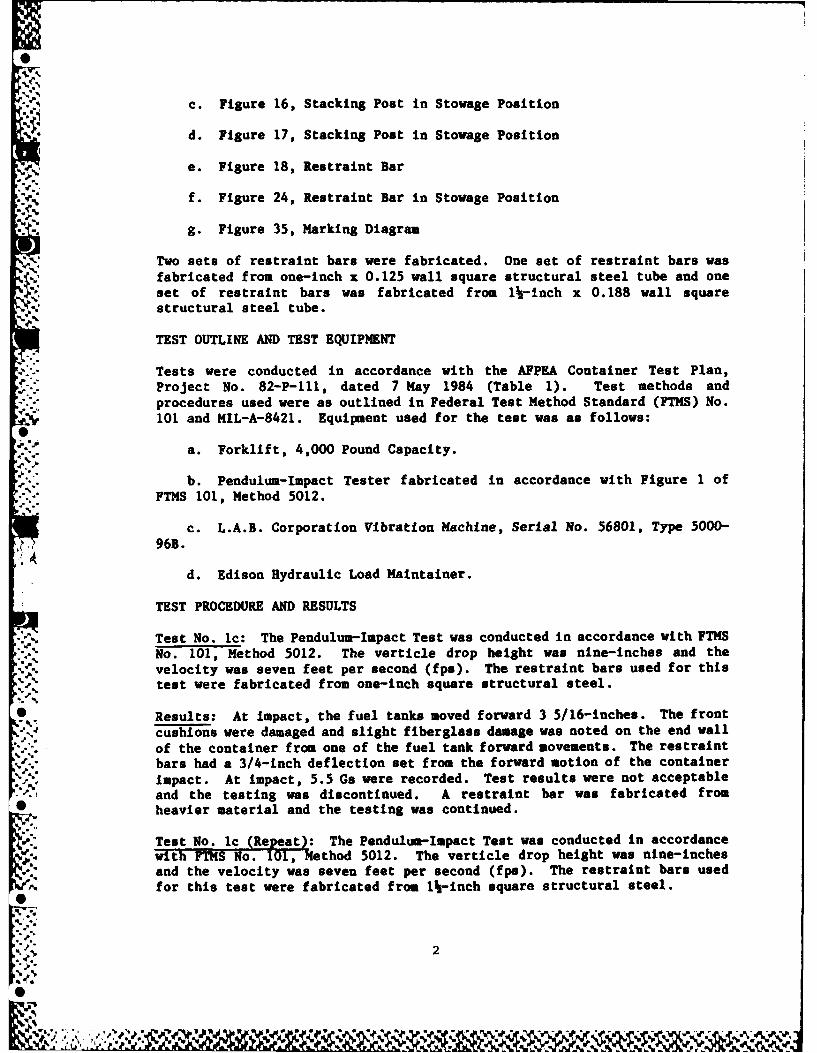
TEST OUTLINE AND TEST EQUIPMENT
Tests were conducted in accordance with the AFPEA Container Test Plan,Project No. 82-P-111, dated 7 May 1984 (Table 1). Test methods and
-. procedures used were as outlined in Federal Test Method Standard (FTMS) No.101 and MIL-A-8421. Equipment used for the test was as follows:
a. Forklift, 4,000 Pound Capacity.
b. Pendulum-Impact Tester fabricated in accordance with Figure 1 ofFTMS 101, Method 5012.
c. L.A.B. Corporation Vibration Machine, Serial No. 56801, Type 5000-
96B.
d. Edison Hydraulic Load Maintainer.
TEST PROCEDURE AND RESULTS
Test No. 1c: The Pendulum-Impact Test was conducted in accordance with FTMSNo. 101, Method 5012. The verticle drop height was nine-inches and thevelocity was seven feet per second (fps). The restraint bars used for thistest were fabricated from one-inch square structural steel.
* Results: At impact, the fuel tanks moved forward 3 5/16-inches. The front
cushions were damaged and slight fiberglass damage was noted on the end wall, of the container from one of the fuel tank forward movements. The restraint
bars had a 3/4-inch deflection set from the forward motion of the container
impact. At impact, 5.5 Gs were recorded. Test results were not acceptableand the testing was discontinued. A restraint bar was fabricated from
• heavier material and the testing was continued.
Test No. 1c (Repeat): The Pendulum-Impact Test was conducted in accordancewith FThS No. 101, Method 5012. The verticle drop height was nine-inchesand the velocity was seven feet per second (fps). The restraint bars usedfor this test were fabricated from 1%-inch square structural steel.
2
S

Results: At impact, the fuel tanks moved forward 1 3/8-inches. Both endcushions were crushed slightly from the forward Impact of the containers.At impact, 6.5 Gs were recorded. After the test, no visual damage was notedto the fuel tanks, the container, or to the container modifications. Testresults were acceptable and the testing was continued.
Test No. la: The Cornerwise-Drop (Rotational) Test was conducted inaccordance with FTMS No. 101, Method 5005. 1. The height of the drop was 15inches.
Results: On the second Cornervise-Drop (Rotational) Test, damage occurredto the corner stacking post. One end of the corner post was sheared and the
-: corner post fell on top of the fuel tank. No damage occurred to the fueltank. The stacking posts were modified and testing was continued (Figure 11 and12). Visual inspection after the 3rd and 4th cornerwise drops (rotational)revealed no damage to the fuel tanks, the container, or the container modi-fications. Results of the tests were acceptable.
Test No. 1b: The Edgewise-Drop (Rotational) Test was conducted in
accordance with FTMS No. 101, Method 5008.1. The height of the drop was 15Inches.
* Results: Visual inspection, after the test, revealed no physical damage tothe fuel tanks, the container, or to the container modifications. Resultsof the tests were acceptable.
-~ Test No. 2a: The Vibration Test was conducted in accordance with FTMS No.101, Method 5019.1. The container was placed on a vibration table andvibrated for two hours at 3.6 Hz, 1.0 G (Figure 25).
Results: Visual inspection, after the test, revealed no physical damage tothe fuel tanks, the container, or the container modifications. Results ofthe tests were acceptable.
Test No. 2b: The Vibration Test was conducted in accordance with FTMS No.
101, Method 5019.1. The containers were stacked (two high), placed on avibration table, and vibrated for two hours at 3.8 Hz, 1.0 G (Figure 26).Note container strapping, straps approximately 20-inches from the containerends and also at the center of balance. Straps were used during the testfor the safety of personnel and container balance and not to simulate tie-down conditions during transit.
Results: Visual inspection, after the test, revealed no physical damage tothe fuel tanks or to the container modifications. However, damage was notedto the fiberglass containers (Figures 27, 28, 29, and 30). Damage to theside walls, ends, and bottoms of the containers are an extension of damageon the units as received from the field. Environmental conditions, becauseof outdoor storage as well as container wracking when in transit, arecontributing factors in the rupture of the fiberglass materials. Results ofthe tests were acceptable.
0
Ew3
0e
fbkA - 0%..f .0 N' V~' .* %, %I *%"%m %,% %C.A4?'. . . . .A.

Test No. 3: The Tie-Down Strength Test was conducted in accordance withMIL-STD-648, paragraph 5.8.4, and MIL-A-8421, paragraph 3.3.4. A 6,000
pound maximum load was required for the Tle-Down Strength Test (Figure 31and 32).
Results: Visual inspection of the tie-down rings and the container sidewalls revealed no damage at the 6,000 pound loading. However, the test was
continued until the side wall of one of the modified tie-down rings ruptured
(Figure 34). A test load of 14,700 pounds was applied to the tie-down ringsbefore the side wall ruptured. Results of the test were acceptable.
CONCLUSION
In-house testing of the modifications applied to the containers fabricatedin 1976 indicate that the F-15, 600-gallon fuel tanks can be shipped safelyin these modified containers. Caution should, however, be exercised in the
selection of the BI-PAC Container, NSN 1560-01-017-0858FX, before themodifications are applied. All BI-PAC containers should be inspected forstress cracks and/or other damage and should be repaired only if material and
labor cost are within the specified limits of the initial container cost.*" No modifications should be applied to unserviceable containers.
RECOMMENDATION
Stress cracks should be repaired or they will continue to propagate and thuscause additional damage to the BI-PAC containers. The stress cracks may
weaken the walls, ends, or bottom to a point where they may collapse and
cause damage to the fuel tanks.
It is also recommended that shipment(s) of BI-PAC container(s), with fueltanks, be made on flat-bed trailers that will fully support the 272-inch
length and the 85-inch width of the container(s). No overhang of the
container(s) should be permitted because the design of the container(s)requires a full support of the base. Any amount of overhang on the trailerwill cause container(s) flexing and lead to a possible collapse of the sidewalls.
Container markings should be stenciled on both sides of the container as an
* attention notification to the transporter (Figure 35).
4
Sk
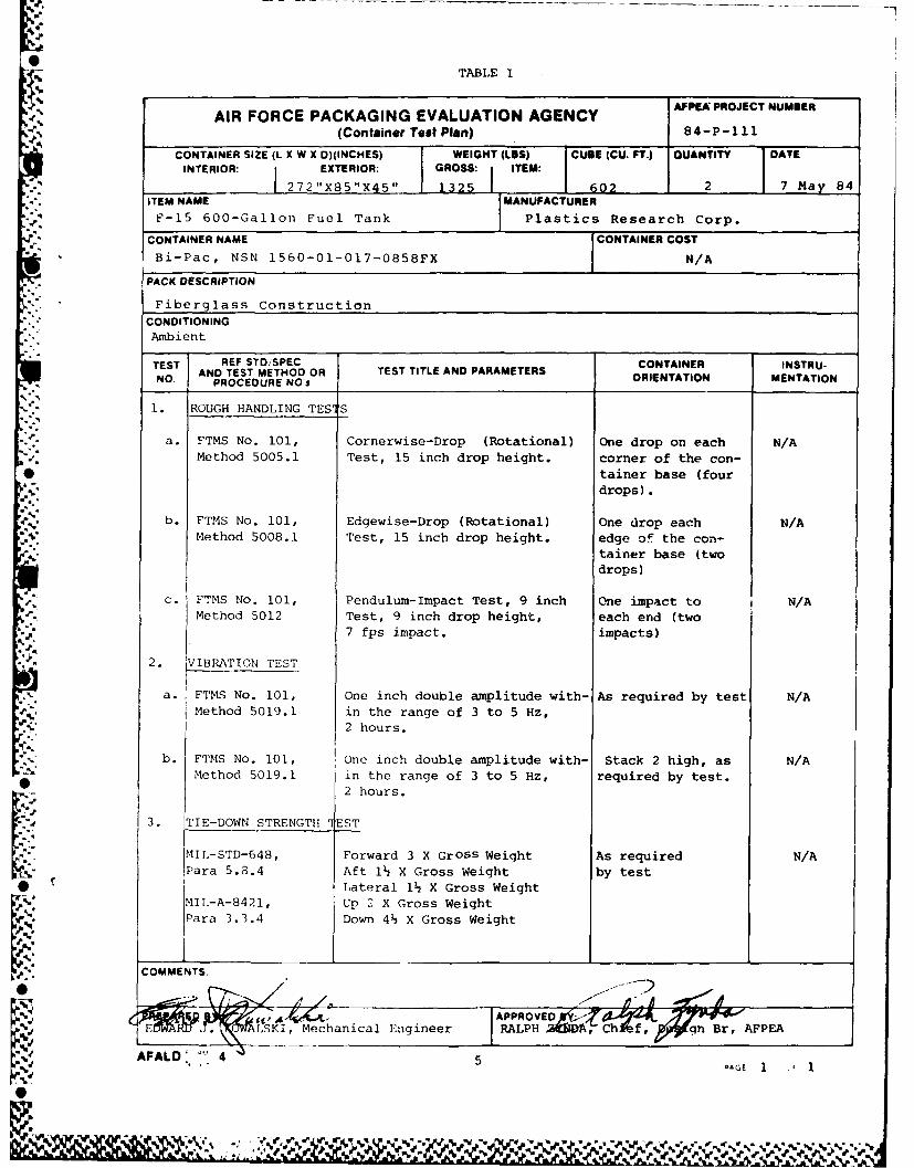
TABLE I
AIR FORCE PACKAGING EVALUATION AGENCY AFPEX PROJECT NUMBER
A (Container Test Plan) 84-P-111
CONTAINER SIZE (L X W X D)(INCHES) WEIGHT (LBS) CUBE (CU. FT.) OUANTITY DATEINTERIOR: EXTERIOR: GROSS- ITEM
1 272"X85"X45" 132M 602 2 7 Mav 84ITEM NAME MANUFACTURERF-15 600-Gallon Fuel Tank Plastics Research Corp.
CONTAINER NAME CONTAINER COSTBi-Pac, NSN 1560-01-017-0858FX N/A
PACK DESCRIPTION
Fiberglass Construction
CONDITIONINGAmbient
TEST REF STDSPEC CONTAINER INSTRU-NO. AND TEST METHOD OR TEST TITLE AND PARAMETERS ONTAIN MNTRTON. PROCEDURE NO's ORIENTATION MENTATION
1. ROUGH HANDLING TESqS
a. FTMS No. 101, Cornerwise-Drop (Rotational) One drop on each N/AMethod 5005.1 Test, 15 inch drop height. corner of the con-
* tainer base (fourdrops).
b. FTMS No. 101, Edgewise-Drop (Rotational) One drop each N/AMethod 5008.1 Test, 15 inch drop height. edge of the con-
tainer base (twodrops)
c. FTMS No. 101, Pendulum-Impact Test, 9 inch One impact to N/AMethod 5012 Test, 9 inch drop height, each end (two
7 fps impact, impacts)
2. VIBRATION TEST
a. FTMS No. 101, One inch double amplitude with- As required by test N/AMethod 5019.1 in the range of 3 to 5 Hz,
2 hours.
b. FTMS No. 101, One inch double amplitude with- Stack 2 high, as N/AMethod 5019.1 in the range of 3 to 5 Hz, required by test.
2 hours.
3. TIE-DOWN STRENGTH JEST
MIL-STD-648, Forward 3 X GrOSs Weight As required N/APara 5.3.4 Aft 1 X Gross Weight by test
* rLateral 1 X Gross WeightMIL-A-8421, Up 2 X Gross WeightPara 3.3.4 Down 4 X Gross Weight
L-,'.'.COMMENTS.
Fji E-AI . ALSKI , Mechanical Engineer RALPH Zfb ATChJ~fv .7BrLFPEA
AFALD. 4-,1.- 5 -AGE
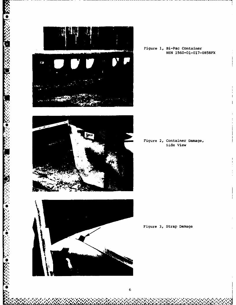
Figure 1, Bi-Pac ContainerNSN 1560-01-017-0858FX
Figure 2, Container Damage,Side View
-V Figure 3, Strap Damage
06
0ZrNo
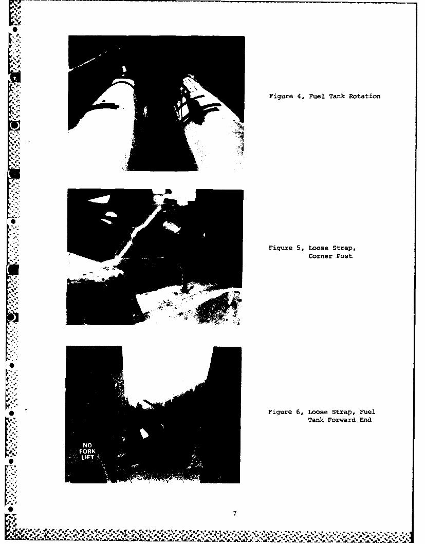
Figure 4, Fuel Tank Rotation
Figure 5, Loose Strap,
Corner Post
Figure 6, Loose Strap, FuelTank Forward End
tNIFORK1aW
* 47
NI%

Figure 7, Loose Angle Iron,Forklift Entry
Figure 8, Tie-Down Ringi Installation
Figure 9, Back-Up Plate, Tie-Down Ring Installation
js. 8
%%% V V %

Figure 10, Tie-Down RingClearance, ContainerStacking
Figure 11, Stacking PostModification
Figure 12, Stacking PostInstalled
S9

Figure 13, Stacking PostBracket InstallationStowage Position
Figure 14, Stacking Post inStowage Position,Guide Pin Assembly
Figure 15, Stacking Post MetalStrap Modification
* 1'
'p.:M wd-.6 2- -M6 MI I N .
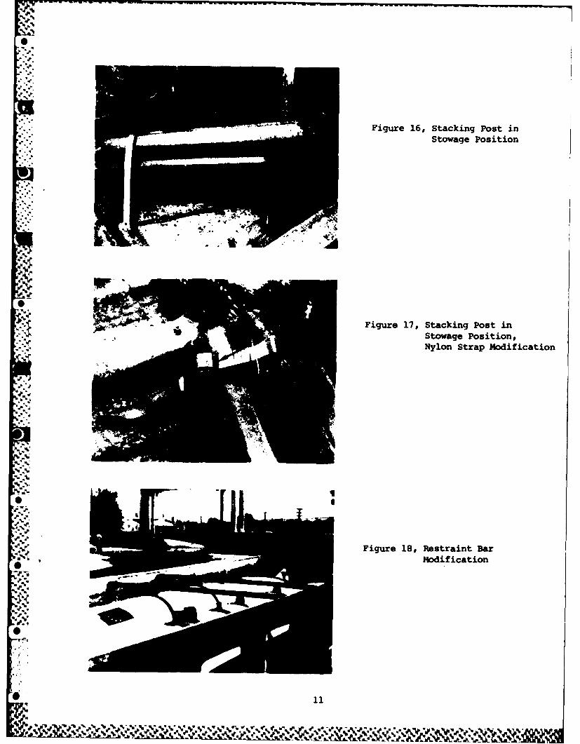
Figure 16, Stacking Post inStowage Position
Figure 17, Stacking Post in. .Stowage Position,
Nylon Strap Modification
Jo
.°7.
-
-'.4%%
, a-
,-"
V'. ,V," ,,, .,, inFigure 18, Restraint Bar- Modification
[O'
* 11-. o,, " f
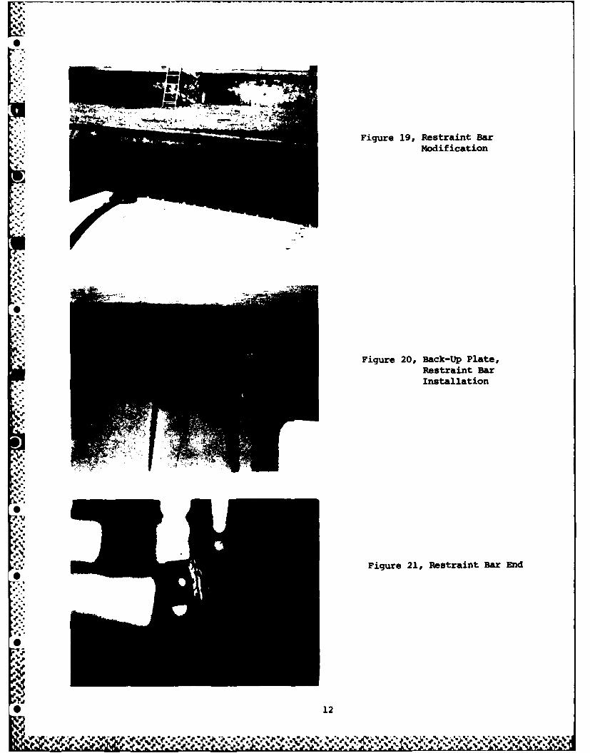
Figure 19, Restraint Bar
Modification
Figure 20, Back-Up Plate,Restraint BarInstallation
Figure 21, Restraint Bar End
* 12

Figure 22, Restraint Bar,Fuel Tank Mounting Lug
Figure 23, Restraint Bar,Stowage Position
Figure 24, Restraint Bar,
Stowage Position
* 13

Figure 25, Vibration Test
Figure 26, Vibration Test,Stacked
*i*14
**I? .e5-r10..
5-ISide Wall%
S: .
-'' Figure 28, Container Damage,::;, "Side Wall
S2.
..
Side Wall
.5k
.1 Figure 29, Container Damage,
• -.. _ . Bottom
Sieeal
Jo"
S
S15
% Se
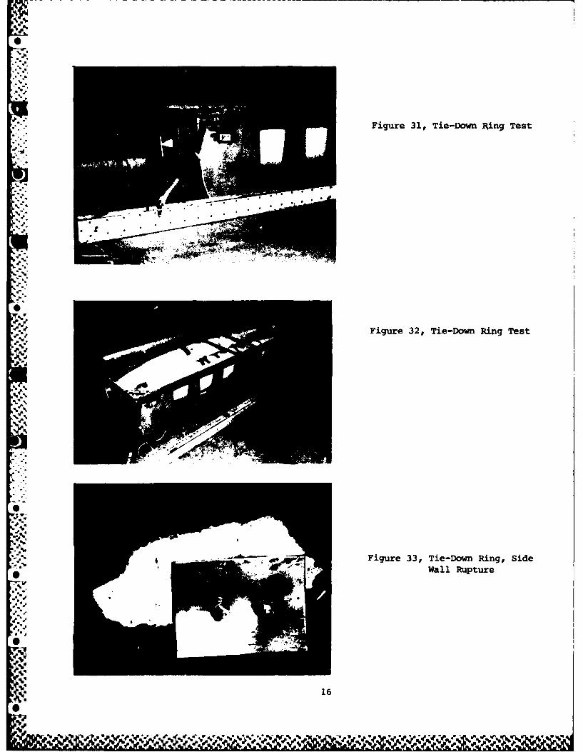
Figure 31, Tie-Down Ring Test
=..
Figure 32, Tie-Down Ring Test.1 -
'.-'
Figure 33, Tie-Down Ring, SideWall Rupture
P*d •
16
0
.4. N--I~ ~ %.,%ivr

0
.44...
4~~*
K
I'...
K
0
*1.Figure 34, Tie-Down Ring,
Side Wall Rupture
V.P
4.
.4
0
0
4....'
4..4
S. 4.
.4.
0
17
V. V.

00
z 3.
UU
o I4
0.0U
x .0U
w Vw
L)Lw1

DISTRIBUTION LIST
DTIC/TSR 12
* Cameron Station
Alexandria VA 22314
HQ AFLC/DSTZ Library 20
Wright-Patterson AFB OH 45433-5999
WR-ALC/DSTD 5
Robins AFB GA 31098-5999
W'R-ALC/MMT 2
Robins AFB GA 31098-5609
WR-ILC/SRA 2
Robins AFB GA 31098
HQ AFLC/DS 1
-. Wright-Patterson AFB OH 45433-5999
HQ USAF/LETT I
* Wash DC 20330
HQ AFLC/DSTP 1
.'.; Wright-Patterson AFB OH 45433-5999
OO-ALC/DST
Hill AFB UT 84406-5999
OC-ALC/DSTTinker AFB OK 73145-5999
SA-ALC/DST
Kelly AFB TX 78241-5999
WR-ALC/DSTRobins AFB GA 31098-5999
ASD/AWLWright-Patterson AFB OH 45433-6503
DLSIE/DRXMC-DUSA Logistics Management Center
Ft Lee VA 23801
* -% DARCOM/SDSTO-TTobyhanna PA 18466
US Army Natick Labs/DRDNA-EPS
Natick HA 01760
Z 19
U',
NAVSUPSYSCMD/SUP-0321AWash DC 20376
AD/YNPEglin AFB FL 32542
ASO/TEP-A 4030700 Robbins Avenue
* Philadelphia PA 19111
US Army Armament Research andDevelopment Center/SMCAR .- TST-S
Dover NJ 07801
GSA, Of c of Engrg MgmtPackaging DivisionWash DC 20406
HQ DLA-OWO
Cameron StationAlexandria VA 22314
0
02
ww .
% %
FILMED
185
, - ..~DTIC
w..
SlK ,'..-." _' , ,..e.,''' "" " "" " ° v., ,.. ., ,: ,'-".,,.,rv ,... -,%,:.,'', , ,", , :,. ,. ', / , :, . .,t.".,.,'-' # h., .. '- , .