scuttlebutt201 - 2009-12-04 - yccc · yccc scuttlebutt december 2009 page 1 scuttlebutt december...
TRANSCRIPT
YCCC Scuttlebutt December 2009 Page 1
Scuttlebutt December 2009 Issue 201
Next Meeting: Saturday December 12th, 2009 – 1PM to 5PM
Sturbridge Host Hotel, Sturbridge, MA
Captain’s Cabin
What a finish to the CQ WW for 2009! I heard a lot of YCCCers on the air running, S&Ping, busting pileups and just racking up the points and just having FUN! Thanks to all of you that put in the effort both within the territory as well as our DXpedition folks – job well done! Many personal bests, first time in the top ten for some, summer antenna projects REALLY paid off and the like!
The December meeting will be held on the 12th (Saturday) in Sturbridge. The same place as last time with that great theater style seating and can accommodate up to 125 people. Please come and enjoy some coffee and cake and share you recent CQ WW 2009 experiences. Lots of great stories to tell.
On the agenda, the officers are planning to conduct a round table discussion on the topic of the Strategy of Contest Station Design. We will have a range of speakers that will share with us the details behind their particular station design. The YCCC is growing and we have many new members that need to see what is possible – this round table discussion will help point the way. If you have a station with just wires, what can you really do? Are you planning (planting) a tower? What are you going to put on it to maximize the fun? Sure you can do that modeling but there is much more to it. There is an operating strategy to consider. Gain some insight for those that have been down many roads in an effort to gain a competitive advantage – we have an incredible resource in our midst and we plan to leverage it for your advantage.
Also we plan to have some DXpedition presentations – we had a number of YCCCers travel the world recently and these stories are always fun for us.
Although our scores collector, Dave, K1HT is still gathering the results from CQ WW, we will have some preliminary numbers to review – Have you seen the prelim results report on the 3830 reflector? Many YCCCers are in the top ten in many different categories and the scores – wow, huge numbers! Sunspots are making a comeback!
See you at the December meeting in Sturbridge on Saturday, December 12. Go YCCC and KB!
73, Mark, K1RX President, YCCC 2009-2010

YCCC Scuttlebutt December 2009 Page 2
Directions to Sturbridge Host Hotel Sturbridge Host Hotel & Conference Center is located on Route 20. - From the North, East and West, take the Massachusetts Turnpike (Interstate 90) to Exit 9, Route 20 West. - From the South, take either Interstate 84 or Route 131 to Route 20 West. Sturbridge Host Hotel & Conference Center is located on the shore of Cedar Lake, just past the first set of traffic lights.
Area Managers ME Mike Russo, K1EU (207) 883-9524 [email protected] ENH Glen Whitehouse, K1GW (603) 673-6290 [email protected] WNH/SVT Ed Sawyer, N1UR ------------------- [email protected] NE MA (978) Scott Andersen, NE1RD (978) 263-9617 [email protected] SE MA (508) Greg Cronin, W1KM (508) 428-4205 [email protected] Boston (617/781) Joe Fitzgerald, KM1P (617) 325-6767 [email protected] WMA (413) Tom Homewood, W1TO (413) 743-7342 [email protected] CT (860) Dick Pechie, KB1H ------------------- [email protected] CT (203) Dave Arruzza, W1CTN ------------------- [email protected] & Mike Loukides, W1JQ (203) 458-2545 [email protected] RI (401) OPEN ------------------- NNY John Bradke, W2GB ------------------- [email protected] NYC/LI (718) Tom Carrubba, KA2D (631) 422-9594 [email protected] SNY/NJ/PA (914) Hank Kiernan, KF2O (914) 235-4940 [email protected] NVT (802) Al Frugoli, KE1FO (802) 893-8388 [email protected]
Articles in the Scuttlebutt (except for those separately copyrighted) may be reprinted, provided proper credit is given.
The editorial deadline for the Scuttlebutt is the 10th of every odd month.
Yankee Clipper Contest Club President Mark Pride, K1RX (603) 778-1222 [email protected]
Vice President Richard Feola, W1STT [email protected] Activities Manager Mark Watson, W1MAW [email protected]
Secretary George Harlem, W1EBI [email protected] Treasurer Ed Parish, K1EP [email protected] Scuttlebutt Editor Steve Rodowicz, N1SR (413) 593-6554 [email protected] Scuttlebutt Publisher Ken Miller , WB1DX [email protected]
Webmaster Mike Gilmer. N2MG (315) 829-5291 [email protected] Scorekeeper Dave Hoaglin, K1HT (978) 443-3603 [email protected] W1 QSL Bureau Art Holmes, W1RZF Manager [email protected] Technical Assistance Dave Jordan, K1NQ Manager [email protected] New Members S. Khrystyne Keane, K1SFA Manager [email protected]
YCCC Scuttlebutt December 2009 Page 3
Flotsam & Jetsam Barnacle Jack (BJ) Schuster, W1WEF [email protected]
Ahoy Maties! Hope you had as much fun this contest season as I did! It’s not over yet…there’s still a contest every weekend. Les, N1SV did an interesting thing this year in his 30th year as a ham. He set a goal to operate in 30 contests! He’s got me thinking of trying the same idea next year…operate in 58 contests. I guess that might stop me from traveling at all though…
Brian, K1LI (aka Smokey Bear) sent this: I wanted to consolidate antennas around the tower in the North field to free up space in the South field for low-band antenna development. Adding a second "bent vertical dipole" (a "BVD" a la K2KQ's "double L") to the existing 160m BVD seemed like an easy way to replace the Gap Voyager DX. Unfortunately, I don't have a second tall support to allow me to space the legs of the 80m and 160m "elements" as Don recommends. Taking a cue from the old "fan dipole" concept, I simply constructed a pair of parallel BVDs using the plastic spacers left over from the rebuilds of three
KT34XAs to separate the wires by about six inches. It works better than the Gap and I didn't have to prune the wires at all from the lengths chosen through NEC2 modeling.
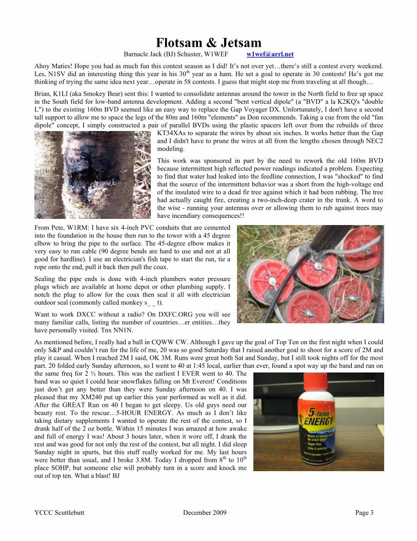
This work was sponsored in part by the need to rework the old 160m BVD because intermittent high reflected power readings indicated a problem. Expecting to find that water had leaked into the feedline connection, I was "shocked" to find that the source of the intermittent behavior was a short from the high-voltage end of the insulated wire to a dead fir tree against which it had been rubbing. The tree had actually caught fire, creating a two-inch-deep crater in the trunk. A word to the wise - running your antennas over or allowing them to rub against trees may have incendiary consequences!!
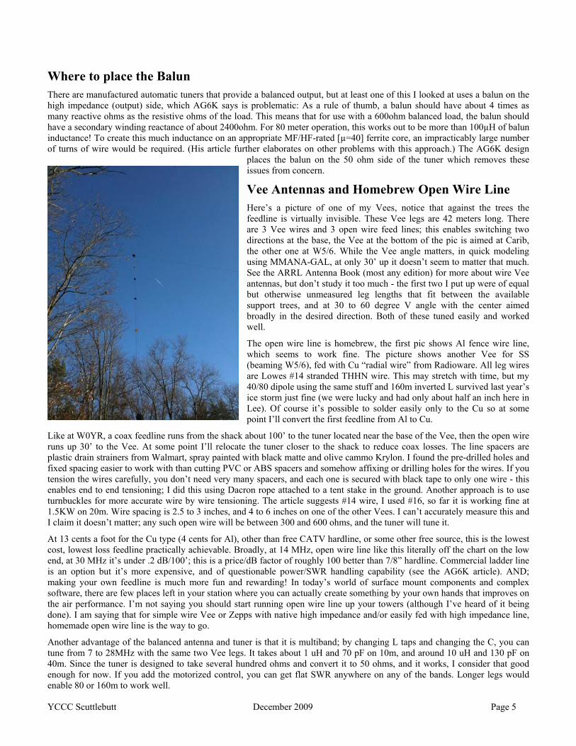
From Pete, W1RM: I have six 4-inch PVC conduits that are cemented into the foundation in the house then run to the tower with a 45 degree elbow to bring the pipe to the surface. The 45-degree elbow makes it very easy to run cable (90 degree bends are hard to use and not at all good for hardline). I use an electrician's fish tape to start the run, tie a rope onto the end, pull it back then pull the coax.
Sealing the pipe ends is done with 4-inch plumbers water pressure plugs which are available at home depot or other plumbing supply. I notch the plug to allow for the coax then seal it all with electrician outdoor seal (commonly called monkey s_ _ t).
Want to work DXCC without a radio? On DXFC.ORG you will see many familiar calls, listing the number of countries…er entities…they have personally visited. Tnx NN1N.
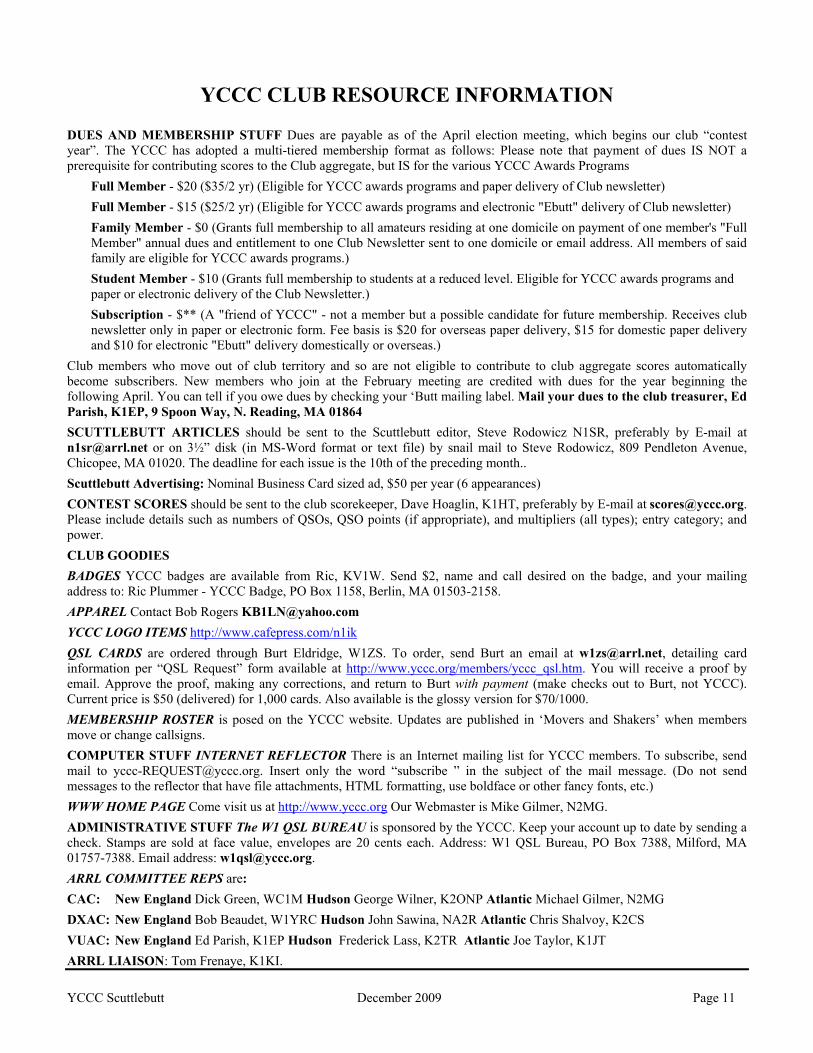
As mentioned before, I really had a ball in CQWW CW. Although I gave up the goal of Top Ten on the first night when I could only S&P and couldn’t run for the life of me, 20 was so good Saturday that I raised another goal to shoot for a score of 2M and play it casual. When I reached 2M I said, OK 3M. Runs were great both Sat and Sunday, but I still took nights off for the most part. 20 folded early Sunday afternoon, so I went to 40 at 1:45 local, earlier than ever, found a spot way up the band and ran on the same freq for 2 ½ hours. This was the earliest I EVER went to 40. The band was so quiet I could hear snowflakes falling on Mt Everest! Conditions just don’t get any better than they were Sunday afternoon on 40. I was pleased that my XM240 put up earlier this year performed as well as it did. After the GREAT Run on 40 I began to get sleepy. Us old guys need our beauty rest. To the rescue…5-HOUR ENERGY. As much as I don’t like taking dietary supplements I wanted to operate the rest of the contest, so I drank half of the 2 oz bottle. Within 15 minutes I was amazed at how awake and full of energy I was! About 3 hours later, when it wore off, I drank the rest and was good for not only the rest of the contest, but all night. I did sleep Sunday night in spurts, but this stuff really worked for me. My last hours were better than usual, and I broke 3.8M. Today I dropped from 8th to 10th place SOHP, but someone else will probably turn in a score and knock me out of top ten. What a blast! BJ

YCCC Scuttlebutt December 2009 Page 4
Wire antenna enthusiasts: Try a Balanced Antenna Tuner with a multi-band Vee beam or Zepp
Tom Poland – N9NC
Introduction and Motivation A few weeks ago, in preparation for Sweepstakes, I stumbled on to the idea to try a Vee beam with open wire feedline. Last year I tried an OWA wire yagi for 40m and 20m – it worked OK, but dimensions were critical, it was relatively narrowband - it turned out trying to do 2 bands on the same rope boom made the typical wideband OWA design difficult to achieve in practice, and, my wife complained not a little about the spider web of wires across the yard.
By comparison, a Vee beam is elegant in its simplicity – just two long wires provide all bands from 40 through 10 using open wire line and a balanced tuner, and by adding a few more wires, one can get multiple directions from the same feedpoint, It would take too much wire measuring and cutting, too many support points, and too much time to provide similar performance using wire yagis. With that background and a quick review of old ARRL antennas books, I began research and experiment in Vee beam and tuner design and construction.
Balanced Tuners Being a balanced antenna, you need a balanced antenna tuner for a Vee. You could but shouldn’t try a ferrite balun at the Vee apex or other high impedance point (see below ‘Where to place the Balun’).
A web search found a great article from the Feb 1990 QST by AG6K describing a true balanced antenna tuner. This link to the article includes the schematic and an excellent technical discussion of all pertinent issues.
http://www.dxzone.com/cgi-bin/dir/jump2.cgi?ID=13187
The article shows how to make the device remote tunable with motors or stepper motors, which I hope to do at some point. I’ve not included a wiring diagram for the tuner because a) it’s easy to deduce from the pic below and b) the AG6K article explains everything you need to know to build one of these (spoiler: it’s just an L network with the series reactance being an L, split in two in a balanced configuration).
I built this design using two roller inductors procured at NEARfest, and a second one using ¼” copper tubing for the inductors. This version was the first pass, using a simple wound on itself coax balun, the article says to wind a coax balun or 4 or 5” PVC (see the next pic). The AG6K article also suggests a wooden base/box because both sides of the C are “hot”. For now I use an inverted large plastic storage box to cover the unit.
Here is a more professional and high power version by W0YR, who coincidently uses the AG6K design with a Zepp antenna, he calls it the “Gorilla Tuner”:
From Mike, W0YR: This pic is at the stage of mounting the major components on a piece of plastic-treated board. I finished it up with a DPDT relay that switches the C from the input to the output across the matching Ls. Also, I built a box that sits on the "chassis" board and sealed it with foam weather-stripping. The tuner is mounted outside at the base of the open wire, so I run about 60' of coax to the Gorilla, then, the rest of the way to the DBL-XTNDED ZEPP is with open wire. I checked currents in each leg of the feeders and they are very closely matched; which means most of all, that the coax wound balun is doing its job.
I don't have the remote component drive system finished. I calibrated it by using "White Out" to mark the contact points for the rotary inductors for 160 low, 160 mid, 80 M CW, 80M PH. The inductors came out of Russian military 10kW xmtrs. The capacitor is a Caldwell 500 pf unit
courtesy of NBC.
YCCC Scuttlebutt December 2009 Page 5
Where to place the Balun There are manufactured automatic tuners that provide a balanced output, but at least one of this I looked at uses a balun on the high impedance (output) side, which AG6K says is problematic: As a rule of thumb, a balun should have about 4 times as many reactive ohms as the resistive ohms of the load. This means that for use with a 600ohm balanced load, the balun should have a secondary winding reactance of about 2400ohm. For 80 meter operation, this works out to be more than 100µH of balun inductance! To create this much inductance on an appropriate MF/HF-rated [µ=40] ferrite core, an impracticably large number of turns of wire would be required. (His article further elaborates on other problems with this approach.) The AG6K design
places the balun on the 50 ohm side of the tuner which removes these issues from concern.
Vee Antennas and Homebrew Open Wire Line Here’s a picture of one of my Vees, notice that against the trees the feedline is virtually invisible. These Vee legs are 42 meters long. There are 3 Vee wires and 3 open wire feed lines; this enables switching two directions at the base, the Vee at the bottom of the pic is aimed at Carib, the other one at W5/6. While the Vee angle matters, in quick modeling using MMANA-GAL, at only 30’ up it doesn’t seem to matter that much. See the ARRL Antenna Book (most any edition) for more about wire Vee antennas, but don’t study it too much - the first two I put up were of equal but otherwise unmeasured leg lengths that fit between the available support trees, and at 30 to 60 degree V angle with the center aimed broadly in the desired direction. Both of these tuned easily and worked well.
The open wire line is homebrew, the first pic shows Al fence wire line, which seems to work fine. The picture shows another Vee for SS (beaming W5/6), fed with Cu “radial wire” from Radioware. All leg wires are Lowes #14 stranded THHN wire. This may stretch with time, but my 40/80 dipole using the same stuff and 160m inverted L survived last year’s ice storm just fine (we were lucky and had only about half an inch here in Lee). Of course it’s possible to solder easily only to the Cu so at some point I’ll convert the first feedline from Al to Cu.
Like at W0YR, a coax feedline runs from the shack about 100’ to the tuner located near the base of the Vee, then the open wire runs up 30’ to the Vee. At some point I’ll relocate the tuner closer to the shack to reduce coax losses. The line spacers are plastic drain strainers from Walmart, spray painted with black matte and olive cammo Krylon. I found the pre-drilled holes and fixed spacing easier to work with than cutting PVC or ABS spacers and somehow affixing or drilling holes for the wires. If you tension the wires carefully, you don’t need very many spacers, and each one is secured with black tape to only one wire - this enables end to end tensioning; I did this using Dacron rope attached to a tent stake in the ground. Another approach is to use turnbuckles for more accurate wire by wire tensioning. The article suggests #14 wire, I used #16, so far it is working fine at 1.5KW on 20m. Wire spacing is 2.5 to 3 inches, and 4 to 6 inches on one of the other Vees. I can’t accurately measure this and I claim it doesn’t matter; any such open wire will be between 300 and 600 ohms, and the tuner will tune it.
At 13 cents a foot for the Cu type (4 cents for Al), other than free CATV hardline, or some other free source, this is the lowest cost, lowest loss feedline practically achievable. Broadly, at 14 MHz, open wire line like this literally off the chart on the low end, at 30 MHz it’s under .2 dB/100’; this is a price/dB factor of roughly 100 better than 7/8” hardline. Commercial ladder line is an option but it’s more expensive, and of questionable power/SWR handling capability (see the AG6K article). AND; making your own feedline is much more fun and rewarding! In today’s world of surface mount components and complex software, there are few places left in your station where you can actually create something by your own hands that improves on the air performance. I’m not saying you should start running open wire line up your towers (although I’ve heard of it being done). I am saying that for simple wire Vee or Zepps with native high impedance and/or easily fed with high impedance line, homemade open wire line is the way to go.
Another advantage of the balanced antenna and tuner is that it is multiband; by changing L taps and changing the C, you can tune from 7 to 28MHz with the same two Vee legs. It takes about 1 uH and 70 pF on 10m, and around 10 uH and 130 pF on 40m. Since the tuner is designed to take several hundred ohms and convert it to 50 ohms, and it works, I consider that good enough for now. If you add the motorized control, you can get flat SWR anywhere on any of the bands. Longer legs would enable 80 or 160m to work well.

YCCC Scuttlebutt December 2009 Page 6
The actual Z of each leg is a bit different because of surroundings, etc (based on needing to tweak the tuner to get a 50 ohm match). At present this means a manual retune for each direction (painful, since this entails a trip outside, usually in the rain in the dark). I hope that by tweaking the leg length a bit, I can get all Vee leg direction combinations to have about the same L/C setting for a given band. A motorized version would remove this issue, you would just quickly retune from the comfort of your shack. An obsessive implementation would include a Stamp/PIC to auto-tune this for you.
Performance With multiple Vees, you get instant directional switching, just like having a stack of 3 yagis pointed in different directions. Well OK, at 30’ it’s not quite that good, but I’m on a small hill, and especially off the sides the difference is usually dramatic. Without getting into it any deeper at this point, I’m convinced much of getting a run frequency or busting a pile up is just thinking (believing) you are loud. When you hear a signal come up from S1 to S8 as you switch antennas, you know that antenna must be working, so you find it easier to be successful.
It’s still early days; on 20m the Vee aimed to W5/6 is equal or better than a fixed 2 element wire quad also at 30’. I have another Vee beaming about 150 degrees, or 330 off the back, intended for JA/VY1. In SS CW, VY1EI was S8 to S9 on the Vee while he was S0/inaudible on the wire quad, which pointing at W4/W5 of course its null is on KL7/VY/JA; last year I missed VY1 in CW not having anything that direction. The Antenna book shows a chart that indicates 2 lambda legs giving 2 to 4 dB over a single long wire, and modeling shows maybe 5 to 7 dBd, all this being consistent with the experimental result of broadly equaling the quad in same direction. The modeled F/B is about 2 or 3 dB, in practice during SS Phone I saw more like 5 dB difference between the EU Vee and the one pointed at W5.
Conclusion Stringing the support lines and making the open wire line are labor intensive yet less so that a wire yagi. So if you have trees, some space, a few hours time, you can get pretty good performance on multiple bands using a few simple wires - without worrying about exact dimensions. The first Vee using the Al open wire line had varying spacing because I was in a hurry to get it up and running. In CQ WW SSB, I ran EU for a couple of hours each on 15 and 20; they didn’t appear to notice the feed line was a bit sloppily constructed. Using these Vee beams and wire verticals and dipoles for the low bands, I managed 1.5M points in CW WW SSB and clean sweep in both SS modes.
So - just build it, turn it on, tune it in, and increase the YCCC Club score.
--------------------------------------
Visit to John W1BIH in Plymouth
Roger, W1AX – John, W1BIH - Victor, N4XR
Thanks to W1RM

YCCC Scuttlebutt December 2009 Page 7
160 M Four Square Array Mark Pride, K1RX
Over the past couple of months, I spent a considerable amount of time collecting parts, wire, pulleys, ropes, etc. to put together what is hoped to be a BIG addition to the antenna farm at K1RX.
For years, I have been using an inverted vee at 90 ft. that has served me pretty well for working DX on 160 M. It became my reference antenna that is used to compare to any other new 160 M antenna. I have tried all kinds of things over the past 15 years here including shunt feeding the other towers to create some vertical polarization (better for DXing) laid down a bunch of radials around the yard, etc. Radials for this band are about 135 ft. long, so that takes alot of wire and walking through the pucker brush and trees.
Two of the towers in my yard were originally intended for 160 M. I put them up at a height that I thought could be used as phased verticals firing NE/SW. Over the course of these past years, I did succeed in getting these two towers on the air but not the way I thought. The spacing of the two towers is roughly a ¼ wavelength apart on this band. I tried connecting the two with a phasing line and relay to switch direction (NE/SW) but that did not work that great. Did see some front-to-back and some gain to the SW (over the reference inverted vee) but never saw any improvement to Europe (NE). No matter what I tried, I could never beat the inverted vee into Europe. Bummer! I also tried just using the towers as a parasitic array (feed one vertical and use the other as a reflector) and this worked pretty well but only to the Southwest. No joy in Mudville!
In my last serious attempt (?) to improve the antenna system on this band, I considered the 4 Square Antenna. Because a 160 M vertical is about 130 ft. high, I considered raising the tower to 140 ft. but later decided, why not just try with a shorted element and suspend it from the 100 ft. tower and see what happens. The 4 SQ is basically four ¼ wave verticals, in a square configuration, spaced about ¼ wavelength apart (or about 100 ft. out from the center of the array in 4 directions) and a relay box and phasing circuit in the middle of the array (mounted to the base of the supporting tower). This thing takes up a lot of space and my legs are still feeling it for all the walking I did to put this crazy thing up! The array is supported by Dacron ropes with pulleys at the top of a 100 ft. tower and the ends of the ropes go over tree tops at least 150 ft. away from the tower (further the better to raise the vertical element). The vertical is made in the shape of a “Tee” with the vertical portion about 80 ft. long and the top of the Tee is about 30 ft. I put down 8 radials under each vertical for a total of thirty-two (32) 130 ft. long wires on the ground. Not perfect but this is all the wire I could find around the house (40 years of collecting wire, old quad loops, dipoles, beverage antennas, etc.). The feed point of each vertical is mounted to a ground rod where the radials are attached and the ¼ wave length of 75 ohm coax terminates as a pigtail – center conductor attached to the vertical wire, and the braid is connected to the ground rod. Four 75 ohm feed lines come back to the center of the array and connect to the relay box. Each vertical has a 35 ohm feed impedance and the 75 ohm cable steps up this impedance to 100 ohms, and then when connected to the other elements, it returns to a 50 ohm feed point.
After the array got tuned up and the control box put in place, the day finally arrived to see if all this work was worth the effort. Well, surprise, it does have a pattern (switch in different directions and I see changes in signal strength on certain stations). BUT, is it better than the inverted vee? Well, in some directions, no difference, in others – up to one S-unit better with the 4 SQ array – wow! But the direction of the array did not really match the actual direction of the stations in the field. After some
adjustment, recabling of the 4 feedlines, and other changes, I determined that the pattern problem must be caused by the towers in the near field of the array. I must be getting some reflection or enhancement due to these other large steel structures. Okay, no problem, let’s make them go away. How? By using a “detuning” circuit on the offending tower, I can take their resonant condition out of the field. But how? By inserting a parallel tank circuit somewhere on the tower, tuned to 160 M, the tower can be electrically broken up and detune the tower. Because I have two towers in the field (supporting tower, 100 ft. tall) and another 105 ft. tower to the NE of the array, I had to build this tuned circuit for each tower. See detuning towers by W8JI for details. Basically it is a capacitor in parallel with an inductor (part tower and part wire about 20 ft. long) which forms a high impedance point at 160 M and thus, breaks up the tower or detunes it.

YCCC Scuttlebutt December 2009 Page 8
So where am I now? Well still testing the array. Again, in certain directions, definite improvement over the old reference inverted vee, other directions, not so great. I have a few more tweaks to do and I plan to play with this thing over the winter to see if I can really raise the value to the rest of the K1RX antenna farm. The feed points are at least 2 ft. above ground level so I can continue to attach more radials on top of the snow when I get more wire and hopefully this will help. I knew 8 radials per element was a minimum number and improvement can come by doubling this number that is the goal for the winter.
DX worked so far includes RX0AE (Asiatic Russia), several SA and Pacific (TX3A, VK, KH6) countries and lots of EU stations. The CQ WW CW contest is coming up shortly as well as the ARRL 160 M contest which will give me a better opportunity to test the antenna system. More details later…
The 4 SQ relay box is based on the W7EL design found in the ARRL Antenna Book. A Yankee Clipper Contest Club project was generated from this design and a circuit board was produced. It was this board, components and some of my own junk around the shack that produced this system. My thanks to Tom, AA1CA for his assistance with the development of the RF current meter used to detune the towers and Jim, K8TOW for use of his tennis ball launcher (one element was put up this way, the rest were put up with my newly acquired Big Shot slingshot (wrist rocket on major steroids). This array can be scaled to any band so have at it friends!
- - - - - - - - - - - - - - - - - - - - - - - - - - - - WRTC 2010
North America Area 1 Teams Announced W1-W2-W3-W4 (VA, NC, SC, FL, GA)
Team Leader Team Member Randy Thompson, K5ZD Tom Georgens, W2SC Jeff Briggs, K1ZM Krassy Petkov, K1LZ Andrew Blank, N2NT Tim Duffy, K3LR
Congratulations to all!
- - - - - - - - - - - - - - - - - - - - - - - - - - - -

YCCC Scuttlebutt December 2009 Page 9
YCCC Regular Meeting October 11, 2009 Wallingford, CT
The meeting was called to order by K1RX at 11.28 am at Mountain Ridge Resort during the annual Nutmeg Hamfest with a round of attendee introductions.
W1EBI gave the secretary’s report, which was accepted. There was no treasurer’s report as K1EP was not in attendance.
W1STT reminded the group about YCCC official club attire, which is featured under “Fashions” on the website. N2FF modeled the club jacket. Frank agreed to keep his day job.
K1RX happily announced that YCCC has won top aggregate score for both weekends of CQWW 2008 and ARRL DX 2009.
N9NC is offering a neat DX cluster client for owners of iPhones (www.hamdxcluster.com). Several members did an immediate download.
K1XM offered an update on his SO2R box, which has been delayed by the chip supplier. The initial production run will be sixty units. At the present time there is no plan for a second parts purchase.
Club scorekeeper K1HT presented an update on how YCCC performed against rival FRC in CQWW 2008 (264.2M vs. 260.3M) and ARRL DX 2009 (172.9M vs. 163.8M). K1RX exhorted all members to get on the air for as much time as possible and add any number of points for the club competition in the upcoming 2009-2010 contest season.
Mark displayed a number of contesting awards won by YCCC, including: a plaque for winning CQWW RTTY 2007; a plaque for #8 USA in CW Sweepstakes 2008 as W2PV; a plaque as club winner for North America in Russian DX 2008; a certificate for winning the club competition, non-Europe, in WAE 2008.
Two new members were voted into YCCC:
N1YK, Pete Grinnell, East Falmouth, MA
W1NSK, Nick Kozloff, Redding, CT
Two members presented their proposals for the best idea to improve a station’s contesting effectiveness for under $100. N8RA recommended a computer tune-up, including removing old unused programs, backing up the log file (to be done in real time as well as post-contest), and remembering to send in your log. Cost: zero. W1JQ described his wire antenna farm and possible improvements to increase geographic coverage to Asia with a two-element vertical array for 40 meters. Mike hopes this can add up to 25,000 extra points. After voting by the group in the absence of the two competitors, Chet’s idea was the winner by a slim two-vote margin, and he took home the $100 prize.
Activities manager W1MAW presented the results of a survey of members on preferred club programs or activities. Mark received 68 responses, which included suggestions such as:
Club-sponsored contest awards
Annual club dinner or brunch
Kit building projects
Club awards
More local area meetings
Matching ops and multis
Mark will come back with some programs based on this feedback.
Members announcing they will be operating CQWW from DXpeditions included KV1J (FP), K2WR (AH6XX-1/3), K1XM (FS), and W1EQO (at VA1TM).
K1RX thanked the organizers for again inviting YCCC to hold its kickoff meeting at the Nutmeg Hamfest. The formal meeting was adjourned at 1:10 pm. Respectfully submitted, George Harlem, W1EBI, Secretary

YCCC Scuttlebutt December 2009 Page 10
WMA Area Meeting October 25, 2009 - Minutes
The Western Massachusetts Area of the Yankee Clipper Contest Club held a regional meeting as part of an open house at K1TTT during the weekend of October 24 and 25, 2009. The Open House's purpose was to allow anyone interested in learning more about contesting to see a multi-multi SSB contest in operation, ask operating or hardware questions, try out multi-multi operating, or other general questions.
A local Yankee Clipper Contest Club meeting was held on Sunday at 1pm to consider applications from anyone interested in joining, rejoining, paying dues, etc. Dues were collected from WA1ZAM; NT2X a lapsed member rejoining and four new members: F4EGD, F5CWU, JA1BPA and N2WQ.
Operators: K1TTT, F4EGD, F5CWU, JA1BPA, KG2A, N2WQ, NJ1F, NT2X, NW2Q, W1EQO, WA1ZAM and W1TO
Guest: George Greule
Tom Homewood – W1TO Western Mass. Area Manager
- - - - - - - - - - - - - - - - - - - - - - - - - - - -
New Crew At the Oct 11th General Meeting in Walingford, CT:
N1YK, Pete Grinnel East Falmouth, MA W1NSK, Nick Kozloff Redding, CT
At the Oct 25th WMA Meeting in Peru, MA:
F4EGD, Sylvain Chanceaux Sur Choisille, France F5CWU, Flo Moudar Souvigne, France JA1BPA, Icko Cambridge, MA N2WQ, Rudy Bakalov Princeton, NJ
Returning Crew At the Oct 25th WMA Meeting in Peru, MA:
NT2X, Ed Kritsky Brooklyn, NY
YCCC Scuttlebutt December 2009 Page 11
YCCC CLUB RESOURCE INFORMATION
DUES AND MEMBERSHIP STUFF Dues are payable as of the April election meeting, which begins our club “contest year”. The YCCC has adopted a multi-tiered membership format as follows: Please note that payment of dues IS NOT a prerequisite for contributing scores to the Club aggregate, but IS for the various YCCC Awards Programs
Full Member - $20 ($35/2 yr) (Eligible for YCCC awards programs and paper delivery of Club newsletter) Full Member - $15 ($25/2 yr) (Eligible for YCCC awards programs and electronic "Ebutt" delivery of Club newsletter) Family Member - $0 (Grants full membership to all amateurs residing at one domicile on payment of one member's "Full Member" annual dues and entitlement to one Club Newsletter sent to one domicile or email address. All members of said family are eligible for YCCC awards programs.) Student Member - $10 (Grants full membership to students at a reduced level. Eligible for YCCC awards programs and paper or electronic delivery of the Club Newsletter.) Subscription - $** (A "friend of YCCC" - not a member but a possible candidate for future membership. Receives club newsletter only in paper or electronic form. Fee basis is $20 for overseas paper delivery, $15 for domestic paper delivery and $10 for electronic "Ebutt" delivery domestically or overseas.)
Club members who move out of club territory and so are not eligible to contribute to club aggregate scores automatically become subscribers. New members who join at the February meeting are credited with dues for the year beginning the following April. You can tell if you owe dues by checking your ‘Butt mailing label. Mail your dues to the club treasurer, Ed Parish, K1EP, 9 Spoon Way, N. Reading, MA 01864 SCUTTLEBUTT ARTICLES should be sent to the Scuttlebutt editor, Steve Rodowicz N1SR, preferably by E-mail at [email protected] or on 3½” disk (in MS-Word format or text file) by snail mail to Steve Rodowicz, 809 Pendleton Avenue, Chicopee, MA 01020. The deadline for each issue is the 10th of the preceding month.. Scuttlebutt Advertising: Nominal Business Card sized ad, $50 per year (6 appearances) CONTEST SCORES should be sent to the club scorekeeper, Dave Hoaglin, K1HT, preferably by E-mail at [email protected]. Please include details such as numbers of QSOs, QSO points (if appropriate), and multipliers (all types); entry category; and power. CLUB GOODIES BADGES YCCC badges are available from Ric, KV1W. Send $2, name and call desired on the badge, and your mailing address to: Ric Plummer - YCCC Badge, PO Box 1158, Berlin, MA 01503-2158. APPAREL Contact Bob Rogers [email protected] YCCC LOGO ITEMS http://www.cafepress.com/n1ik QSL CARDS are ordered through Burt Eldridge, W1ZS. To order, send Burt an email at [email protected], detailing card information per “QSL Request” form available at http://www.yccc.org/members/yccc_qsl.htm. You will receive a proof by email. Approve the proof, making any corrections, and return to Burt with payment (make checks out to Burt, not YCCC). Current price is $50 (delivered) for 1,000 cards. Also available is the glossy version for $70/1000. MEMBERSHIP ROSTER is posed on the YCCC website. Updates are published in ‘Movers and Shakers’ when members move or change callsigns. COMPUTER STUFF INTERNET REFLECTOR There is an Internet mailing list for YCCC members. To subscribe, send mail to [email protected]. Insert only the word “subscribe ” in the subject of the mail message. (Do not send messages to the reflector that have file attachments, HTML formatting, use boldface or other fancy fonts, etc.) WWW HOME PAGE Come visit us at http://www.yccc.org Our Webmaster is Mike Gilmer, N2MG. ADMINISTRATIVE STUFF The W1 QSL BUREAU is sponsored by the YCCC. Keep your account up to date by sending a check. Stamps are sold at face value, envelopes are 20 cents each. Address: W1 QSL Bureau, PO Box 7388, Milford, MA 01757-7388. Email address: [email protected]. ARRL COMMITTEE REPS are: CAC: New England Dick Green, WC1M Hudson George Wilner, K2ONP Atlantic Michael Gilmer, N2MG DXAC: New England Bob Beaudet, W1YRC Hudson John Sawina, NA2R Atlantic Chris Shalvoy, K2CS VUAC: New England Ed Parish, K1EP Hudson Frederick Lass, K2TR Atlantic Joe Taylor, K1JT ARRL LIAISON: Tom Frenaye, K1KI.

YCCC Scuttlebutt Page 12
Upcoming Meetings
Date Type Place December 12 General Sturbridge, MA
Next Meeting: Saturday, December 12th – 1PM to 5PM Sturbridge Host Hotel – Sturbridge, MA
Ship’s Log December 2009 Issue 201 Captain’s Cabin Mark Pride - K1RX 1 Meeting Directions 2 Flotsam & Jetsam Jack Schuster – W1WEF 3 Balanced Tuner fed Vee Beam Tom Poland - N9NC 4,-6 160M 4-Square Mark Pride – K1RX 7, 8 October Meeting Minutes George Harlem - W1EBI 9 WMA Meeting Tom Homewood – W1TO 10
The YCCC Scuttlebutt 18 Bancroft Tower Road Worcester, MA 01609
FIRST CLASS MAIL